

Page 1

1998 Electric Ranger
Student Guide
34n07t0
Page 2

Page 3

IMPORTANT SAFETY NOTICE
Appropriate service methods and proper repair procedures are essential for the safe, reliable operation of all motor vehicles,
as well as the personal safety of the individual doing the work. This manual provides general directions for accomplishing
service and repair work with tested, effective techniques. Following them will help assure reliability.
There are numerous variations in procedures, techniques, tools and parts for servicing vehicles, as well as in the skill of the
individual doing the work. This manual cannot possibly anticipate all such variations and provide advice or cautions as to each.
Accordingly, anyone who departs from instructions provided in this manual must first establish that he compromises neither
his personal safety nor the vehicle integrity by his choice of methods, tools or parts.
As you read through the procedures, you will come across NOTES, CAUTIONS, and WARNINGS. Each one is there for a
specific purpose. NOTES give you added information that will help you to complete a particular procedure. CAUTIONS are
given to prevent you from making an error that could damage the vehicle. WARNINGS remind you to be especially careful
in those areas where carelessness can cause personal injury. The following list contains some general WARNINGS that you
should follow when you work on a vehicle.
• Always wear safety glasses for eye protection.
• Use safety stands whenever a procedure requires you to
be under the vehicle.
• Be sure that the ignition switch is always in the OFF
position, unless otherwise required by the procedure.
• Set the parking brake when working on the vehicle. If you
have an automatic transmission, set it in PARK unless
instructed otherwise for a specific service operation. If you
have a manual transmission it should be in REVERSE
(engine OFF) or NEUTRAL (engine ON) unless instructed
otherwise for a specific service operation.
• Operate the engine only in a well-ventilated area to avoid
the danger of carbon monoxide.
• To prevent serious burns, avoid contact with hot metal
parts such as the radiator, exhaust manifold, tail pipe,
catalytic converter and muffler.
• Do not smoke while working on the vehicle.
• To avoid injury, always remove rings, watches, loose
hanging jewelry, and loose clothing before beginning to
work on a vehicle. Tie long hair securely behind your
head.
• Keep hands and other objects clear of the radiator fan
blades. Electric cooling fans can start to operate at any
time by an increase in underhood temperatures, even
though the ignition is in the OFF position. Therefore, care
should be taken to ensure that the electric cooling fan is
completely disconnected when working under the hood.
• Keep yourself and your clothing away from moving parts
when the engine is running, especially the fan and belts.
The recommendations and suggestions contained in this manual are made to assist the dealer in improving his dealership parts
and/or service department operations. These recommendations and suggestions do not supersede or override the provisions of
the Warranty and Policy Manual, and in any cases where there may be a conflict, the provisions of the Warranty and Policy Manual
shall govern.
The descriptions, testing procedures, and specifications in this handbook were in effect at the time the handbook was
approved for printing. Ford Motor Company reserves the right to discontinue models at any time, or change specifications,
design, or testing procedures without notice and without incurring obligation. Any reference to brand names in this manual
is intended merely as an example of the types of tools, lubricants, materials, etc. recommended for use. Equivalents, if
available, may be used. The right is reserved to make changes at any time without notice.
WARNING: Many brake linings contain asbestos fibers. When working on brake components, avoid breathing the dust. Breathing
the asbestos dust can cause asbestosis and cancer.
Breathing asbestos dust is harmful to your health.
Dust and dirt present on car wheel brake and clutch assemblies may contain asbestos fibers that are hazardous to your health when
made airborne by cleaning with compressed air or by dry brushing.
Wheel brake assemblies and clutch facings should be cleaned using a vacuum cleaner recommended for use with asbestos fibers.
Dust and dirt should be disposed of in a manner that prevents dust exposure, such as sealed bags. The bag must be labeled per
OSHA instructions and the trash hauler notified as to the contents of the bag.
If a vacuum bag suitable for asbestos is not available, cleaning should be done wet. If dust generation is still possible, technicians
should wear government approved toxic dust purifying respirators.
OSHA requires areas where asbestos dust generation is possible to be isolated and posted with warning signs. Only technicians
concerned with performing brake or clutch service should be present in the area.
Copyright © 1998 Ford Motor Company
Produced and Coordinated by
Technical Service Support Operations
Ford Customer Service Division
January, 1998
Page 4
SERVICE ST ANDARDS
Mission Statement:
All dealership personnel will treat every customer as a potential lifetime purchaser,
communicating a professional image which embraces honesty and concern for
customer wants and needs.
Dealer-to-Customer Service Standards:
4.
1.
Appointment available within one
day of the customer’s requested
service day.
2.
Write-up begins within four minutes of
arrival.
3.
Service needs courteously identified,
accurately recorded on Repair
Order, and verified with customer.
These seven service standards provide a process and product value that are
compelling reasons for owners to purchase and repurchase Ford or Lincoln-Mercury
products. These standards also help to attract new owners through favorable
testimonials and improved owner satisfaction.
Vehicles serviced right on the
first visit.
5.
Service status provided within one
minute of inquiry.
6.
Vehicle ready at agreed upon time.
7.
Thorough explanation of work done,
coverages and changes.
Standard 4
“Fix It Right the First Time, on Time.”
The technician is the most important player when it comes to Standard #4.
Why
Customers tell us “Fixing It Right the First Time, on Time” is one of the reasons they would
decide to return to a dealer to buy a vehicle and get their vehicles serviced.
Technician Training
It is our goal to help the technician acquire all of the skills and knowledge necessary to
“Fix it Right the First Time, on Time.” We refer to this as “competency.”
Technician’s Role
Acquire the skills and knowledge for competency in your specialty via
STST New Model
— Self Study — Self Study
— Ford Multimedia Training (FMT) — Instructor Led
— Instructor Led
The Benefits
The successful implementation of standards means
— Satisfied customers
— Repeat vehicle sales
— Repeat service sales
— Recognition that Ford and Lincoln/Mercury technicians are
“the Best in the Business”
Page 5

TABLE OF CONTENTS
LESSON 1: VEHICLE OVERVIEW .................................................................................................. 1-1
Electric Vehicle (EV) History.................................................................................................. ......... 1-2
Electric Ranger Introduction ............................................................................................................ 1-3
Specifications ...................................................................................................................................1-4
Battery System ................................................................................................................................. 1-5
Traction In verter Module (TIM) ..................................................................................................... 1-15
Interface Adapter Assembly (IAA).................................................................................................1-17
Motor/Transaxle ............................................................................................................................. 1-19
High Voltage Po wer Distribution Box............................................................................................ 1-24
DC/DC Converter ..........................................................................................................................1-25
Liquid Cooling System .................................................................................................................. 1-26
Power Steering System .................................................................................................................. 1-30
Braking System ..............................................................................................................................1-32
Electronic Throttle Control............................................................................................................. 1-36
Climate Control System .................................................................................................................1-37
Networks and Multiplexing............................................................................................................ 1-42
High V oltage Interlocks .................................................................................................................. 1-44
Inertia Shutoff Switch .................................................................................................................... 1-45
Current Leakage Detection ............................................................................................................ 1-46
Suspension System......................................................................................................................... 1-47
Traction Battery Charging Components......................................................................................... 1-48
High V oltage Wiring....................................................................................................................... 1-52
Activity 1 – Vehicle Overview – Component Location
Activity 1 – Worksheet A – Component Location
Student Answer Sheet ............................................................................................................ 1-59
Activity 1 – Worksheet B – Component Function Exercise
Student Answer Sheet ................................................................................................................ 1-60
Activity 1 – Worksheet C – Safety Feature Identification
Student Answer Sheet ................................................................................................................ 1-61
LESSON 2: VEHICLE OPERATION ................................................................................................2-1
V ehicle Operation.............................................................................................................................2 -2
Instrument Cluster Gauges ............................................................................................................... 2-4
Instrument Cluster W arning Lamps................................................................................................ 2-15
Economy Mode.............................................................................................................................. 2-34
Traction Battery Char ging .............................................................................................................. 2-35
Driver Response to an Emergency Situation .................................................................................. 2-37
Activity 2 – Vehicle Familiarization
Activity 2 – Worksheet D – Operating Characteristics of the Electric Ranger
Student Answer Sheet ................................................................................................................ 2-39
Activity 2 – Worksheet E – W arning and Indicator Lamps
Student Answer Sheet ................................................................................................................ 2-40
Activity 2 – Worksheet F – Instrument Gauges and Lights
Student Answer Sheet ................................................................................................................ 2-41
1998 Ranger EV New Model Training i
Page 6

TABLE OF CONTENTS
LESSON 3: SAFETY AND EMERGENCY INFORMATION ........................................................ 3-1
Lead-Acid Battery Design ............................................................................................................... 3-2
Lead-Acid Module Specifications .................................................................................................... 3-4
High Voltage Color Coding.............................................................................................................. 3-5
High V oltage W arnings .................................................................................................................... 3-5
High V oltage Hazards ...................................................................................................................... 3-6
Electrical Accidents..........................................................................................................................3-8
Accident Prevention .........................................................................................................................3-9
First Aid Procedures ....................................................................................................................... 3-12
Fire Prevention ...............................................................................................................................3-14
Activity 3 – EV Safety and Emergency Information
Activity 3 –Worksheet G – Safety and Emergency Procedures
Student Answer Sheet ................................................................................................................ 3-17
LESSON 4: SPECIAL SERVICE TOOLS AND PROCEDURES ................................................ 4-1
Special Service T ools and Equipment .............................................................................................. 4-2
High V oltage Diagnostic and
Service Procedures ....................................................................................................................4-19
Towing Procedure.......................................................................................................................... 4-22
Hoist Lift Points ............................................................................................................................ 4-24
Service Publication Navigation ................................................................................................. .... 4-26
Activity 4 – Special Service Tools and Procedures
Activity 4 – Worksheet H – Special T ools and Service Procedures
Student Answer Sheet ................................................................................................................ 4-29
Activity 4 – Worksheet I – Service Publication Navigation
Student Answer Sheet ................................................................................................................ 4-30
Activity 4 – Worksheet J – Special Service T ools
Student Answer Sheet ................................................................................................................ 4-31
Activity 4 – Worksheet J1 – Electrical Connector Identification
Student Answer Sheet ................................................................................................................ 4-32
ii 1998 Ranger EV New Model Training
Page 7

TABLE OF CONTENTS
LESSON 5: DIAGNOSIS ....................................................................................................................5-1
Introduction to Ranger EV Diagnosis and Service Procedures ........................................................5-2
Symptom-to-System-to-Component-to-Cause Diagnosis ................................................................. 5-2
Ranger EV Diagnostic Flowchart ....................................................................................................5-4
Multiplexing System Diagnosis........................................................................................................ 5-6
New Generation STAR Tester ......................................................................................................... 5-8
Contactor Box Diagnosis ...............................................................................................................5-11
Activity 5 – Worksheet K – NGS Operation and Improperly Closed Contactor Relay Diagnosis
Student Answer Sheet ................................................................................................................ 5-13
Charging Concerns ........................................................................................................................ 5-17
Activity 6 – Worksheet L – Charging System Diagnosis
Student Answer Sheet ................................................................................................................ 5-20
Power Control Station (PCS) Diagnostic Procedures..................................................................... 5-22
Traction Battery Remov al ..............................................................................................................5-25
Activity 7 – Worksheet M – Traction Battery Remov al
Student Answer Sheet ................................................................................................................ 5-27
Activity 8 – Worksheet N – PTC Heater Diagnosis Demonstration
Student Answer Sheet ................................................................................................................ 5-31
Activity 9 – Worksheet O – Power Steering and Air Conditioning Diagnosis
Student Answer Sheet ................................................................................................................ 5-33
Activity 9 – Worksheet P – Air Conditioning Diagnosis
Student Answer Sheet ................................................................................................................ 5-35
Electric Motor/Transaxle Diagnosis ............................................................................................... 5-36
Traction Battery P ack Components Demonstration........................................................................5-38
Traction Battery Diagnosis.............................................................................................................5-40
Activity 12 – Diagnosis – Worksheet Q – Current Leakage and Multiple Auxiliary Load
Failure Diagnosis
Student Answer Sheet ................................................................................................................ 5-43
W orksheet R
Student Answer Sheet ................................................................................................................ 5-44
Activity 13 – Worksheet S1 – Battery Sense Lead and EPO Diagnosis
Student Answer Sheet ................................................................................................................ 5-52
Activity 13 – Worksheet S2 – Battery and Sense Lead Diagnosis (Non-BDS)
Student Answer Sheet ................................................................................................................ 5-53
Activity 13 – Worksheet T – EPO Diagnosis
Student Answer Sheet ................................................................................................................ 5-57
1998 Ranger EV New Model Training iii
Page 8

TABLE OF CONTENTS
GLOSSARY
Ranger EV Acron yms.......................................................................................................... Glossary-1
ACTIVITY SHEETS
Written Acti vity Sheet 1
Student Answer Sheet ............................................................................................. Activity Sheet-1
Activity Sheet 2
Student Answer Sheet ............................................................................................. Activity Sheet-2
Generic W orksheet ...................................................................................................... Activity Sheet-3
iv 1998 Ranger EV New Model Training
Page 9

LESSON 1: VEHICLE OVERVIEW
TECHNICIAN OBJECTIVES
• Identify major components and systems.
• Describe the operation of major components and systems.
CONTENTS
• Electric Vehicle (EV) History
• Electric Ranger Introduction
• Specifications
• Battery System
• Traction Inverter Module (TIM)
• Interface Adapter Assembly (IAA)
• Motor/Transaxle
• High Voltage Power Distribution Box
• DC/DC Converter
• Liquid Cooling System
• Power Steering System
• Braking System
• Electronic Throttle Control
• Climate Control System
• Networks and Multiplexing
• High Voltage Interlocks
• Inertia Shutoff Switch
• Current Leakage Detection
• Suspension System
• Traction Battery Charging Components
• High Voltage Wiring
• Activity 1 – Vehicle Overview – Component Location
1998 Ranger EV New Model Training 1-1
• Worksheet A – Component Location
• Worksheet B – Component Function Exercise
• Worksheet C – Safety Feature Identification
Page 10

LESSON 1: VEHICLE OVERVIEW
ELECTRIC VEHICLE (EV) HISTORY
Current legistration requires the development and distribution of
zero-emission vehicles. Today, only electric vehicles qualify as
zero-emission vehicles. This legislation also states all automobile
manufacturers who sell over 5,000 vehicles a year in regulated states
must develop and manufacture electric vehicles.
Electric vehicles (EVs) were first developed in the early 1900s. These
early EVs traveled at low speeds (24 km/h [15 mph]) and had limited
range (48-64 kilometers [30-40 miles]).
Ford Motor Company began its recent EV development in 1982 with
the introduction of the ETX 1, a converted Lynx LN7. A lead-acid
battery and a 37-kW (50-hp) AC motor powered this experimental
vehicle. The ETX 2 followed. The ETX 2 is a converted Aerostar
using a refined 53-kW (70-hp) motor; several battery types were used
and tested.
In 1993, Ford began a demonstration program to help potential
customers gain real-world experience in the use of electric-powered
vehicles. With the participation of utility companies and other
commercial organizations, this program has now reached the one
million-mile mark in vehicle miles driven. The vehicle platform for
this demonstration is the Ecostar; a two-passenger electric vehicle
based on the European Ford Escort Van. This demonstration program
paved the way for production of the Electric Ranger.
1-2 1998 Ranger EV New Model Training
Page 11
ELECTRIC RANGER INTRODUCTION
LESSON 1: VEHICLE OVERVIEW
1998 Electric Ranger
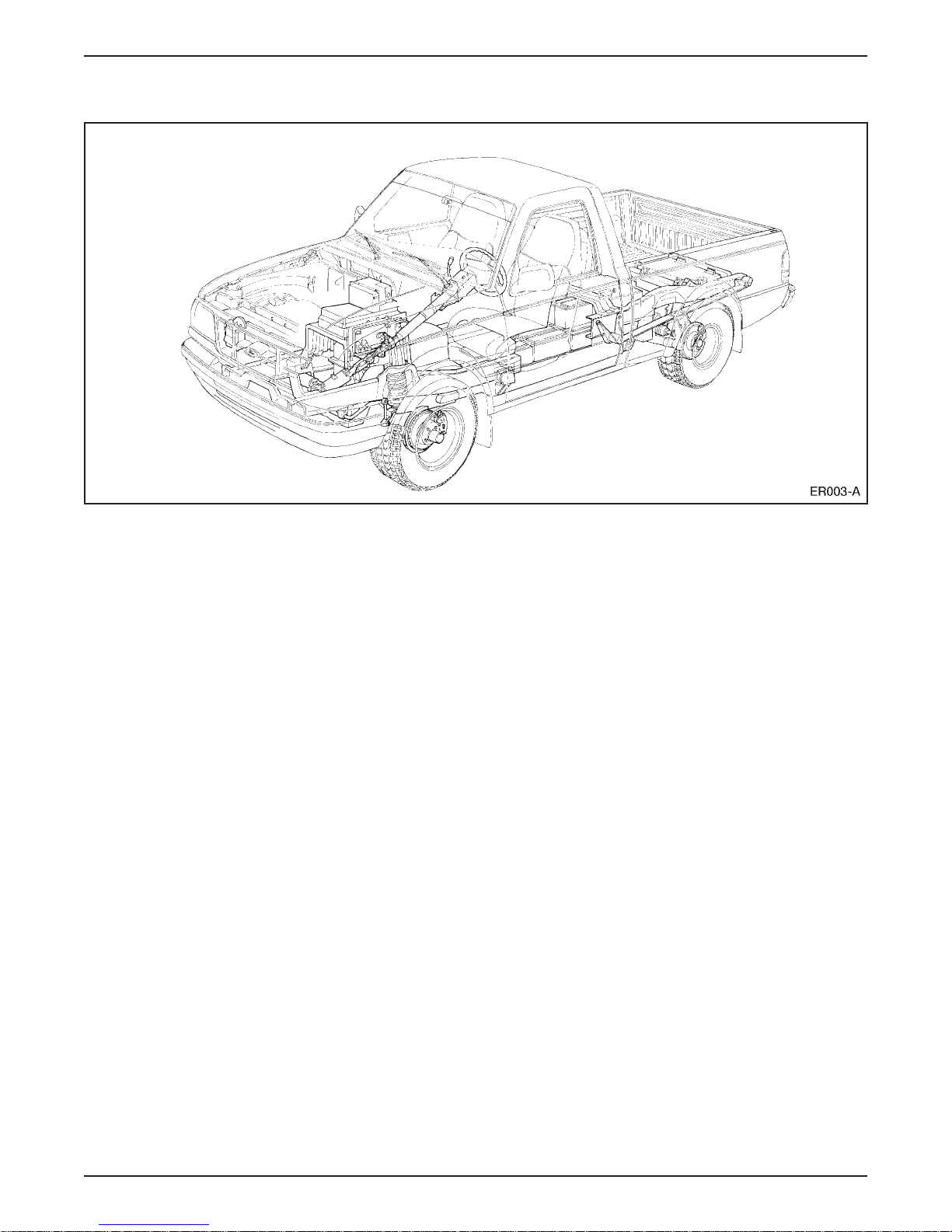
The 1998 Electric Ranger is a low-volume production electric vehicle.
The Electric Ranger is built on the 1998 gasoline-powered Ranger
platform and is sold and serviced through Ford dealerships.
A traction battery mounted under the vehicle between the frame rails
supplies the electric power. The traction battery provides 312 volts
direct current (DC), which is converted to three-phase alternating
current (AC) that drives the motor/transaxle.
The Electric Ranger is a rear-wheel drive vehicle and operates much
like the gasoline-powered models.
The most noticeable difference between the Electric Ranger and the
gasoline-powered Ranger is the operating noise is very low. Because
of the quiet operation of the vehicle, a motor enabled gauge is
provided and is located on the right side of the instrument cluster. The
motor enabled gauge indicates ON with the ignition switch in the
RUN or START position and indicates OFF with the ignition switch
in the OFF position or the powertrain becomes disabled.
1998 Ranger EV New Model Training 1-3
Page 12

LESSON 1: VEHICLE OVERVIEW
SPECIFICATIONS
Vehicle
Model Year 1998
Body Style Styleside, Regular Cab Pick-Up
Wheelbase Short Wheelbase of 2,831 mm (111.4 inch)
Payload 315 kg (700 lb)
Dimensions Similar to 1998 Gasoline-Powered Ranger
Performance
0-50 Mph 12.5 seconds
Top Speed 120 km/h (75 mph)
Range 93 kilometers (58 miles)
Powertrain
Motor High-Efficiency, 3-Phase AC Induction
Horsepower 67 kw (90 hp)
Transaxle Single-Speed Constant-Ratio
Drive Wheels Rear
Gear Ratio 12.518:1
(without A/C or Heater Operation)
Equipment
Standard Dual Air Bags
Electro-Hydraulic Power Steering
Regenerative Braking
4-Wheel ABS
Aluminum Wheels
Low Rolling Resistance Tires
Optional Air Conditioning
Battery Heater
Spare Tire and Jack
1-4 1998 Ranger EV New Model Training
Page 13
LESSON 1: VEHICLE OVERVIEW
BATTERY SYSTEM
Battery System Warnings
WARNING: THE TRACTION BATTERY CAN DELIVER
312 VOLTS OF DC POWER. IMPROPER HANDLING
OF THE TRACTION BATTERY CAN RESULT IN
INJURY OR FATALITY. ONLY AUTHORIZED
PERSONNEL TRAINED TO WORK WITH TRACTION
BATTERY COMPONENTS ARE PERMITTED TO
HANDLE THE BATTERIES.
WARNING: BATTERIES NORMALLY PRODUCE
EXPLOSIVE GASES WHICH CAN CAUSE PERSONAL
INJURY OR DEATH. DO NOT ALLOW FLAMES,
SPARKS OR LIGHTED SUBSTANCES TO COME NEAR
THE BATTERIES. WHEN CHARGING OR WORKING
NEAR THE BATTERIES, ALWAYS SHIELD YOUR
FACE AND PROTECT YOUR EYES. ALWAYS
PROVIDE VENTILATION.
WARNING: LEAD-ACID BATTERIES CONTAIN
SULFURIC ACID. AVOID CONTACT WITH SKIN,
EYES OR CLOTHING. ALSO, SHIELD YOUR EYES
WHEN WORKING NEAR BATTERIES TO PROTECT
AGAINST POSSIBLE SPLASHING OF THE ACID
SOLUTION. IN CASE OF ACID CONTACT WITH THE
SKIN OR EYES, FLUSH IMMEDIATELY WITH
WATER FOR A MINIMUM OF FIFTEEN MINUTES
AND GET PROMPT MEDICAL ATTENTION. IF ACID
IS SWALLOWED, DRINK LARGE QUANTITIES OF
MILK OR WATER, FOLLOWED BY MILK OF
MAGNESIA, A BEATEN EGG, OR VEGETABLE OIL.
CALL A PHYSICIAN IMMEDIATELY.
1998 Ranger EV New Model Training 1-5
Page 14
LESSON 1: VEHICLE OVERVIEW
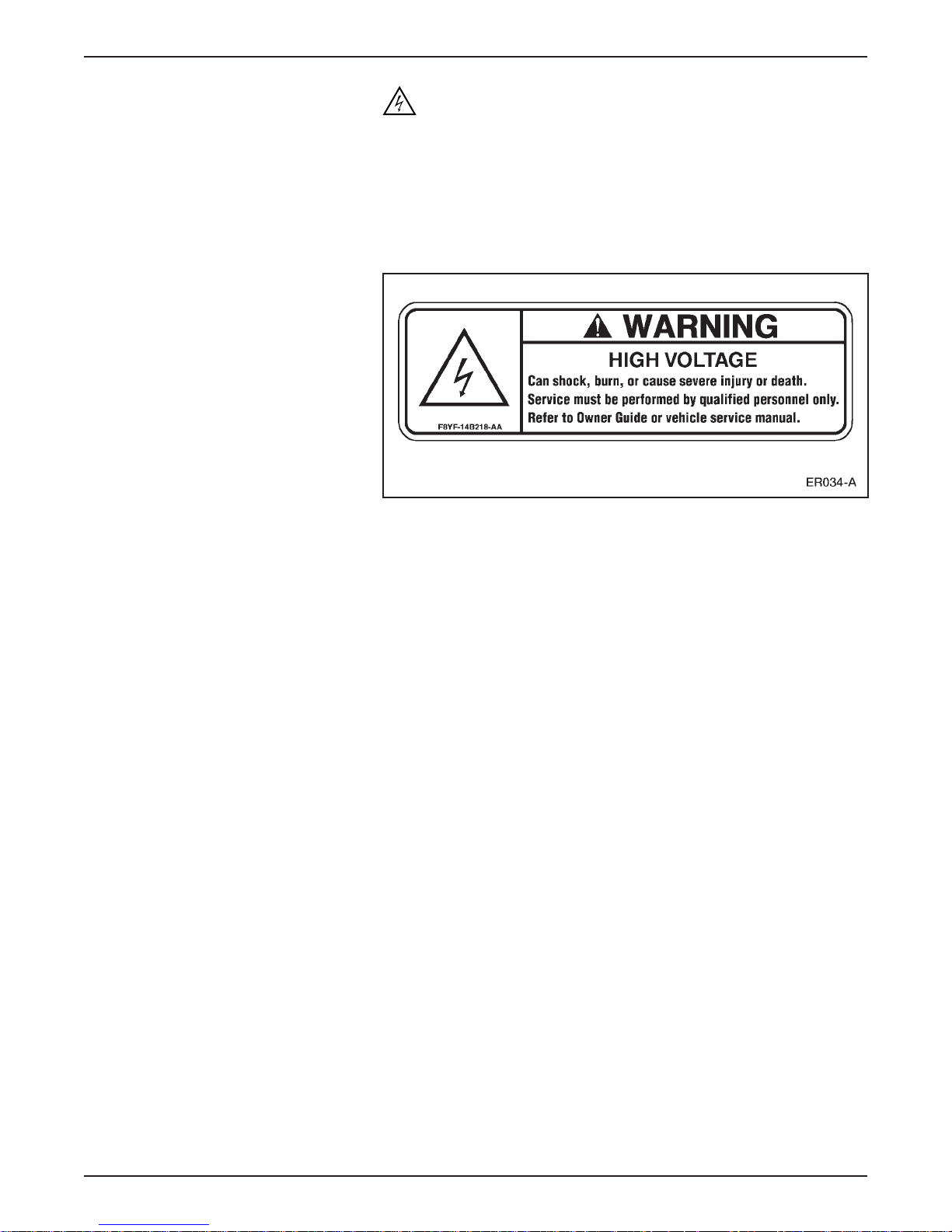
WARNING: HIGH VOLTAGE COMPONENT SERVICE
SHOULD ONLY BE PERFORMED BY TRAINED
PERSONNEL. INCORRECTLY PERFORMING
SERVICE PROCEDURES MAY RESULT IN INJURY OR
DEATH. ALL HIGH VOLTAGE COMPONENTS ON
THIS VEHICLE ARE MARKED WITH THE
FOLLOWING WARNING LABEL.
High Voltage Warning Label
1-6 1998 Ranger EV New Model Training
Page 15
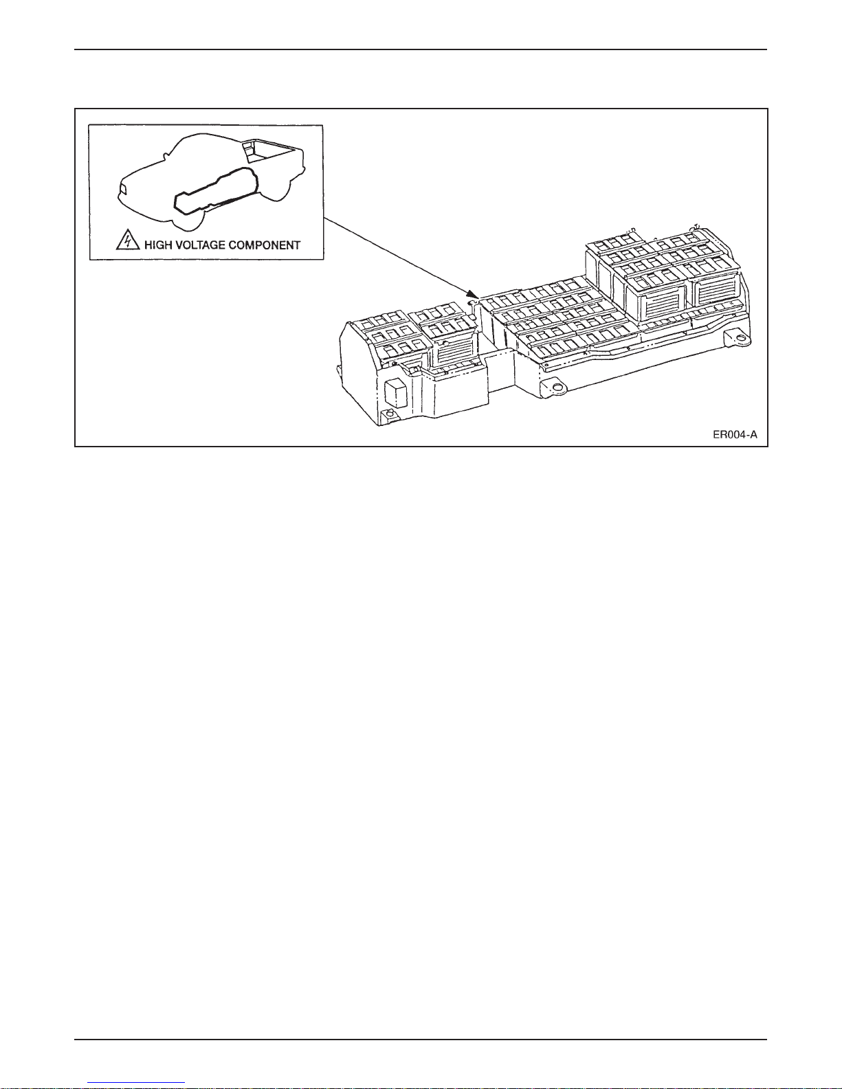
Traction Battery
LESSON 1: VEHICLE OVERVIEW
Traction Battery
• The traction battery is located underneath the vehicle between the
frame rails.
• The traction battery consists of 39 8-volt lead-acid battery modules
stored in a supporting tray.
• The supporting tray is constructed of an extremely strong non-
conductive composite material with bonded metal mounting
brackets.
– The tray is about 8 feet long and weighs almost 900 kg (2000 lb)
with battery modules and associated components in place.
– The supporting tray has a cover which is bolted on. There are
individual battery modules and other components contained
within the traction battery supporting tray.
• The 39 battery modules are arranged in 2 levels, 12 on the upper
level and 27 on the lower level.
• The battery modules are wired in series and produce 312 volts DC.
• A battery control module is located in the upper level at the front of
the assembly.
– The battery control module is secured with Velcro
®
.
1998 Ranger EV New Model Training 1-7
• A contactor box is located in the upper level at the rear of the assembly.
– The contractor box is secured with Velcro
®
.
• A cooling system and a (optional) heating system (for cold climate
areas) are used to maintain optimal temperature within the traction
battery.
Page 16
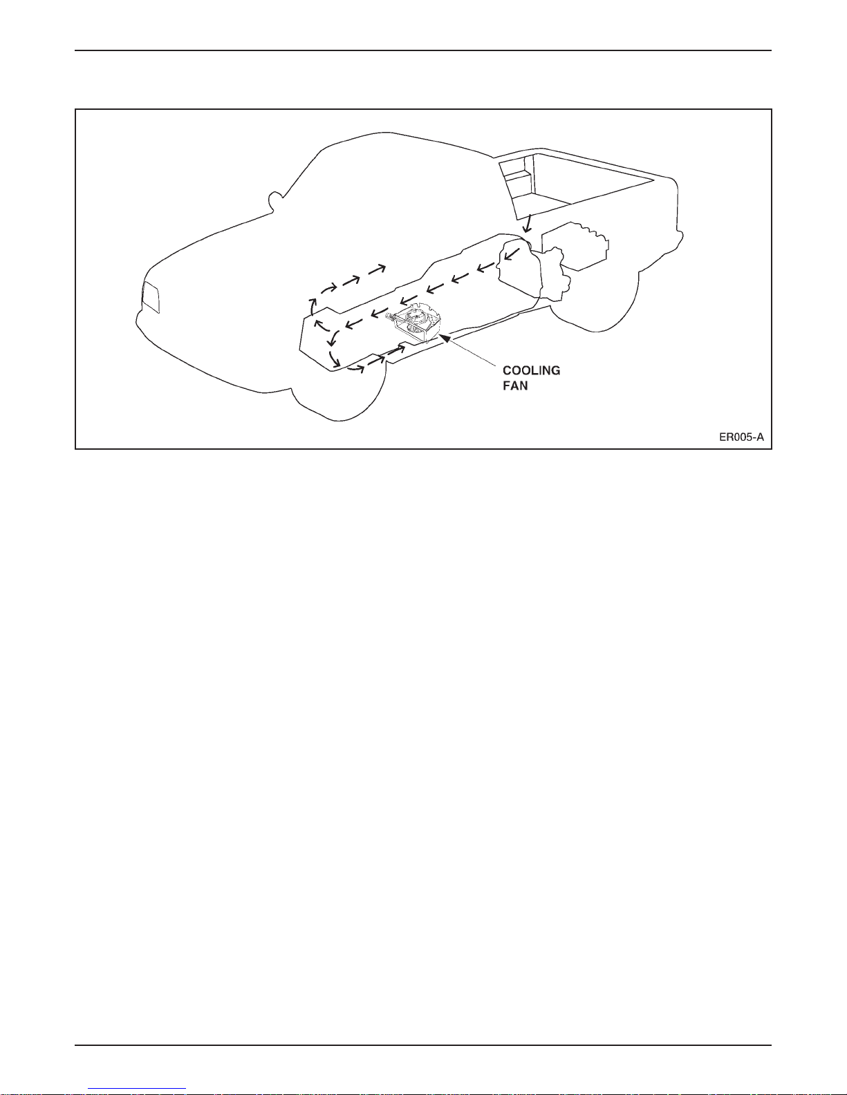
LESSON 1: VEHICLE OVERVIEW
Traction Battery Cooling System
Traction Battery Cooling System
• The traction battery cooling system consists of:
– four temperature sensors.
– a two-speed fan.
– a battery control module.
• The cooling fan is located in the center of the traction battery.
• The cooling function is controlled by the battery control module
(BCM).
• During charging, the cooling fan is used for ventilation and
cooling of the traction battery:
– For ventilation, the cooling fan operates at low speed all the
time.
– For cooling, the cooling fan operates at high speed based on the
temperature of the traction battery.
– For ventilation purposes, the cooling fan operates for 10 minutes
following the completion of the charge cycle.
• During driving, the cooling fan is used for cooling the traction
battery:
– For cooling, the cooling fan operates at high speed based on the
temperature of the traction battery.
– Air is drawn in from the rear of the traction battery and exits
through the front.
1-8 1998 Ranger EV New Model Training
NOTE: Be sure vent openings are clear of obstructions before
connecting charger.
Page 17
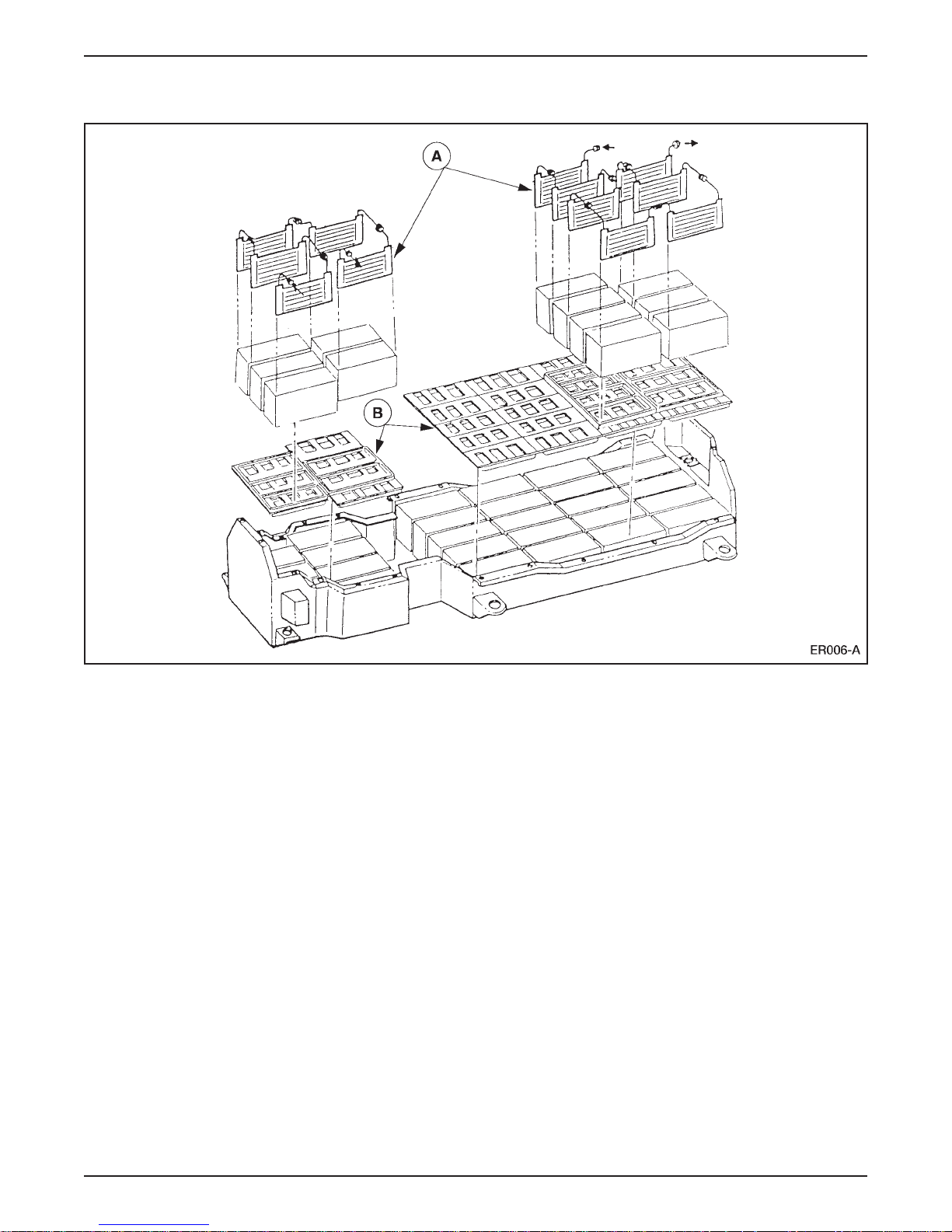
Traction Battery Heating System (Optional)
LESSON 1: VEHICLE OVERVIEW
Optional Traction Battery Heating System
• To maintain proper temperature during charging in cold climates,
• The lower level of battery modules is heated using a blanket
• The upper level uses individual heating elements (A) wired in series.
• The battery heating function is controlled by the battery control
an optional traction battery-heating system is available.
heater (B) to heat the entire lower level.
– The lower level blanket heater is located underneath the battery
modules.
– The upper level heating elements are mounted directly to the
side of each battery module.
module.
– The module will activate the battery heating system if the
traction battery temperature falls below 15°C (59°F) while
connected to an activated charge station.
– Heating function is deactivated when the traction battery
temperature rises above 25°C (77°F). The upper and lower
heating elements may function independently based on input
from temperature sensors.
1998 Ranger EV New Model Training 1-9
Page 18
LESSON 1: VEHICLE OVERVIEW
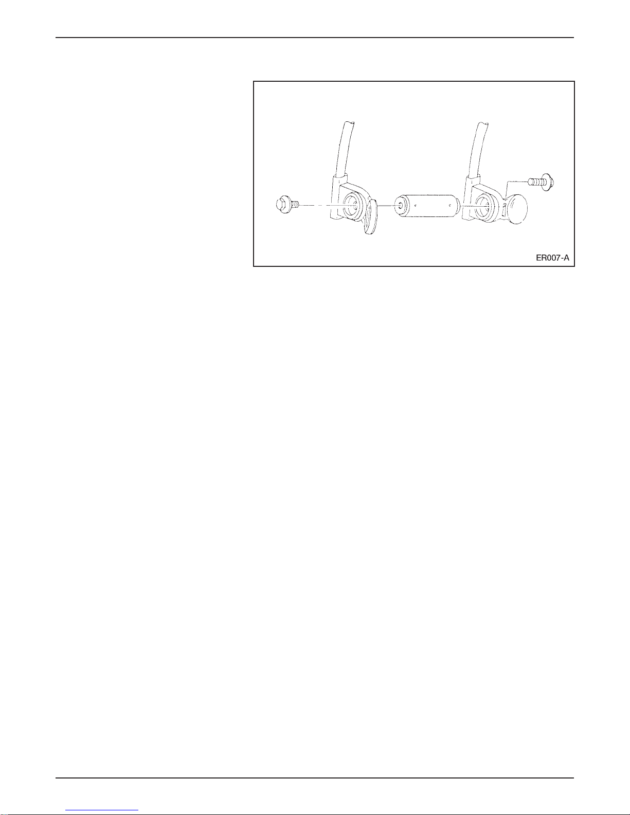
Traction Battery Wiring and Circuit Protection
Traction Battery Circuit Protection
• The traction battery uses low and high voltage wiring.
• The high voltage circuit is protected by a 400-volt 250 amp fuse
installed between batteries 20 and 21.
• If the fuse opens or is removed, the high voltage circuit is
interrupted.
• Two high voltage connectors connect the traction battery to the
vehicle systems.
• The primary power (2-pin) connector is located at the rear of the
battery tray and transfers power to the motor/transaxle.
• The auxiliary power (4-pin) connector is located near the front of
the battery tray on the passenger side. It transfers high voltage
power to the vehicle’s auxiliary high voltage circuits.
• Both high voltage circuits are part of the vehicle high voltage
interlock circuit (covered later in this lesson).
• The low voltage connector is located near the front of the battery
tray on the driver side and transfers low voltage to the vehicle’s
low voltage circuits.
– The low voltage connector is a 76-pin connector.
1-10 1998 Ranger EV New Model Training
Page 19
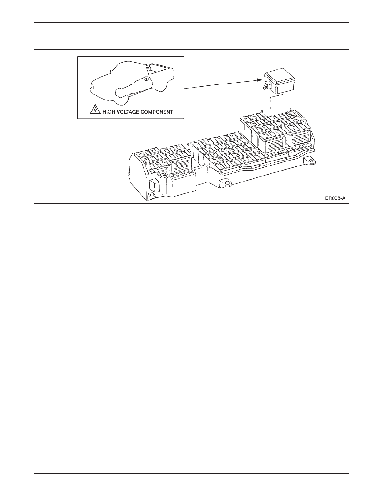
Contactor Box Assembly (CBA)
LESSON 1: VEHICLE OVERVIEW
Contactor Box
• The contactor box assembly (CBA) (arrow) is located in the rear of
the traction battery at the upper left side.
• The contactor box serves as the on/off switches for the traction
battery.
• Relays are used to interrupt the flow of high voltage when the
driver’s key is turned to the OFF position, the inertia shutoff switch
is activated or the system is in shutdown mode actuated by an
electronic control module.
• The contactor box supports these additional functions:
– high voltage circuit precharging – the high voltage circuits
require precharging. Otherwise, the large voltage differential
might weld contactors as circuits are switched on. Precharging is
accomplished through two relays and two 20-ohm resistors
located in the contactor box.
– traction battery current sensing – the contactor box contains two
Hall effect sensors that monitor the current from the traction
battery. One sensor monitors the current flow into the traction
inverter module (TIM) (power for the motor/transaxle),
and the other monitors current flow into the high voltage
auxiliary circuits.
1998 Ranger EV New Model Training 1-11
– high voltage circuit protection – the charging, battery heater and
high voltage auxiliary circuits are protected by three fuses in the
contactor box.
Page 20
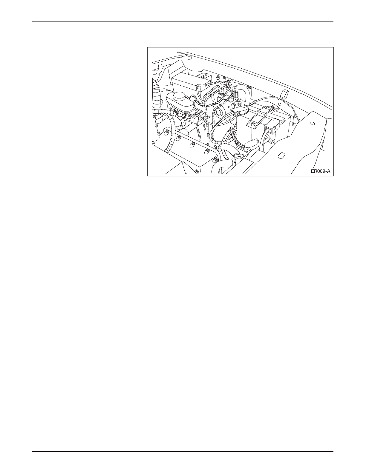
LESSON 1: VEHICLE OVERVIEW
12-Volt Battery
12-Volt Battery Location
• The 12-volt battery is located in the left front corner of the
underhood compartment.
• The 12-volt battery is used for lighting and other low-voltage
circuits and systems.
• The DC/DC converter acts as an alternator to charge the
12-volt battery.
• The 12-volt battery in the Electric Ranger is different than that used
in the gasoline-powered Ranger.
– The Electric Ranger does not require large 12-volt battery
capacity due to the absence of a high current starter circuit.
– The Electric Ranger battery is a 31 amp-hour deep cycle battery.
NOTE: Never attempt to jump-start the 12-volt battery.
1-12 1998 Ranger EV New Model Training
Page 21
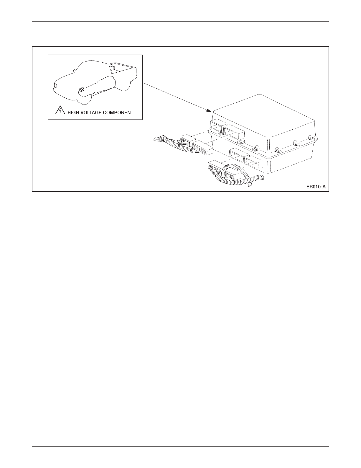
Battery Control Module (BCM)
LESSON 1: VEHICLE OVERVIEW
Battery Control Module (BCM)
• The battery control module (BCM) (arrow) is located in the upper
front section of the traction battery.
• The BCM is a high and low voltage module that controls all battery
system operations.
• The BCM monitors the temperature and state of charge of the
39 battery modules in the traction battery.
• The BCM controls battery charging and cooling.
• The BCM controls the optional battery heating system operation
if equipped.
1998 Ranger EV New Model Training 1-13
Page 22
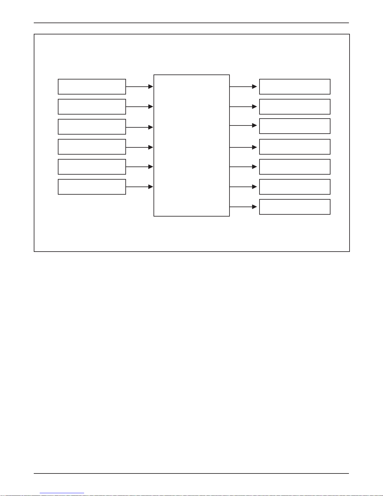
LESSON 1: VEHICLE OVERVIEW
INPUTS
Battery Temperature
Sensor 1-4
Emergency Power Off
(EPO)
Battery V oltage
Sensors
Battery Pack State
Of Charge (SOC)
Digital T ransmission
Range (DTR) Sensor
Charge Cord Plugged
In Signal
BATTERY
CONTROL
MODULE
(BCM)
OUTPUTS
High V oltage Power
Distribution Box (HVDB)
Emergency Power Off
(EPO)
Battery Heaters
Battery Charger
Battery Pack Cooling
Fan
Charger Contactor
Relay
Negative Contactor
Relay
1-14 1998 Ranger EV New Model Training
Page 23
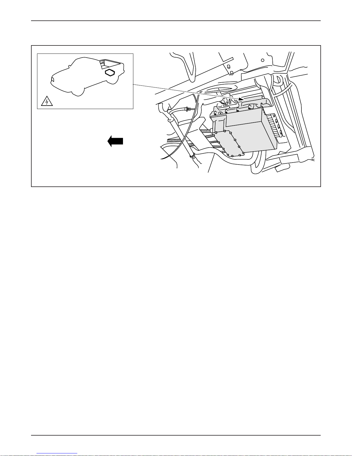
TRACTION INVERTER MODULE (TIM)
HIGH VOLTAGE COMPONENT
LESSON 1: VEHICLE OVERVIEW
ER011-A
Traction Inverter Module (TIM)
• The traction inverter module (TIM) (arrow) is located underneath
the center rear of the vehicle.
• The TIM is a high and low voltage module that performs two
functions:
– vehicle powertrain control
– electric current conversion for the motor/transaxle
• The TIM controls the vehicle powertrain by processing driver,
module, and sensor inputs, and calculating a motor torque
command.
• The TIM converts high voltage DC from the traction battery into
three phase AC used by the motor/transaxle.
• The TIM consists of:
– three high power, high-speed insulated gate bipolar transistor
modules (IGBTs).
1998 Ranger EV New Model Training 1-15
– four large filter capacitors (used during precharging functions).
– two-phase current sensors.
– a high-performance microcontroller.
– logic circuitry and control circuits.
Page 24
LESSON 1: VEHICLE OVERVIEW
• The IGBTs are used to switch on and off the three motor phases.
– As they switch on and off, the IGBTs produce voltage spikes
– Capacitors are used as a filters to protect the TIM and maintain
– These capacitors retain traction battery voltage and provide
NOTE: The TIM is equipped with a bleed down system which
ensures that the capacitors are discharged to less than 50 volts within
two minutes after the driver’s key is turned to the OFF position.
• Be sure to allow for capacitor bleed down time before attempting
maintenance or repair.
that have the potential to damage the TIM.
traction bus voltage during IGBT switching.
current capability for instantaneous torque.
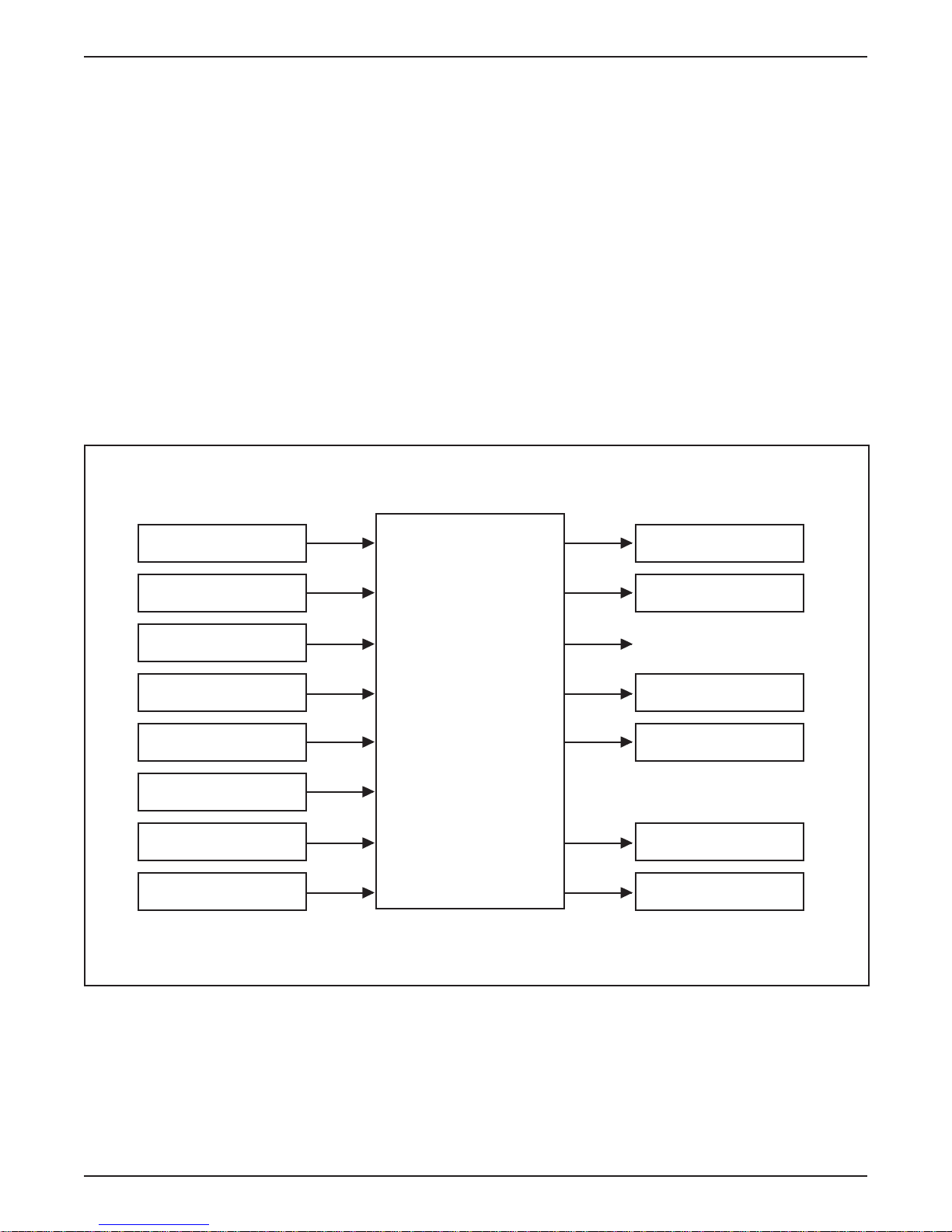
INPUTS
Motor Temperature
Sensor
Emergency Power Off
(EPO)
Accelerator Pedal
Sensors 1-3
Anti-Lock Brake
Module
Brake Pedal Sensor
Digital T ransmission
Range (DTR) Sensor
Charge Cord Plugged
In Signal
Oil Pressure Sensor
TRACTION
INVERTER
MODULE
(TIM)
OUTPUTS
Vehicle Speed Signal
Emergency Power Off
(EPO)
Electric Motor/
Transaxle
Precharge Contactor
Relay
Main Contactor Relay
Oil Pump Relay
1-16 1998 Ranger EV New Model Training
Page 25
LESSON 1: VEHICLE OVERVIEW
INTERFACE ADAPTER ASSEMBLY (IAA)
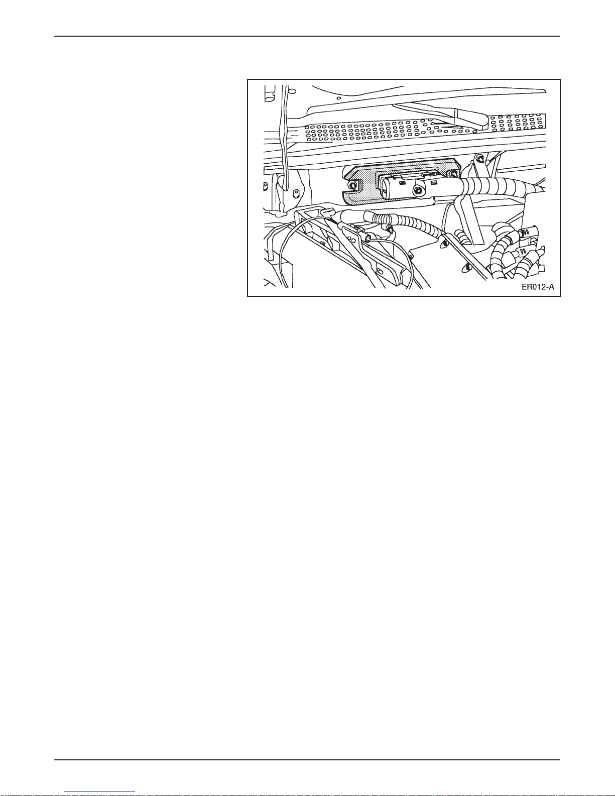
Interface Adapter Assembly (IAA)
• The interface adapter assembly (IAA) is located on the bulkhead
under the instrument panel, the same location as the gasolinepowered Ranger EEC-V module.
• The IAA is a low voltage multi-function module that manages the
climate control system, the auxiliary systems and most instrument
cluster gauges and lamps.
• The IAA is networked with the TIM and the BCM to support
instrument cluster functions, contactor box operations, and
diagnostics.
• The IAA diagnostics are accessible through the OBD-II diagnostic
connector under the instrument panel next to the steering column.
• Diagnostic functions as well as parameter identification (PID) data
and active command modes are available.
• Based on operator and vehicle demands, the IAA controls these
functions:
– High voltage A/C compressor (optional).
– High voltage positive temperature coefficient (PTC) heater.
1998 Ranger EV New Model Training 1-17
– Air distribution blend door and climate control blower fan
motor.
– Power steering.
– DC/DC converter.
– Vacuum pump.
– Liquid cooling system coolant pump and two-speed radiator fan.
– Instrument cluster operation.
Page 26
LESSON 1: VEHICLE OVERVIEW
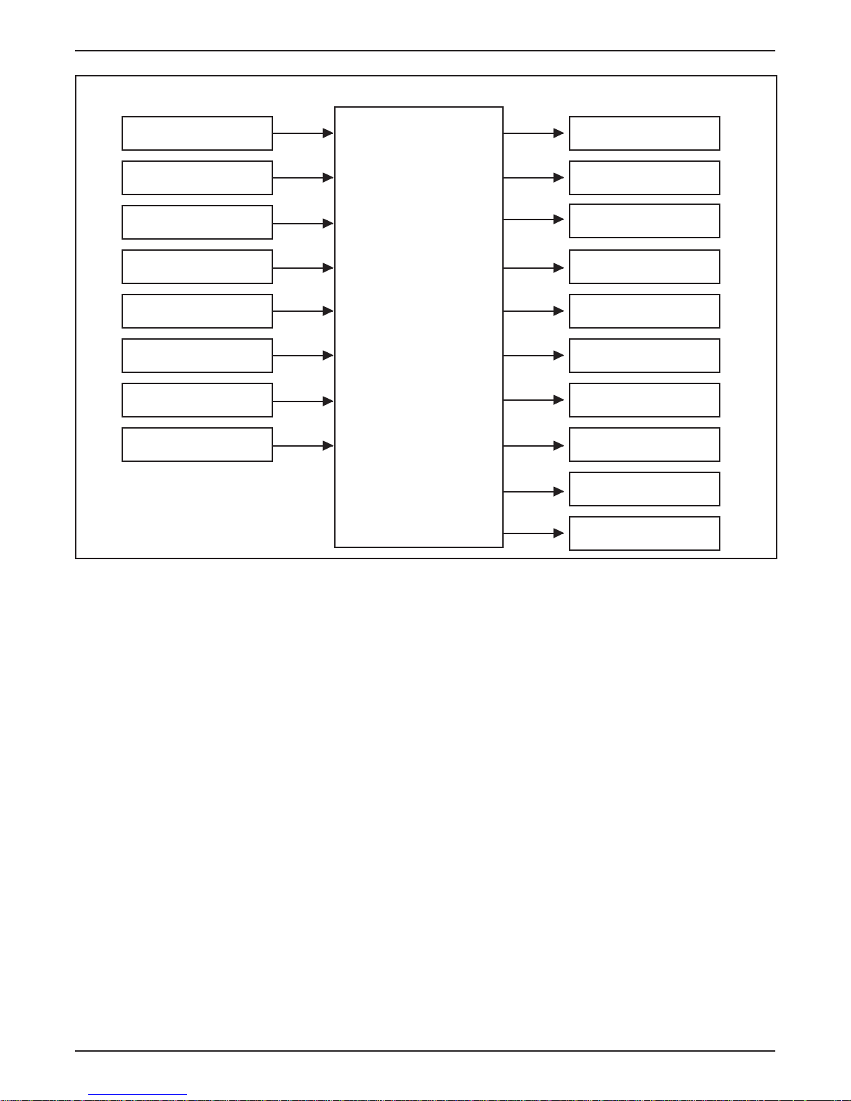
INPUTS
Blower Motor Speed
Emergency Power Off
(EPO)
A/C Pressure Sensor
Vacuum Pressure
Sensor
Coolant Temperature
Sensor
Brake Fluid Level
Switch
PTC Heater Switching
Module
Steering Wheel
Sensors
INTERF ACE
ADAPTER
ASSEMBLY
(IAA)
OUTPUTS
PTC Heater Cores
Emergency Power Off
(EPO)
Vacuum Pump
A/C Compressor
DC/DC Converter
Cooling Fan Relay
Auxiliary Contactor
Relay
Power Steering
Control
Instrument Gauges
and Lights
Air Distribution
Blend Doors
1-18 1998 Ranger EV New Model Training
Page 27
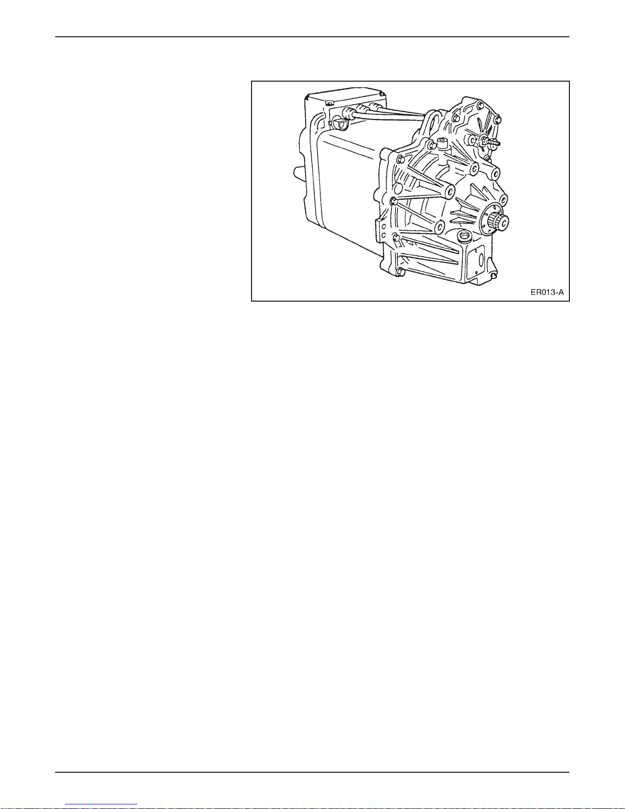
LESSON 1: VEHICLE OVERVIEW
MOTOR/TRANSAXLE
Motor/Transaxle Assembly
• The motor/transaxle is mounted just behind the traction battery.
• The motor/transaxle assembly consists of a:
– four-pole, three phase AC induction motor.
– single-speed transaxle with a planetary gearset.
• The motor/transaxle supplies power through halfshafts to the
rear wheels.
– A peak power of 67 kW (90 hp) is produced at 190 Nm
(140 lb ft) torque.
• The assembly is packaged in an aluminum case and weighs
approximately 91 kg (200 lb).
1998 Ranger EV New Model Training 1-19
Page 28
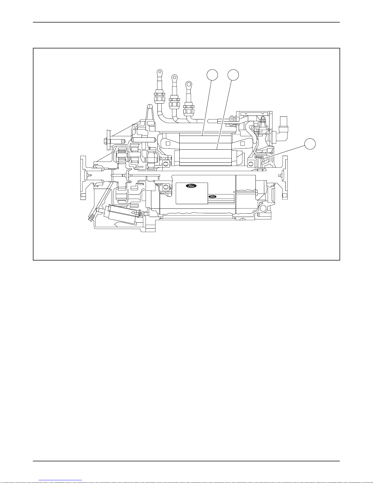
LESSON 1: VEHICLE OVERVIEW
Motor
A B
C
Motor Components
ER014-A
• The AC induction motor consists of a:
– stator (A).
– cast aluminum rotor (B).
– rotor speed sensor (C).
• The motor has a maximum operating speed of 13,000 rpm and
maximum current draw of 305 amps.
1-20 1998 Ranger EV New Model Training
Page 29

LESSON 1: VEHICLE OVERVIEW
• Alternating current is supplied from the TIM to the motor through
high voltage cables.
– Current flows through the stator windings generating a
magnetic field.
– The magnetic field causes the rotor to spin.
– Varying the amount of current controls torque.
– Varying the AC current frequency controls speed.
– During deceleration and braking, a negative torque is produced,
and the motor acts as a generator and regenerates charge in the
traction battery.
1998 Ranger EV New Model Training 1-21
Page 30
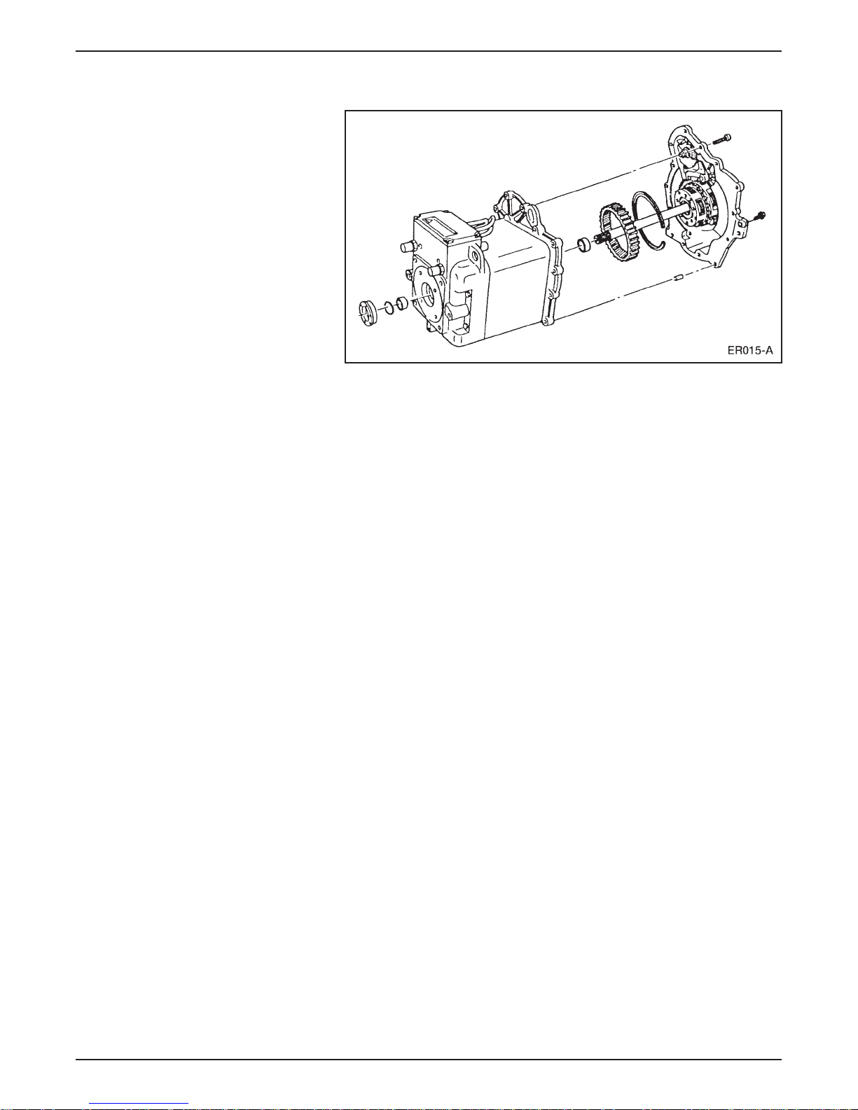
LESSON 1: VEHICLE OVERVIEW
Transaxle
Transaxle Components
• The transaxle consists of a:
– two-stage direct reduction planetary gear system (similar to
other automatic transaxle planetary gear sets).
– 50/50 planetary differential.
• The transaxle is a constant-ratio (one-speed) unit and uses no apply
components.
– There are no clutches, bands, or valves as in multiple-speed
transaxle units.
• A cam-operated parking pawl is operated manually by the gear
selector assembly through the shift cable and shift lever.
• The cam has five detent positions:
– Park (P)
– Reverse (R)
– Neutral (N)
– Drive (D)
– Economy (E)
1-22 1998 Ranger EV New Model Training
Page 31

LESSON 1: VEHICLE OVERVIEW
• Direction (clockwise or counterclockwise) and speed of the motor
are monitored by a speed sensor mounted inside the transaxle case.
– The speed sensor detects passing teeth on the speed wheel as it
rotates.
– The speed wheel is mounted to the input shaft.
– The speed (rpm) signal is sent to the TIM.
• The transaxle is lubricated by Tribolube-L6 (Pro Gear 21), a
synthetic, low-viscosity oil.
• A 12-volt DC oil pump mounted inside the case supplies oil to
lubricate the gears and bearings.
– The pump is controlled by the TIM.
– Normal pressure is approximately 103 kPa (15 psi).
– If pressure drops below 28 kPa (4 psi), the oil pressure switch
opens and signals the TIM.
• Motor/transaxle cooling is provided by the vehicle liquid cooling
system (covered later in this lesson).
NOTE: Adding transaxle oil is not a standard maintenance item.
Change transaxle oil at 3 year intervals.
1998 Ranger EV New Model Training 1-23
Page 32
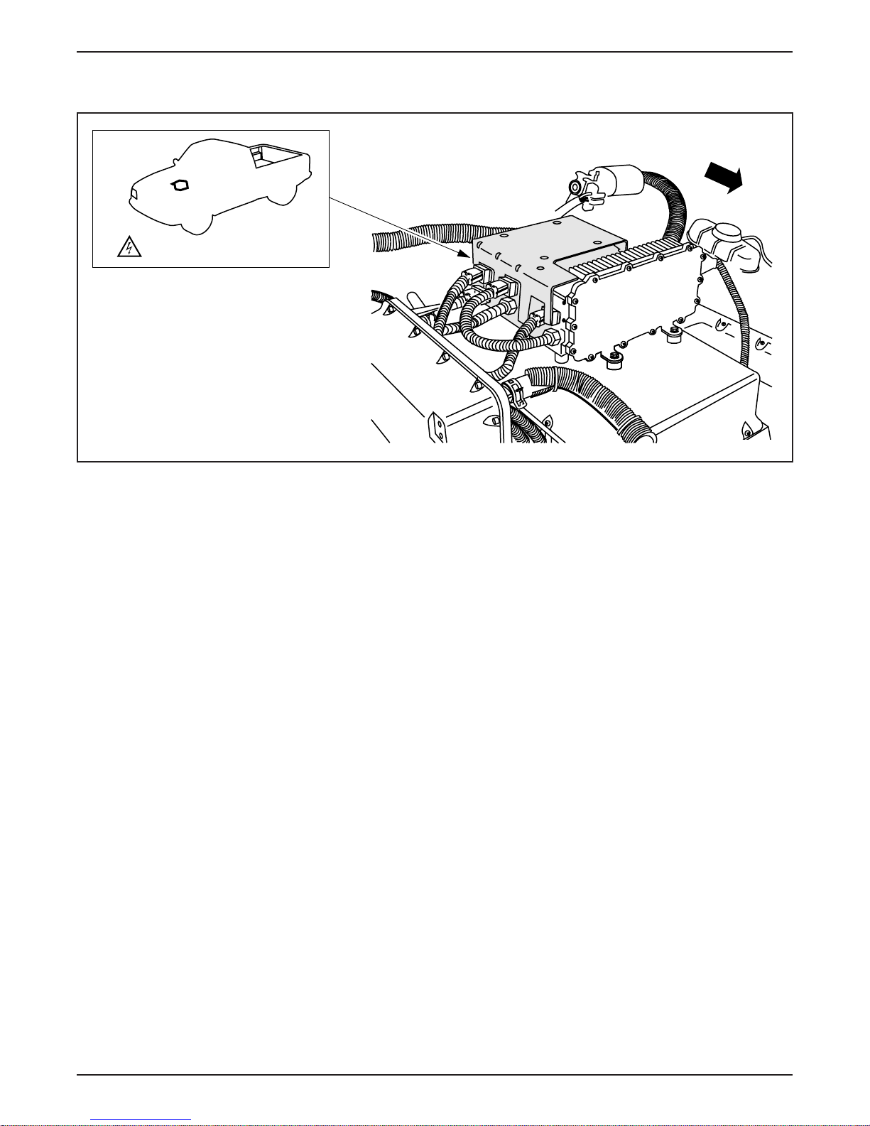
LESSON 1: VEHICLE OVERVIEW
HIGH VOLTAGE POWER DISTRIBUTION BOX
HIGH VOLTAGE COMPONENT
ER016-A
High Voltage Power Distribution Box
• The high voltage power distribution box (arrow) is located in the
underhood compartment on top of the battery charger.
• The high voltage power distribution box is similar in function to
the fuse box in your home.
– It distributes high voltage to components and systems.
– It contains fuses.
• The power distribution box directs fuse protected high voltage to:
– DC/DC converter.
– Heating system.
– Air conditioning system (optional).
– Power steering system.
– Battery charger.
• The power distribution box has a protective cover that is part of the
high voltage interlock circuit (covered later in this lesson).
1-24 1998 Ranger EV New Model Training
– When the cover is removed, a limit switch will open the relays
in the contactor box, which interrupts high voltage to the
vehicle systems.
Page 33
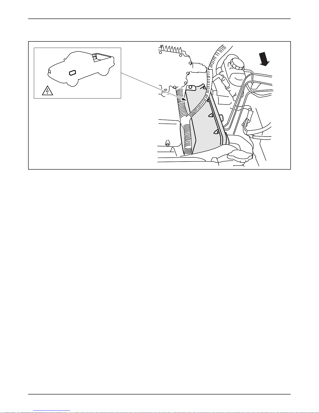
DC/DC CONVERTER
HIGH VOLTAGE COMPONENT
LESSON 1: VEHICLE OVERVIEW
ER017-A
DC/DC Converter
• The DC/DC converter (arrow) is located in the underhood
compartment on the driver side of the battery charger.
• The DC/DC converter acts as an electronic alternator, charging the
12-volt battery and supplying power for low voltage components
and systems.
• The DC/DC converter steps down traction battery voltage from
312 volts to 12 volts.
• A temperature sensor mounted near the 12-volt battery tray allows
the converter to adjust voltage to the 12-volt battery as temperature
changes.
• The DC/DC converter is controlled by the IAA.
• The DC/DC converter operates when the key is in the ON position
and with the key in the OFF position when the vehicle is connected
to the power control station (PCS) for charging.
1998 Ranger EV New Model Training 1-25
Page 34
LESSON 1: VEHICLE OVERVIEW
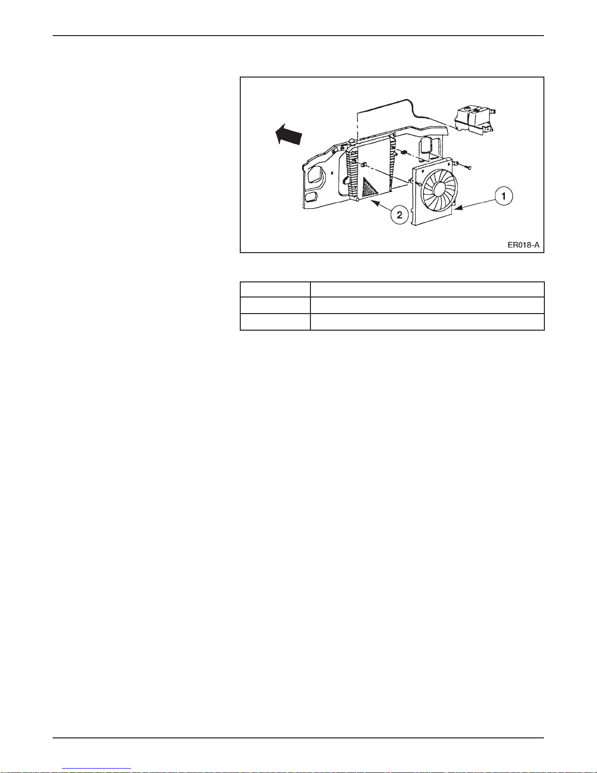
LIQUID COOLING SYSTEM
Liquid Cooling System Components
Item Description
1 Two-Speed Electric Cooling Fan
2 Radiator
• The high voltage electronics used on the Electric Ranger require
cooling under normal use.
• Excess heat is removed by a liquid cooling system controlled by
the IAA.
• The liquid cooling system cools the:
– TIM.
– motor/transaxle.
– DC/DC converter.
– A/C inverter motor controller.
1-26 1998 Ranger EV New Model Training
Page 35

LESSON 1: VEHICLE OVERVIEW
• The liquid cooling system consists of:
– an Explorer radiator.
– a two-speed electric cooling fan.
– a 12-volt electric coolant pump.
– rubber coolant hoses.
– metal coolant tubes.
– a 50/50 mix of water and glycol Ford specification WSS-
M97B44-C. (Do not mix with previous specification.)
• The 12-volt coolant pump incorporates a:
– centrifugal impeller design.
– 12-volt DC motor.
– magnetic motor-to-impeller clutch.
NOTE: Adding coolant is not a standard maintenance item. Do not
mix the new glycol with the previous specification. Change coolant at
100,000 miles or 5 years whichever comes first.
1998 Ranger EV New Model Training 1-27
Page 36
LESSON 1: VEHICLE OVERVIEW
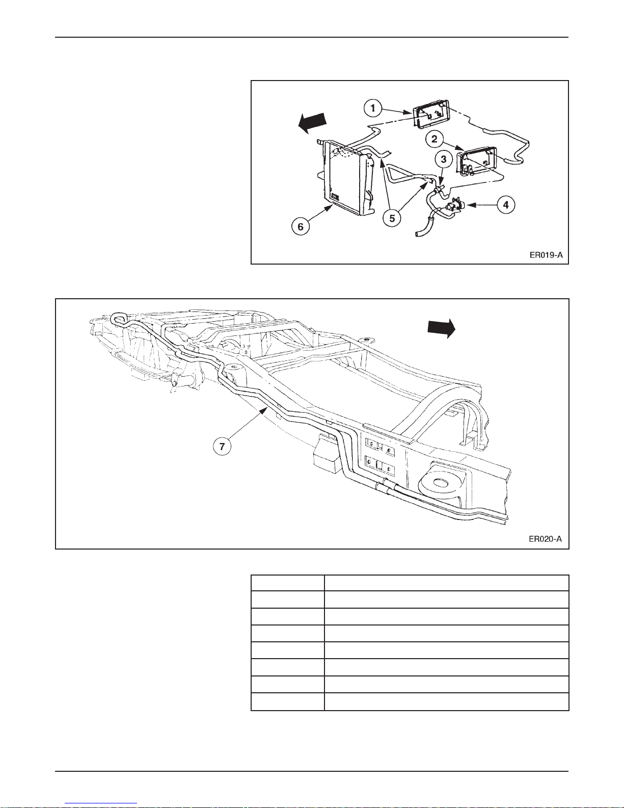
Coolant Hose Routing
Coolant Hose Routing
1-28 1998 Ranger EV New Model Training
Item Description
1 A/C Inverter Motor Controller
2 DC/DC Converter
3 Coolant Temperature Sensor
4 12-Volt Electric Coolant Pump Motor
5 Rubber Coolant Hoses
6 Electric Cooling Fan Module (not shown)
7 Metal Coolant Tubes
Page 37

LESSON 1: VEHICLE OVERVIEW
• Coolant is circulated by the electric pump located below the
DC/DC converter.
• Rubber hoses carry coolant to the DC/DC converter and the
A/C inverter motor controller.
• Rubber hoses and metal tubes carry coolant to the motor/transaxle
and TIM.
• An electric cooling fan module is mounted on the lower right
section of the radiator.
• The coolant temperature sensor is located in the hose connector
above the electric pump.
• The liquid cooling system operates whenever the driver’s key in the
ON position.
– It also operates during battery charging if the DC/DC converter
is charging the 12-volt battery.
1998 Ranger EV New Model Training 1-29
Page 38
LESSON 1: VEHICLE OVERVIEW
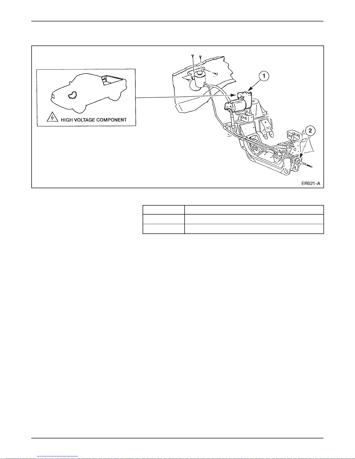
POWER STEERING SYSTEM
Power Steering System Components
Item Description
1 Power Steering Controller Assembly
2 Power Steering Gear and Linkage
• The power steering controller assembly is located on the right side
of the underhood compartment.
• The power steering controller assembly consists of an electric
controller attached to a high voltage AC electric motor and pump.
• The electronic controller has its own inverter to convert DC voltage
from the traction battery into the high voltage AC required by
the motor.
• The assembly has one high voltage connector and one low voltage
connector.
• The steering linkage and power steering gear are carryover from
gasoline-powered Ranger.
• The steering column is a Ranger tilt column to accommodate a
steering wheel rotation sensor that provides input for additional
power assist when the vehicle is at a stop.
1-30 1998 Ranger EV New Model Training
Page 39

NOTES
LESSON 1: VEHICLE OVERVIEW
1998 Ranger EV New Model Training 1-31
Page 40
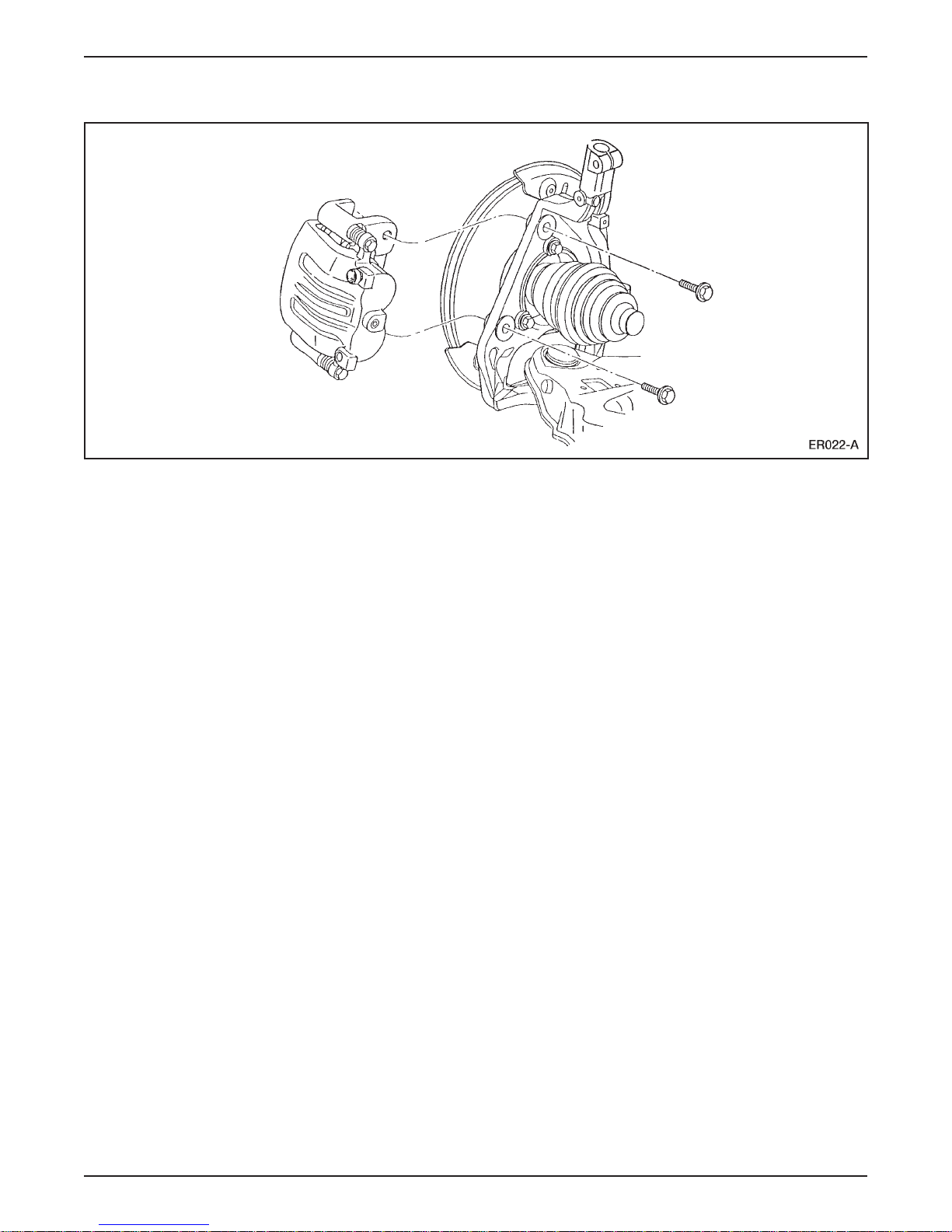
LESSON 1: VEHICLE OVERVIEW
BRAKING SYSTEM
Braking System Components
• The base brake system is a conventional hydraulic/friction braking
system.
• The brake booster and master cylinder are carryover from the
gasoline-powered Ranger.
• The master cylinder includes a modified pressure sensor that
provides input for the regenerative braking system.
• The front and rear discs and calipers (above) are carryover
Explorer.
– The hubs are similar to those used on Thunderbird.
1-32 1998 Ranger EV New Model Training
Page 41
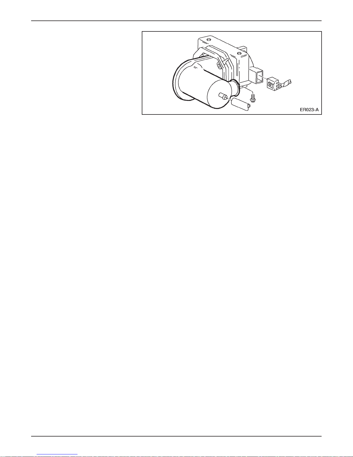
LESSON 1: VEHICLE OVERVIEW
Motor Driven Vacuum Pump
• A motor driven vacuum pump is mounted beneath the
battery charger.
• The anti-lock braking system (ABS) is a 4-sensor 3-channel
system.
• ABS components include:
– an electronic control unit (ECU).
– an Explorer hydraulic control unit (HCU).
– a Ranger mounting bracket.
• The ABS system sends active line output to the TIM for use with
the regenerative braking system.
• All of the electric components in the braking system operate off
low voltage circuits.
1998 Ranger EV New Model Training 1-33
Page 42
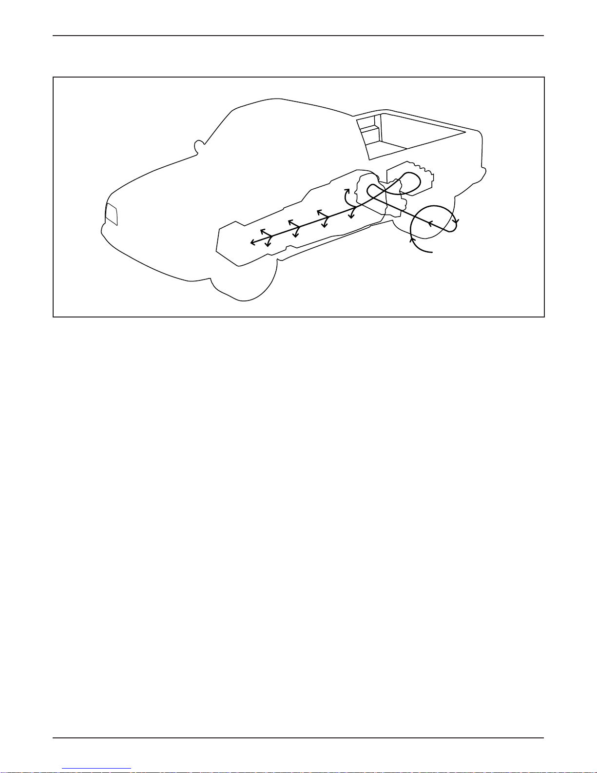
LESSON 1: VEHICLE OVERVIEW
Regenerative Braking System (RBS)
Electrical
energy
Kinetic
energy
ER024-A
Regenerative Braking System (RBS)
• In a conventional friction braking system, the kinetic energy of
deceleration is transformed into heat.
– This heat is dissipated into the surrounding air.
• The function of the regenerative braking system (RBS) is to
recover some of this kinetic energy during deceleration and
improve overall vehicle efficiency.
• Regenerative braking is accomplished by using vehicle
deceleration to drive the motor/transaxle.
– This causes the motor to act as a generator and convert vehicle
kinetic energy into electrical energy that is stored by the traction
battery.
1-34 1998 Ranger EV New Model Training
Page 43

LESSON 1: VEHICLE OVERVIEW
• The accelerator pedal and the brake pedal are inputs of the RBS.
• RBS supplements the hydraulic braking system.
• The RBS operates when the vehicle is moving either forward or
backward.
• It is possible for RBS motor torque to cause rear wheel slip in
certain circumstances.
– To prevent excessive wheel slip, the RBS is designed to work
with the anti-lock brake system (ABS) module.
– Whenever an ABS event occurs, the ABS module signals the
TIM, which reduces regenerative braking.
– The RBS is returned to its prior state after the ABS event.
NOTE: The IAA triggers the red BRAKE warning lamp in the
instrument cluster if an RBS fault occurs. The vehicle can be safely
operated without RBS.
1998 Ranger EV New Model Training 1-35
Page 44
LESSON 1: VEHICLE OVERVIEW
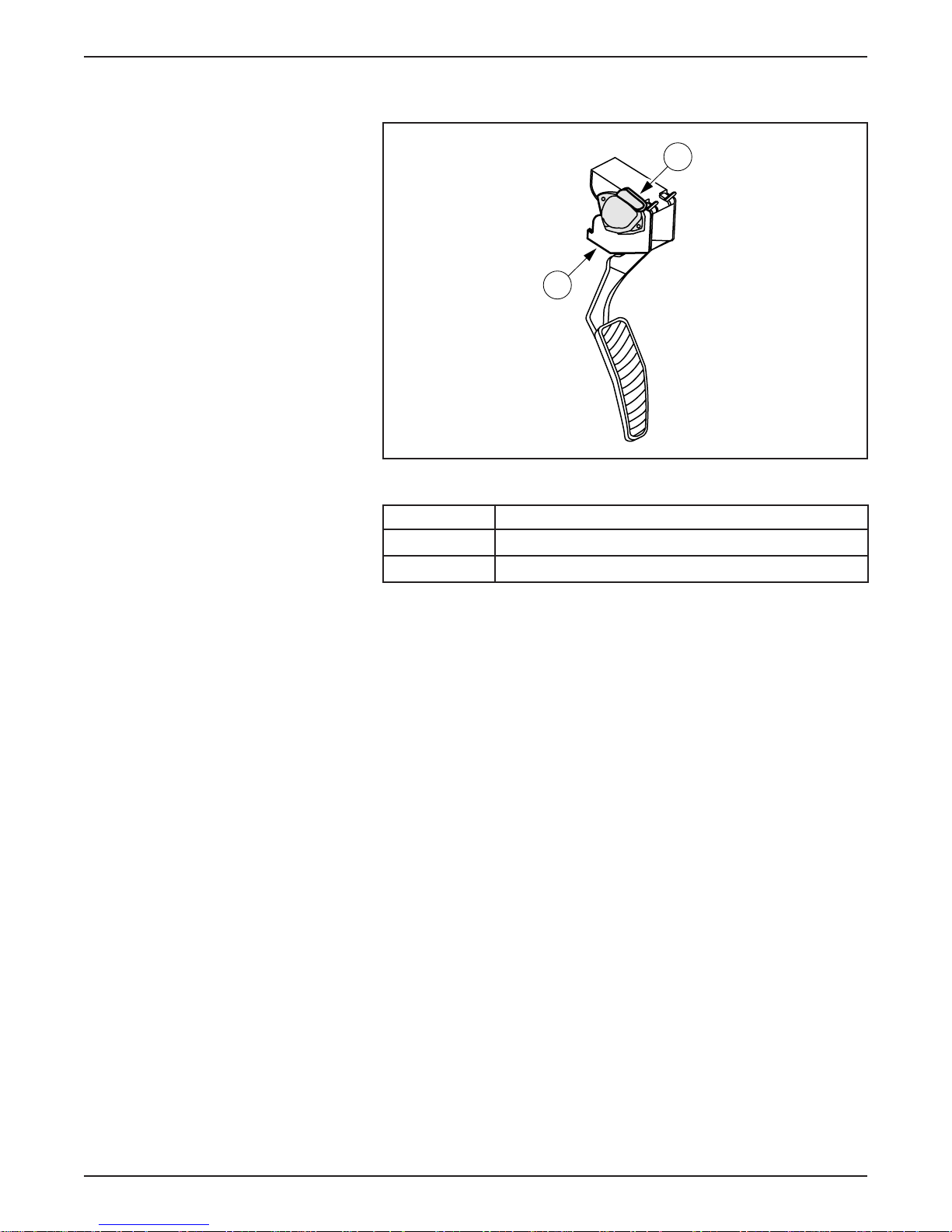
ELECTRONIC THROTTLE CONTROL
Electronic Throttle Control Components
1
2
ER025-A
Item Description
1 Accelerator Position Sensor (APS)
2 Accelerator Pedal Assembly
• Electronic throttle control is in use on vehicles other than
Electric Ranger.
• On the Electric Ranger, electronic throttle control replaces the
cable between the accelerator pedal and the powertrain.
• Instead of a mechanical request for power, electronic throttle
control uses electrical signals.
• The sensing component of electronic throttle control is an
accelerator position sensor (APS) mounted to the accelerator
pedal assembly.
– Three potentiometers in the APS sense the position of the
accelerator pedal.
– The APS sends signals to the TIM, which commands the
motor/transaxle to respond accordingly.
1-36 1998 Ranger EV New Model Training
Page 45
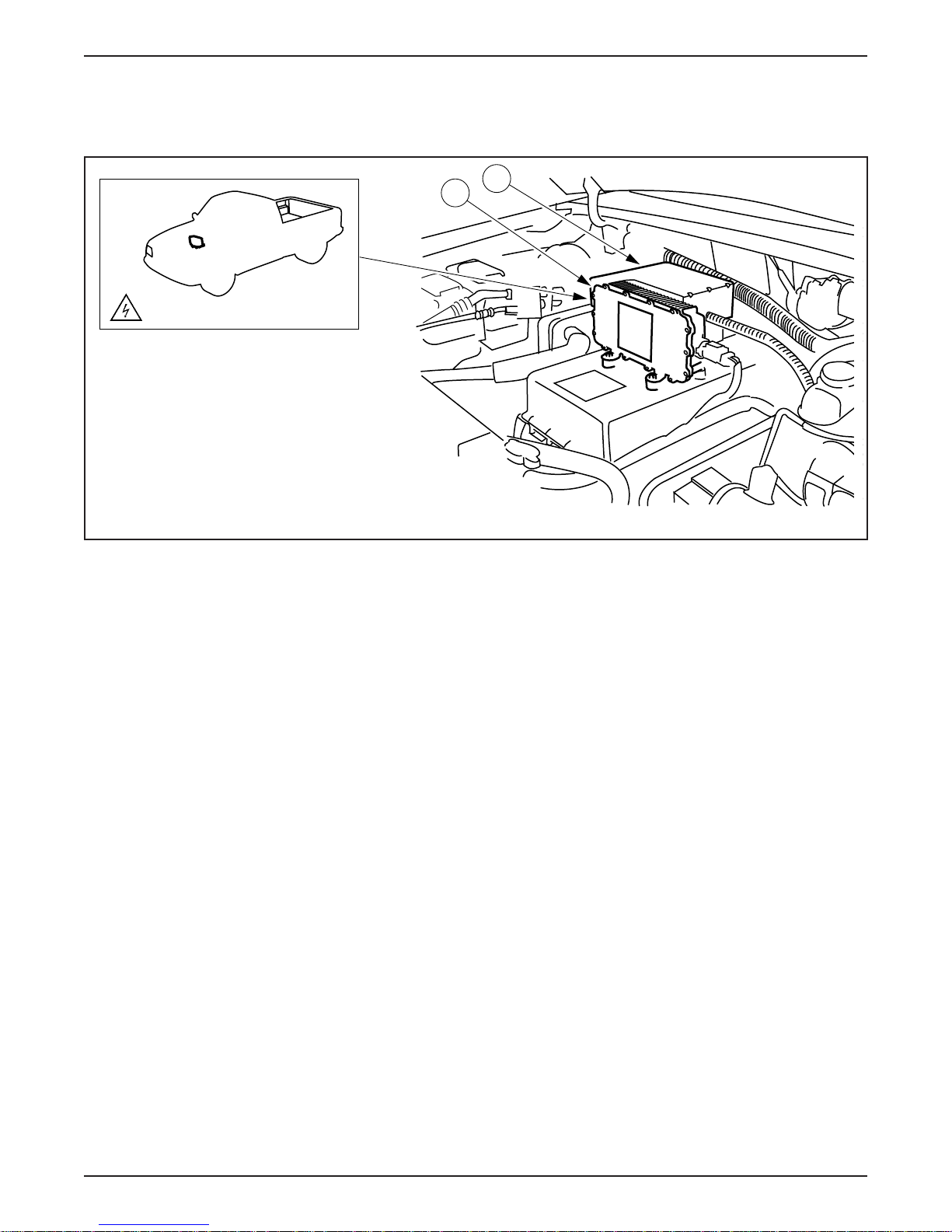
CLIMATE CONTROL SYSTEM
Heating System Description
HIGH VOLTAGE COMPONENT
LESSON 1: VEHICLE OVERVIEW
B
A
Heating System
ER026-A
• In place of using engine coolant to heat the passenger
compartment, the Electric Ranger uses a positive temperature
coefficient (PTC) heater.
• A PTC switching module (A) provides high voltage to the
PTC heater.
• The PTC switching module is located in the underhood
compartment in front of the high voltage power distribution
box (B).
• The module is controlled by the IAA, and provides fault feedback
to the IAA, if any of the following faults occur:
– A short in the PTC switching module
– A heater core over-temperature condition
– A heater core fault
1998 Ranger EV New Model Training 1-37
• Feedback is provided on heater core fault conditions (open, short,
or over current).
Page 46
LESSON 1: VEHICLE OVERVIEW
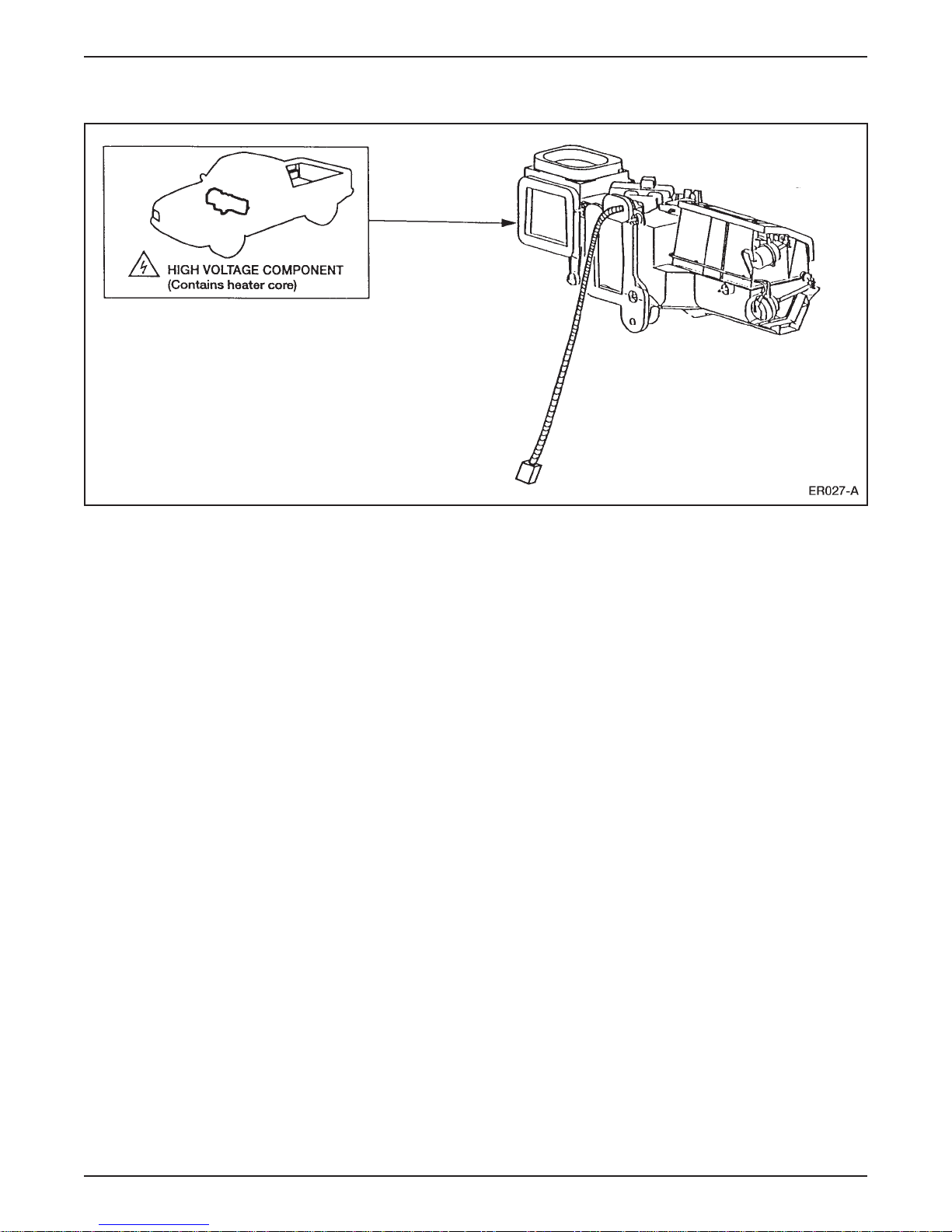
Heating System Operation
Heater Assembly
• The PTC heater is an electric resistance heater with a two-stage
heater core that operates on two separate circuits.
• The heater core uses high voltage DC from the traction battery to
defrost the windshield and heat the passenger compartment.
• The heater core is housed in the heater plenum under the
instrument panel.
– The plenum is modified from the gasoline-powered
Ranger assembly.
– The vacuum system, blend door actuator, fresh/recirculation
solenoid, over-temperature switch, and wiring harness are new,
and the seals are modified.
– The evaporator assembly is a modified gasoline-powered
Ranger assembly.
– The blower motor and serviceable air filter are new (the air filter
is replaced annually). Air filter is located inside the blower
motor housing.
1-38 1998 Ranger EV New Model Training
Page 47

LESSON 1: VEHICLE OVERVIEW
• The manual control head is a modified gasoline-powered Ranger
design with a:
– mode switch.
– blower switch.
– temperature potentiometer.
• A new recirculation switch allows heat to be recirculated.
• The ambient and in-vehicle temperature sensors are carryover from
Explorer.
• Heating temperature in the passenger compartment is limited to
27°C (80°F) to conserve traction battery power.
1998 Ranger EV New Model Training 1-39
Page 48
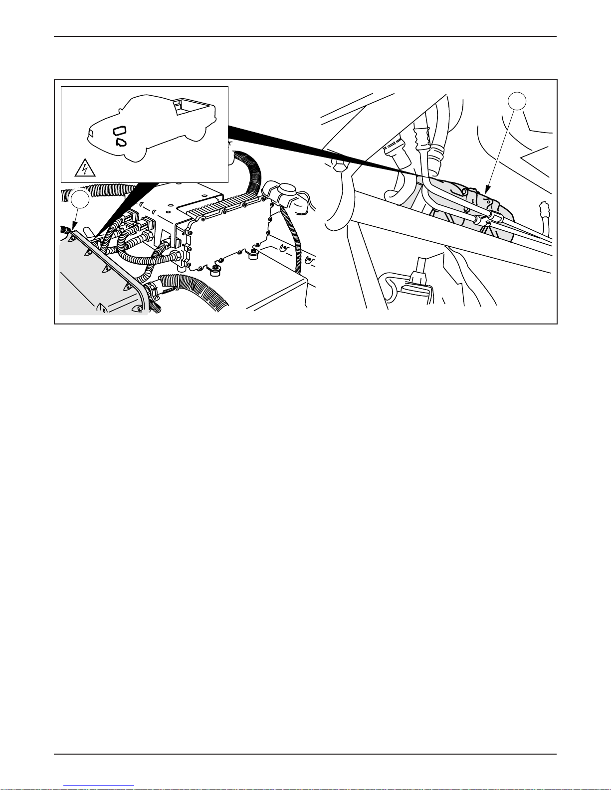
LESSON 1: VEHICLE OVERVIEW
Air Conditioning System
HIGH VOLTAGE COMPONENTS
A
B
ER028-A
Air Conditioning System Components
• The air conditioning compressor (B) is located in the lower center
of the under hood compartment.
• The absence of an internal combustion engine means there is no
drive belt to power a pulley-driven compressor.
• The Electric Ranger uses an AC high voltage variable-speed
compressor.
– The AC high voltage is supplied by the A/C inverter motor
controller (A).
– The A/C inverter motor controller has a case similar to the
design of the DC/DC converter and is located next to the battery
charger.
– The controller contains three IGBTs for high speed current
switching.
1-40 1998 Ranger EV New Model Training
Page 49

LESSON 1: VEHICLE OVERVIEW
• The compressor is located in the lower center of the underhood
compartment and:
– is a 33 cc scroll design.
– has an integral 3.5 kW (4.7 hp) motor.
– has a maximum shaft speed of 7812 rpm.
• The A/C system is a modified Ranger clutch cycling orifice tube
(CCOT) system that:
– requires .8 kg (1.75 lb) of R134a
– uses a carryover gasoline-powered Ranger condenser unit.
– has refrigerant lines and evaporator/blower assemblies that are
new for Electric Ranger.
• The lower limit of the cooling temperature in the passenger
compartment is 18°C (65°F) to conserve traction battery power.
1998 Ranger EV New Model Training 1-41
Page 50
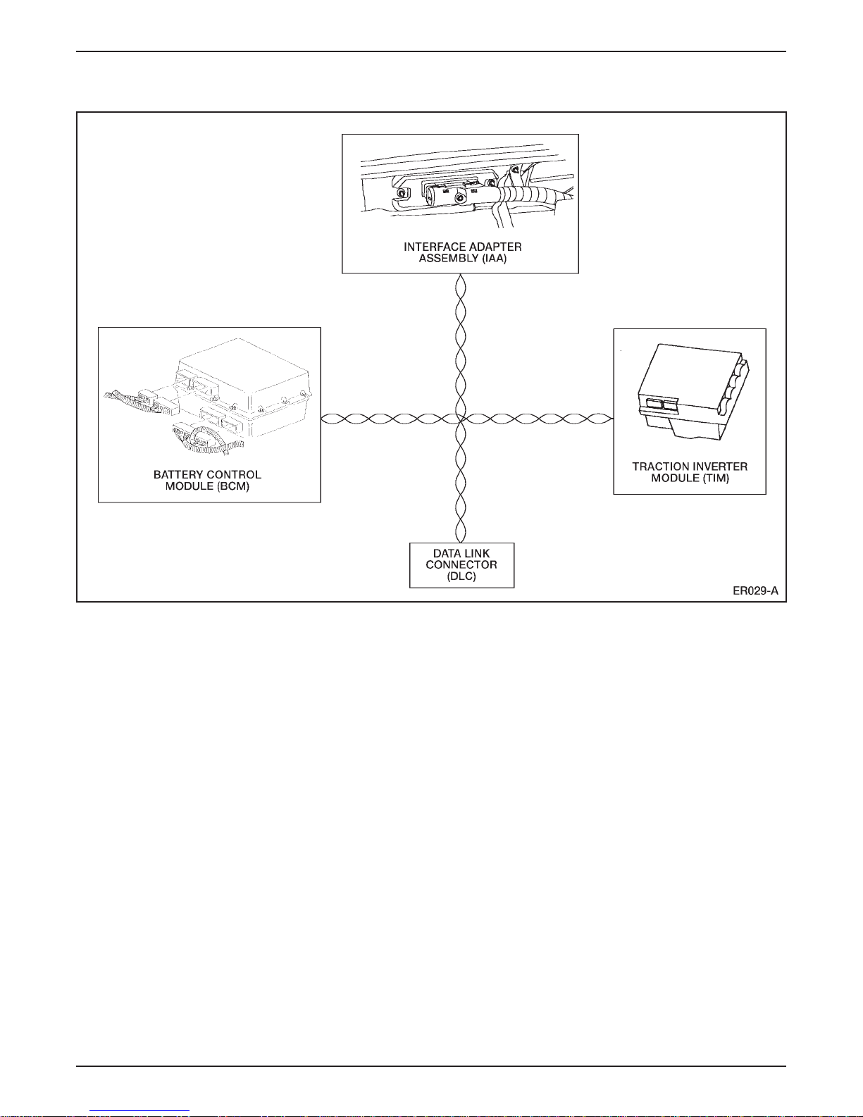
LESSON 1: VEHICLE OVERVIEW
NETWORKS AND MULTIPLEXING
Multiplexing System
• A network is an electronic system composed of control module(s)
and/or diagnostic tester (scan tool) that are connected with at least
one wire. This hardware allows the modules to communicate with
each other.
• The use of networks provides several benefits. These include:
– Input sensor information can be shared between control
modules. This means that they do not have to be hard wired into
each module that requires the data they provide.
– Complex vehicle actions requiring the participation of more than
one module can be performed.
– Improved diagnostic capability is available over the network.
1-42 1998 Ranger EV New Model Training
Page 51

LESSON 1: VEHICLE OVERVIEW
• Multiplexing is an operating strategy where control modules can
communicate with each other during normal vehicle operation.
• Multiplexing only occurs over the J1850 network.
• Modules that are multiplexed use the J1850 network and standard
corporate protocol (SCP) to communicate (a protocol is a type of
computer language).
• The International Standard Organization (ISO) 9141 network is
NOT a multiplexed network.
• The ISO 9141 network is only used for diagnostic purposes and is
not active during normal vehicle operation.
• In order for the ISO 9141 network to be active, a scan tool must be
connected to the network.
• The Electric Ranger has both a J1850 (SCP) and an ISO 9141
network.
• The J1850 (SCP) network consists of:
– a twisted pair of connecting wires (known as a data bus) in the
wiring harness (Circuits 914 and 915).
– traction inverter module (TIM).
– battery control module (BCM).
– interface adapter assembly (IAA).
– data link connector (DLC) (located next to the steering column).
• The ISO 9141 network consists of:
– a single wire data bus (circuit 70).
– anti-lock brake system (ABS) module.
– central timer module (CTM).
– electronic crash sensor (ECS) module.
– DLC.
• Diagnostics for both networks is accessed through the DLC using
New Generation STAR (NGS) Tester (covered in Lesson 5).
1998 Ranger EV New Model Training 1-43
Page 52
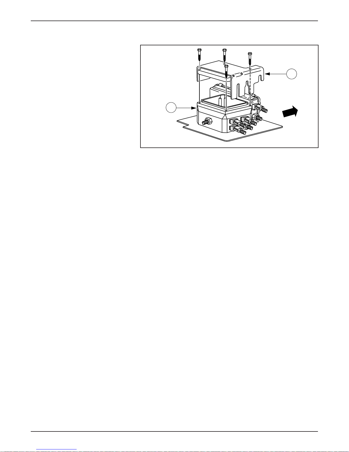
LESSON 1: VEHICLE OVERVIEW
HIGH VOLTAGE INTERLOCKS
High Voltage Interlocks
• High voltage interlocks help prevent electrical accidents by
disabling high voltage power when:
A
B
ER030-A
– connectors are disconnected.
– the top cover (A) of the high voltage power distribution box (B)
is removed.
• The Electric Ranger has interlocks on the following components
and wiring:
– The high voltage power distribution box cover.
– The high voltage connector from the traction battery to the high
voltage power distribution box.
– The high voltage connector from the traction battery to the TIM.
1-44 1998 Ranger EV New Model Training
Page 53
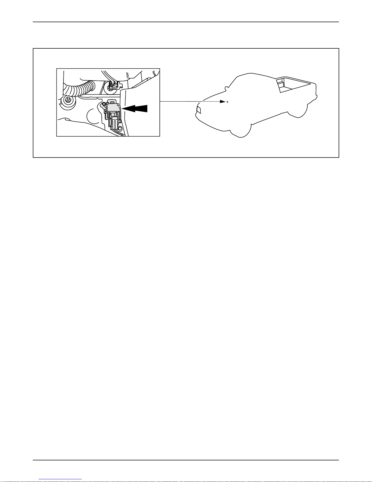
INERTIA SHUTOFF SWITCH
Inertia Shutoff Switch Location
LESSON 1: VEHICLE OVERVIEW
ER031-A
• The inertia shutoff switch (arrow) is located above the carpet line
and below the evaporator assembly on the passenger side of the
vehicle.
• The inertia shutoff switch on the Electric Ranger performs a similar
function as the inertia shutoff switch on the gasoline-powered
Ranger.
– On both vehicles, the inertia shutoff switch disables the vehicle
powertrain in the case of an accident.
– On the gasoline-powered Ranger, the inertia shutoff switch
disables the fuel pump.
– On the Electric Ranger, the inertia shutoff switch interrupts the
high voltage power to the vehicle systems.
• The POWER RESET lamp illuminates whenever the inertia shutoff
switch is triggered.
– The reset button is located on top of the inertia shutoff switch.
Emergency Power Off (EPO)
• The EPO is a fail-safe system designed to safeguard against
personal injury and prevent vehicle damage.
1998 Ranger EV New Model Training 1-45
• EPO is activated when the inertia shutoff switch is triggered or a
high voltage interlock is disconnected.
– An EPO signal is sent to disable all high voltage loads and shut
down the vehicle.
– TIM, BCM, and IAA can initiate an EPO signal.
Page 54
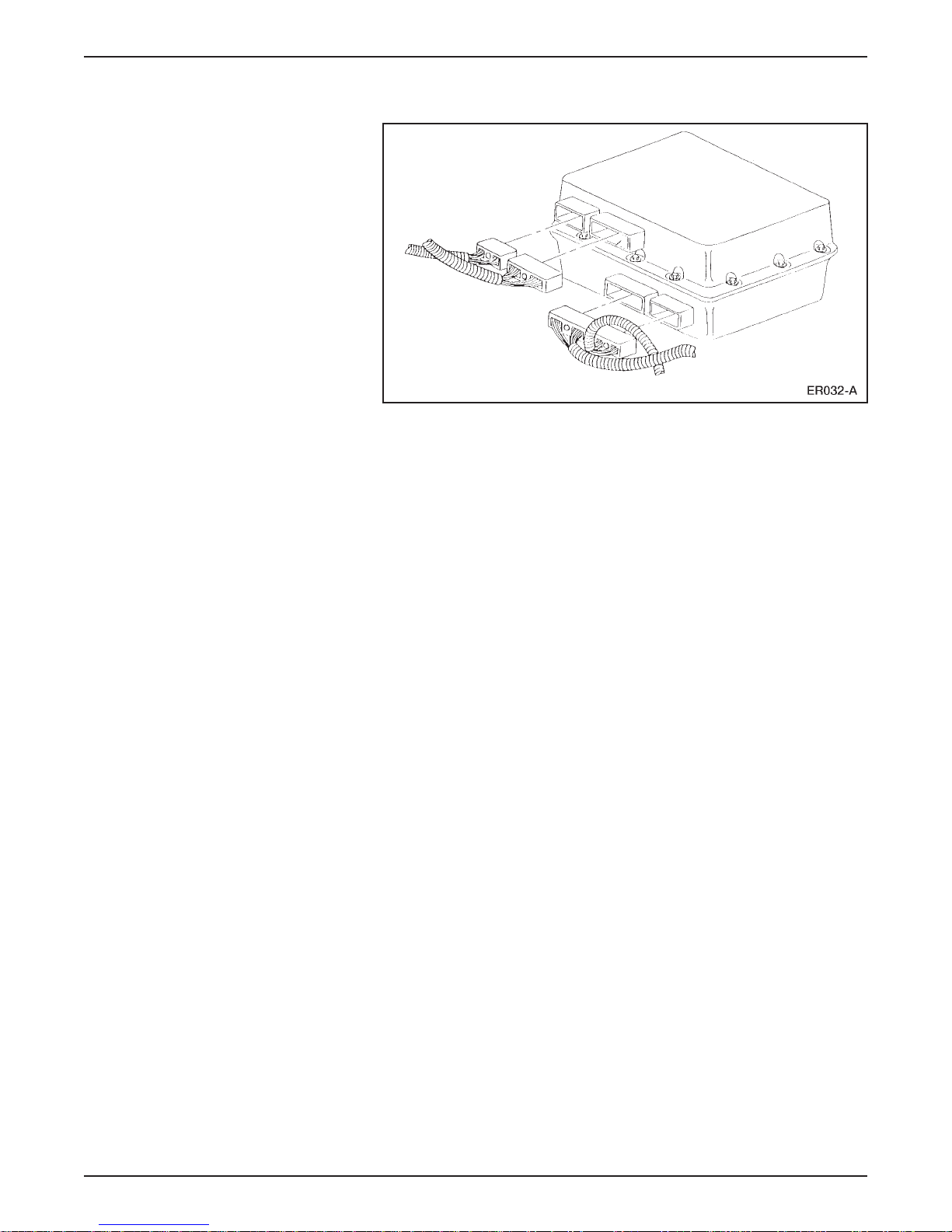
LESSON 1: VEHICLE OVERVIEW
CURRENT LEAKAGE DETECTION
Current Leakage Detection
• The Electric Ranger uses a current leakage detection system to
monitor the integrity of the electrical system.
• The BCM monitors the high voltage system for current leakage by
checking the DC circuitry for a low impedance path.
• Current leakage detection is performed by relays, leakage current
shunts and current limiting resistors within the BCM.
• This internal circuitry interfaces with either terminal of the traction
battery to measure impedance path between the terminal and the
vehicle chassis.
• If the BCM detects severe leakage, the electric hazard warning
lamp in the instrument cluster will illuminate.
NOTE: If the electric hazard warning lamp remains illuminated after
lamp prove out, service the vehicle.
1-46 1998 Ranger EV New Model Training
Page 55
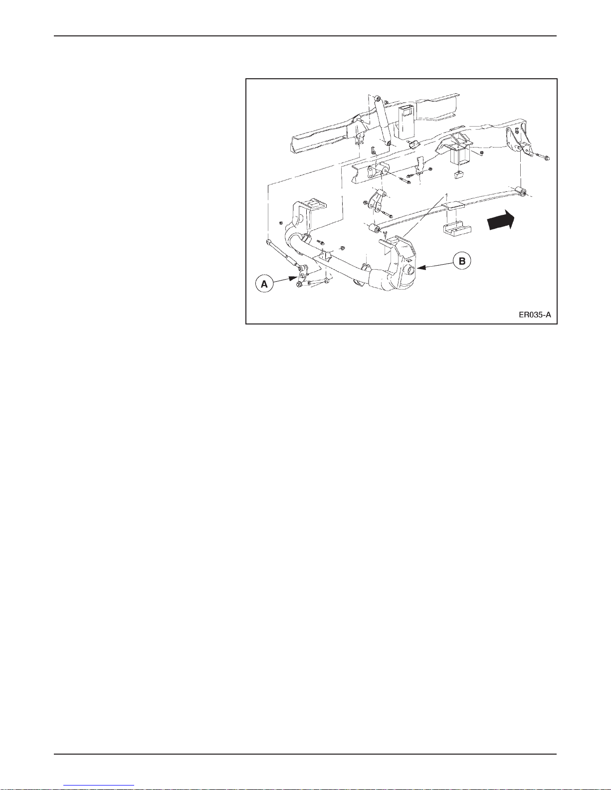
LESSON 1: VEHICLE OVERVIEW
SUSPENSION SYSTEM
Rear Suspension Components
• The rear suspension system is designed specifically for the Electric
Ranger.
• The DeDion rear axle (B) consists of:
– a thick-walled aluminum tube.
– sand-cast aluminum ends with Bearing carriers and spring seats.
– aluminum ends that are welded to the aluminum tube.
• The rear axle utilizes a Watts linkage (A) for handling and control.
• The rear shock absorbers and jounce bumper brackets are unique.
• Composite single-rate leaf springs are used for weight reduction.
• Carryover Ranger spring mounts and shackles are used.
Front Suspension System
• The front suspension consists of Ranger 4x4 control arms and
modified Explorer 4x2 steering knuckle and spindle assemblies.
1998 Ranger EV New Model Training 1-47
• A unique stabilizer bar is tuned for proper roll stiffness.
• Unique torsion bars and shock absorbers attach to carryover
Ranger mounts.
Page 56
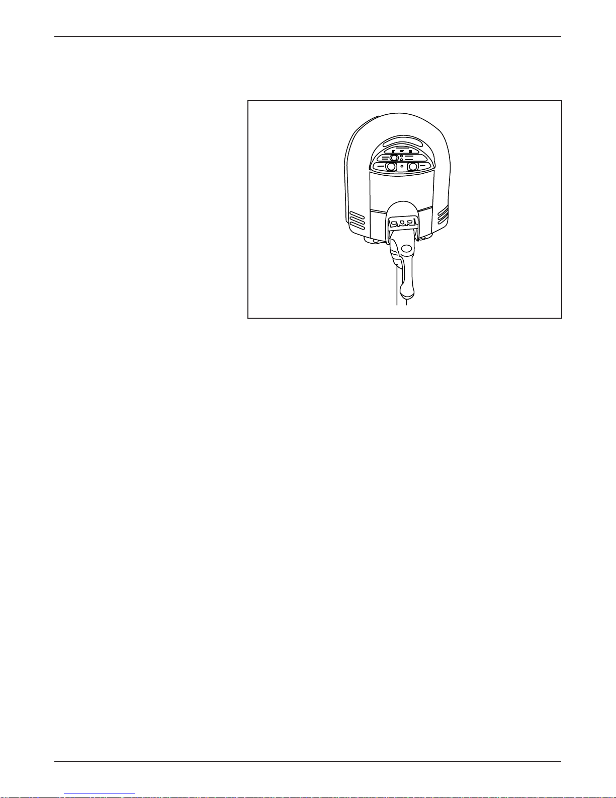
LESSON 1: VEHICLE OVERVIEW
TRACTION BATTERY CHARGING COMPONENTS
Power Control Station (PCS)
ER036-A
Power Control Station (PCS)
• The Electric Ranger’s traction battery is charged by an off-board
power control station (PCS).
• The PCS requires 240-volt 40 amp AC service.
• When connection is made from the PCS to the vehicle:
– self test and vehicle confirmation tests are initiated.
– if the system is operational, the green charging light will
illuminate on the PCS.
– the green charging light indicates the self test and the vehicle
confirmation tests are compete and charging has begun.
– the charger fans will start cooling the on-vehicle charger
approximately four minutes after the charging light illuminates
steadily.
1-48 1998 Ranger EV New Model Training
Page 57

LESSON 1: VEHICLE OVERVIEW
• If the green START light goes out and the amber CHARGE
INTERRUPT light illuminates:
– operation has been discontinued by the Class A ground fault
detection system.
– due to the high sensitivity of this system, the charge operation
will be shut down if either the charge cord plug or the charge
inlet is wet or damp.
• Press the STOP button to reset the system.
– If further attempts are unsuccessful, it is likely that a ground
fault exists.
– If a ground fault exists, it must be repaired to continue the
charging operation.
• Complete charging procedure is covered in Lesson 2.
1998 Ranger EV New Model Training 1-49
Page 58
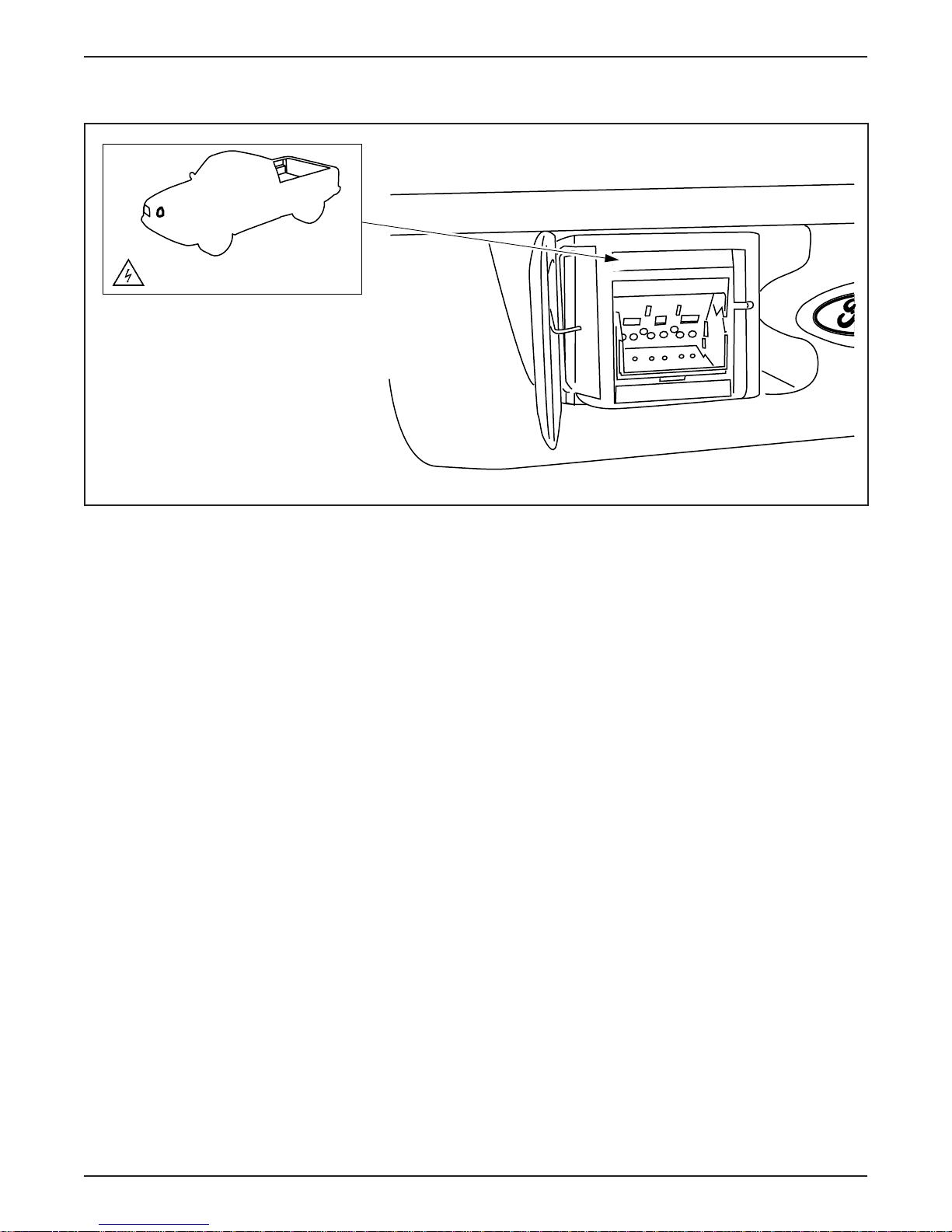
LESSON 1: VEHICLE OVERVIEW
Charge Inlet
HIGH VOLTAGE COMPONENT
ER037-A
Charge Inlet
• The charge inlet is equivalent to the fuel filler port on a gasoline-
powered vehicle.
• The Electric Ranger receives power in the form of 240-volt
AC current.
• An EV industry standard plug fits into the charge inlet.
– Located between the headlights behind a grille access door.
• The high voltage wiring that connects the charge inlet to the
on board battery charger is energized only during charging.
1-50 1998 Ranger EV New Model Training
Page 59
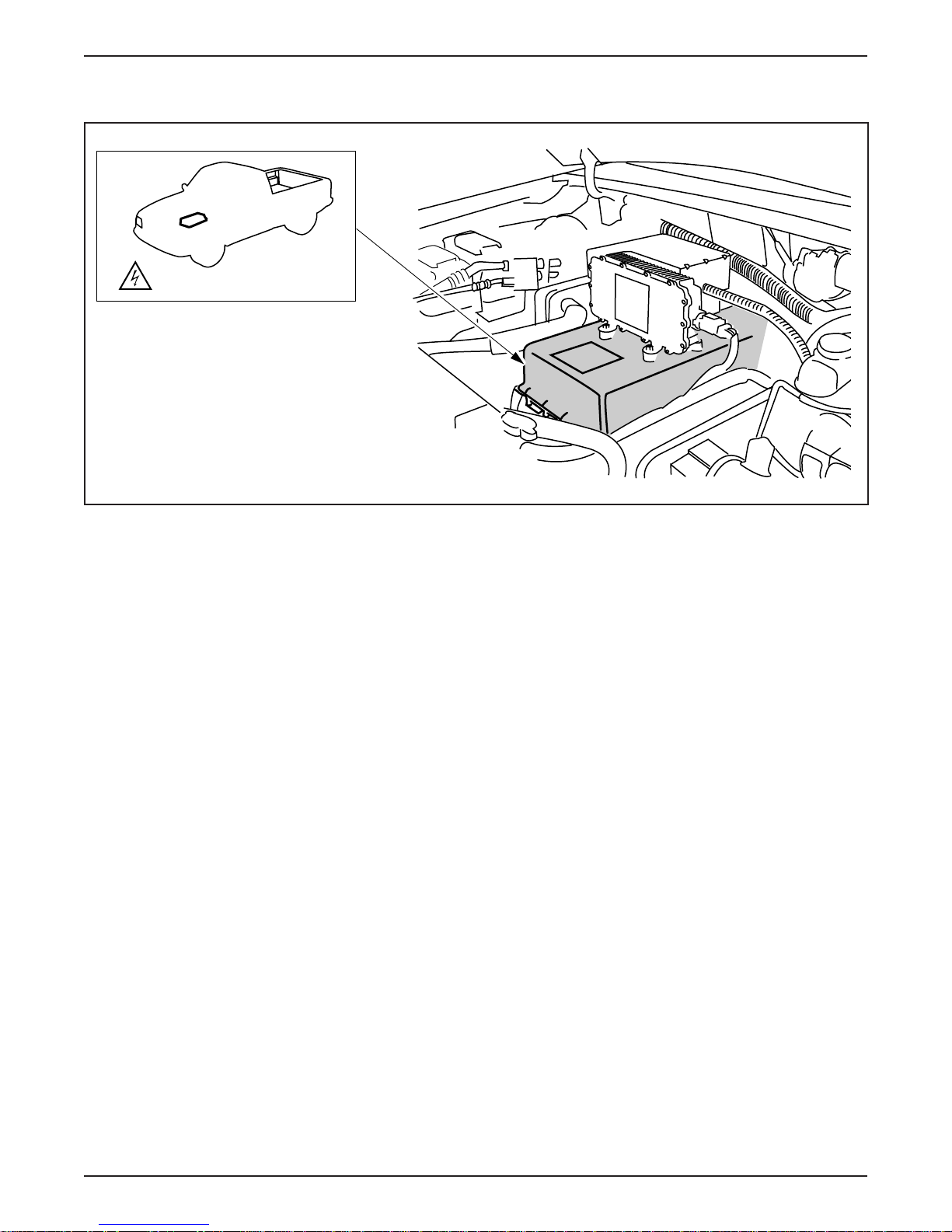
Battery Charger
HIGH VOLTAGE COMPONENT
LESSON 1: VEHICLE OVERVIEW
ER038-A
Battery Charger
• The on-board battery charger (arrow) is located in the underhood
compartment beneath the high voltage power distribution box.
• The on-board battery charger receives 240-volt 40 amp AC current
from the power control station (PCS) and converts it into DC
current.
• The on-board battery charger operates only with a charger cord
plugged into the charge inlet.
– The vehicle cannot be started or driven with the charger cord
attached to the charge inlet.
• Internal fans provide cooling during battery charger operation.
1998 Ranger EV New Model Training 1-51
Page 60
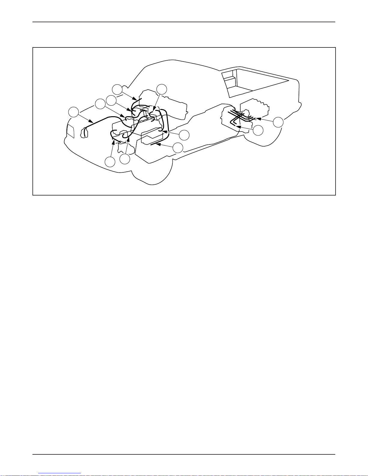
LESSON 1: VEHICLE OVERVIEW
HIGH VOLTAGE WIRING
H
High Voltage Wiring
K
J
I
F
G
A
B
D
E
C
ER039-A
• All high voltage wiring is covered with color-coded with orange
convolute.
• High voltage wiring connects the following components:
A. From battery charger to high voltage power distribution box
B. From TIM to motor/transaxle
C. From traction battery to TIM
D. From high voltage power distribution box to DC/DC converter
E. From traction battery to high voltage power distribution box
F. From high voltage power distribution box to power steering
controller assembly
G. From A/C inverter motor controller to A/C compressor
H. From charge inlet to battery charger
I. From high voltage power distribution box to A/C inverter
motor controller
J. From high voltage power distribution box to PTC switching
module
K. From PTC switching module to PTC heater
• The illustrations on the following pages provide a reference for the
high voltage cables on the Electric Ranger.
1-52 1998 Ranger EV New Model Training
Page 61
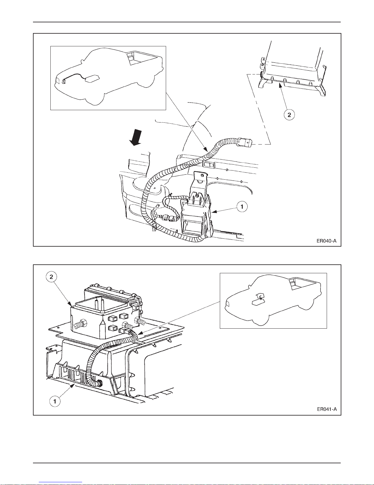
LESSON 1: VEHICLE OVERVIEW
High Voltage Wiring from Charge Inlet (1) to Battery Charger (2)
High Voltage Wiring from Battery Charger (1) to High Voltage Power Distribution Box (2)
1998 Ranger EV New Model Training 1-53
Page 62
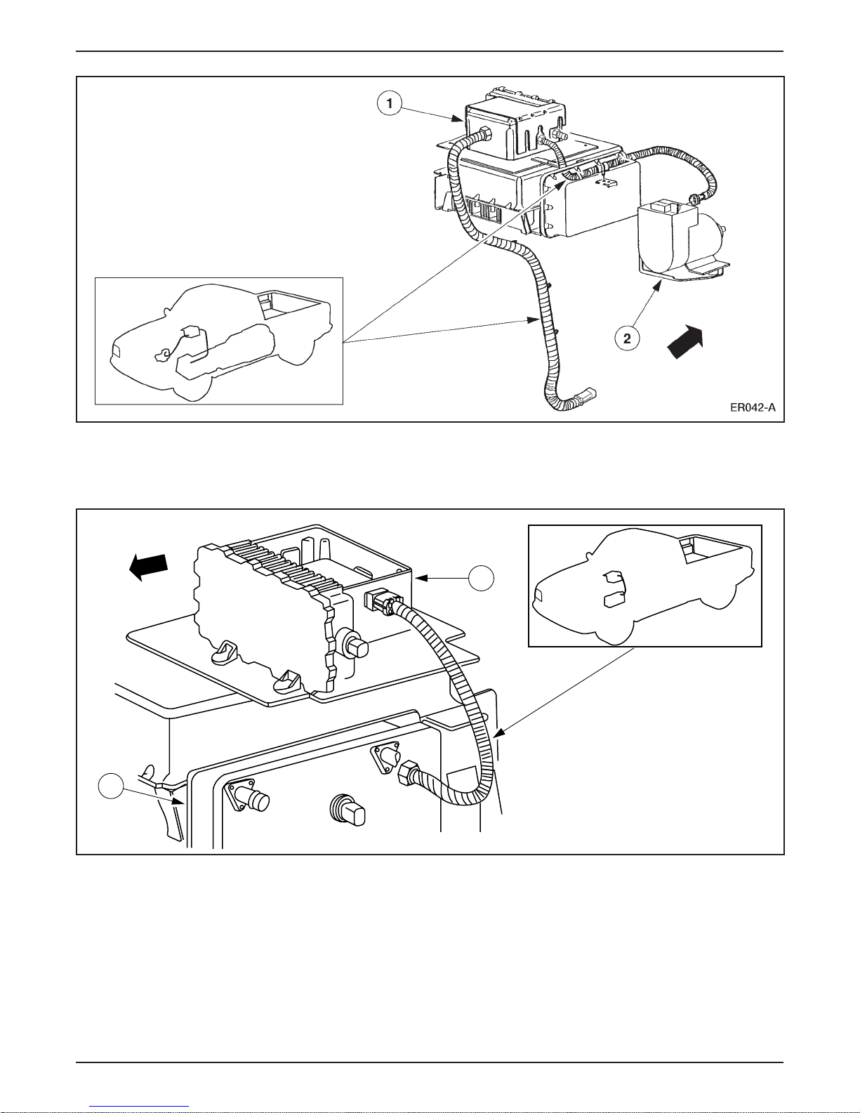
LESSON 1: VEHICLE OVERVIEW
High Voltage Wiring from High Voltage Power Distribution Box (1) to Traction Battery
High Voltage Wiring from High Voltage Power Distribution Box (1) to
Power Steering Controller Assembly (2)
3
4
High Voltage Wiring from High Voltage Power Distribution Box (3) to DC/DC Converter (4)
ER043-A
1-54 1998 Ranger EV New Model Training
Page 63
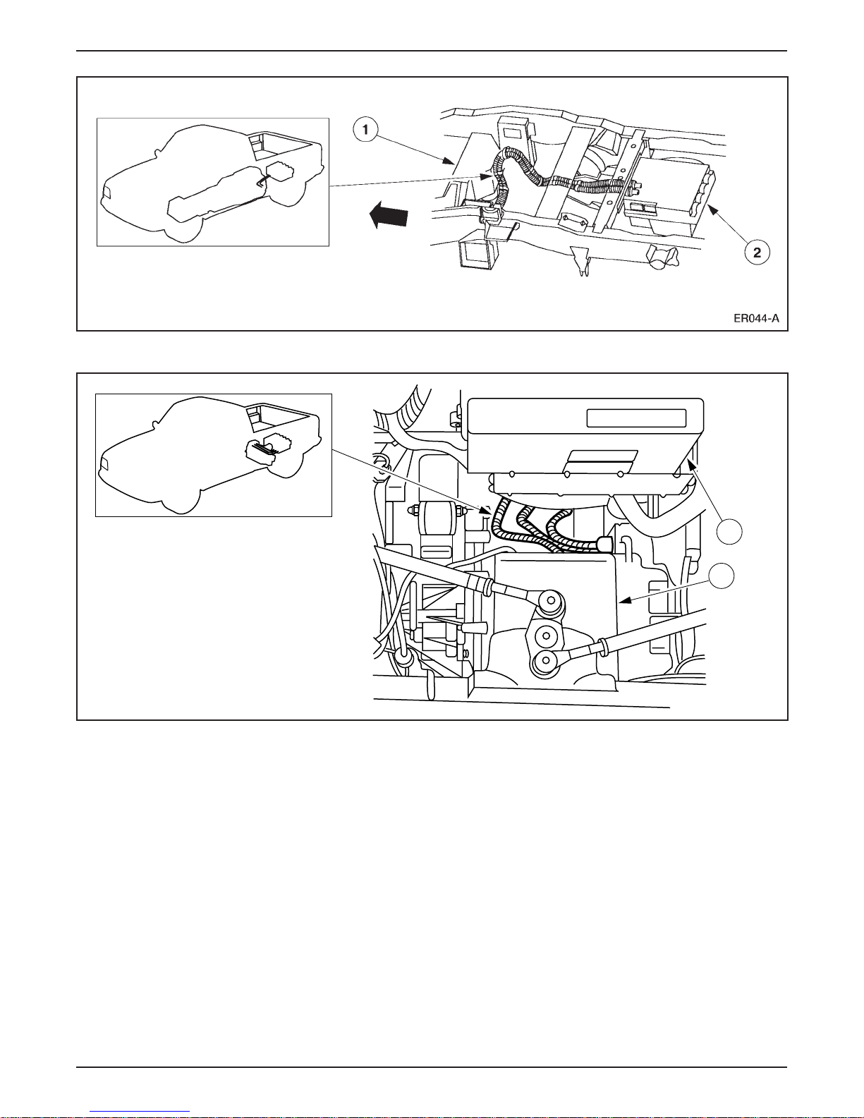
High Voltage Wiring from Traction Battery (1) to TIM (2)
LESSON 1: VEHICLE OVERVIEW
High Voltage Wiring from TIM (3) to Motor/Transaxle (4)
3
4
ER045-A
1998 Ranger EV New Model Training 1-55
Page 64

LESSON 1: VEHICLE OVERVIEW
1
2
High Voltage Wiring from High Voltage Power Distribution Box (1) to PTC Switching Module (2)
ER046-A
High Voltage Wiring from PTC Switching Module (3) to PTC Heater
1-56 1998 Ranger EV New Model Training
Page 65
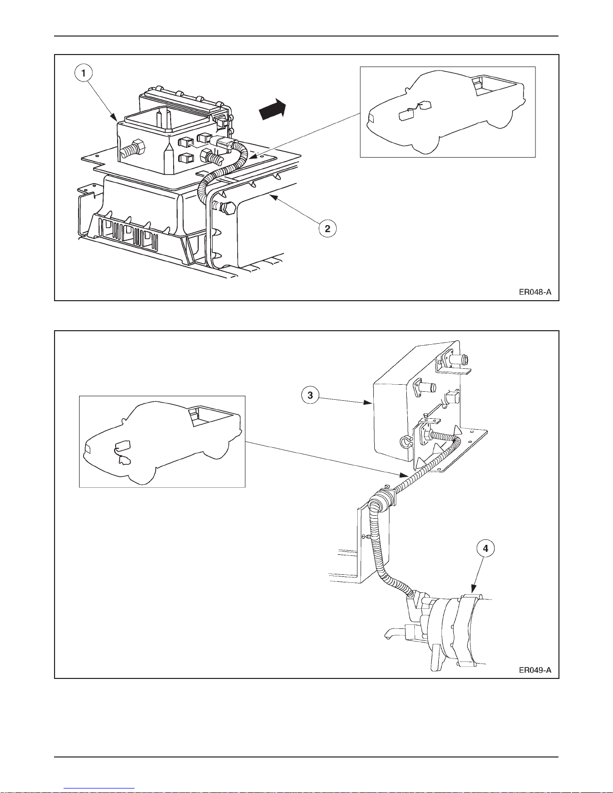
LESSON 1: VEHICLE OVERVIEW
High Voltage Wiring from High Voltage Power Distribution Box (1) to A/C Inverter Motor Controller (2)
High Voltage Wiring from A/C Inverter Motor Controller (3) to A/C Compressor (4)
1998 Ranger EV New Model Training 1-57
Page 66

LESSON 1: VEHICLE OVERVIEW
NOTES
1-58 1998 Ranger EV New Model Training
Page 67
LESSON 1: VEHICLE OVERVIEW
1
2
4
3
5
EV151-A
6
8
9
10
11
12
13
14
15
7
16
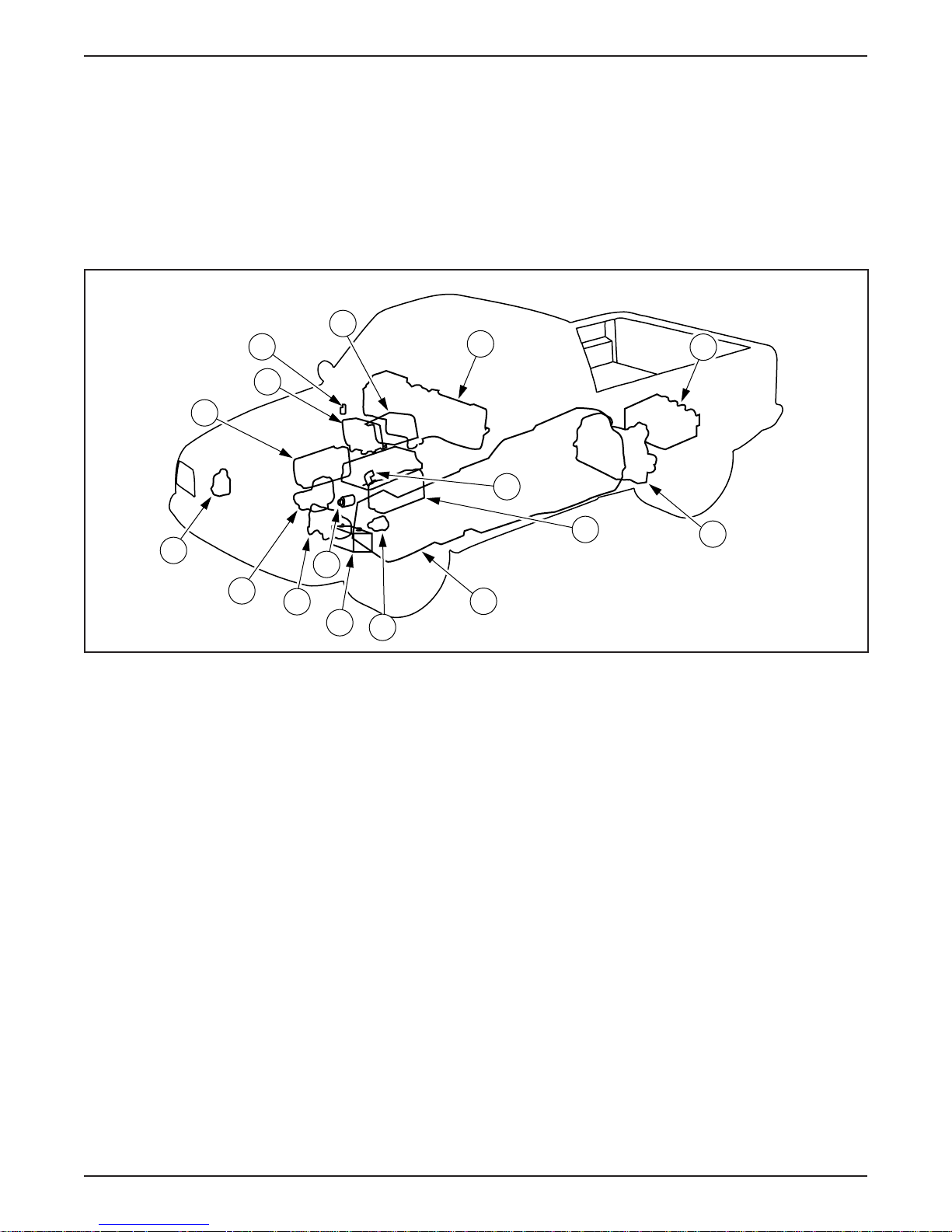
ACTIVITY 1 – VEHICLE OVERVIEW – WORKSHEET A
COMPONENT LOCATION
STUDENT ANSWER SHEET
OBJECTIVE: To identify the location of EV Ranger components.
DIRECTIONS: Go to the classroom vehicles. You will find the components listed below have tags attached to
them. Write the letter/number on the tag that is attached to each of the listed components.
High Voltage Components
_____ A/C Compressor (H)
_____ A/C Inverter Motor Controller
_____ Charge Inlet
_____ DC/DC Converter
_____ Motor/Transaxle (H)
_____ High Voltage Power Distribution Box
_____ Power Steering Controller Assembly
_____ PTC Heater Core (inside of Chamber
1998 Ranger EV New Model Training 1-59
Assembly-Heater Plenum)
_____ PTC Switching Module
_____ Traction Battery (includes BCM and
Contactor Box) (H)
_____ Battery Charger
_____ Traction Inverter Module (TIM) (H)
_____ Vacuum Pump
_____ Coolant Pump
_____ Auxiliary Battery
_____ Inertia Switch
END OF WORKSHEET A
Page 68

LESSON 1: VEHICLE OVERVIEW
ACTIVITY 1 – VEHICLE OVERVIEW – WORKSHEET B
COMPONENT FUNCTION EXERCISE
STUDENT ANSWER SHEET
OBJECTIVE: To identify the function of the Electric Ranger components and systems.
DIRECTIONS: Match the listed items with the correct definitions:
1. Interface Adapter Assembly (IAA)
2. Regenerative Braking System (RBS)
3. DC/DC Converter
4. Vacuum Pump
5. Contactor Box
6. PTC Switching Module
7. Traction Inverter Module (TIM)
_____ manages all functions of the traction battery.
_____ charges the 12-volt battery.
_____ allows module to module communication during normal vehicle operation.
_____ converts high voltage DC into three-phase AC.
_____ interacts directly with the heating and braking system.
_____ replaces the accelerator cable.
8. Battery Charger
9. Electronic Throttle Control
10. Battery Control Module (BCM)
11. Auxiliary Battery
12. Multiplexing System
13. Inertia Switch
_____ controls the PTC heating system.
_____ is cooled by internal cooling fans.
_____ contains two relays and two resistors for high voltage circuit precharging
_____ converts vehicle kinetic energy into electrical energy.
_____ is located directly in front of the high voltage power distribution box.
_____ powers the lighting system.
_____ interrupts power in the event of a collision.
END OF WORKSHEET B
1-60 1998 Ranger EV New Model Training
Page 69

LESSON 1: VEHICLE OVERVIEW
ACTIVITY 1 – VEHICLE OVERVIEW – WORKSHEET C
SAFETY FEATURE IDENTIFICATION
STUDENT ANSWER SHEET
OBJECTIVES: To describe the safety features found on the Electric Ranger.
DIRECTIONS: Select the correct response for each statement or question.
1. The inertia shutoff switch is located:
A. Beside the 12-volt battery in the underhood compartment.
B. Below the evaporator assembly in the passenger compartment.
C. Next to the diagnostic connector in the underhood compartment.
D. Above the TIM and close to the left rear fender.
2. When does the electric hazard warning lamp illuminate?
A. When the driver’s key is turned to the ON position (lamp prove-out).
B. When a high level of current leakage is detected.
C. When a high voltage interlock is disconnected.
D. All of the above.
3. What color identifies a high voltage cable?
A. Red.
B. Orange.
C. Yellow.
D. All of the above.
4. Which of the following is not equipped with a high voltage interlock?
A. The cover of the high voltage power distribution box.
B. The connector from the traction battery to the high voltage power distribution box (4-pin connector).
C. The connector from the traction battery to the TIM (2-pin connector).
D. The cover of the traction battery.
5. High voltage components are identified by:
A. Identification tags.
B. Red color coding.
C. Warning labels.
D. Plastic insulation.
1998 Ranger EV New Model Training 1-61
END OF WORKSHEET C
Page 70

NOTES
Page 71

LESSON 2: VEHICLE OPERATION
TECHNICIAN OBJECTIVES
• Describe vehicle operation.
• Identify instrument cluster components and functions.
• Describe the economy mode.
• Describe traction battery charging procedures.
CONTENTS
• Vehicle Operation
• Instrument Cluster Gauges
• Instrument Cluster Warning Lamps
• Economy Mode
• Traction Battery Charging
• Driver Response to an Emergency Situation
• Activity 2 – Vehicle Familiarization
• Worksheet D – Operating Characteristics of the Electric Ranger
• Worksheet E – Warning and Indicator Lamps
• Worksheet F – Instrument Gauges and Lights
1998 Ranger EV New Model Training 2-1
Page 72
LESSON 2: VEHICLE OPERATION
VEHICLE OPERATION
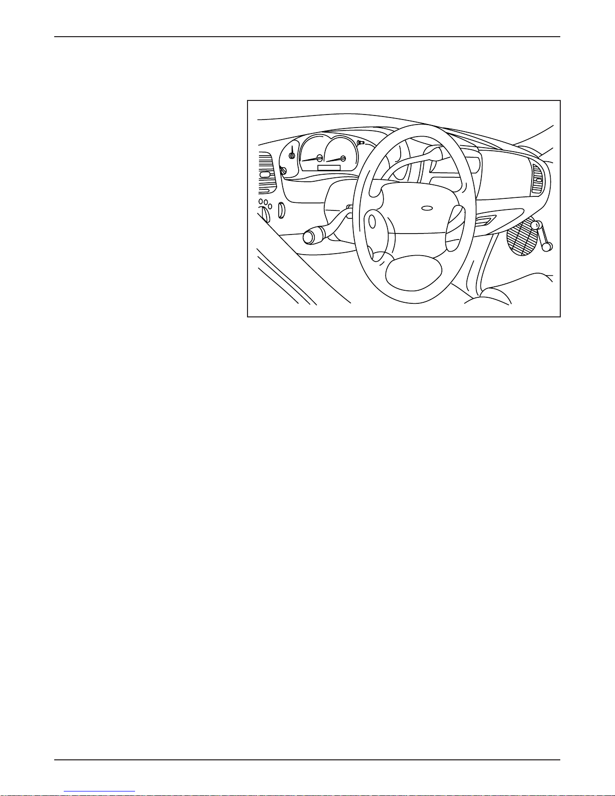
Vehicle Controls
ER051-A
Vehicle Controls
• Driving the Electric Ranger is similar to operating a gasoline-
powered vehicle.
• The key positions are the same as other Ford vehicles (positions are
listed from full rearward to full forward):
– ACC
– LOCK
– OFF
–ON
– START
• The major controls are operated in the same manner as other
Ford vehicles.
– gear selector lever (except for unique economy mode)
– accelerator pedal
2-2 1998 Ranger EV New Model Training
– brake pedal
– parking brake
Page 73

LESSON 2: VEHICLE OPERATION
• The instrument cluster has several new gauges and warning lamps
(covered later in this lesson).
• When the driver key is turned to the START position, there is no
starter motor noise (although the vehicle is activated).
• The Electric Ranger “creeps” forward like a gasoline-powered
vehicle with an automatic transmission that is in gear (after the
vehicle is “started” and the key remains in the ON position foot
off brake).
• During deceleration, a higher drag is felt due to the regenerative
braking system (covered later in this lesson).
1998 Ranger EV New Model Training 2-3
Page 74
LESSON 2: VEHICLE OPERATION
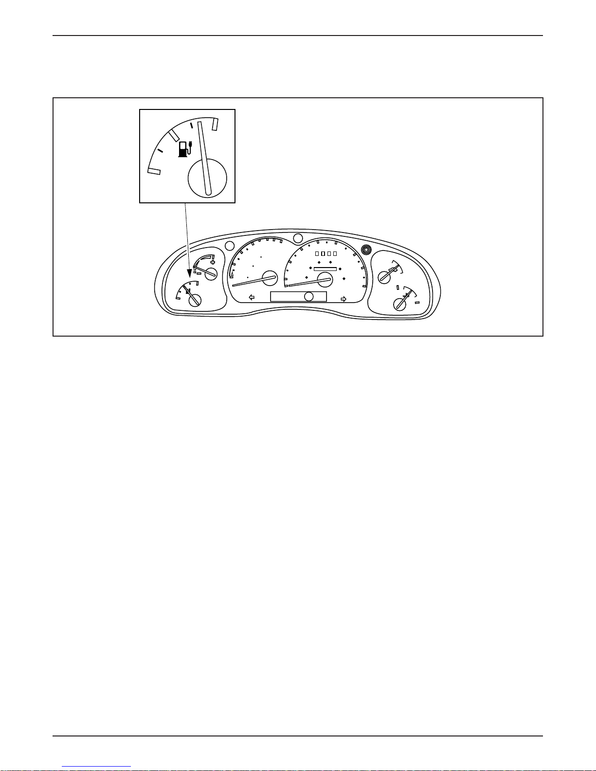
INSTRUMENT CLUSTER GAUGES
Battery State of Charge Gauge
F
E
0
6
100
4
0
ECON
F
E
MILES
DISTANCE
50
TO EMPTY
0
2
km
0
0
40
30
60 80
20
40
000000
20
10
MPH
P RNDE
50
60
100
70
120
80
km/h
ON
OFF
H
C
Battery State of Charge Gauge
ER052-A
• The Battery State of Charge Gauge is the equivalent of the fuel
gauge on a gasoline-powered vehicle.
– F is indicated when the traction battery is fully charged.
– E is indicated when the traction battery is discharged to the point
where additional operation will reduce traction battery life.
• The BCM monitors the percent of charge of each battery module
and calculates the average state of charge of the traction battery.
• The BCM sends battery state of charge information to the IAA
through the J1850 (SCP) network.
• The IAA uses the Battery State of Charge Gauge to indicate the
traction battery state of charge.
2-4 1998 Ranger EV New Model Training
Page 75
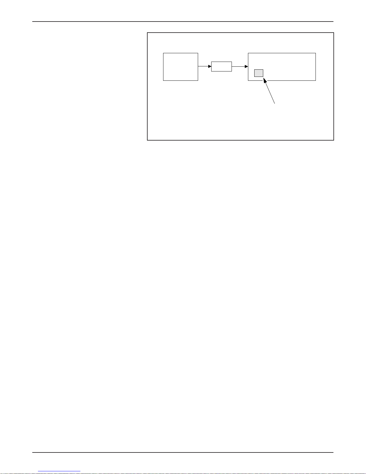
LESSON 2: VEHICLE OPERATION
BCM
IAA
INSTRUMENT CLUSTER
BATTERY STATE
OF CHARGE GAUGE
ER119-A
Battery State of Charge Gauge Inputs
NOTE: The POWER LIMIT and Low Fuel Warning Lamps flash
when the gauge reads empty. Vehicle performance will be extremely
limited at this point; the driver must pull over off the road (to the
shoulder) as quickly and safely as possible.
1998 Ranger EV New Model Training 2-5
Page 76
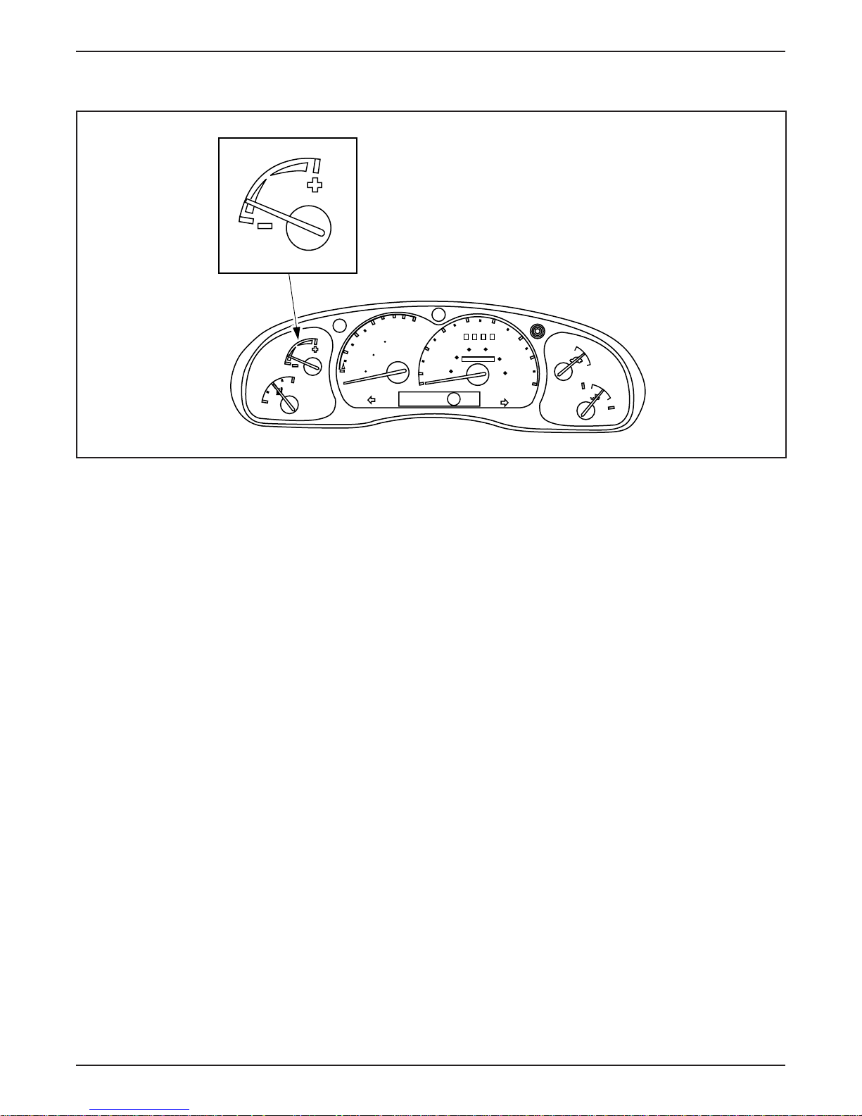
LESSON 2: VEHICLE OPERATION
ECON (Economy) Gauge
ECON
6
4
MILES
0
50
0
2
km
0
0
ECON
F
E
0
100
DISTANCE
TO EMPTY
P RNDE
40
40
60 80
000000
50
60
100
70
120
80
km/h
ON
OFF
H
C
30
20
20
10
MPH
ER053-A
ECON (Economy) Gauge
• The Economy Gauge not only shows the driver that his/her actions
affect vehicle range, but that driving more economically can
increase the vehicle range.
• The gauge reading reflects:
– drivetrain power usage.
– vehicle speed.
– climate control usage.
– regeneration effects.
• The needle will move toward the plus (+) sign (green band) when
the driver minimizes power usage or puts power back into the
vehicle.
• The needle will move toward the minus (-) sign (yellow band)
when the driver accelerates quickly or turns on loads that reduce
vehicle range.
2-6 1998 Ranger EV New Model Training
• The IAA monitors several inputs and uses this information to
control the ECON Gauge.
Page 77
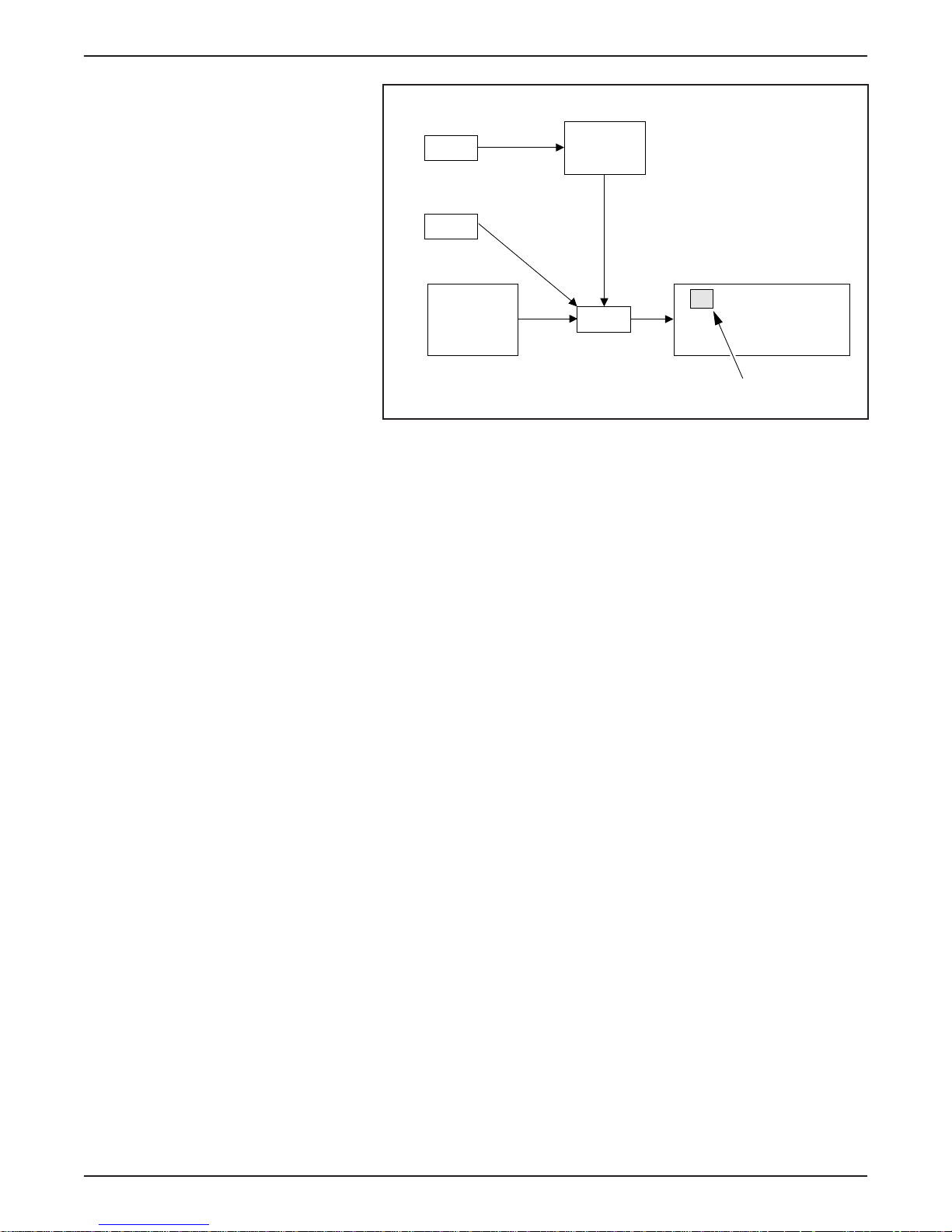
REAR ABS
SPEED SENSOR
HEATER/AC
LESSON 2: VEHICLE OPERATION
ABS
MODULE
INSTRUMENT CLUSTER
TIM
Economy Gauge Inputs
IAA
ECON GAUGE
ER120-A
1998 Ranger EV New Model Training 2-7
Page 78
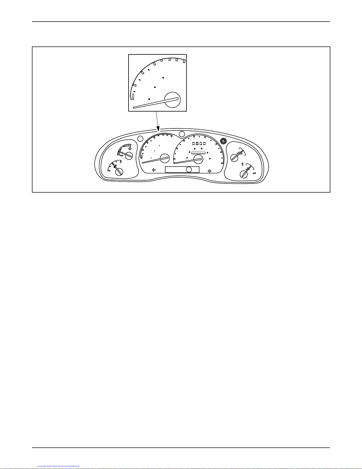
LESSON 2: VEHICLE OPERATION
DISTANCE TO EMPTY Gauge
6
100
4
0
50
0
2
km
0
0
MILES
0
6
100
4
0
MILES
DISTANCE
50
TO EMPTY
0
2
km
0
0
ECON
F
E
0
DISTANCE
TO EMPTY
P RNDE
40
40
000000
60 80
50
60
100
70
120
80
km/h
ON
OFF
H
C
30
20
20
10
MPH
ER054-A
DISTANCE TO EMPTY Gauge
• The DISTANCE TO EMPTY Gauge estimates the remaining
distance that can be traveled before the traction battery needs to be
recharged.
– This estimate is calculated by the BCM.
• The DISTANCE TO EMPTY Gauge is controlled by the IAA and
varies as driving conditions change.
• Some conditions that affect the DISTANCE TO EMPTY
Gauge are:
– city/highway driving.
– hilly terrain.
– climate control usage.
– driving habits.
• The BCM monitors power consumption and sends this information
to the IAA.
2-8 1998 Ranger EV New Model Training
• The IAA controls the DISTANCE TO EMPTY Gauge based on
this information.
Page 79
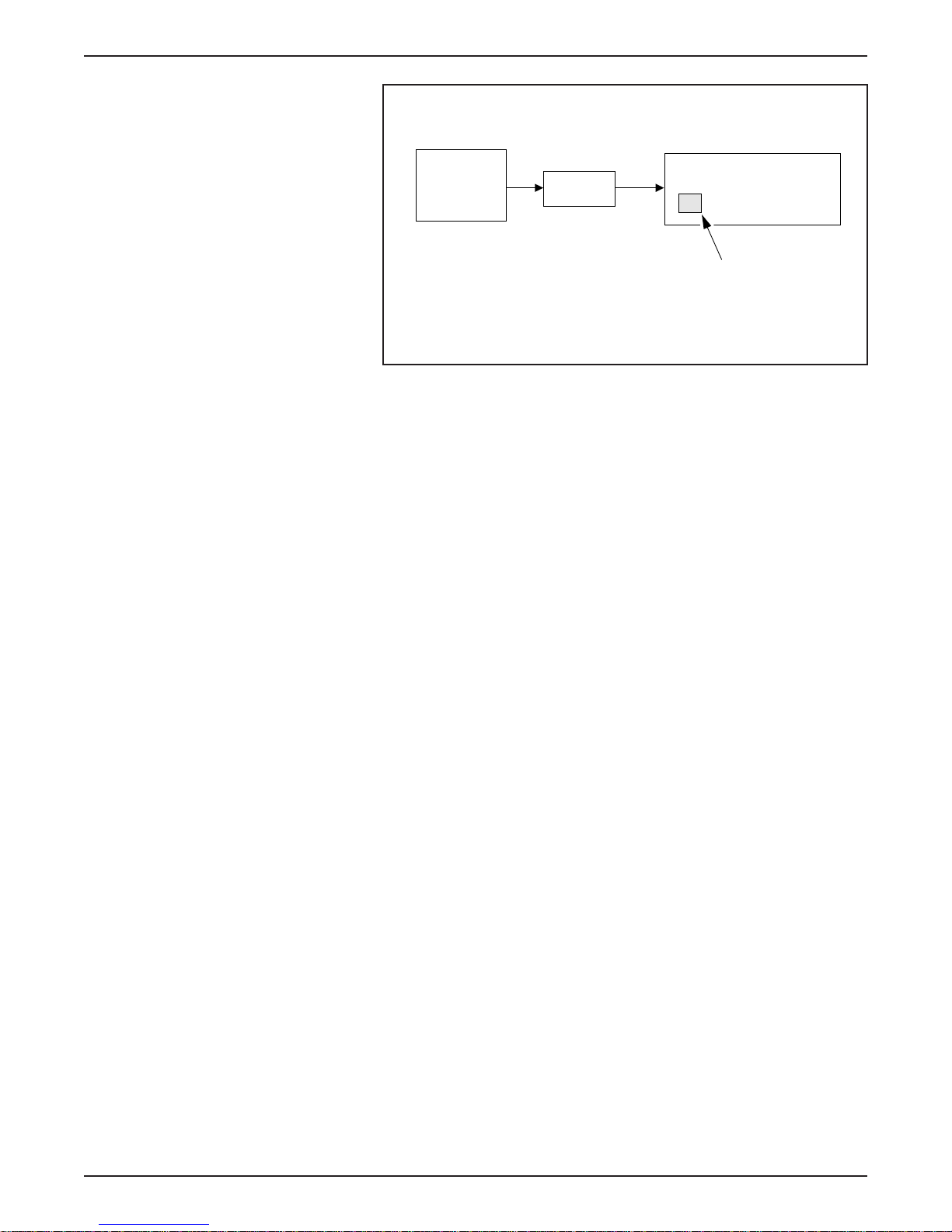
LESSON 2: VEHICLE OPERATION
INSTRUMENT CLUSTER
BCM
IAA
DISTANCE TO EMPTY Gauge Inputs
DISTANCE TO
EMPTY GAUGE
ER121-A
1998 Ranger EV New Model Training 2-9
Page 80
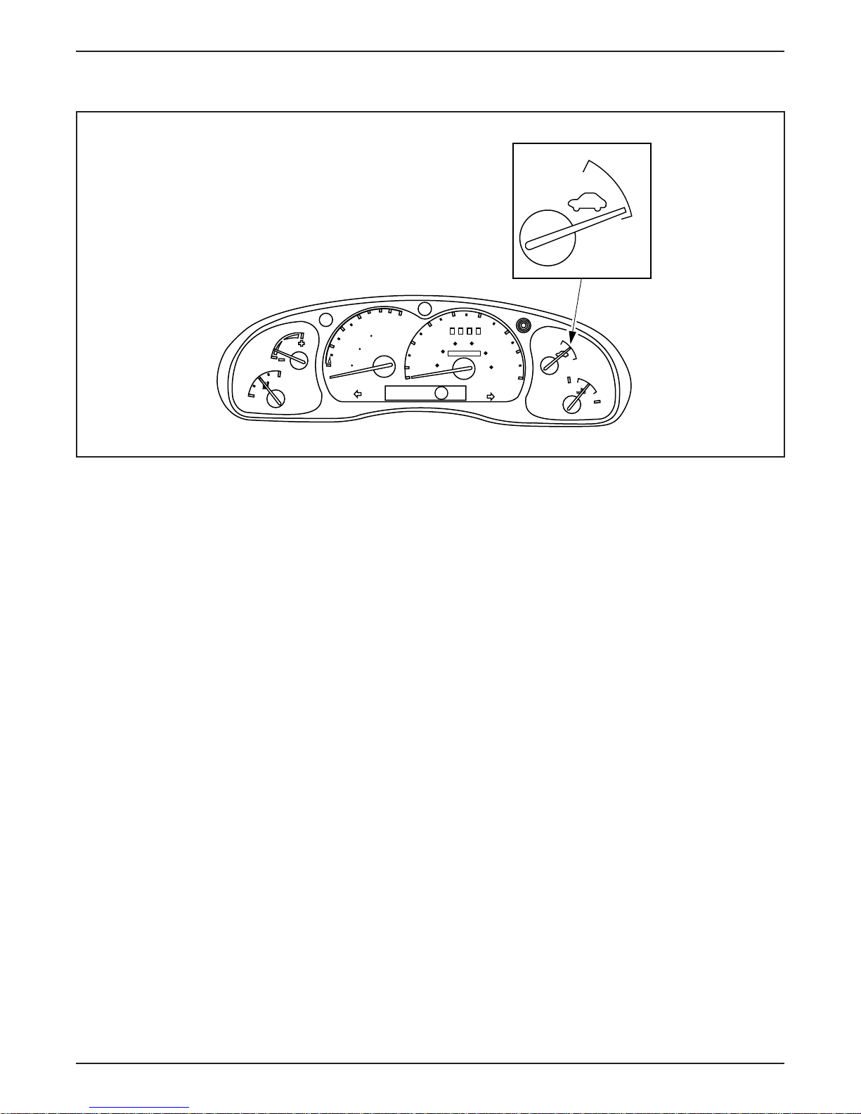
LESSON 2: VEHICLE OPERATION
Motor Enabled Gauge
0
6
100
4
0
ECON
F
E
MILES
DISTANCE
50
TO EMPTY
0
2
km
0
0
40
30
60 80
20
40
000000
20
10
MPH
P RNDE
ON
OFF
50
60
100
70
120
80
km/h
ON
OFF
H
C
ER055-A
Motor Enabled Gauge
• The Motor Enabled Gauge indicates that the vehicle is ready to be
driven.
• The needle will point to ON when the vehicle is enabled.
• The needle will return to OFF if the key is turned to the OFF
position or the powertrain becomes disabled.
• The IAA monitors the TIM and uses the Motor Enabled Gauge to
indicate the motor state (enabled or disabled).
2-10 1998 Ranger EV New Model Training
Page 81
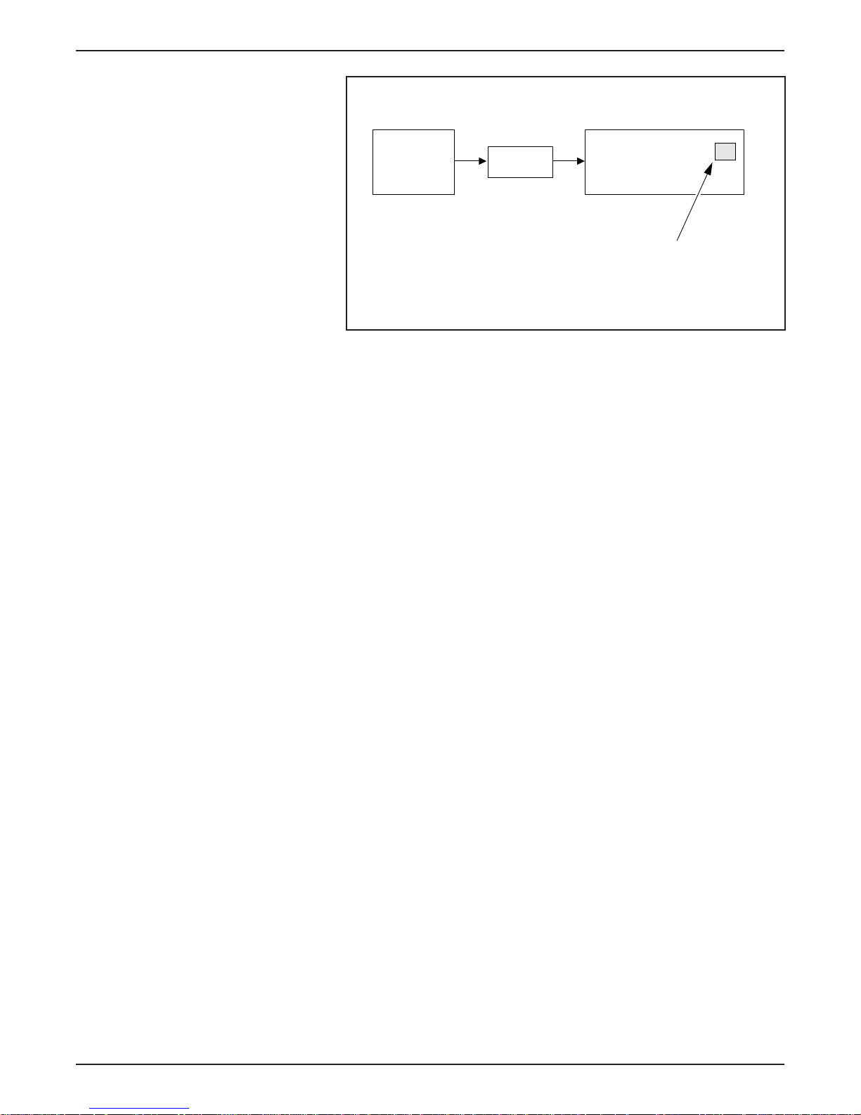
LESSON 2: VEHICLE OPERATION
INSTRUMENT CLUSTER
TIM
IAA
Motor Enabled Gauge Inputs
MOTOR ENABLED
GAUGE
ER122-A
1998 Ranger EV New Model Training 2-11
Page 82
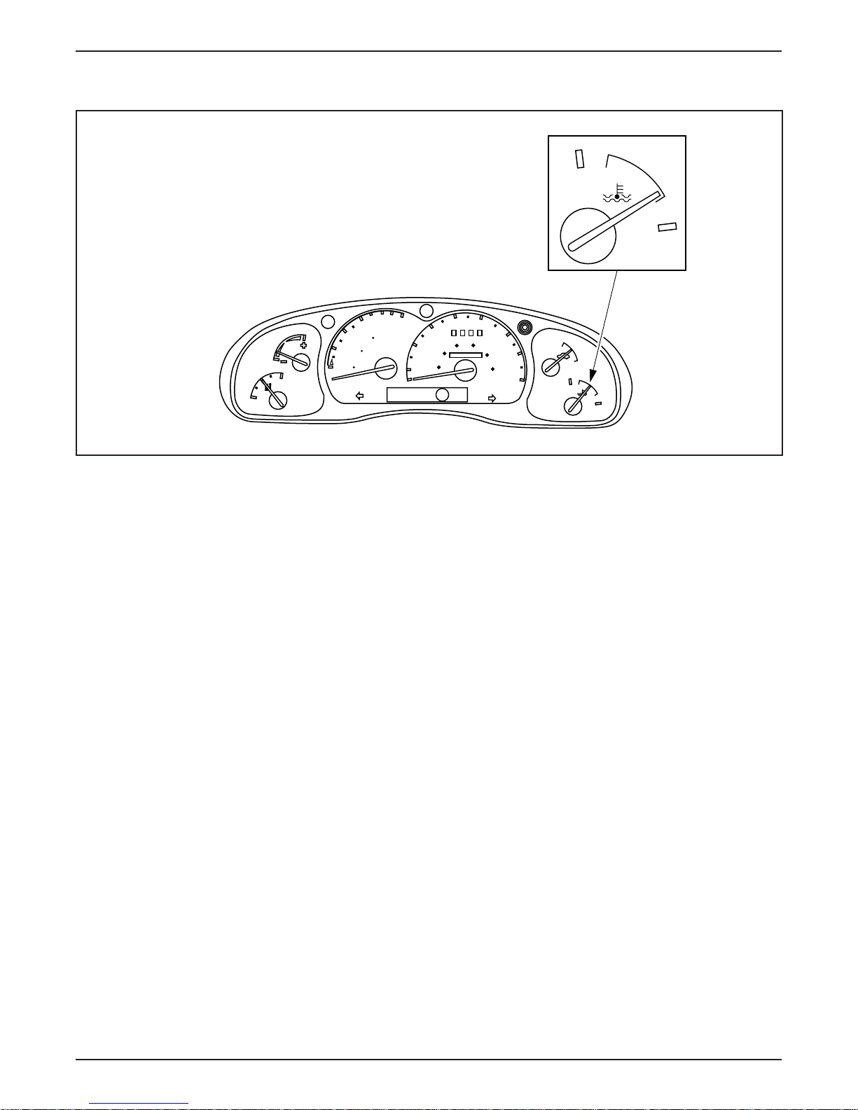
LESSON 2: VEHICLE OPERATION
Temperature Gauge
0
6
100
4
0
ECON
F
E
MILES
DISTANCE
50
TO EMPTY
0
2
km
0
0
40
30
60 80
20
40
000000
20
10
MPH
P RNDE
H
C
50
60
100
70
120
80
km/h
ON
OFF
H
C
ER056-A
Temperature Gauge
• The Temperature Gauge indicates the extreme temperature of
major components:
– Traction battery
– TIM
– Motor/transaxle
– Coolant
• If the temperature of any of these components is not within
desirable limits, the needle will move into the H (hot) or
C (cold) areas.
– The traction battery is the only component that can cause the
needle to move into the cold area.
– If the traction battery is too cold and another component is too
hot, the temperature gauge will display the hot condition.
• The IAA monitors systems that produce heat and uses the
Temperature Gauge to indicate an overheating condition or
a cold condition in the case of the traction battery.
2-12 1998 Ranger EV New Model Training
Page 83
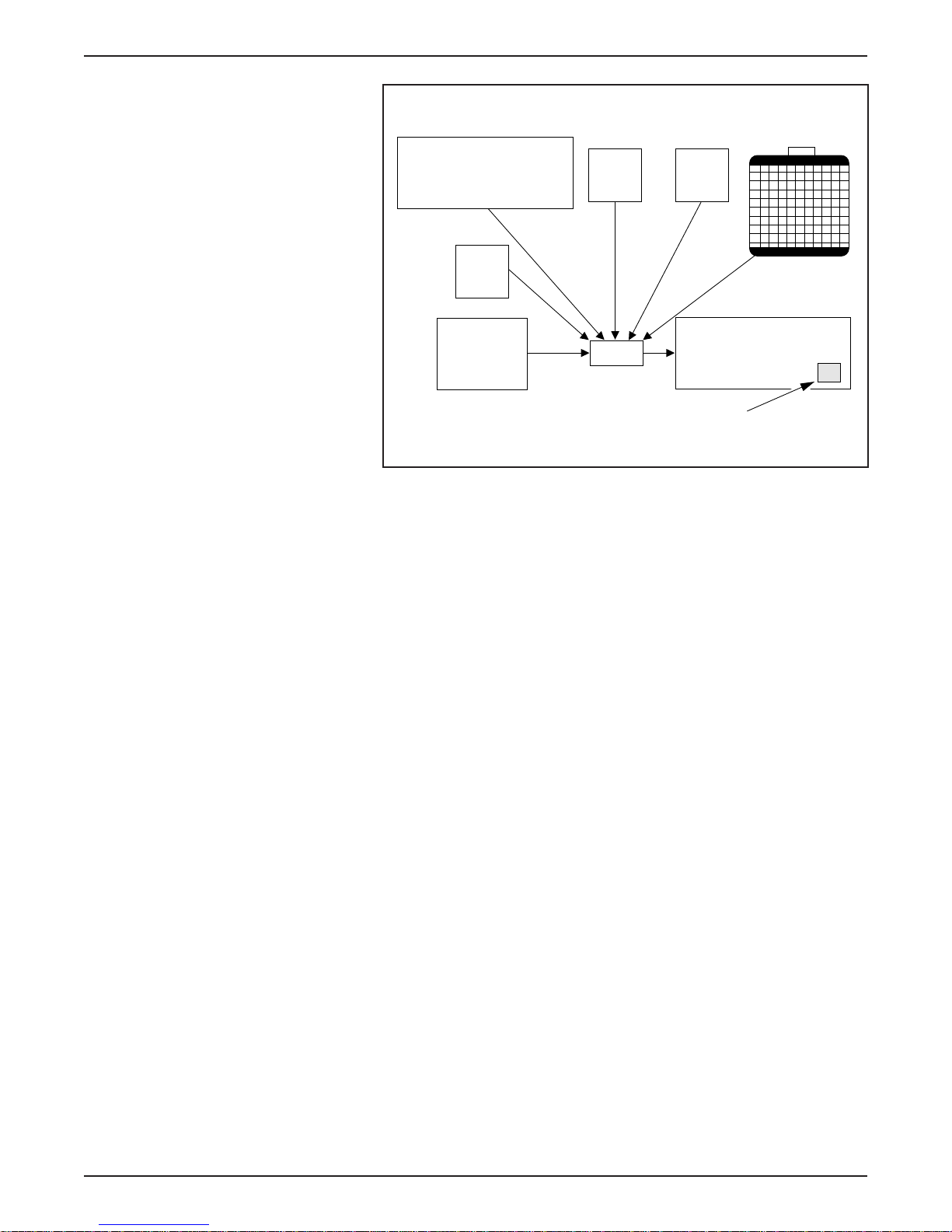
LESSON 2: VEHICLE OPERATION
TRACTION BATTERY
TIM
MOTOR/
TRANSAXLE
Temperature Gauge Inputs
DC/DC
CONVERTER
IAA
AC
INVERTER
INSTRUMENT CLUSTER
TEMPERATURE GAUGE
COOLANT
ER123-A
1998 Ranger EV New Model Training 2-13
Page 84
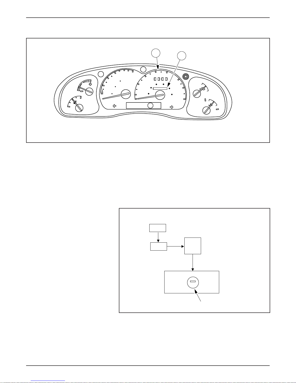
LESSON 2: VEHICLE OPERATION
Speedometer/Odometer/Tripmeter
ECON
MILES
F
E
Speedometer/Odometer/Tripmeter
A
40
0
6
100
4
0
DISTANCE
50
TO EMPTY
0
2
km
0
0
30
20
40
20
10
MPH
P RNDE
50
60 80
000000
B
60
100
70
120
80
km/h
ON
OFF
H
C
• The speedometer (A) is an electronically driven 0-130 km/h
(0-80 mph) gauge with a carryover Ranger odometer (B) and
tripmeter.
• The IAA monitors the ABS module for input from the rear
anti-lock brake system speed sensor. This input is used to indicate
vehicle speed.
ER057-A
REAR ABS
SPEED SENSOR
IAA
ABS
MODULE
SPEEDOMETER/ODOMETER
Speedometer/Odometer/Tripmeter Inputs
INSTRUMENT
CLUSTER
ER136-A
2-14 1998 Ranger EV New Model Training
Page 85
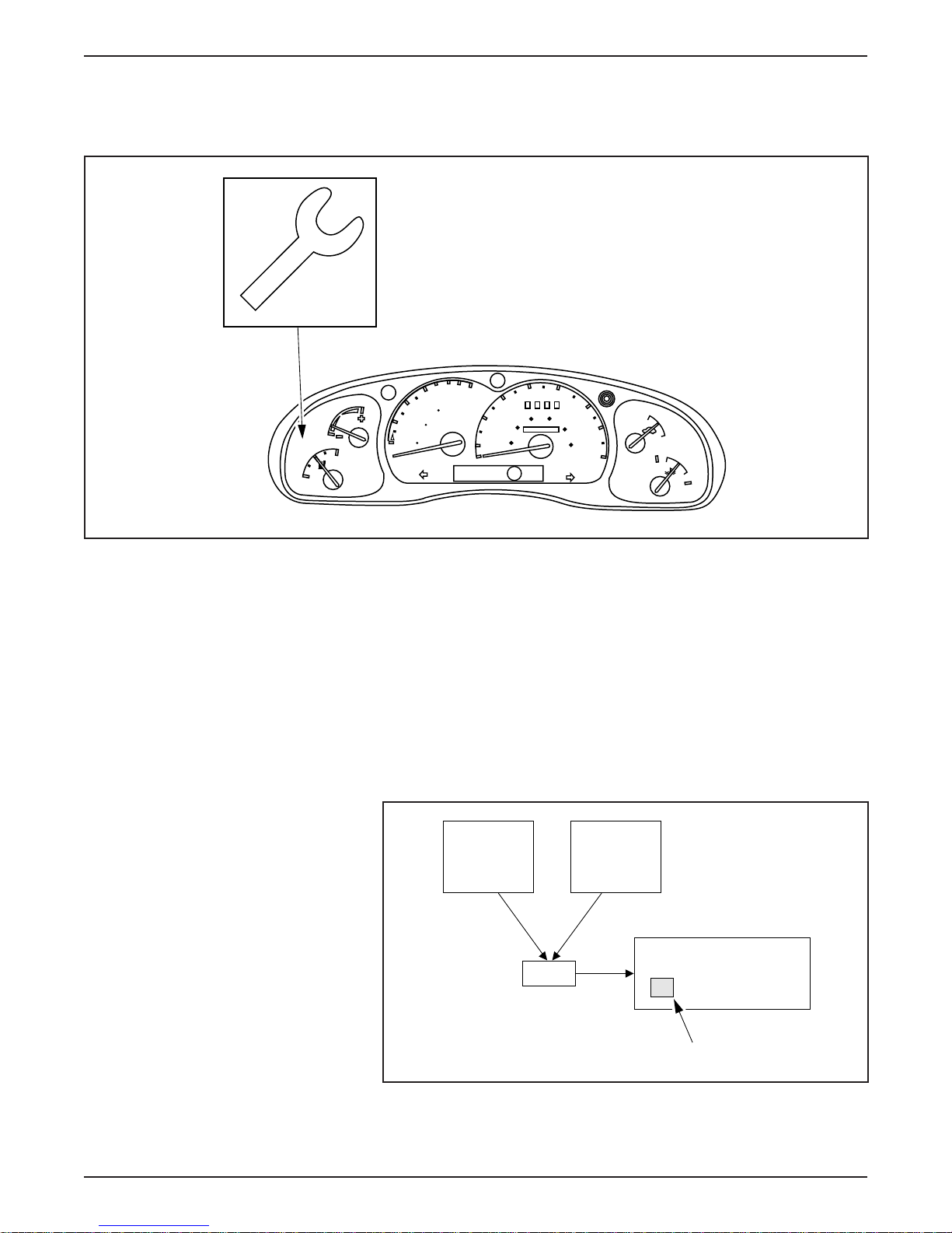
INSTRUMENT CLUSTER WARNING LAMPS
Malfunction Indicator Lamp (MIL)
0
6
100
4
0
MILES
DISTANCE
50
TO EMPTY
0
2
km
0
0
ECON
F
E
LESSON 2: VEHICLE OPERATION
30
20
40
000000
20
10
MPH
P RNDE
40
60 80
50
60
100
70
120
80
km/h
ON
OFF
H
C
Malfunction Indicator Lamp (MIL)
ER058-A
• The yellow MIL indicates a vehicle malfunction that requires
service.
• The MIL will illuminate during these conditions:
– a concern exists where long-term damage may result
– when a less serious concern occurs twice within five key cycles
• The IAA monitors the other “smart” modules and uses the MIL to
indicate a concern.
BCM TIM
INSTRUMENT CLUSTER
IAA
1998 Ranger EV New Model Training 2-15
MIL
ER124-A
MIL Inputs
Page 86
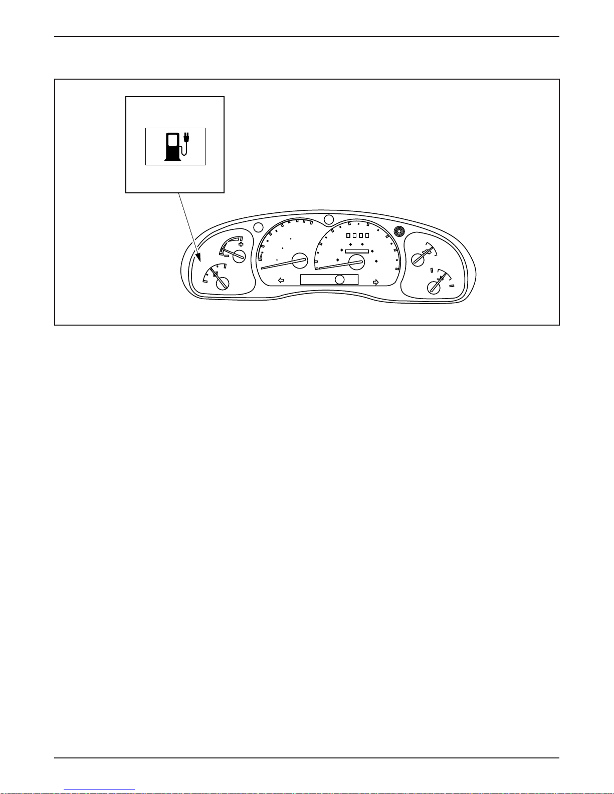
LESSON 2: VEHICLE OPERATION
Low Fuel Warning Lamp
ECON
F
E
MILES
2
0
40
0
6
100
4
0
DISTANCE
50
TO EMPTY
0
km
0
20
20
10
MPH
P RNDE
30
40
60 80
000000
50
60
100
70
120
80
km/h
ON
OFF
H
C
ER135-A
Low Fuel Warning Lamp
• The Low Fuel Warning Lamp alerts the driver when the state of
charge is low.
• This lamp illuminates when the traction battery state of charge
reaches 10%.
– Limited operating strategy is in effect when the lamp is
illuminated to conserve remaining power.
• The Low Fuel Warning Lamp will flash when the battery state of
charge reaches 0% (the vehicle has very limited range at this point).
– Speed is limited to 10 km/h (6 mph).
2-16 1998 Ranger EV New Model Training
Page 87
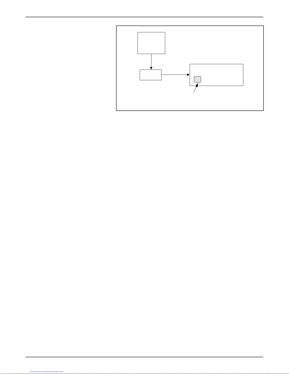
LESSON 2: VEHICLE OPERATION
BCM
INSTRUMENT CLUSTER
IAA
LOW FUEL
WARNING LAMP
ER125-A
Low Fuel Warning Lamp Inputs
NOTE: When this lamp flashes, range is very limited and the vehicle
should be returned to the repair facility. The Low Fuel Warning Lamp
will also illuminate or flash if a fault occurs in the system.
1998 Ranger EV New Model Training 2-17
Page 88
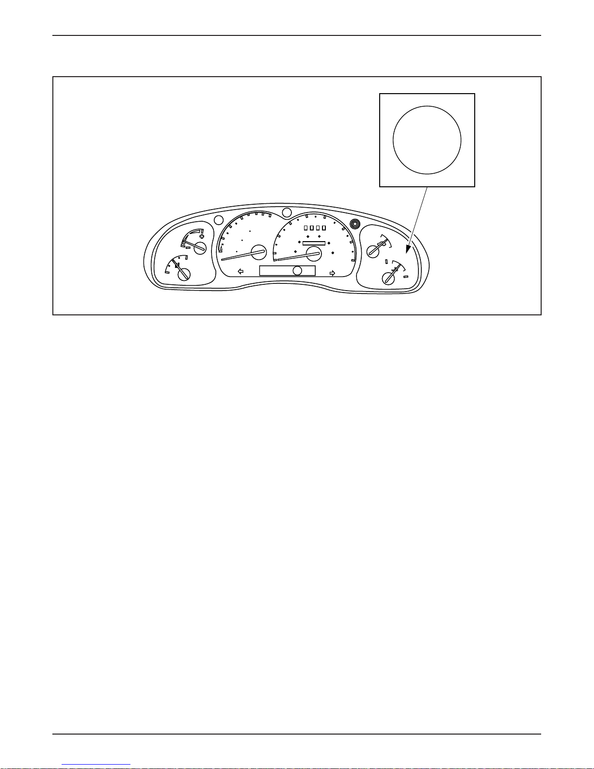
LESSON 2: VEHICLE OPERATION
POWER LIMIT Warning Lamp
0
6
100
4
0
MILES
DISTANCE
50
TO EMPTY
0
2
km
0
0
ECON
F
E
40
30
60 80
20
40
000000
20
10
MPH
P RNDE
POWER
LIMIT
50
60
100
70
120
80
km/h
ON
OFF
H
C
ER059-A
POWER LIMIT Warning Lamp
• The IAA monitors input from the TIM through the J1850 (SCP)
network and uses the POWER LIMIT Warning Lamp to indicate
the vehicle’s performance is limited to conserve remaining battery
power (lamp illuminated).
• As the traction battery nears complete discharge, the lamp begins to
flash to indicate performance is further limited to allow for safe
parking of the vehicle before the battery is completely drained.
2-18 1998 Ranger EV New Model Training
Page 89
LESSON 2: VEHICLE OPERATION
TIM
INSTRUMENT CLUSTER
IAA
POWER LIMIT Warning Lamp Inputs
POWER LIMIT
LAMP
ER126-A
1998 Ranger EV New Model Training 2-19
Page 90
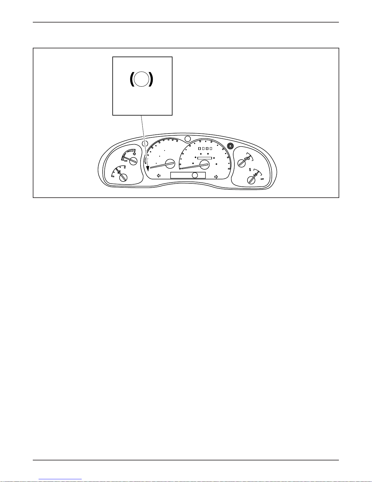
LESSON 2: VEHICLE OPERATION
BRAKE Warning Lamp
!
BRAKE
0
6
100
4
MILES
0
50
0
2
km
0
0
ECON
F
E
DISTANCE
TO EMPTY
P RNDE
40
40
60 80
000000
50
60
100
70
120
80
km/h
ON
OFF
H
C
30
20
20
10
MPH
ER060-A
BRAKE Warning Lamp
• The red BRAKE Warning Lamp will illuminate during the
following conditions:
– parking brake engaged.
– low brake fluid level in the master cylinder.
– regenerative braking system (RBS) malfunction.
– anti-lock brake system (ABS) malfunction.
• The IAA monitors several inputs and illuminates the red
BRAKE Warning Lamp if the parking brake is engaged,
there is a RBS failure, or there is a brake system concern.
2-20 1998 Ranger EV New Model Training
Page 91
LESSON 2: VEHICLE OPERATION
PARKING BRAKE
ABS
MODULE
MASTER CYLINDER
PRESSURE SENSOR
(LINE PRESSURE)
RED BRAKE
WARNING LAMP
BRAKE Warning Lamp Inputs
TIM (RBS)
IAA
INSTRUMENT CLUSTER
MASTER CYLINDER
(FLUID LEVEL)
NOTE: If the lamp illuminates, be sure the parking brake is not
engaged and the brake fluid level is correct before attempting
further diagnosis.
ER127-A
1998 Ranger EV New Model Training 2-21
Page 92
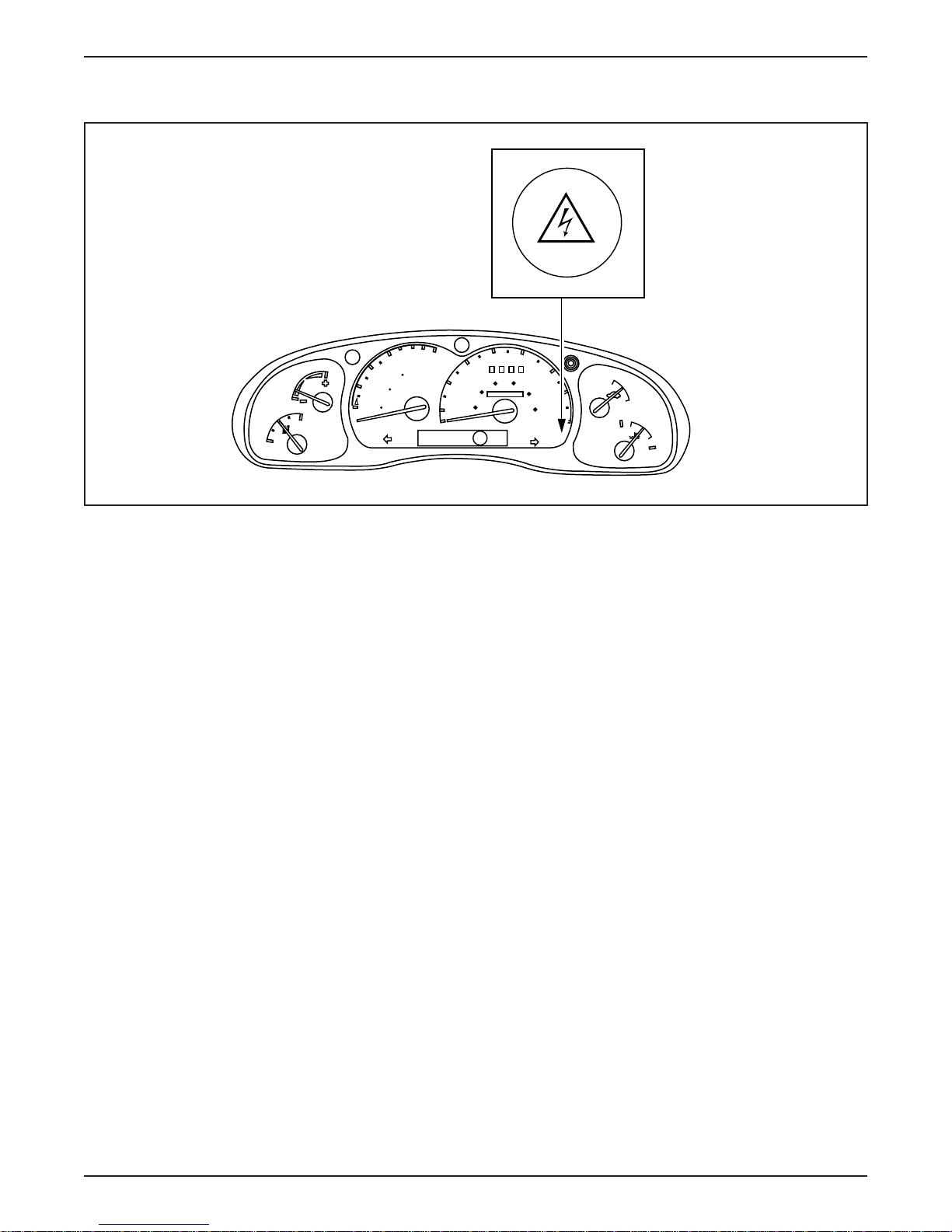
LESSON 2: VEHICLE OPERATION
Electric Hazard Warning Lamp
0
6
100
4
0
ECON
F
E
MILES
DISTANCE
50
TO EMPTY
0
2
km
0
0
40
30
60 80
20
40
000000
20
10
MPH
P RNDE
50
60
100
70
120
80
km/h
ON
OFF
H
C
ER061-A
Electric Hazard Warning Lamp
• The red Electric Hazard Warning Lamp will illuminate during the
following conditions:
– severe current leakage is detected.
– a high voltage interlock is opened.
• If current leakage is detected, the vehicle will continue to operate.
• To prevent possible damage to the vehicle or personal injury, the
vehicle must be repaired immediately.
• If a high voltage interlock is opened, the emergency power off
(EPO) system will cause all high voltage to be disabled and shut
down the vehicle (for more information on EPO see Lesson 1).
• The BCM monitors for current leakage. If current leakage is
present or a high voltage interlock is open the BCM will signal the
IAA to illuminate the Electric Hazard Warning Lamp.
2-22 1998 Ranger EV New Model Training
Page 93

LESSON 2: VEHICLE OPERATION
INSTRUMENT CLUSTER
BCM
IAA
ELECTRIC HAZARD
WARNING LAMP
ER128-A
Electric Hazard Warning Lamp Inputs
NOTE: If an electrical hazard is present, the electric hazard warning
lamp only illuminates with the key in the START or ON position.
1998 Ranger EV New Model Training 2-23
Page 94
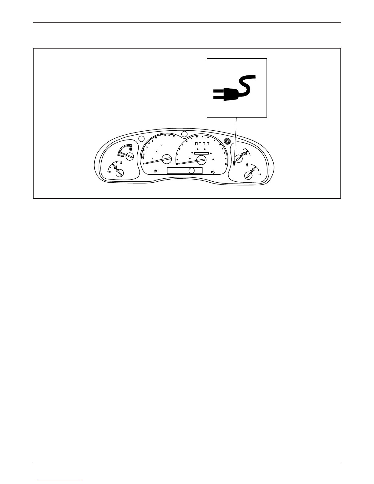
LESSON 2: VEHICLE OPERATION
Charging Indicator Lamp
0
6
100
4
0
ECON
F
E
MILES
DISTANCE
50
TO EMPTY
0
2
km
0
0
40
30
60 80
20
40
000000
20
10
MPH
P RNDE
50
60
100
70
120
80
km/h
ON
OFF
H
C
ER062-A
Charging Indicator Lamp
• The red Charging Indicator Lamp will illuminate during charging
if the key is turned to the START or ON position.
• The vehicle cannot be “started” and should not be moved while the
charging cord is plugged into the charge inlet.
• The IAA monitors several inputs to indicate if it is safe to charge
the traction battery.
• If the driver attempted to start the vehicle with the charger
connected the lamp will illuminate to indicate it is not possible to
operate the vehicle with the charger connected.
• The charging indicator lamp also indicates if it is not safe to charge
the battery pack.
– The lamp will flash if a charging fault exists.
2-24 1998 Ranger EV New Model Training
Page 95
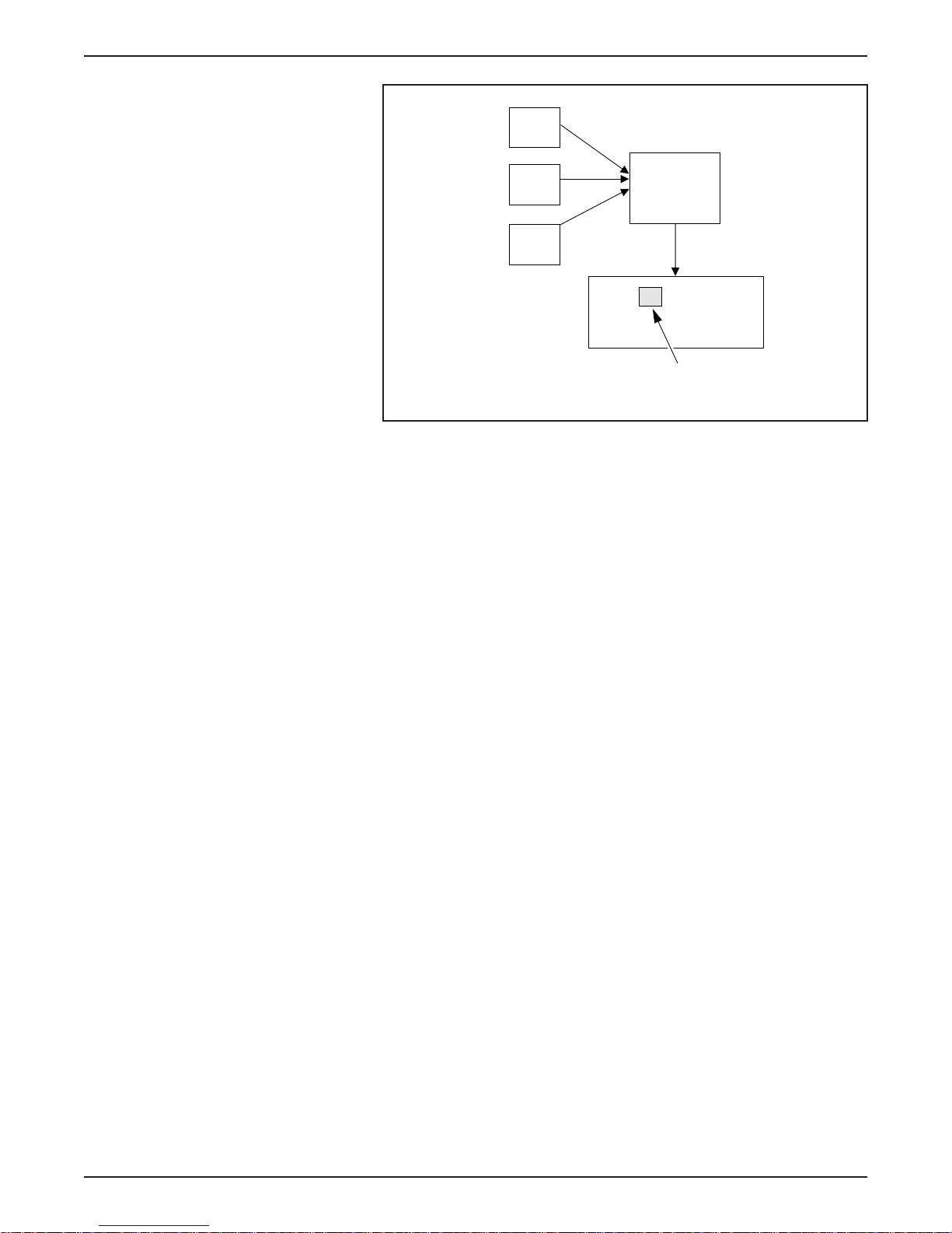
LESSON 2: VEHICLE OPERATION
CHARGE INLET
DTR SWITCH
IAA
IGNITION
SWITCH
INSTRUMENT
CLUSTER
CHARGING
INDICATOR LAMP
ER129-A
Charging Indicator Lamp Inputs
NOTE: The Charging Indicator Lamp will flash when the key is in
the ON position and it is unsafe to charge (vehicle not in PARK [P]),
severe current leakage, open interlock or activated inertia
shutoff switch).
1998 Ranger EV New Model Training 2-25
Page 96
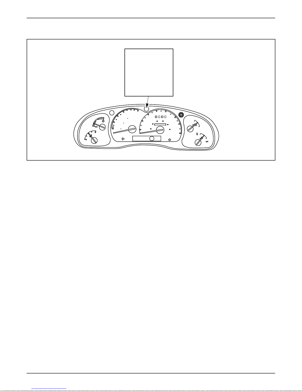
LESSON 2: VEHICLE OPERATION
POWER RESET Indicator Lamp
0
6
100
4
0
ECON
F
E
MILES
DISTANCE
50
TO EMPTY
0
2
km
0
0
POWER
RESET
40
30
60 80
20
40
000000
20
10
MPH
P RNDE
50
60
100
70
120
80
km/h
ON
OFF
H
C
ER063-A
POWER RESET Indicator Lamp
• The yellow POWER RESET Indicator Lamp will illuminate when
the inertia shutoff switch has been activated.
• When activated the inertia shutoff switch disables all high voltage
power to the vehicle electrical system.
• If no special service is required, pressing the reset button on top of
the inertia shutoff switch can restore power to the high voltage
circuits.
• The IAA monitors the inertia shutoff switch. If the switch is
activated, high voltage circuits are interrupted and the POWER
RESET Indicator Lamp is illuminated.
• The IAA opens the negative contactor relay and signals the BCM to
command the TIM to open the positive contactor relay.
• The IAA uses the J1850 (SCP) network to communicate these
commands to the other control modules.
2-26 1998 Ranger EV New Model Training
Page 97
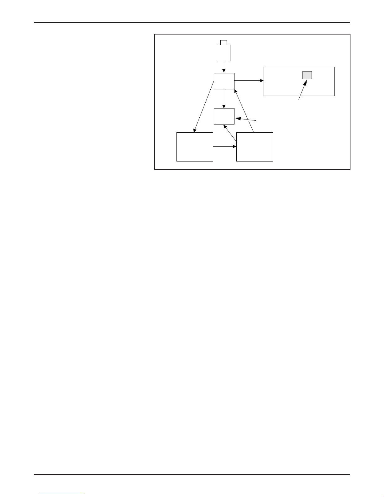
LESSON 2: VEHICLE OPERATION
INERTIA SHUTOFF
SWITCH
INSTRUMENT CLUSTER
IAA
POWER RESET
INDICATOR LAMP
CONTACTOR
BOX
BCM TIM
POWER RESET Indicator Lamp Inputs
NOTE: The inertia shutoff switch is located in the passenger
compartment, above the carpet line and below the evaporator
assembly.
ER130-A
1998 Ranger EV New Model Training 2-27
Page 98
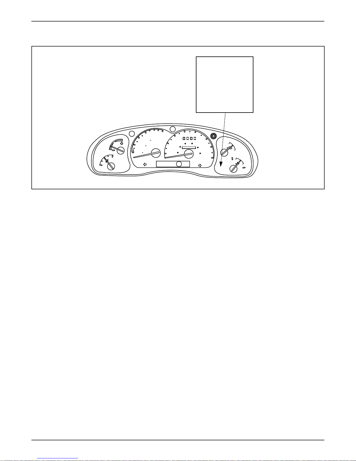
LESSON 2: VEHICLE OPERATION
ECON MODE Indicator Lamp
0
6
100
4
0
ECON
F
E
MILES
DISTANCE
50
TO EMPTY
0
2
km
0
0
40
30
60 80
20
40
000000
20
10
MPH
P RNDE
50
100
km/h
ECON
MODE
60
70
120
80
ON
OFF
H
C
ER064-A
ECON MODE Indicator Lamp
• The green ECON MODE Indicator Lamp will illuminate when the
driver has selected the economy driving mode (E).
• The economy mode will increase the level of regenerative braking
to improve vehicle range.
• The brightness of this lamp is controlled by the instrument cluster
lamp dimmer control.
• The TIM monitors the DTR sensor and relays information to
the IAA.
• When the driver selects economy mode, the TIM informs the IAA
and the IAA illuminates the ECON MODE Indicator Lamp.
2-28 1998 Ranger EV New Model Training
Page 99
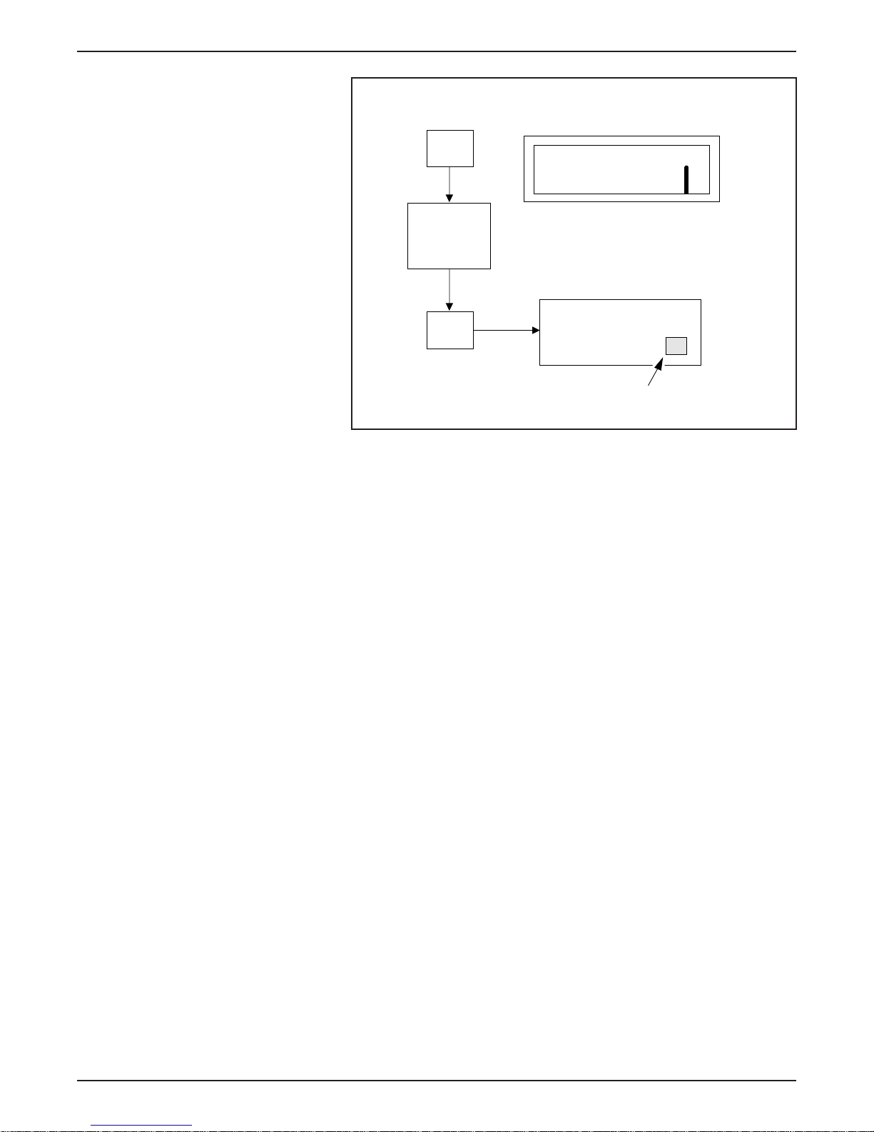
LESSON 2: VEHICLE OPERATION
DTR
P R N D E
TIM
INSTRUMENT CLUSTER
IAA
ECON MODE
INDICATOR LAMP
ECON MODE Indicator Lamp Inputs
ER132-A
1998 Ranger EV New Model Training 2-29
Page 100
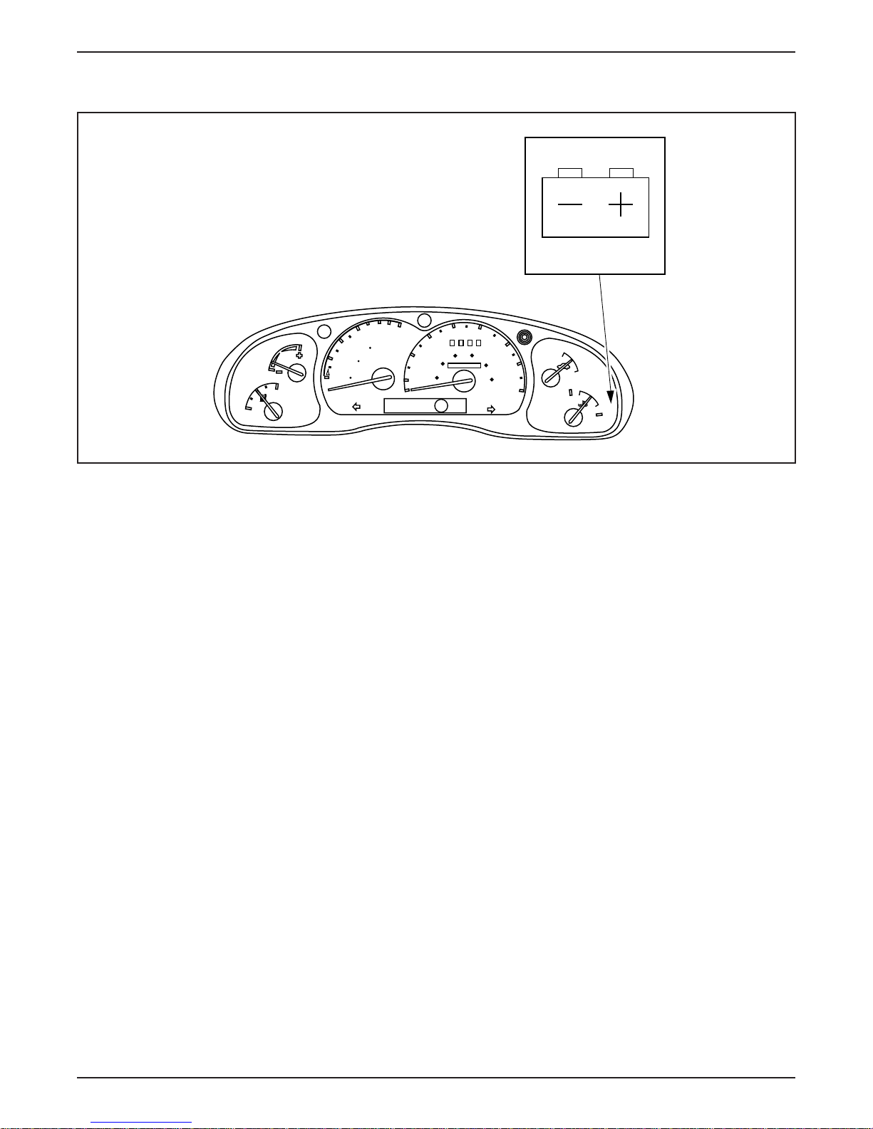
LESSON 2: VEHICLE OPERATION
Auxiliary Battery Warning Lamp
0
6
100
4
0
MILES
DISTANCE
50
TO EMPTY
0
2
km
0
0
ECON
F
E
40
30
60 80
20
40
000000
20
10
MPH
P RNDE
50
60
100
70
120
80
km/h
ON
OFF
H
C
ER065-A
Auxiliary Battery Warning Lamp
• The red Auxiliary Battery Warning Lamp will illuminate during the
following conditions:
– the auxiliary battery voltage exceeds 15.75 volts.
– the auxiliary battery voltage falls below 11.5 volts.
• If the auxiliary battery voltage warning lamp illuminates, the driver
must pull over to a safe area and have the vehicle repaired.
• The IAA monitors the auxiliary battery voltage. If voltage exceeds
15.75 volts or falls below 11.5 volts the IAA illuminates the
Auxiliary Battery Warning Lamp.
2-30 1998 Ranger EV New Model Training
 Loading...