

Page 1

Factory Workshop Manual
Ford
E 250 Van
V8-6.9L DSL (1985)
Anonymous
1st January 2018
Make
Model
Engine and year
This manual was submitted by
Date
Page 2

Ford E 250 Van Workshop Manual (V8-6.9L DSL (1985))
Ford Workshop Manuals > A L L Diagnostic Trouble Codes ( DTC ) > Codes by System > A L L Diagnostic Trouble Codes Engine Controls > System Information > System Diagnosis > Transmisson Codes
Page 3

A L L Diagnostic Trouble Codes - Engine Controls: Testing and Inspection Transmisson Codes
For Transmission related codes, proceed to Computers and Control Systems.
Page 4

Ford E 250 Van Workshop Manual (V8-6.9L DSL (1985))
Ford Workshop Manuals > A L L Diagnostic Trouble Codes ( DTC ) > Codes by System > A L L Diagnostic Trouble Codes Trans and Drivetrain > System Information > System Diagnosis
Page 5

A L L Diagnostic Trouble Codes - Trans and Drivetrain: Testing and Inspection
For Transmission related codes, proceed to Computers and Control Systems.
Page 6

Ford E 250 Van Workshop Manual (V8-6.9L DSL (1985))
Ford Workshop Manuals > Relays and Modules > Relays and Modules - Body and Frame > Power Door Lock Relay >
Component Information > Locations
Page 7

Power Door Lock Relay: Locations
Lower LH Cowl Near Fuse Panel
Page 8

Ford E 250 Van Workshop Manual (V8-6.9L DSL (1985))
Ford Workshop Manuals > Relays and Modules > Relays and Modules - Cruise Control > Cruise Control Module >
Component Information > Locations
Page 9

Cruise Control Module: Locations
LH Side Of I/P
Page 10

Ford E 250 Van Workshop Manual (V8-6.9L DSL (1985))
Ford Workshop Manuals > Relays and Modules > Relays and Modules - Cruise Control > Cruise Control Module >
Component Information > Locations > Page 20
Page 11

Cruise Control Module: Testing and Inspection
Use only a multi-meter of 5000 ohm/volt rating or higher when performing amplifier test.
``On'' Circuit Test
1. Turn ignition ``On.''
2. Connect a voltmeter between light blue wire w/black hash and ground on models exc. 1983-87
Ranger, 1984-87 Bronco II and 1986-87 Aerostar or white wire w/purple stripe and ground on
1983-87 Ranger, 1984-87 Bronco II and 1986-87 Aerostar.
3. Battery voltage should be indicated when ``On'' switch on steering column is depressed and
held. If battery voltage is not indicated, check horn relay and perform control switch test.
4. Release ``On'' button. Voltmeter should indicate 7.8 volts indicating ``On'' circuit is engaged. If
voltage does not remain, check amplifier ground, fuses or circuit breakers or replace amplifier with
known good amplifier and repeat test.
5. Replace as necessary.
``Off'' Circuit Test
1. Turn ignition ``On.''
2. Connect a voltmeter between light blue wire w/black hash and ground.
3. Depress ``Off'' button. Voltage should drop to zero indicating ``On'' circuit is de-energized.
4. If voltage does not drop to zero, perform ``Control Switch Test.''
``Set-Accelerate'' Circuit Test
1. Turn ignition ``On.''
2. Connect a voltmeter between light blue wire w/black hash and ground.
3. Depress ``On'' switch, then hold ``Set-Accel'' button on steering wheel. Voltmeter should indicate
4.5 volts. Rotate steering wheel back and forth and check for voltmeter fluctuations. If reading
varies more than .5 volts, perform ``Control Switch Test.''
``Coast'' Circuit Test
1. Turn ignition ``On.''
2. Connect a voltmeter between light blue wire w/black hash and ground.
3. Depress ``On'' switch, then depress and hold ``Coast'' button on steering wheel. Voltmeter
should indicate 1.5 volts. Rotate steering wheel back and forth and check for voltage fluctuations. If
reading varies more than .5 volts, perform ``Control Switch Test.''
``Resume'' Circuit Test
1. Turn ignition ``On.''
2. Connect a voltmeter between light blue wire w/black hash and ground.
3. Depress and hold ``Resume'' button. Voltmeter should indicate 6.5 volts.
If all circuits are functioning properly, perform ``Servo Assembly
Page 12

Test'' using a known good amplifier. Do not replace amplifier before performing servo test.
Page 13
Ford E 250 Van Workshop Manual (V8-6.9L DSL (1985))
Ford Workshop Manuals > Relays and Modules > Relays and Modules - HVAC > Blower Motor Relay > Component
Information > Locations
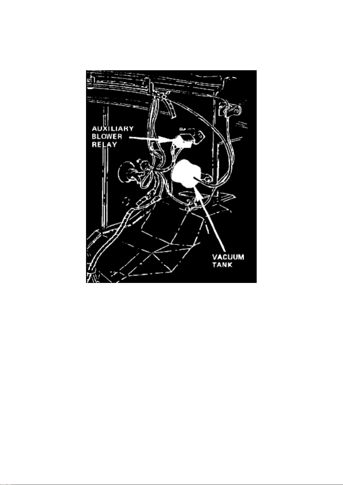
Blower Motor Relay: Locations
LH Side Of Dash
LH Corner Of Engine Compartment
Page 14
Ford E 250 Van Workshop Manual (V8-6.9L DSL (1985))
Ford Workshop Manuals > Relays and Modules > Relays and Modules - Lighting and Horns > Headlamp Control Module >
Component Information > Diagrams > Diagram Information and Instructions
Page 15

Headlamp Control Module: Diagram Information and Instructions
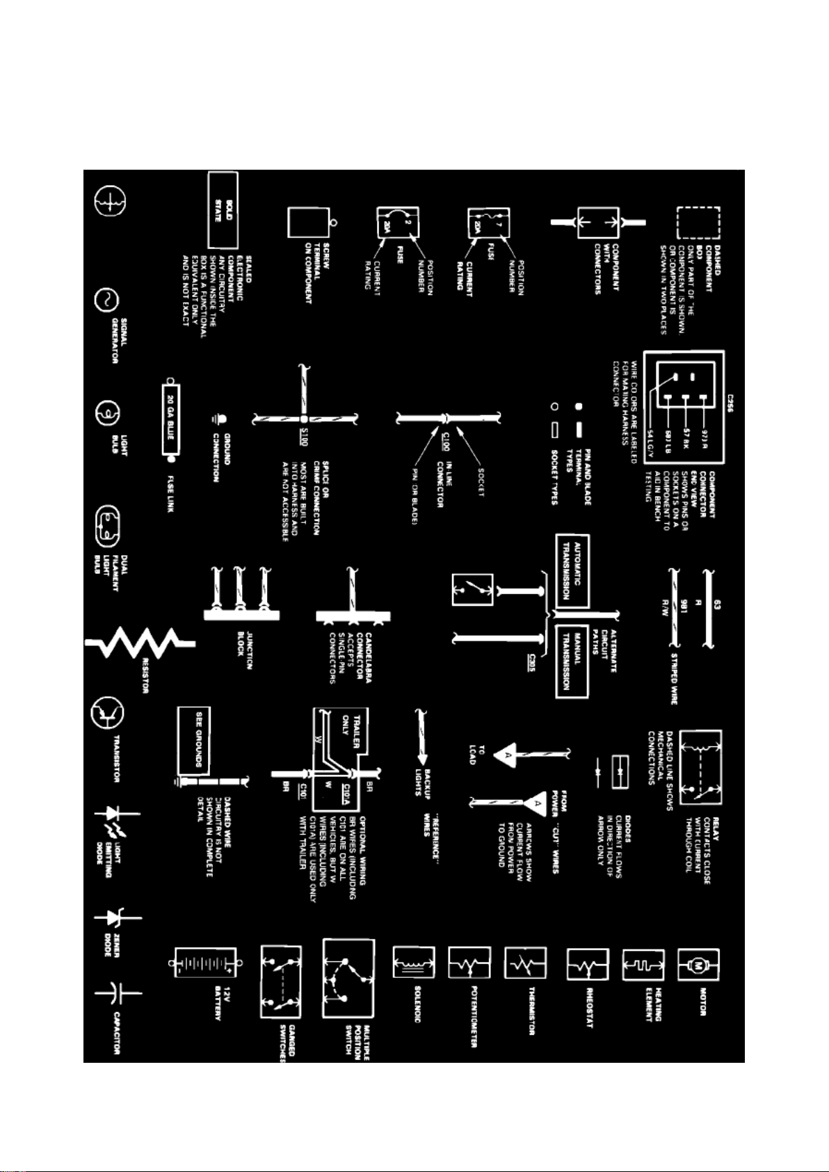
Symbol Identification
Wire Color Code Identification
Page 16

Ford E 250 Van Workshop Manual (V8-6.9L DSL (1985))
Ford Workshop Manuals > Relays and Modules > Relays and Modules - Lighting and Horns > Headlamp Control Module >
Component Information > Diagrams > Diagram Information and Instructions > Page 30
Page 17

NOTE: Whenever a wire is labeled with two colors; the first color listed is the basic color of the
wire, and the second color is the tracer marking of the wire. If the second color is followed by by a
D, the tracer is dots. If the second color is followed by an H, the tracer is hash marks.
For example: BR/O is a brown wire with an orange stripe, R/Y D is a red wire with yellow dots and
BK/W H is a black wire with white hash marks.
BL: Blue BK: Black BR: Brown DB: Dark Blue DG: Dark Green GR: Green GY: Gray LB: Light Blue
LG: Light Green N:
Natural
O: Orange
PK: Pink R:
Red
P: Purple
T: Tan
V: Violet
W: White
Y: Yellow
Page 18
Ford E 250 Van Workshop Manual (V8-6.9L DSL (1985))
Ford Workshop Manuals > Relays and Modules > Relays and Modules - Lighting and Horns > Headlamp Control Module >
Component Information > Diagrams > Diagram Information and Instructions > Page 31
Page 19

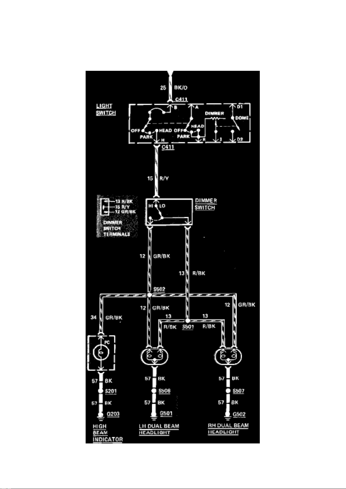
Fig. 30 Headlamp Wiring Circuit. 1985
Page 20
Ford E 250 Van Workshop Manual (V8-6.9L DSL (1985))
Ford Workshop Manuals > Relays and Modules > Relays and Modules - Lighting and Horns > Horn Relay > Component
Information > Locations
Page 21

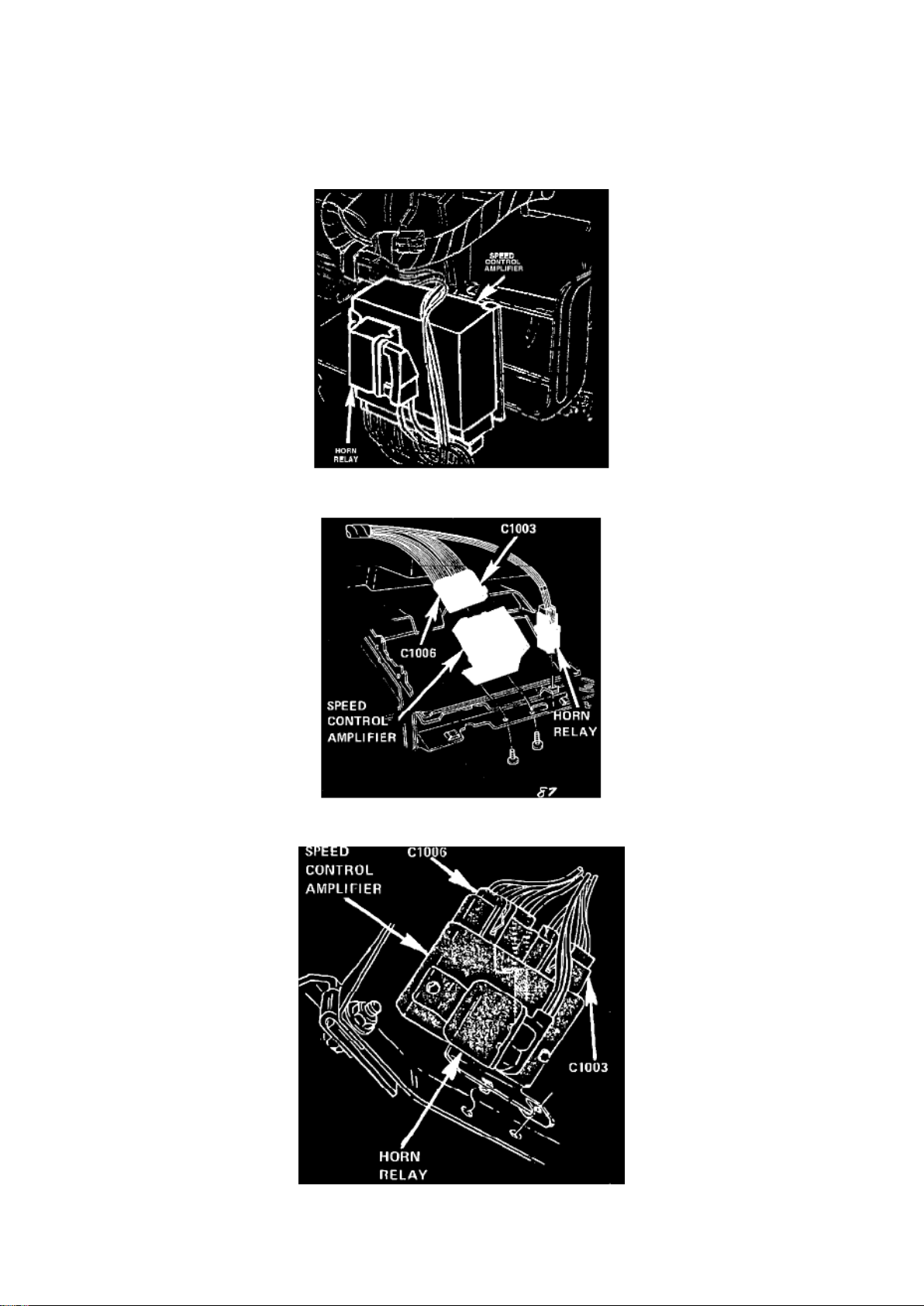
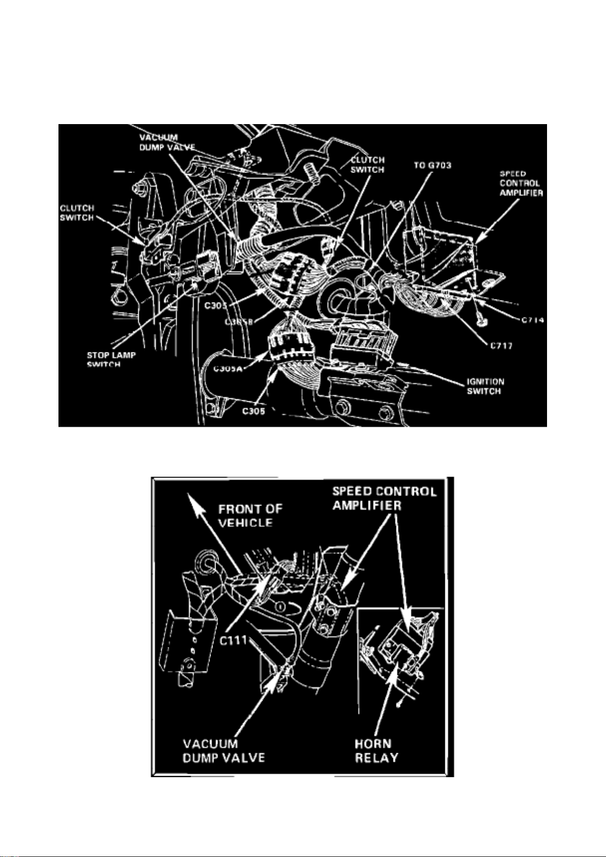
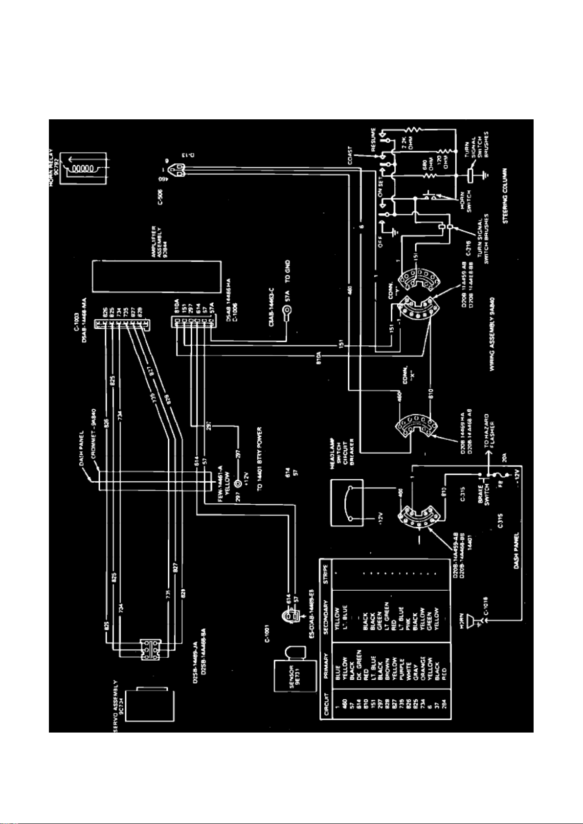
Horn Relay: Locations
Horn Relay Location
Under LH Side Of I/P.
Under LH Side Of I/P, With Speed Control
Page 22
Ford E 250 Van Workshop Manual (V8-6.9L DSL (1985))
Ford Workshop Manuals > Relays and Modules > Relays and Modules - Lighting and Horns > Horn Relay > Component
Information > Locations > Page 35
Page 23

Underneath LH Side Of I/P
Below LH Side Of I/P
Horn Relay With Speed Control
Bronco F-150 thru F-350, E-150 thru E-350 and Super F Series The horn relay is use on vehicles
equipped with speed control and is located under the left side of the instrument panel, left of the
steering column and is mounted on the outboard attaching screw of the speed control amplifier
module.
Page 24
Ford E 250 Van Workshop Manual (V8-6.9L DSL (1985))
Ford Workshop Manuals > Relays and Modules > Relays and Modules - Lighting and Horns > Horn Relay > Component
Information > Locations > Page 36
Page 25

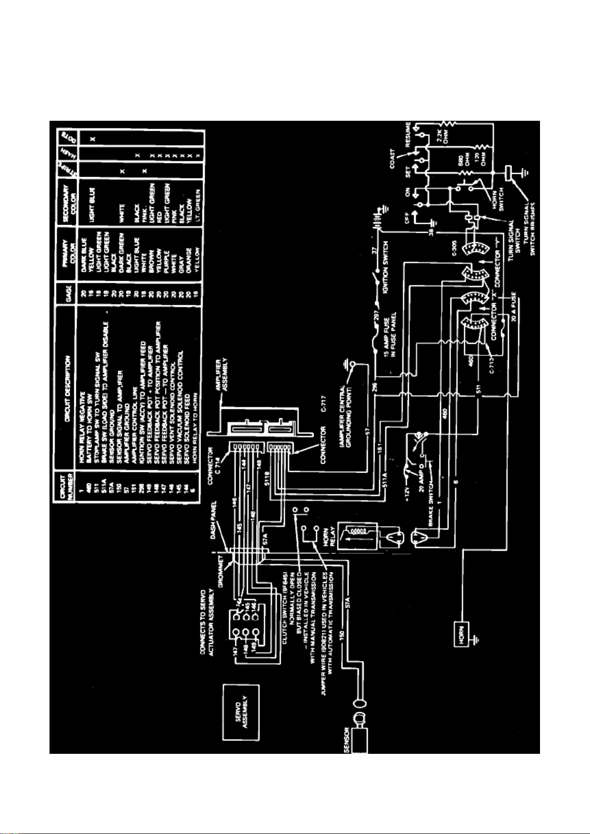
Horn Relay: Testing and Inspection
Fig. 3 Speed control wiring diagram. 1981---83 E-100-350 & 1984-87 E-150-350
Page 26
Ford E 250 Van Workshop Manual (V8-6.9L DSL (1985))
Ford Workshop Manuals > Relays and Modules > Relays and Modules - Lighting and Horns > Horn Relay > Component
Information > Locations > Page 37
Page 27

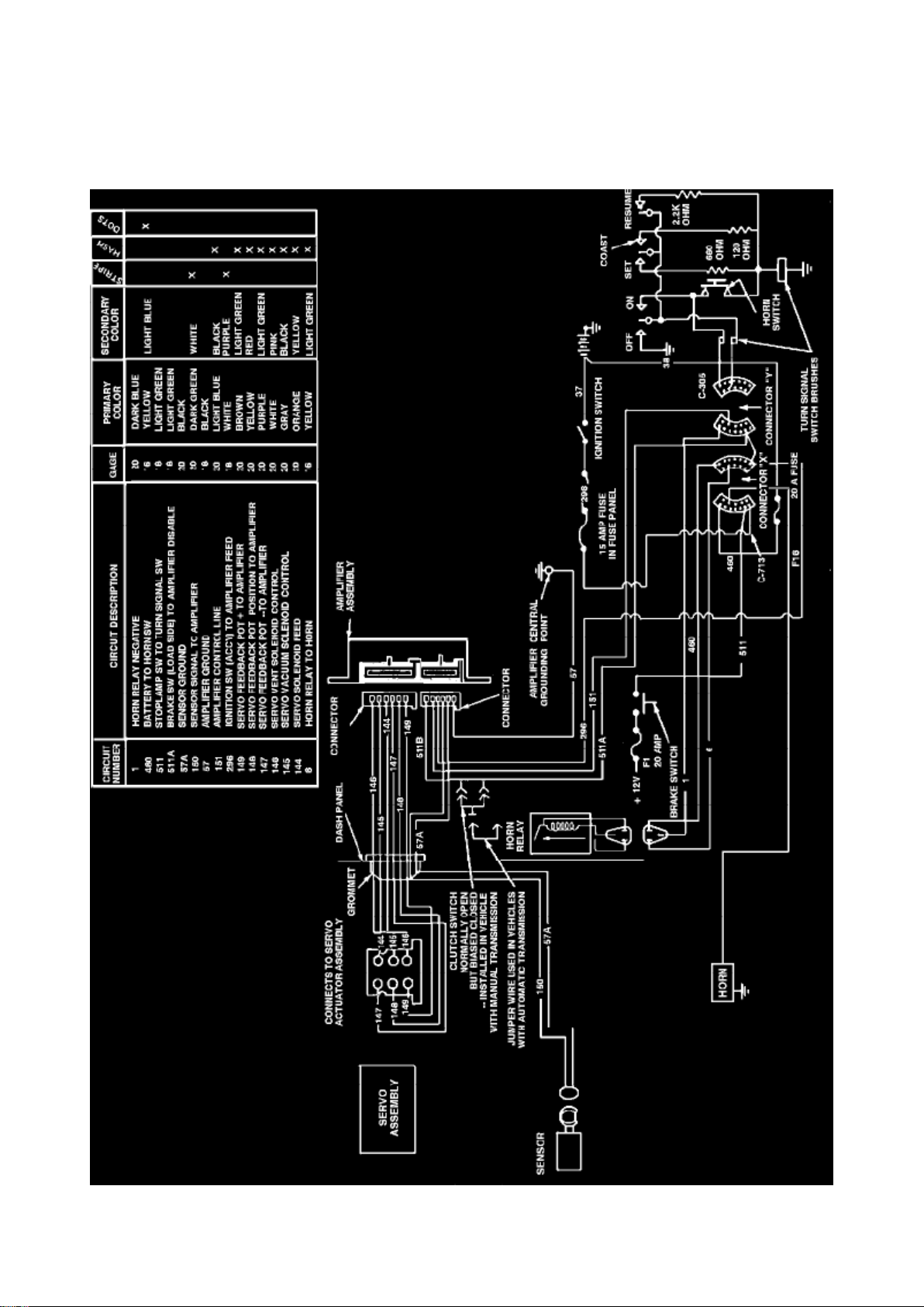
Fig. 4 Speed control wiring diagram. 1981 F-100-350 & Bronco
Page 28
Ford E 250 Van Workshop Manual (V8-6.9L DSL (1985))
Ford Workshop Manuals > Relays and Modules > Relays and Modules - Lighting and Horns > Horn Relay > Component
Information > Locations > Page 38
Page 29

Fig. 5 Speed control wiring diagram. 1982---83 F-100-350, 1984---87 F-150-350 & 1982---87
Bronco
1981-87 Models Exc. 1983-87 Ranger, 1984-87 Bronco II & 1986-87 Aerostar
1. Locate horn relay wire connector marked X and Y, Figs. 3, 4 and 5.
2. Using connector X, locate wire 460, then using a suitable voltmeter, check for battery voltage at
male side of connector.
3. Using connector Y, locate wire 1, then using a suitable voltmeter, check for battery voltage at
female side of connector. Depress horn, voltmeter should read zero and horn should sound. If
battery voltage remains, circuit is open. Connectors should remain connected during testing.
4. Check horn relay by momentarily grounding circuit 1 to chassis. This bypasses horn switch and
horn should sound. If horn does not sound, check for battery voltage at connector X wire 6 during
relay operation. If voltage is present at circuit 6 during relay operation, an open circuit is indicated
between horn and connector X.
5. If relay does not operate with battery voltage present at circuit 460 and circuit 1 is grounded,
replace relay.
Page 30

Ford E 250 Van Workshop Manual (V8-6.9L DSL (1985))
Ford Workshop Manuals > Relays and Modules > Relays and Modules - Lighting and Horns > Trailer Lighting Relay >
Component Information > Locations
Page 31

Trailer Lighting Relay: Locations
LH Rear Fender Below LH Taillight
Page 32

Ford E 250 Van Workshop Manual (V8-6.9L DSL (1985))
Ford Workshop Manuals > Relays and Modules > Relays and Modules - Power and Ground Distribution > Power Protection
Relay > Component Information > Locations
Page 33

Power Protection Relay: Locations
In Engine Compartment On LH Fender Apron
Page 34

Ford E 250 Van Workshop Manual (V8-6.9L DSL (1985))
Ford Workshop Manuals > Relays and Modules > Relays and Modules - Powertrain Management > Relays and Modules Computers and Control Systems > Engine Control Module > Component Information > Technical Service Bulletins >
Body/Frame - Arc Welding Precautions
Page 35

Engine Control Module: Technical Service Bulletins Body/Frame - Arc Welding Precautions
Page 36

Article No. 90-11-6
EEC IV-ELECTRONIC CONTROL MODULES AND PROCESSORS-POSSIBLE DAMAGE FROM
ARC WELDING
FORD: 1985-90 CROWN VICTORIA, ESCORT, MUSTANG, TEMPO, THUNDERBIRD 1986-90
TAURUS
LINCOLN-MERCURY: 1985-86 CAPRI
1985-90 CONTINENTAL, COUGAR, GRAND MARQUIS, MARK VII, TOPAZ, TOWN CAR 1986-90
SABLE
MERKUR: 1985-89 XR4Ti 1988-90 SCORPIO
LIGHT TRUCK: 1985-90 BRONCO II, BRONCO, ECONOLINE, F-150, F-250, F-350, RANGER
1986-90 AEROSTAR 1989-90 F SUPER DUTY 1991 EXPLORER
ISSUE: Electronic control modules, including EEC processors, may be damaged if the negative
battery ground cable is not disconnected before arc welding is done to the vehicle, This occurs
because the arc welding process can produce high electrical currents in the body of a vehicle when
the negative battery ground cable is left connected.
ACTION: If arc welding procedures are to be performed, be sure to disconnect the battery ground
cable,
CAUTION: DISCONNECT THE NEGATIVE BATTERY GROUND CABLE BEFORE USING ANY
ELECTRIC WELDING EQUIPMENT
OTHER APPLICABLE ARTICLES: None WARRANTY STATUS: INFORMATION ONLY OASIS
CODES:
2800, 680000
Page 37
Ford E 250 Van Workshop Manual (V8-6.9L DSL (1985))
Ford Workshop Manuals > Relays and Modules > Relays and Modules - Powertrain Management > Relays and Modules Glow Plug System > Glow Plug Control Module > Component Information > Locations
Page 38

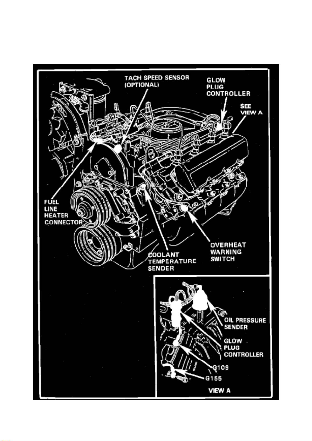
Glow Plug Control Module: Locations
LH Side Of Engine.
Page 39
Ford E 250 Van Workshop Manual (V8-6.9L DSL (1985))
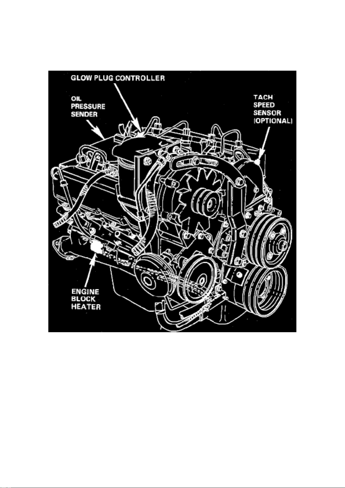
Ford Workshop Manuals > Relays and Modules > Relays and Modules - Powertrain Management > Relays and Modules Glow Plug System > Glow Plug Control Module > Component Information > Locations > Page 56
RH Side Of Engine.
Page 40

Ford E 250 Van Workshop Manual (V8-6.9L DSL (1985))
Ford Workshop Manuals > Relays and Modules > Relays and Modules - Powertrain Management > Relays and Modules Glow Plug System > Glow Plug Relay > Component Information > Locations
Page 41

Glow Plug Relay: Locations
Upper LH Dash Panel
Page 42

Ford E 250 Van Workshop Manual (V8-6.9L DSL (1985))
Ford Workshop Manuals > Relays and Modules > Relays and Modules - Powertrain Management > Relays and Modules Ignition System > Ignition Control Module > Component Information > Technical Service Bulletins > Engine Compartment
Wiring - Connector Service
Page 43

Ignition Control Module: Technical Service Bulletins Engine Compartment Wiring - Connector
Service
Page 44

Article No. 85-17-3
WIRING - ENGINE COMPARTMENT SERVICING TERMINALS/CONNECTORS ON 12A581 AND 14290 ASSEMBLIES FOR
INTERMITTENT CONCERNS
FORD 1985 ALL
LINCOLN-MERCURY 1985 ALL
LIGHT TRUCK 1985 ALL
When intermittent symptoms are reported and any of the components listed below are suspect,
then the following procedure should be performed before the start of normal diagnostics.
Component Connectors and Systems Affected:
^ TFI Ignition Module
^ Map Sensor
^ Air Vane Boost Control
^ Power Steering
^ ISC
^ Fuel Injector
^ Anti-Skid Pressure Switch
^ Anti-Skid Control Valve
^ Fluid Level Sensor
^ Main Hydraulic Valve
Terminal and Connector Inspection/Repair Procedure
1. Pull on each wire of the subject connector using approximately 3 to 5 lbs. force.
2. If the terminal pulls out of the connector, remove the terminal from wire and replace with a new
terminal.
3. Remove wedge from connector and install the new terminal and wire in the connector.
4. Replace the wedge and again pull on the wire. If the new terminal pulls out of connector, replace
connector.
A. Remove the wedge from connector and remove the remaining terminals, but leave the rubber
grommet on wires to aid in reinstalling the terminals in the correct position in the connector.
B. Reinstall all terminals into the new connector and reinstall the wedge.
C. Install the new connector making sure that it is fully seated to the mating connector (locking
fingers completely over ramp).
OTHER APPLICABLE ARTICLES: None WARRANTY STATUS: Reimbursable within the
provisions of the Warranty and Policy Manual. OPERATON:
Page 45

SP14290B85
TIME: 0.3 Hr. DLR. CODING: Basic Part No. 12A581 and/or 14290 - Code: 44
Page 46
Ford E 250 Van Workshop Manual (V8-6.9L DSL (1985))
Ford Workshop Manuals > Relays and Modules > Relays and Modules - Starting and Charging > Starter Relay >
Component Information > Locations
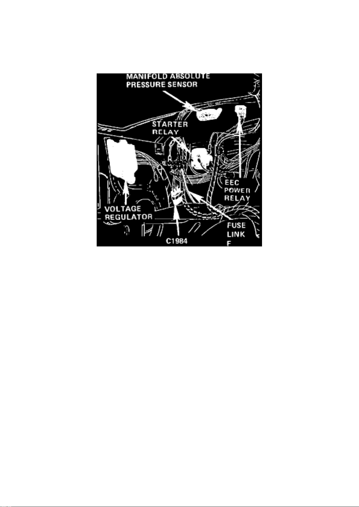
Starter Relay: Locations
RH Fender Apron w/EEC
On RH Fender Apron
Page 47

Ford E 250 Van Workshop Manual (V8-6.9L DSL (1985))
Ford Workshop Manuals > Relays and Modules > Relays and Modules - Windows and Glass > Power Window Relay >
Component Information > Locations
Page 48

Power Window Relay: Locations
Lower LH Cowl Near Fuse Panel
Page 49
Ford E 250 Van Workshop Manual (V8-6.9L DSL (1985))
Ford Workshop Manuals > Relays and Modules > Relays and Modules - Wiper and Washer Systems > Windshield Washer
Relay > Component Information > Diagrams > Diagram Information and Instructions
Page 50

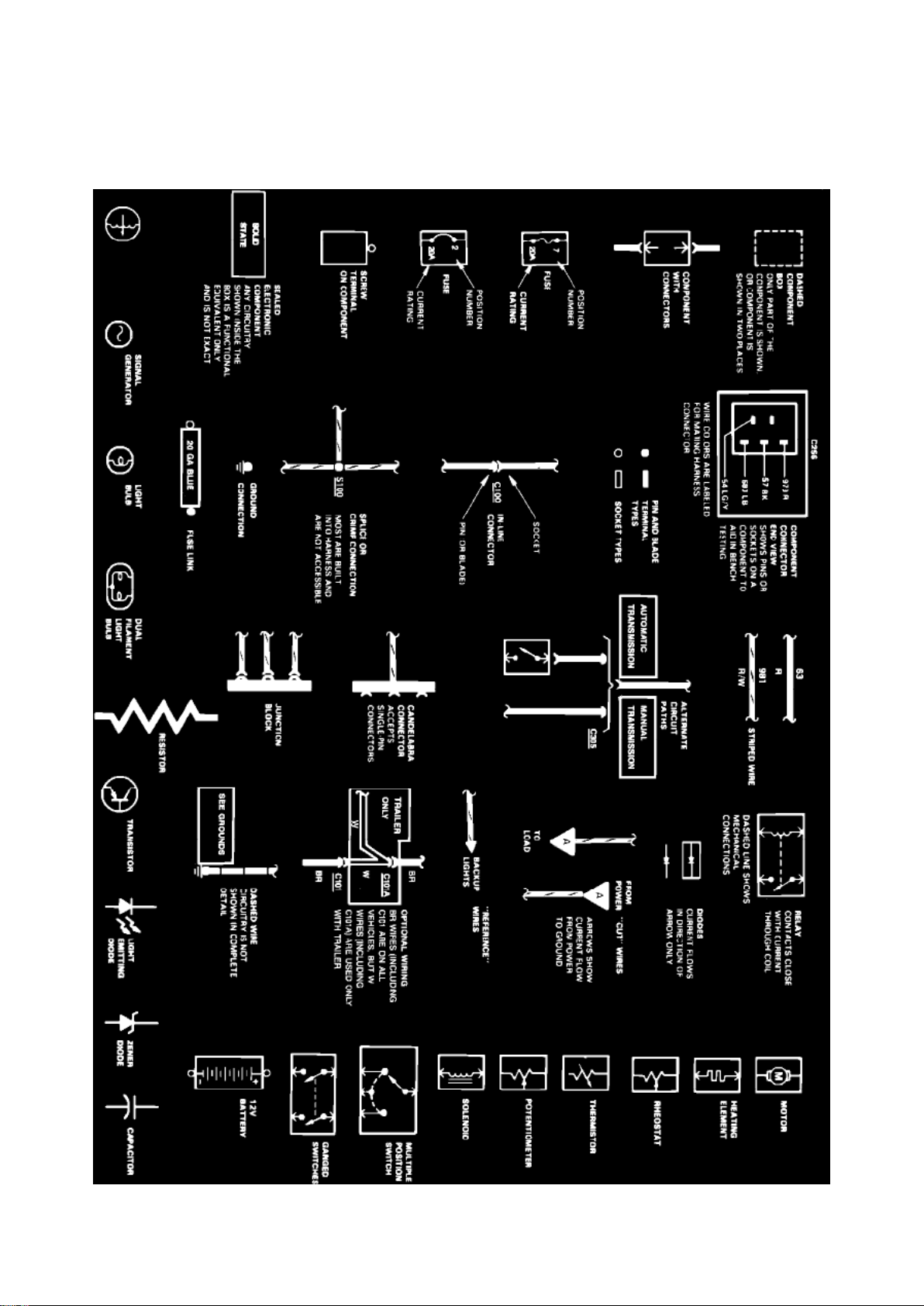
Windshield Washer Relay: Diagram Information and Instructions
Symbol Identification
Wire Color Code Identification
Page 51

Ford E 250 Van Workshop Manual (V8-6.9L DSL (1985))
Ford Workshop Manuals > Relays and Modules > Relays and Modules - Wiper and Washer Systems > Windshield Washer
Relay > Component Information > Diagrams > Diagram Information and Instructions > Page 78
Page 52

NOTE: Whenever a wire is labeled with two colors; the first color listed is the basic color of the
wire, and the second color is the tracer marking of the wire. If the second color is followed by by a
D, the tracer is dots. If the second color is followed by an H, the tracer is hash marks.
For example: BR/O is a brown wire with an orange stripe, R/Y D is a red wire with yellow dots and
BK/W H is a black wire with white hash marks.
BL: Blue BK: Black BR: Brown DB: Dark Blue DG: Dark Green GR: Green GY: Gray LB: Light Blue
LG: Light Green N:
Natural
O: Orange
PK: Pink R:
Red
P: Purple
T: Tan
V: Violet
W: White
Y: Yellow
Page 53
Ford E 250 Van Workshop Manual (V8-6.9L DSL (1985))
Ford Workshop Manuals > Relays and Modules > Relays and Modules - Wiper and Washer Systems > Windshield Washer
Relay > Component Information > Diagrams > Diagram Information and Instructions > Page 79
Page 54

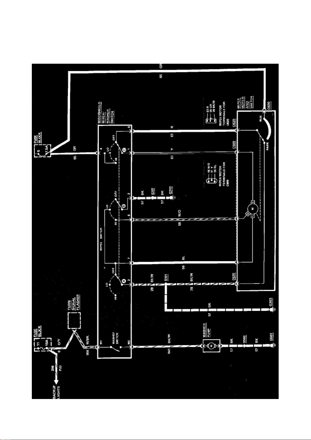
Windshield Washer Relay: Electrical Diagrams
Fig. 44 Windshield Wiper/Washer Wiring Circuit (Less Interval). 1985
Page 55
Ford E 250 Van Workshop Manual (V8-6.9L DSL (1985))
Ford Workshop Manuals > Relays and Modules > Relays and Modules - Wiper and Washer Systems > Windshield Washer
Relay > Component Information > Diagrams > Diagram Information and Instructions > Page 80
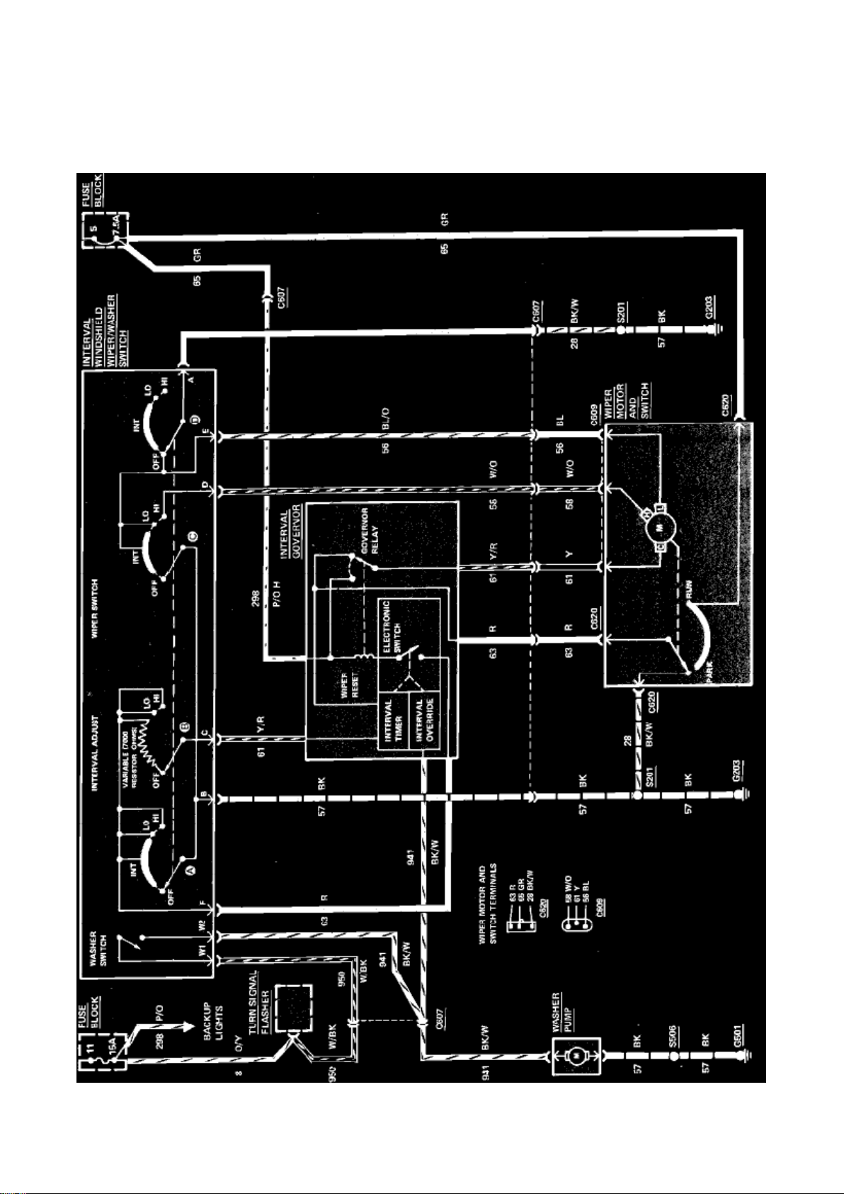
Page 56

Fig. 45 Windshield Wiper/Washer Wiring Circuit (With Interval). 1985
Page 57

Ford E 250 Van Workshop Manual (V8-6.9L DSL (1985))
Ford Workshop Manuals > Relays and Modules > Relays and Modules - Wiper and Washer Systems > Wiper Control
Module > Component Information > Locations
Page 58

Wiper Control Module: Locations
Upper LH Side Of I/P
Page 59
Ford E 250 Van Workshop Manual (V8-6.9L DSL (1985))
Ford Workshop Manuals > Relays and Modules > Relays and Modules - Wiper and Washer Systems > Wiper Relay >
Component Information > Diagrams > Diagram Information and Instructions
Page 60

Wiper Relay: Diagram Information and Instructions
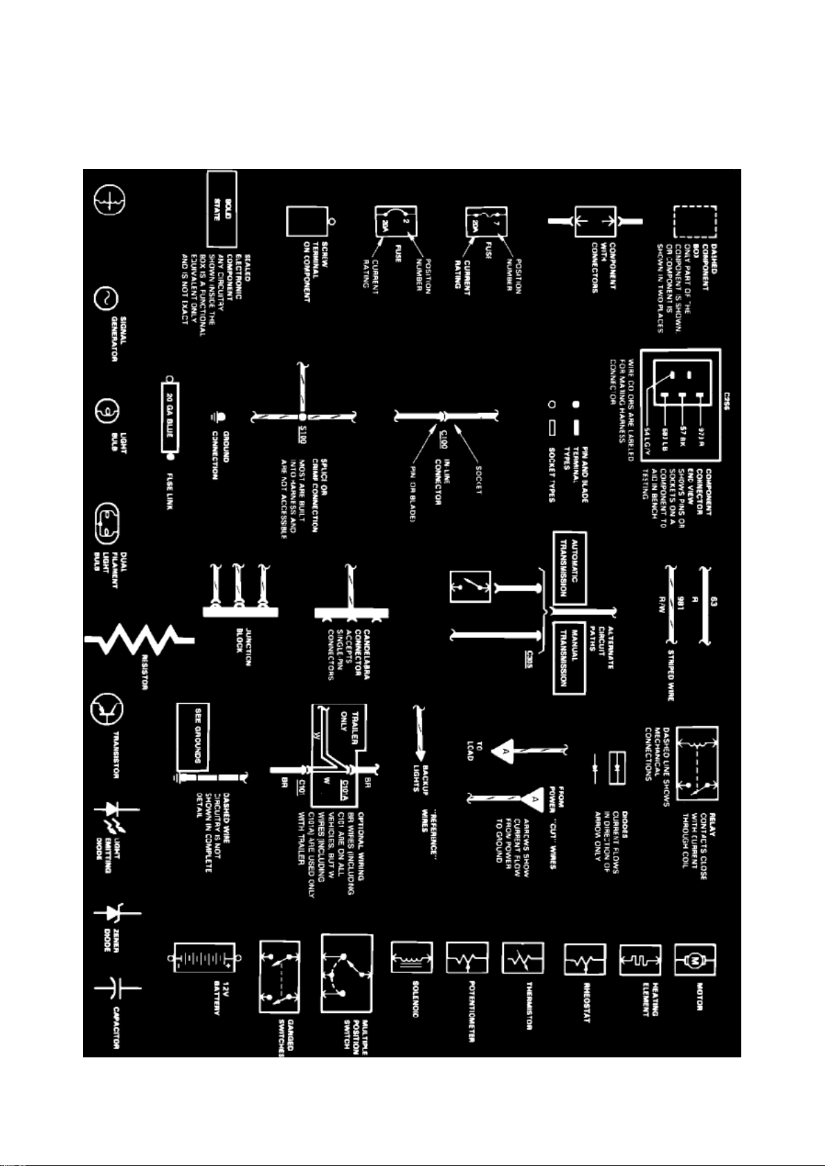
Symbol Identification
Wire Color Code Identification
Page 61

Ford E 250 Van Workshop Manual (V8-6.9L DSL (1985))
Ford Workshop Manuals > Relays and Modules > Relays and Modules - Wiper and Washer Systems > Wiper Relay >
Component Information > Diagrams > Diagram Information and Instructions > Page 88
Page 62

NOTE: Whenever a wire is labeled with two colors; the first color listed is the basic color of the
wire, and the second color is the tracer marking of the wire. If the second color is followed by by a
D, the tracer is dots. If the second color is followed by an H, the tracer is hash marks.
For example: BR/O is a brown wire with an orange stripe, R/Y D is a red wire with yellow dots and
BK/W H is a black wire with white hash marks.
BL: Blue BK: Black BR: Brown DB: Dark Blue DG: Dark Green GR: Green GY: Gray LB: Light Blue
LG: Light Green N:
Natural
O: Orange
PK: Pink R:
Red
P: Purple
T: Tan
V: Violet
W: White
Y: Yellow
Page 63
Ford E 250 Van Workshop Manual (V8-6.9L DSL (1985))
Ford Workshop Manuals > Relays and Modules > Relays and Modules - Wiper and Washer Systems > Wiper Relay >
Component Information > Diagrams > Diagram Information and Instructions > Page 89
Page 64

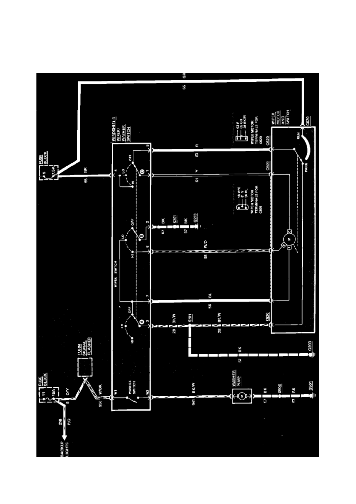
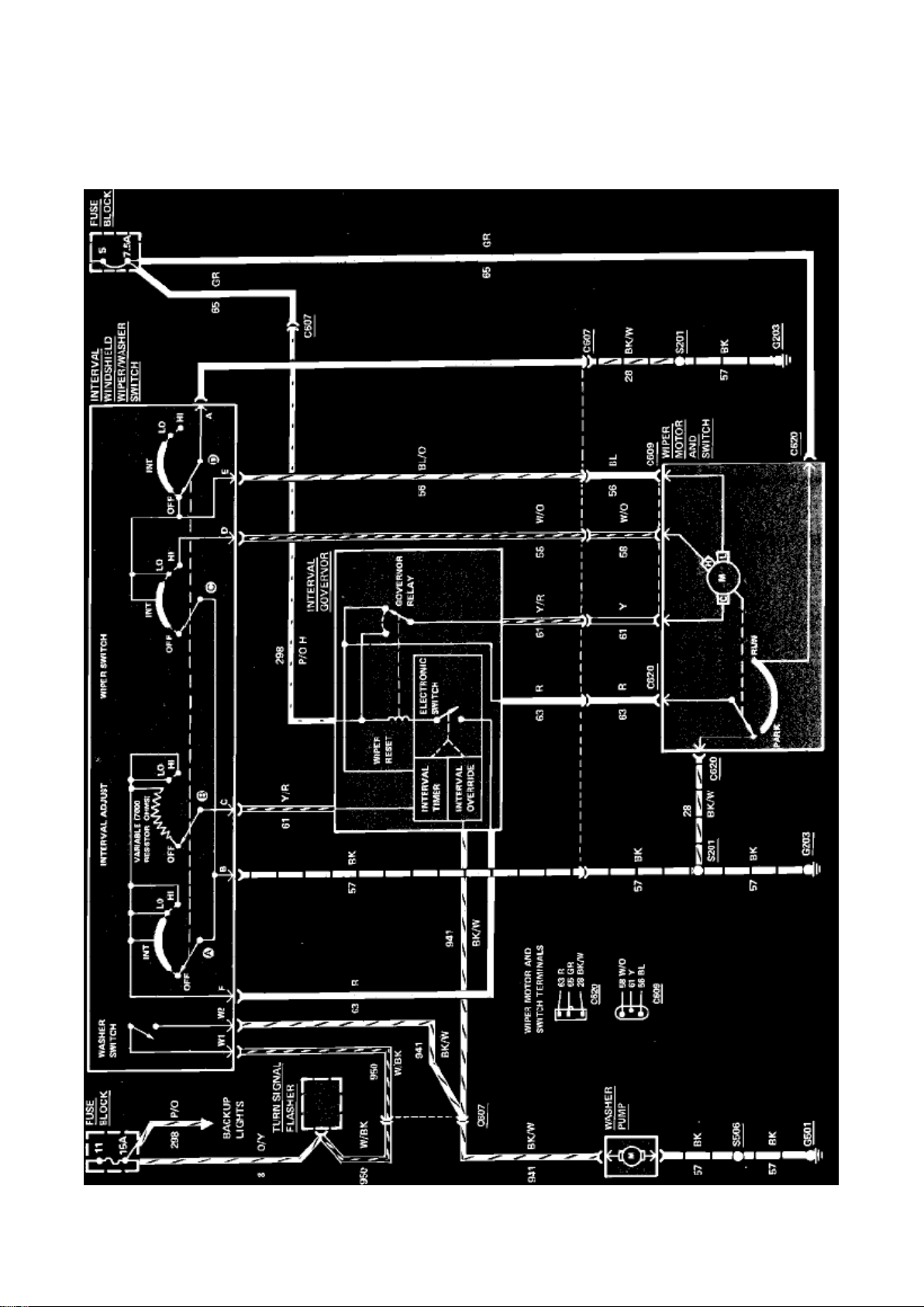
Wiper Relay: Electrical Diagrams
Fig. 44 Windshield Wiper/Washer Wiring Circuit (Less Interval). 1985
Page 65
Ford E 250 Van Workshop Manual (V8-6.9L DSL (1985))
Ford Workshop Manuals > Relays and Modules > Relays and Modules - Wiper and Washer Systems > Wiper Relay >
Component Information > Diagrams > Diagram Information and Instructions > Page 90
Page 66

Fig. 45 Windshield Wiper/Washer Wiring Circuit (With Interval). 1985
Page 67

Ford E 250 Van Workshop Manual (V8-6.9L DSL (1985))
Ford Workshop Manuals > Sensors and Switches > Sensors and Switches - Accessories and Optional Equipment > Radio
Power Boost Switch > Component Information > Locations
Page 68

Radio Power Boost Switch: Locations
Attached To RH Cowl
Page 69

Ford E 250 Van Workshop Manual (V8-6.9L DSL (1985))
Ford Workshop Manuals > Sensors and Switches > Sensors and Switches - Brakes and Traction Control > Brake Fluid
Pressure Sensor/Switch > Component Information > Technical Service Bulletins > Engine Compartment Wiring - Connector
Service
Page 70

Brake Fluid Pressure Sensor/Switch: Technical Service Bulletins Engine Compartment Wiring Connector Service
Page 71

Article No. 85-17-3
WIRING - ENGINE COMPARTMENT SERVICING TERMINALS/CONNECTORS ON 12A581 AND 14290 ASSEMBLIES FOR
INTERMITTENT CONCERNS
FORD 1985 ALL
LINCOLN-MERCURY 1985 ALL
LIGHT TRUCK 1985 ALL
When intermittent symptoms are reported and any of the components listed below are suspect,
then the following procedure should be performed before the start of normal diagnostics.
Component Connectors and Systems Affected:
^ TFI Ignition Module
^ Map Sensor
^ Air Vane Boost Control
^ Power Steering
^ ISC
^ Fuel Injector
^ Anti-Skid Pressure Switch
^ Anti-Skid Control Valve
^ Fluid Level Sensor
^ Main Hydraulic Valve
Terminal and Connector Inspection/Repair Procedure
1. Pull on each wire of the subject connector using approximately 3 to 5 lbs. force.
2. If the terminal pulls out of the connector, remove the terminal from wire and replace with a new
terminal.
3. Remove wedge from connector and install the new terminal and wire in the connector.
4. Replace the wedge and again pull on the wire. If the new terminal pulls out of connector, replace
connector.
A. Remove the wedge from connector and remove the remaining terminals, but leave the rubber
grommet on wires to aid in reinstalling the terminals in the correct position in the connector.
B. Reinstall all terminals into the new connector and reinstall the wedge.
C. Install the new connector making sure that it is fully seated to the mating connector (locking
fingers completely over ramp).
OTHER APPLICABLE ARTICLES: None WARRANTY STATUS: Reimbursable within the
provisions of the Warranty and Policy Manual. OPERATON:
Page 72

SP14290B85
TIME: 0.3 Hr. DLR. CODING: Basic Part No. 12A581 and/or 14290 - Code: 44
Page 73
Ford E 250 Van Workshop Manual (V8-6.9L DSL (1985))
Ford Workshop Manuals > Sensors and Switches > Sensors and Switches - Brakes and Traction Control > Brake Fluid
Pressure Sensor/Switch > Component Information > Technical Service Bulletins > Page 101
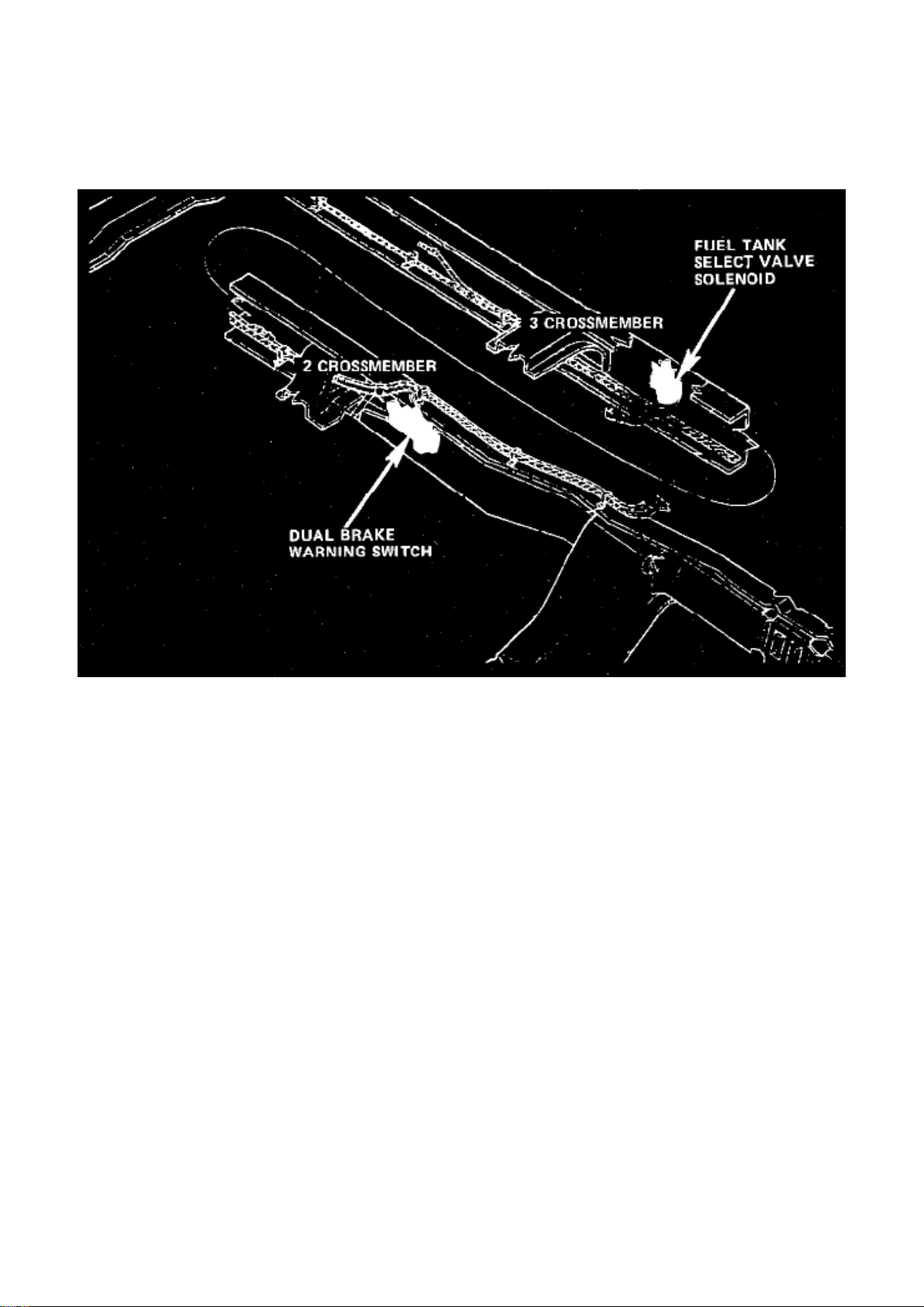
Brake Fluid Pressure Sensor/Switch: Locations
Frame Wiring.
On LH Frame At No. 2 Crossmember
Applicable to: 138 Standard Van
Page 74

Ford E 250 Van Workshop Manual (V8-6.9L DSL (1985))
Ford Workshop Manuals > Sensors and Switches > Sensors and Switches - Brakes and Traction Control > Parking Brake
Warning Switch > Component Information > Locations
Page 75

Parking Brake Warning Switch: Locations
Top Of Parking Brake Assembly
Page 76

Ford E 250 Van Workshop Manual (V8-6.9L DSL (1985))
Ford Workshop Manuals > Sensors and Switches > Sensors and Switches - Cooling System > Engine - Coolant
Temperature Sensor/Switch > Coolant Temperature Sensor/Switch (For Computer) > Component Information > Locations
Page 77

Coolant Temperature Sensor/Switch (For Computer): Locations
Top Forward RH Side Of Engine, Behind Water Outlet Casting
Page 78
Ford E 250 Van Workshop Manual (V8-6.9L DSL (1985))
Ford Workshop Manuals > Sensors and Switches > Sensors and Switches - Cooling System > Engine - Coolant
Temperature Sensor/Switch > Radiator Cooling Fan Temperature Sensor / Switch > Component Information >
Specifications
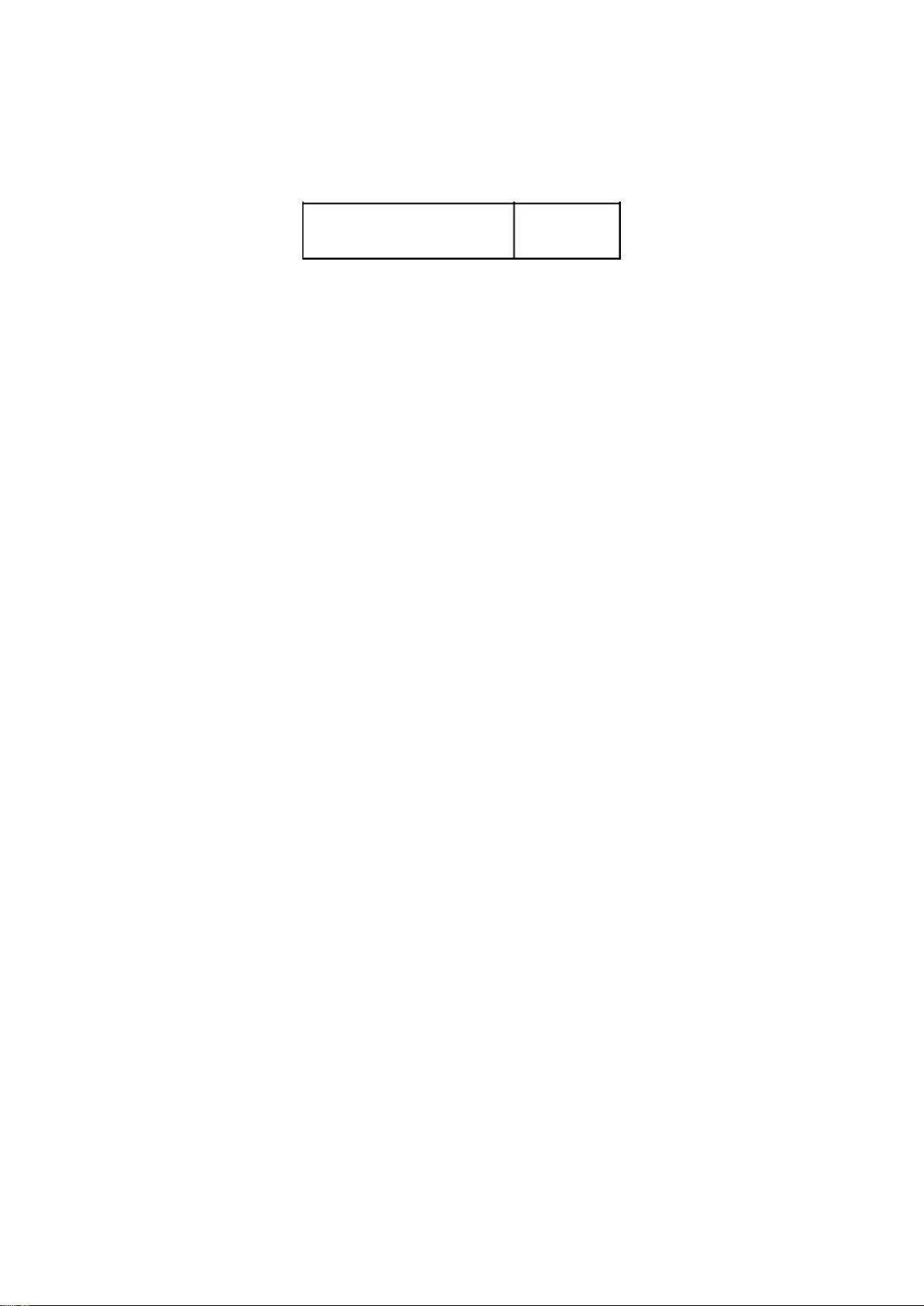
Radiator Cooling Fan Temperature Sensor / Switch: Specifications Switch Torque
Switch Torque
Cooling Fan Switch 8-18 ft.lb
Page 79
Ford E 250 Van Workshop Manual (V8-6.9L DSL (1985))
Ford Workshop Manuals > Sensors and Switches > Sensors and Switches - Cooling System > Engine - Coolant
Temperature Sensor/Switch > Temperature Sensor (Gauge) > Component Information > Locations
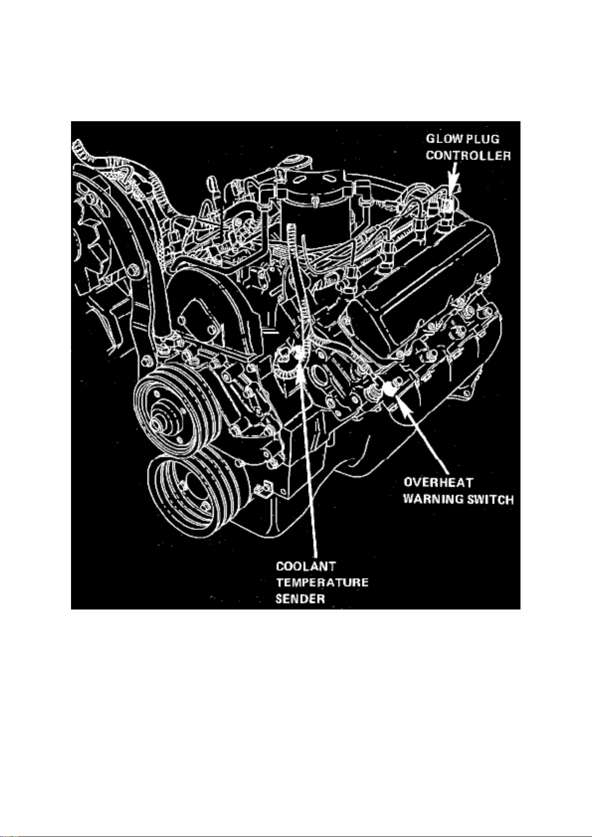
Temperature Sensor (Gauge): Locations
LH Side Of V8-420/6.
LH Front Side Of Intake Manifold
Page 80

Ford E 250 Van Workshop Manual (V8-6.9L DSL (1985))
Ford Workshop Manuals > Sensors and Switches > Sensors and Switches - Cooling System > Engine - Coolant
Temperature Sensor/Switch > Temperature Sensor (Gauge) > Component Information > Diagrams > Diagram Information
and Instructions
Page 81
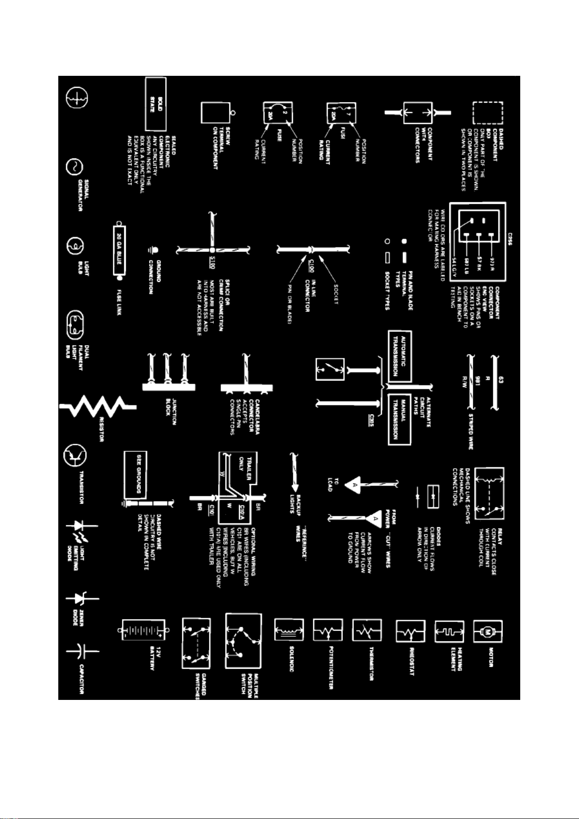
Temperature Sensor (Gauge): Diagram Information and Instructions
Page 82

Symbol Identification
Wire Color Code Identification
Page 83

Ford E 250 Van Workshop Manual (V8-6.9L DSL (1985))
Ford Workshop Manuals > Sensors and Switches > Sensors and Switches - Cooling System > Engine - Coolant
Temperature Sensor/Switch > Temperature Sensor (Gauge) > Component Information > Diagrams > Diagram Information
and Instructions > Page 118
Page 84

NOTE: Whenever a wire is labeled with two colors; the first color listed is the basic color of the
wire, and the second color is the tracer marking of the wire. If the second color is followed by by a
Page 85

D, the tracer is dots. If the second color is followed by an H, the tracer is hash marks.
For example: BR/O is a brown wire with an orange stripe, R/Y D is a red wire with yellow dots and
BK/W H is a black wire with white hash marks.
BL: Blue BK: Black BR: Brown DB: Dark Blue DG: Dark Green GR: Green GY: Gray LB: Light Blue
LG: Light Green N:
Natural
O: Orange
PK: Pink R:
Red
P: Purple
T: Tan
V: Violet
W: White
Y: Yellow
Page 86

Ford E 250 Van Workshop Manual (V8-6.9L DSL (1985))
Ford Workshop Manuals > Sensors and Switches > Sensors and Switches - Cooling System > Engine - Coolant
Temperature Sensor/Switch > Temperature Sensor (Gauge) > Component Information > Diagrams > Diagram Information
and Instructions > Page 119
Page 87
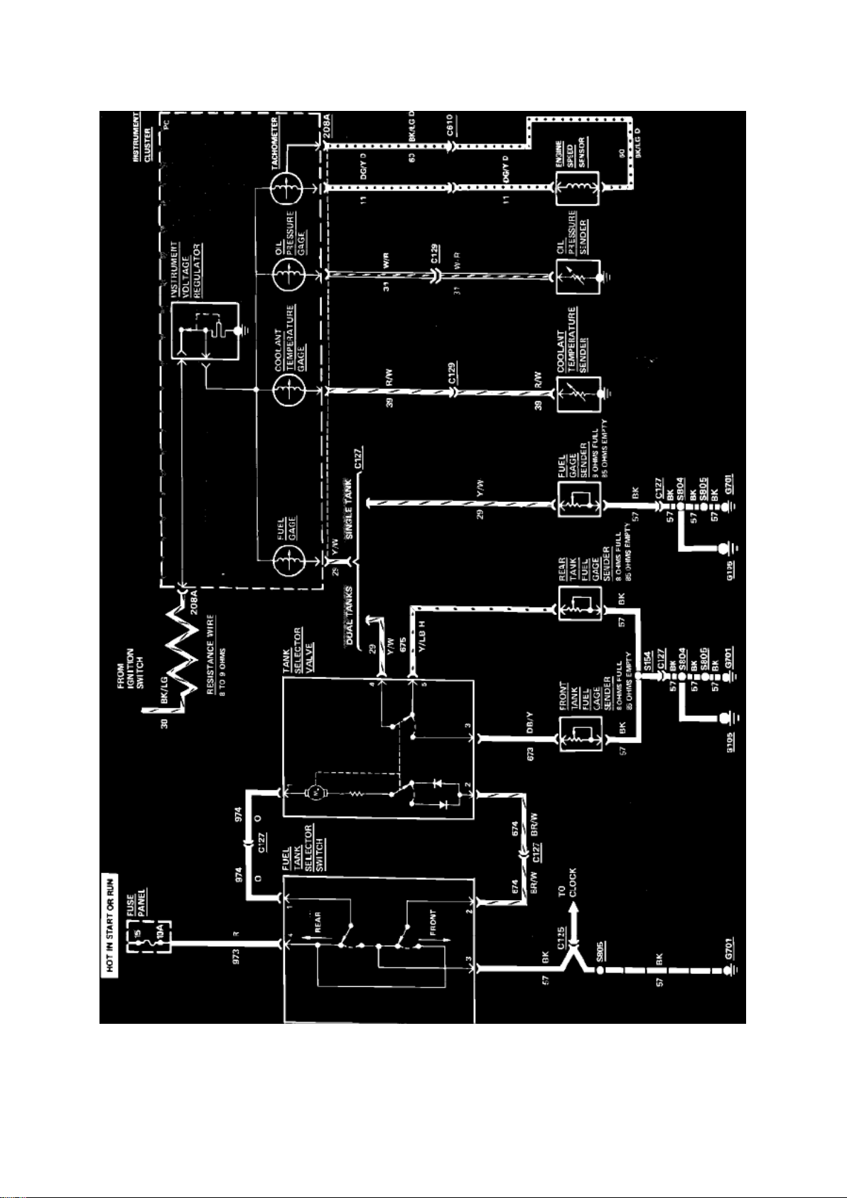
Fig. 32 Fuel Tank Selector & Gauges (Coolant, Fuel, Oil & Tachometer) Wiring Circuit. Diesel
Engine With Dual Tanks
Page 88
Ford E 250 Van Workshop Manual (V8-6.9L DSL (1985))
Ford Workshop Manuals > Sensors and Switches > Sensors and Switches - Cooling System > Engine - Coolant
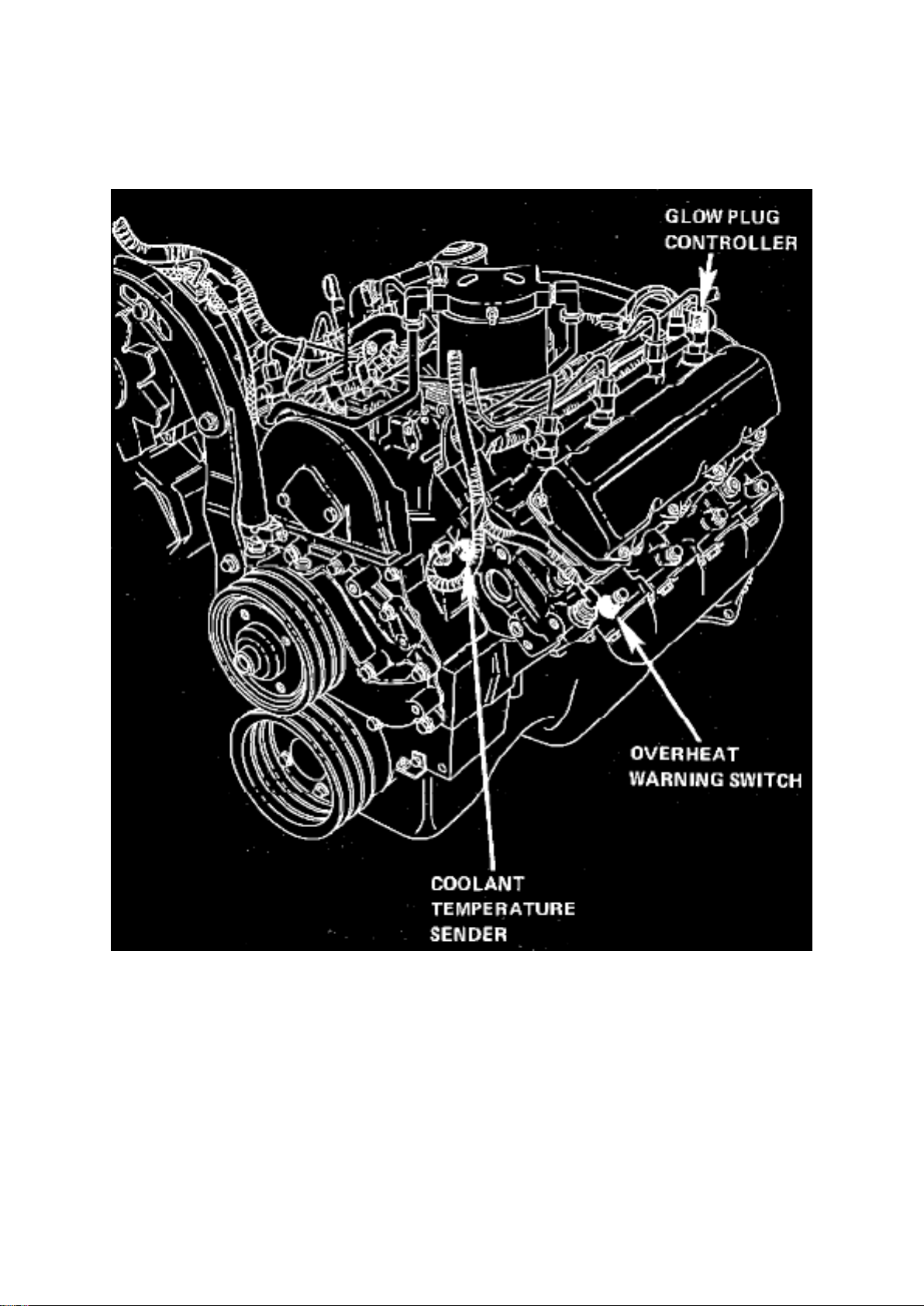
Temperature Sensor/Switch > Temperature Switch (Warning Indicator) > Component Information > Locations
LH Side Of V8-420/6.
Page 89

Ford E 250 Van Workshop Manual (V8-6.9L DSL (1985))
Ford Workshop Manuals > Sensors and Switches > Sensors and Switches - Cruise Control > Brake Switch (Cruise Control)
> Component Information > Testing and Inspection
Page 90

Brake Switch (Cruise Control): Testing and Inspection
Perform this test only when brake application will not disconnect the speed control system.
1. Check operation of stop lamps by applying approximately 6 lbs. of pressure to brake pedal. If
more than 6 lbs. is required, check brake pedal actuation and stop lamp switch.
2. If stop lamps do not function properly, check bulbs, circuit fuse or stop lamp switch.
3. If stop lamps function properly, check for battery voltage at 6 way connector using black wire
w/green stripe on 1980 models, 1981-83 E-100-350 and 1984-87 E-150-350 series, or white wire
w/pink stripe on 1981-82 F-100-350 and Bronco series, or white wire w/purple stripe on 1983
F-100-350, Bronco and Ranger, 1984-87 F-150-350, Ranger, 1984-87 Bronco II and 1986-87
Aerostar.
4. Depress brake pedal until stop lamps are illuminated. Check voltage at red wire w/black stripe on
1980 models, 1981-83 E-100-350 and 1984-87 E-150-350 models, or the light green wire on
1981-83 F-100-350 and Bronco, 1984-87 F-150-350 and Bronco, 1983-87 Ranger, 1984-87 Bronco
II and 1986-87 Aerostar. The difference between the two voltage readings must not exceed 1.5
volts. If voltage is greater, a high resistance exists in the circuit and must be found and corrected.
Page 91

Ford E 250 Van Workshop Manual (V8-6.9L DSL (1985))
Ford Workshop Manuals > Sensors and Switches > Sensors and Switches - Cruise Control > Clutch Switch, Cruise Control
> Component Information > Service and Repair
Page 92

Clutch Switch: Service and Repair
1. Remove bracket mounting screw(s).
2. Disconnect electrical connector and remove switch and bracket assembly.
3. Remove switch from bracket.
4. Reverse procedure to install.
Page 93

Ford E 250 Van Workshop Manual (V8-6.9L DSL (1985))
Ford Workshop Manuals > Sensors and Switches > Sensors and Switches - Cruise Control > Cruise Control Switch >
Component Information > Locations
Page 94

Cruise Control Switch: Locations
On Steering Wheel
Page 95
Ford E 250 Van Workshop Manual (V8-6.9L DSL (1985))
Ford Workshop Manuals > Sensors and Switches > Sensors and Switches - Cruise Control > Cruise Control Switch >
Component Information > Diagrams > Diagram Information and Instructions
Page 96

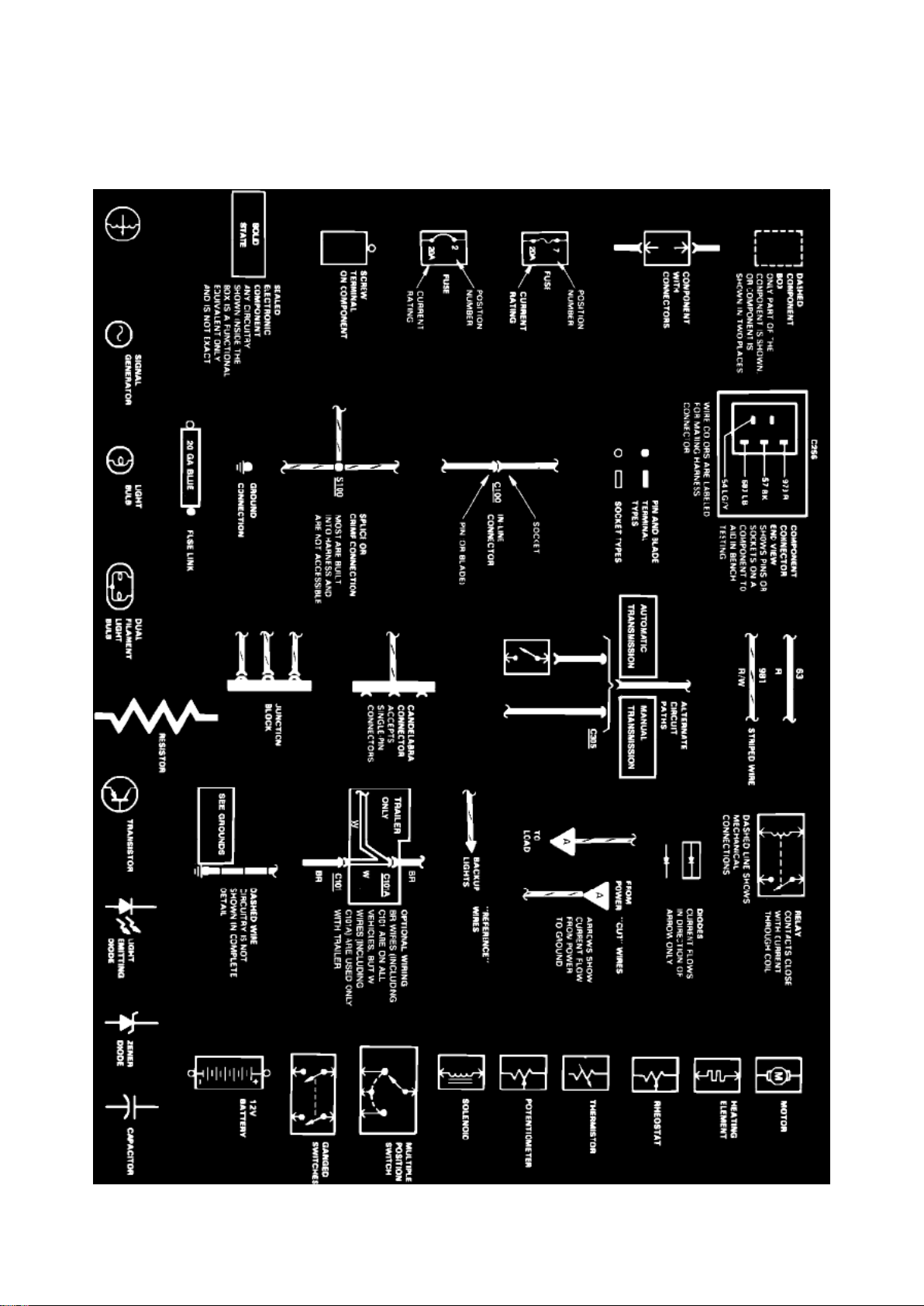
Cruise Control Switch: Diagram Information and Instructions
Symbol Identification
Wire Color Code Identification
Page 97

Ford E 250 Van Workshop Manual (V8-6.9L DSL (1985))
Ford Workshop Manuals > Sensors and Switches > Sensors and Switches - Cruise Control > Cruise Control Switch >
Component Information > Diagrams > Diagram Information and Instructions > Page 135
Page 98

NOTE: Whenever a wire is labeled with two colors; the first color listed is the basic color of the
wire, and the second color is the tracer marking of the wire. If the second color is followed by by a
D, the tracer is dots. If the second color is followed by an H, the tracer is hash marks.
For example: BR/O is a brown wire with an orange stripe, R/Y D is a red wire with yellow dots and
BK/W H is a black wire with white hash marks.
BL: Blue BK: Black BR: Brown DB: Dark Blue DG: Dark Green GR: Green GY: Gray LB: Light Blue
LG: Light Green N:
Natural
O: Orange
PK: Pink R:
Red
P: Purple
T: Tan
V: Violet
W: White
Y: Yellow
Page 99
Ford E 250 Van Workshop Manual (V8-6.9L DSL (1985))
Ford Workshop Manuals > Sensors and Switches > Sensors and Switches - Cruise Control > Cruise Control Switch >
Component Information > Diagrams > Diagram Information and Instructions > Page 136
Page 100

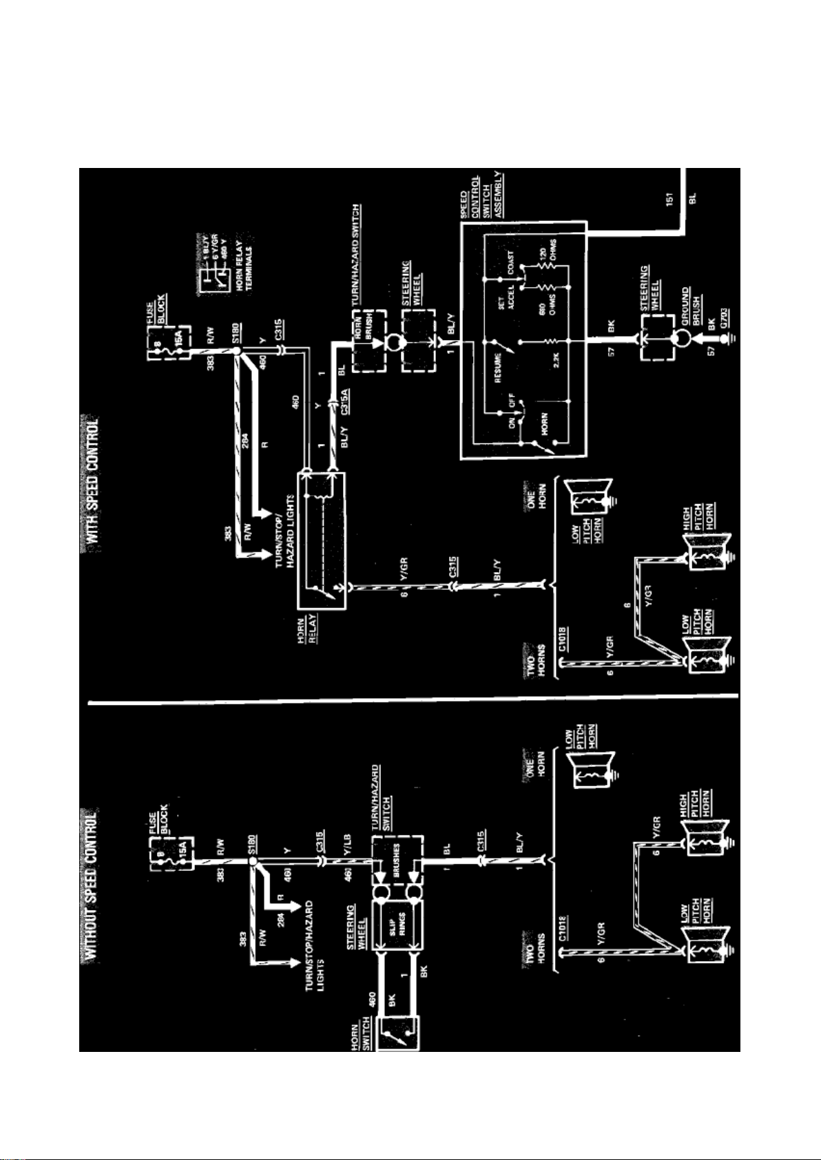
Cruise Control Switch: Electrical Diagrams
Horn & Speed Control Wiring Circuit (Part 1 of 2)
 Loading...