

Page 1

Factory Workshop Manual
Ford
Courier
L4-2299cc (1982)
Anonymous
1st January 2018
Make
Model
Engine and year
This manual was submitted by
Date
Page 2

Ford Courier Workshop Manual (L4-2299cc (1982))
Ford Workshop Manuals > A L L Diagnostic Trouble Codes ( DTC ) > Codes by System > A L L Diagnostic Trouble Codes Engine Controls > System Information > System Diagnosis > Transmisson Codes
Page 3

A L L Diagnostic Trouble Codes - Engine Controls: Testing and Inspection Transmisson Codes
For Transmission related codes, proceed to Computers and Control Systems.
Page 4

Ford Courier Workshop Manual (L4-2299cc (1982))
Ford Workshop Manuals > A L L Diagnostic Trouble Codes ( DTC ) > Codes by System > A L L Diagnostic Trouble Codes Trans and Drivetrain > System Information > System Diagnosis
Page 5

A L L Diagnostic Trouble Codes - Trans and Drivetrain: Testing and Inspection
For Transmission related codes, proceed to Computers and Control Systems.
Page 6
Ford Courier Workshop Manual (L4-2299cc (1982))
Ford Workshop Manuals > Relays and Modules > Relays and Modules - Powertrain Management > Relays and Modules Ignition System > Spark Control Relay > Component Information > Description and Operation
Spark Control Relay: Description and Operation
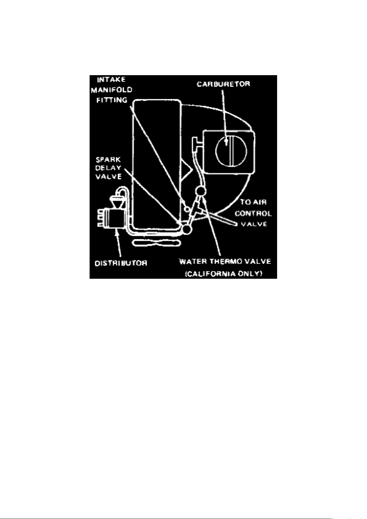
Fig. 37 - Spark Timing Control System
This system, Fig. 37, used on 1977-78 1.8 liter, 1979-82 2.0 liter and 1981-82 2.3 liter California
with manual transmission models reduces exhaust emissions by delaying vacuum to the distributor
vacuum advance unit during vehicle acceleration.
The system consists of a vacuum delay valve installed in the vacuum line between the carburetor
and distributor on 1.8 liter and 2.0 liter engines except California, or between the water thermo
valve and distributor on 2.0 liter California engines. On 2.3 liter engines, the system consists of a
spark delay valve (manual transmission equipped models) and a distributor solenoid valve installed
in the vacuum line between the intake manifold and distributor. The distributor solenoid valve is
controlled by a timer and water thermo switch (also a distributor water thermo switch on vehicles
with automatic transmission).
The spark delay valve has an internal restrictor to slow air flow in one direction and a check valve
which allows free air flow in the opposite direction.
On 1979-82 California models, distributor vacuum advance is restricted by the water thermo valve
which detects engine coolant temperature. This helps to warm up the catalytic converter.
Page 7
Ford Courier Workshop Manual (L4-2299cc (1982))
Ford Workshop Manuals > Relays and Modules > Relays and Modules - Powertrain Management > Relays and Modules Ignition System > Spark Control Relay > Component Information > Testing and Inspection > Spark Delay Valve
Page 8

Spark Control Relay: Testing and Inspection Spark Delay Valve
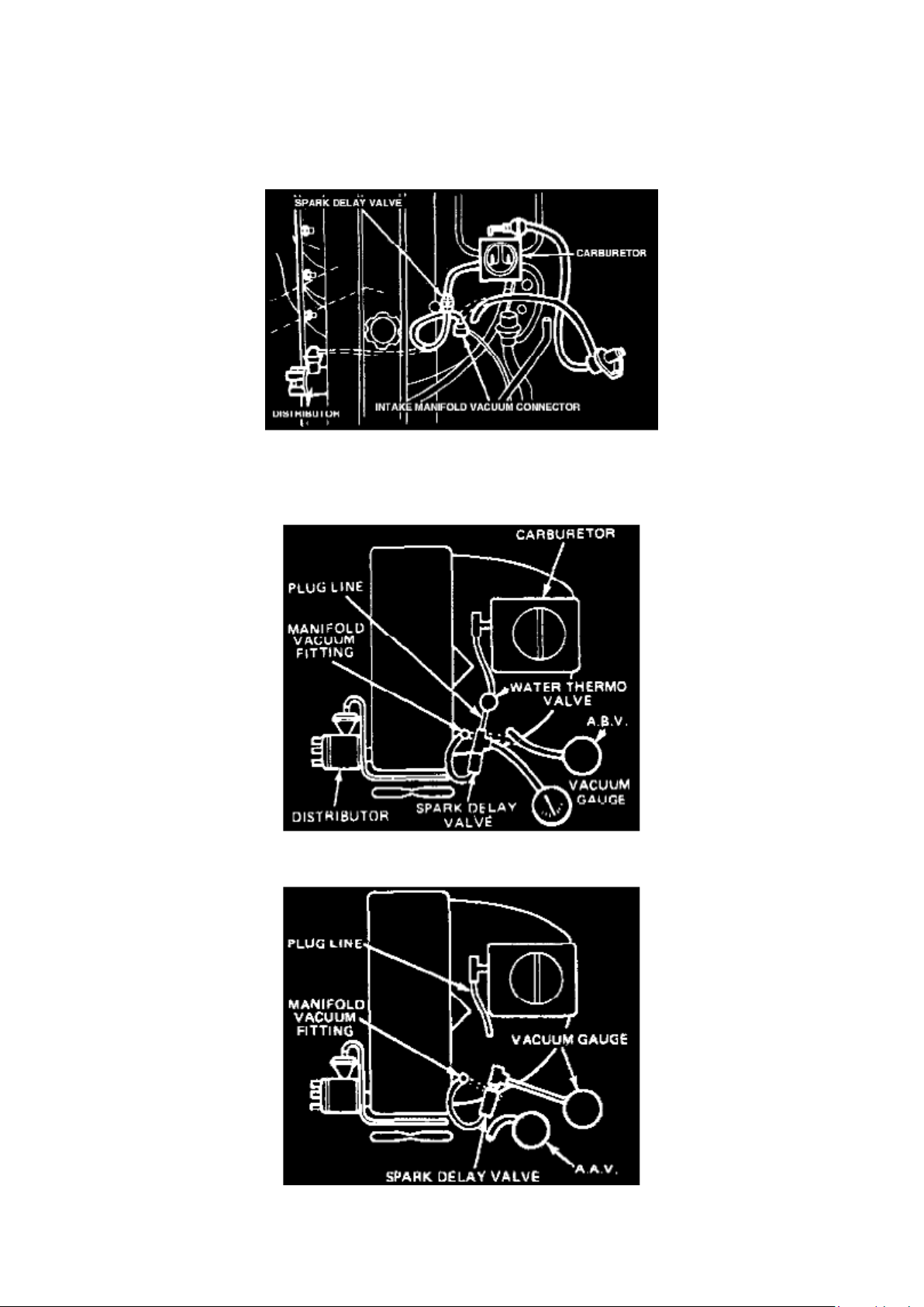
Spark Delay Valve, 1977-80, 1980-82 exc. Calif.
1. Remove air cleaner and disconnect vacuum line from distributor.
Fig. 38 - Spark Delay Valve Test
2. On 1977-78, disconnect vacuum control line at intake manifold fitting and install distributor
vacuum line to intake manifold fitting, Fig. 38.
Fig. 39 - Spark Delay Valve Test
Fig. 40 - Spark Delay Valve Test
3. On 1979-82, disconnect air bypass line on California models, Figs. 39 and 40, or air
anti-afterburn valve on except California models and connect
distributor vacuum line disconnected previously to intake manifold fitting.
Page 9
Ford Courier Workshop Manual (L4-2299cc (1982))
Ford Workshop Manuals > Relays and Modules > Relays and Modules - Powertrain Management > Relays and Modules Ignition System > Spark Control Relay > Component Information > Testing and Inspection > Spark Delay Valve > Page 19
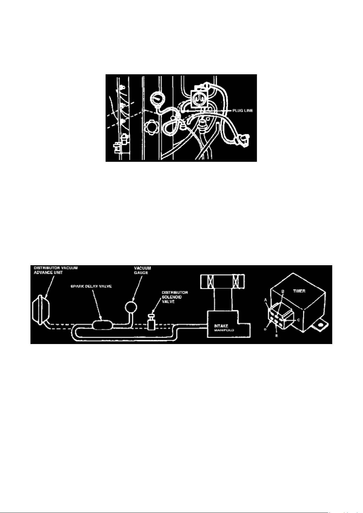
Fig. 41 - Spark Delay Valve Test
4. Remove vacuum line from carburetor side of vacuum delay valve, then plug in and connect a
vacuum gauge to vacuum delay valve, Figs. 39, 40
and 41.
5. Start engine and allow to idle.
6. Disconnect vacuum line from intake manifold fitting.
NOTE:The time required for vacuum reading to drop to 11.8 inches Hg. If amount of time is not
within 4-6 seconds, replace valve.
Spark Delay Valve, 1981-82 2.3L Calif, 1982 2.OL Calif.
Page 10

Fig. 42 - Spark Delay Valve Test
1. Disconnect vacuum sensing tube from spark delay valve at distributor solenoid and connect a
vacuum gauge to tube.
NOTE: On 1982 vehicles, add a 30mm vacuum reservoir between spark delay valve and vacuum
gauge.
2. Disconnect vacuum sensing tube from spark delay valve at distributor vacuum advance unit and
connect tube to intake manifold.
3. Start engine and note vacuum reading at idle.
4. Disconnect tube from intake manifold and check time required for vacuum reading to drop
decrease by 11.8 inches Hg. vacuum. Time required
should be 5 ± 1 seconds.
Page 11

Ford Courier Workshop Manual (L4-2299cc (1982))
Ford Workshop Manuals > Relays and Modules > Relays and Modules - Powertrain Management > Relays and Modules Ignition System > Spark Control Relay > Component Information > Testing and Inspection > Spark Delay Valve > Page 20
Page 12

Spark Control Relay: Testing and Inspection Distributor Solenoid Valve
1. Start engine and allow to idle.
2. Separate connector at distributor solenoid valve and apply battery voltage to the two terminals to
energize the solenoid.
3. Disconnect vacuum sensing tube from distributor solenoid valve at distributor vacuum advance.
4. Disconnect battery power from solenoid. Solenoid is functioning properly if vacuum is drawn into
vacuum sensing tube when battery is
disconnected.
Page 13
Ford Courier Workshop Manual (L4-2299cc (1982))
Ford Workshop Manuals > Relays and Modules > Relays and Modules - Powertrain Management > Relays and Modules Ignition System > Spark Control Relay > Component Information > Testing and Inspection > Spark Delay Valve > Page 21
Spark Control Relay: Testing and Inspection Spark Control Timer
Timer Test, 2.3L Calif.
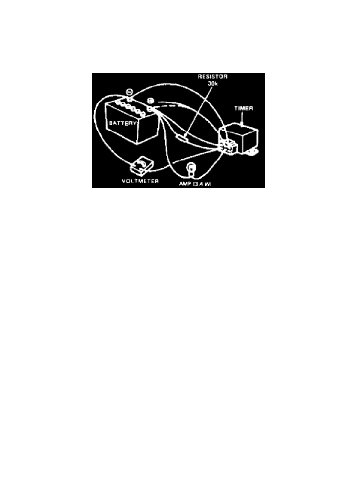
Fig. 43 - Timer Test
1. Remove timer.
2. Connect suitable test wires to timer terminals A, B and C respectively.
3. Connect a suitable test wire with a 30K ohm resistor to terminal D.
4. Connect a suitable test wire with a 3.4 watt lamp to terminal E.
5. Connect positive leads of a voltmeter to terminal D and negative test lead to battery negative
terminal.
6. Connect test wires from timer terminals A, D and E to battery positive terminal. Do not connect
test wire from terminal B at this time.
7. Connect wire from terminal C to battery negative terminal.
8. Voltmeter should not read 6 volts.
9. Connect test wire from timer terminal B with battery positive terminal. At the instant the
connection is made, the volt. meter should read less than
1 volt and lamp should illuminate. Maintain this connection for 125 ± 15 seconds. Voltmeter should
read 8 volts.
Page 14

Ford Courier Workshop Manual (L4-2299cc (1982))
Ford Workshop Manuals > Relays and Modules > Relays and Modules - Powertrain Management > Relays and Modules Ignition System > Spark Control Relay > Component Information > Testing and Inspection > Spark Delay Valve > Page 22
Page 15

Spark Control Relay: Testing and Inspection Water Thermo Switch
Water Thermo Switch, 2.3L Calif.
1. Remove thermo switch.
2. Connect an ohmmeter across the switch terminals and place sensor end of switch in a water
filled container. Place a thermometer into water and
gradually heat water while observing thermometer.
3. Note temperature at which continuity exists between switch terminals. The specified temperature
is 131 ±4°F. Replace switch if temperature is not
within specifications.
Distributor Water Thermo Switch, 2.3L With Auto. Trans., Calif.
The procedure to test this switch is the same as the one described previously for the Water Thermo
Switch, 2.3L Calif. However, the specified temperature is 50 ±4°F or above.
Page 16

Ford Courier Workshop Manual (L4-2299cc (1982))
Ford Workshop Manuals > Sensors and Switches > Sensors and Switches - Cooling System > Engine - Coolant
Temperature Sensor/Switch > Radiator Cooling Fan Temperature Sensor / Switch > Component Information >
Specifications
Radiator Cooling Fan Temperature Sensor / Switch: Specifications Switch Torque
Switch Torque
Cooling Fan Switch 8-18 ft.lb
Page 17

Ford Courier Workshop Manual (L4-2299cc (1982))
Ford Workshop Manuals > Sensors and Switches > Sensors and Switches - Wiper and Washer Systems > Washer Fluid
Level Switch > Component Information > Technical Service Bulletins > Customer Interest for Washer Fluid Level Switch: >
84219 > Oct > 84 > Wiper/Washer - Low Fluid Warning Light Stays On
Page 18

Washer Fluid Level Switch: Customer Interest Wiper/Washer - Low Fluid Warning Light Stays On
Page 19

Article No. 84-21-9
WIPER/WASHER - LOW FLUID WARNING LIGHT STAYS ON
FORD ALL MODEL YEARS AND ALL CAR LINES WITH LOW FLUID WARNING LIGHT
LINCOLN-MERCURY ALL MODEL YEARS AND ALL CAR LINES WITH LOW FLUID WARNING
LIGHT
LIGHT TRUCKS ALL MODEL YEARS AND ALL LINES WITH LOW FLUID WARNING LIGHT
On some vehicles equipped with low fluid warning light, the light may stay on even when the
washer reservoir is full. This is caused by using washer fluid concentrate (C9AZ-19550-A/B) that
has not been mixed with water according to the instructions. The undiluted washer solution is
absorbed by the float resulting in the float sinking.
When filling the washer reservoir with washer fluid concentrate (C9AZ-19550-A/B), the instructions
on the can must be followed. Mixing the concentrated washer fluid with water will stop the float
from sinking.
OTHER APPLICABLE ARTICLES: None WARRANTY STATUS: "INFORMATION ONLY"
Page 20

Ford Courier Workshop Manual (L4-2299cc (1982))
Ford Workshop Manuals > Sensors and Switches > Sensors and Switches - Wiper and Washer Systems > Washer Fluid
Level Switch > Component Information > Technical Service Bulletins > All Technical Service Bulletins for Washer Fluid
Level Switch: > 84219 > Oct > 84 > Wiper/Washer - Low Fluid Warning Light Stays On
Page 21

Washer Fluid Level Switch: All Technical Service Bulletins Wiper/Washer - Low Fluid Warning Light
Stays On
Page 22

Article No. 84-21-9
WIPER/WASHER - LOW FLUID WARNING LIGHT STAYS ON
FORD ALL MODEL YEARS AND ALL CAR LINES WITH LOW FLUID WARNING LIGHT
LINCOLN-MERCURY ALL MODEL YEARS AND ALL CAR LINES WITH LOW FLUID WARNING
LIGHT
LIGHT TRUCKS ALL MODEL YEARS AND ALL LINES WITH LOW FLUID WARNING LIGHT
On some vehicles equipped with low fluid warning light, the light may stay on even when the
washer reservoir is full. This is caused by using washer fluid concentrate (C9AZ-19550-A/B) that
has not been mixed with water according to the instructions. The undiluted washer solution is
absorbed by the float resulting in the float sinking.
When filling the washer reservoir with washer fluid concentrate (C9AZ-19550-A/B), the instructions
on the can must be followed. Mixing the concentrated washer fluid with water will stop the float
from sinking.
OTHER APPLICABLE ARTICLES: None WARRANTY STATUS: "INFORMATION ONLY"
Page 23

Ford Courier Workshop Manual (L4-2299cc (1982))
Ford Workshop Manuals > Maintenance > Alignment > System Information > Specifications
Page 24

Alignment: Specifications
Caster
Standard ..............................................................................................................................................
......................................................... +3/4° - 1 1/4°
Camber
Standard ..............................................................................................................................................
......................................................... +1/2° - 1 1/4°
Toe-inches
Standard ..............................................................................................................................................
.................................................................. 0" - 1/4"
Page 25

Ford Courier Workshop Manual (L4-2299cc (1982))
Ford Workshop Manuals > Maintenance > Tune-up and Engine Performance Checks > Fuel Pressure > System Information
> Specifications
Page 26

Fuel Pressure: Specifications
FUEL PRESSURE
Pump Pressure ....................................................................................................................................
................................................................ 2.8 - 3.6 psi
Page 27

Ford Courier Workshop Manual (L4-2299cc (1982))
Ford Workshop Manuals > Maintenance > Tune-up and Engine Performance Checks > Fuel Filter > Component Information
> Technical Service Bulletins > Fuel Filter - Replacement Information
Page 28

Fuel Filter: Technical Service Bulletins Fuel Filter - Replacement Information
Article No. 85-6-10
FUEL FILTER REPLACEMENT INFORMATION - ALL WITH FUEL FILTERS ATTACHED TO THE
CARBURETOR AND/OR FUEL LINE WITH A RUBBER HOSE
FORD ALL 1985 AND PRIOR
LINCOLN-MERCURY ALL 1985 AND PRIOR
LIGHT TRUCK ALL 1985 AND PRIOR
New fuel connector hoses and clamps should be used whenever a fuel filter is replaced.
Due to possible deterioration of hose materials which may result if a vehicle is fueled with gasoline
containing excessive levels of methanol or ethanol, a new fuel hose and clamps should be installed
when the fuel filter is changed. DO NOT REUSE OLD HOSES OR CLAMPS.
OTHER APPLICABLE ARTICLES: NONE WARRANTY STATUS: "INFORMATION ONLY"
Page 29

Ford Courier Workshop Manual (L4-2299cc (1982))
Ford Workshop Manuals > Maintenance > Filters > Fuel Filter > Component Information > Technical Service Bulletins >
Fuel Filter - Replacement Information
Page 30

Fuel Filter: Technical Service Bulletins Fuel Filter - Replacement Information
Article No. 85-6-10
FUEL FILTER REPLACEMENT INFORMATION - ALL WITH FUEL FILTERS ATTACHED TO THE
CARBURETOR AND/OR FUEL LINE WITH A RUBBER HOSE
FORD ALL 1985 AND PRIOR
LINCOLN-MERCURY ALL 1985 AND PRIOR
LIGHT TRUCK ALL 1985 AND PRIOR
New fuel connector hoses and clamps should be used whenever a fuel filter is replaced.
Due to possible deterioration of hose materials which may result if a vehicle is fueled with gasoline
containing excessive levels of methanol or ethanol, a new fuel hose and clamps should be installed
when the fuel filter is changed. DO NOT REUSE OLD HOSES OR CLAMPS.
OTHER APPLICABLE ARTICLES: NONE WARRANTY STATUS: "INFORMATION ONLY"
Page 31

Ford Courier Workshop Manual (L4-2299cc (1982))
Ford Workshop Manuals > Maintenance > Hoses > System Information > Service Precautions
Page 32

Hoses: Service Precautions
SERVICE PRECAUTIONS
To prevent vehicle damage, always observe the following precautions: After servicing a hose, check for leaks before and after test driving the vehicle.
- Always use the correct size hose. Do not use standard sized hose in place of metric hose or vice
versa.
Always use the correct type of hose. Never use vacuum hose in place of fuel hose. Never use
heater hose in place of PCV hose.
- When replacing hoses which are attached to the engine on one end and the frame or body on the
other end, always leave sufficient length to compensate for engine movement (from torque).
Page 33

Ford Courier Workshop Manual (L4-2299cc (1982))
Ford Workshop Manuals > Maintenance > Fluids > Coolant > Component Information > Technical Service Bulletins >
Recycled Engine Coolant - Service Tips
Page 34

Coolant: Technical Service Bulletins Recycled Engine Coolant - Service Tips
Article No. 95-18-2
09/11/95
^ COOLANT - USE OF RECYCLED ENGINE, COOLANT - SERVICE TIP
^ COOLING SYSTEM - USE OF RECYCLED ENGINE, COOLANT - SERVICE TIP
FORD: 1980 and after CROWN VICTORIA, MUSTANG, THUNDERBIRD 1981 and after ESCORT
1982-88 EXP 1984-94 TEMPO 1986 and after TAURUS 1988-93 FESTIVA 1989 and after PROBE
1994 and after ASPIRE 1995 and after CONTOUR
LINCOLN-MERCURY: 1980 and after CONTINENTAL, COUGAR, GRAND MARQUIS, TOWN
CAR 1981-86 CAPRI 1981-87 LYNX 1984-92 MARK VII 1984-94 TOPAZ 1986 and after SABLE
1987-89 TRACER 1991-94 CAPRI 1991 and after TRACER 1993 and after MARK VIII 1995 and
after MYSTIQUE
MERKUR: 1985-89 XR4TI 1988-89 SCORPIO
LIGHT TRUCK: 1980 and after F-150-350 SERIES 1981 and after ECONOLINE 1982 and after
BRONCO 1983 and after RANGER 1984-90 BRONCO II 1986 and after AEROSTAR 1988 and
after F SUPER DUTY 1991 and after EXPLORER 1993 and after VILLAGER 1995 and after
WINDSTAR
This TSB is being republished in its entirety to include warranty information when using recycled
coolant
ISSUE: Ford Motor Company authorizes the use of recycled engine coolant that, when properly
processed and reinhibited, meets Ford specification ESE-M97B44-A. At this time, the Rotunda
Coolant Recycler (181-00003) process is the only approved coolant recycling method available
through Ford that is capable of producing recycled engine coolant that meets Ford specification
ESE-M97B44-A.
ACTION: Refer to the following Service Procedure for coolant processing and reinhibiting using
Rotunda Coolant Recycler (181-00003).
NOTE:
WHILE TESTING SHOWS THAT RECYCLED ENGINE COOLANT CAN PROVIDE ACCEPTABLE
PERFORMANCE, THE COOLANT PRODUCED FROM ROTUNDA EQUIPMENT IS INTENDED
FOR USE WITHIN DEALERSHIPS ON WARRANTY AND CUSTOMER PAY REPAIRS ONLY
AND NOT INTENDED FOR RETAIL SALE. THERE ARE REGULATORY, PACKAGING AND
LABELING CONCERNS
Page 35

Ford Courier Workshop Manual (L4-2299cc (1982))
Ford Workshop Manuals > Maintenance > Fluids > Coolant > Component Information > Technical Service Bulletins >
Recycled Engine Coolant - Service Tips > Page 68
Page 36

ASSOCIATED WITH THE RETAIL SALE OF CHEMICAL PRODUCTS.
CAUTION:
THE REINHIBITOR CHEMICALS PROVIDED WITH THIS EQUIPMENT ARE NOT
APPROPRIATE FOR USE ON MEDIUM/HEAVY TRUCK APPLICATIONS.
WARNING:
ROTUNDA PREMIUM COOLANT REINHIBITORS # 1 AND # 2 HAVE BEEN SPECIFICALLY
FORMULATED TO WORK WITH ROTUNDA COOLANT RECYCLER (181-00003).
USE OF ANY OTHER CHEMICAL ADDITIVES WITH THIS SYSTEM WILL VOID ALL
WARRANTIES FOR THE EQUIPMENT AND FOR THE FINAL COOLANT PRODUCT.
SERVICE PROCEDURE
DIRECTIONS FOR PROCESSING USED ENGINE COOLANT WITH ROTUNDA COOLANT
RECYCLER
1. Close the drain valve on the unit.
2. Open the fill valve.
3. Pour used engine coolant into the funnel on the side of the unit.
NOTE:
MAXIMUM CAPACITY 15 25 GALLONS (95 L).
4. Insert the outlet hoses of the recycler into clean, properly labeled containers. One (1) container
is for the outlet process water and the other container is for distilled ethylene glycol.
5. Push the "ON" switch on the front to start the operation. The unit will process 1 gallon (3.8 L) per
hour of operation and will automatically shut off when cycle is complete.
6. Add reinhibitor following the directions in this article.
7. Open the drain valve to drain the residue from the distillation vessel. Dispose of residue in
accordance with all local. state and federal regulations.
ADDING REINHIBITOR CHEMICALS
1. Process the coolant according to the directions listed in this article
2. Thoroughly mix 4 fl oz (118 ml) of Reinhibitor # 1 to each gallon of distilled ethylene glycol.
3. Thoroughly mix 4 fl oz (118 ml) of Reinhibitor # 2 to each gallon of distilled ethylene glycol.
4. Mix well.
5. Check the pH level of the coolant. The pH level must be between 9 and 11.
6. Add enough water to the concentrated coolant to produce a 50/50 mixture of coolant and water.
NOTE:
THE CONCENTRATED COOLANT MUST BE MIXED WITH WATER TO MEET THE
NECESSARY ENGINE FREEZE PROTECTION.
Page 37

7. Check the coolant freeze point of the 50% coolant solution. Freeze point should be -34°F
(-37°C).
Consult the Rotunda Coolant Recycler Manual for more detailed operating instructions. Call
1-800-ROTUNDA, 8 AM to 8 PM EST, for inquiries regarding the Rotunda Coolant Recycler and to
order the Reinhibitor (187-R0001).
PART NUMBER PART NAME
Rotunda # 187-R0001 Rotunda Premium Coolant Reinhibitor
WARRANTY CLAIMS: Dealer can claim recycled engine coolant by Ford approved process via a
warranty repair on an 1863 claim as follows:
Part Number: RECCOOL (not a valid part number, but it is recognized on an 1863 claim).
Page 38

Ford Courier Workshop Manual (L4-2299cc (1982))
Ford Workshop Manuals > Maintenance > Fluids > Coolant > Component Information > Technical Service Bulletins >
Recycled Engine Coolant - Service Tips > Page 69
Page 39

Quantity: Indicate the number of QUARTS of recycled coolant used.
OTHER APPLICABLE ARTICLES: NONE SUPERSEDES: 95-16-6 WARRANTY STATUS:
INFORMATION ONLY OASIS CODES: 402000
Page 40

Ford Courier Workshop Manual (L4-2299cc (1982))
Ford Workshop Manuals > Maintenance > Fluids > Coolant > Component Information > Specifications > Capacity
Specifications
Page 41

Coolant: Capacity Specifications
Coolant Capacity 8.8 qts
..............................................................................................................................................................
.........................................
Page 42

Ford Courier Workshop Manual (L4-2299cc (1982))
Ford Workshop Manuals > Maintenance > Fluids > Coolant > Component Information > Specifications > Capacity
Specifications > Page 72
Page 43

Coolant: Fluid Type Specifications
COOLING SYSTEM FLUID, PREMIUM
Ford Part No.
U.S.A (Except Oregon)
............................................................................................................................................................
E2FZ-19549-AA or -B Canada ............................................................................................................
.............................................................................................. CXC-8-B Oregon ..................................
.............................................................................................................................................................
F5FZ-19549-CC
Ford Specification ................................................................................................................................
................................................... ESE-M97B44-A
COOLING SYSTEM FLUSH
Ford Part No. .......................................................................................................................................
................................................... F1AZ-19A503-A Ford Specification .................................................
..................................................................................................................................... ESR-M14P7-A
Coolant Mixture with Water .................................................................................................................
...................................................................... 50%
Warning: Do not mix coolant types. Check the owners manual or refer to your local dealer for the
correct coolant type.
Page 44
Ford Courier Workshop Manual (L4-2299cc (1982))
Ford Workshop Manuals > Maintenance > Fluids > Engine Oil > Component Information > Technical Service Bulletins >
Engine - Oil Level Checking Procedure
Engine Oil: Technical Service Bulletins Engine - Oil Level Checking Procedure
Article No. 85-25-20
OIL DIPSTICK - ENGINE OIL LEVEL CHECKING PROCEDURE - GASOLINE ENGINES
LIGHT TRUCK 1986 AND PRIOR
MEDIUM/HEAVY TRUCK 1986 AND PRIOR
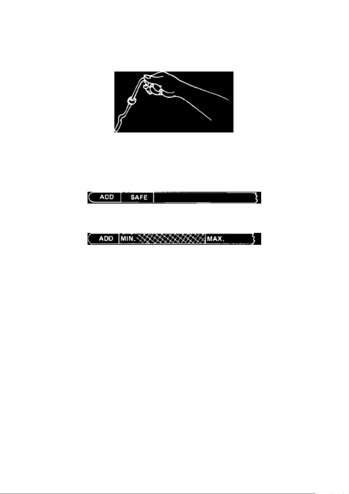
Figure 17 - Dipstick
To correctly check the engine oil level, the vehicle must be parked on a level surface. Allow a few
minutes after shutting the engine off for oil to drain down before checking. For consistent oil level
readings, insert the dipstick with the loop of the handle as shown in Figure 17.
Figure 18 - Dipstick - Calibration
Figure 19 - Dipstick - Calibration
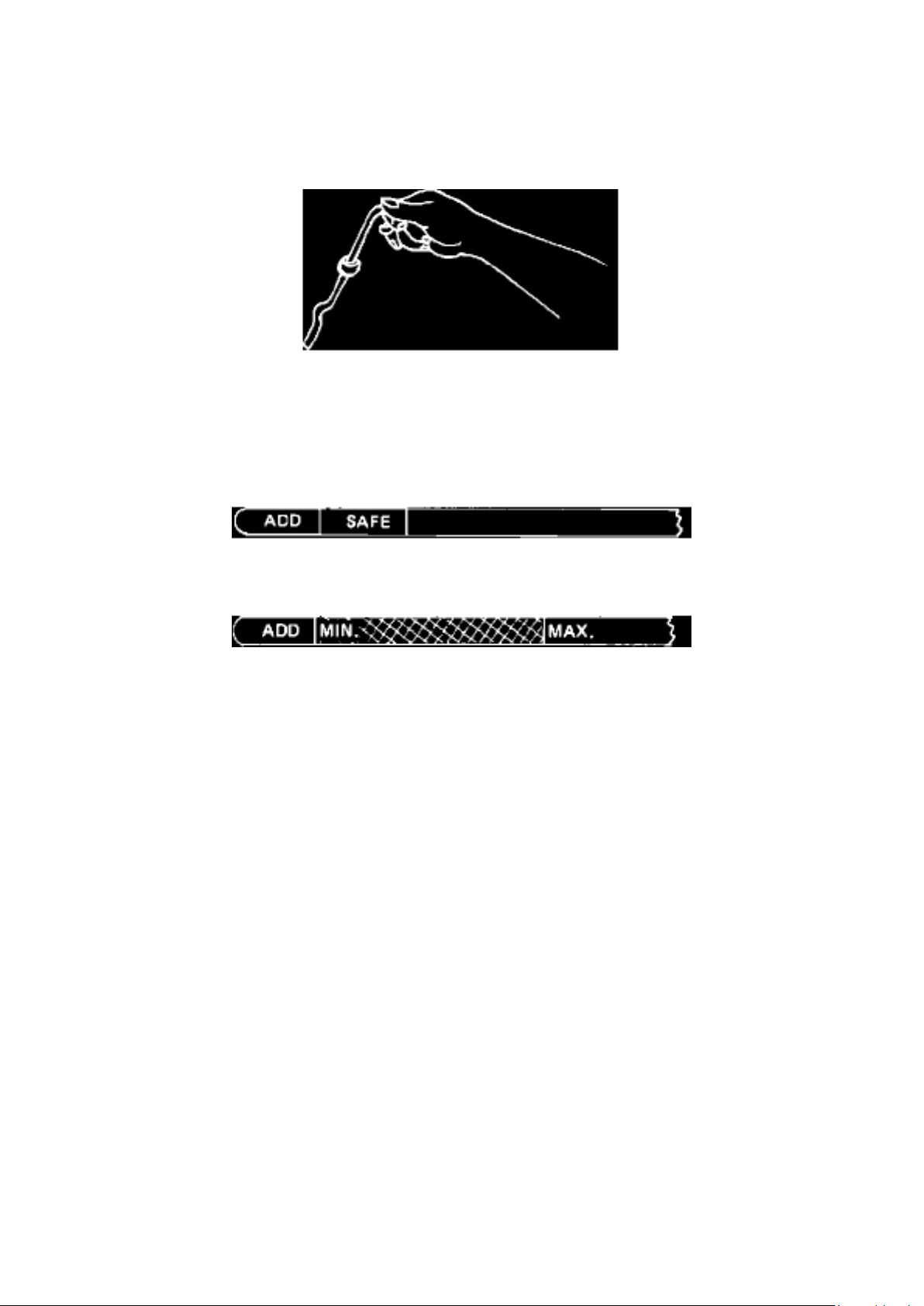
Dipsticks in Ford vehicles do not incorporate a Full mark. Instead, the dipstick will have marks
indicating a Safe range and an Add range as shown in Figure 18 or 19. When the correct amount
of oil is in the engine, the oil level indication will be in the Safe range or above the Minimum mark,
but not necessarily at the top of the Safe range or at the Maximum mark.
When the indicated oil level is in the Add range put one quart of oil in the engine. Recheck the oil
level to determine if the oil level is now in the Safe range or above the Minimum mark.
Page 45

Add and recheck oil level one quart at a time until the oil level indicator moves into the Safe range
or above the Minimum mark. Do not add additional oil to bring the level to the top of the Safe range
or to the Maximum mark since this may result in overfill and increased oil consumption. If the
accuracy of the engine oil dipstick is in doubt, it may be verified in the following manner:
^ Drain the oil and install a new filter.
^ Put in the specified amount of oil for an oil and filter change. (See owner guide)
^ Start the engine and operate a few minutes.
^ Shut off the engine and allow a few minutes for the oil to drain down.
^ Check the oil level with the dipstick.
^ If the oil level does not indicate in the Safe range or above the Minimum mark, rework or replace
the dipstick.
OTHER APPLICABLE ARTICLES: None WARRANTY STATUS: "INFORMATION ONLY"
Page 46

Ford Courier Workshop Manual (L4-2299cc (1982))
Ford Workshop Manuals > Maintenance > Fluids > Refrigerant > Component Information > Technical Service Bulletins > Air
Conditioning - Use of Correct Fluorescent Tracer Dye
Page 47

Refrigerant: Technical Service Bulletins Air Conditioning - Use of Correct Fluorescent Tracer Dye
Article No. 93-20-6
09/29/93
AIR CONDITIONING - USE OF CORRECT FLUORESCENT TRACER DYE - SERVICE TIP
FORD: 1980-93 CROWN VICTORIA 1981-93 ESCORT 1982-83 FAIRMONT 1982-88 EXP
1982-93 MUSTANG, THUNDERBIRD 1983-86 LTD 1984-93 TEMPO 1986-93 TAURUS 1988-93
FESTIVA 1989-93 PROBE
LINCOLN-MERCURY: 1980-93 GRAND MARQUIS, TOWN CAR 1981-87 LYNX 1982-83 LN7,
ZEPHYR 1982-86 CAPRI 1982-93 CONTINENTAL, COUGAR 1983-86 MARQUIS 1984-92 MARK
VII 1984-93 TOPAZ 1986-93 SABLE 1991-93 CAPRI, TRACER
LIGHT TRUCK: 1980-93 BRONCO, ECONOLINE, F-150-350 SERIES 1983-93 RANGER 1984-90
BRONCO II 1986-93 AEROSTAR 1988-93 F-47 1991-93 EXPLORER 1993 VILLAGER
ISSUE: Use of untested, unapproved fluorescent tracer dyes for A/C system leak checking may
damage the air conditioning system. Some of these materials may not be compatible with Ford A/C
systems.
ACTION: When leak-checking an R-12 A/C system with a "black light", use only Rotunda-supplied
Part No. 112-R0027, Fluoro-Lite brand dye. No other dyes have been approved by Ford Motor
Company.
NOTE: 112-R0027 DYE IS NOT COMPATIBLE WITH R-134a REFRIGERANT.
OTHER APPLICABLE ARTICLES: NONE WARRANTY STATUS: INFORMATION ONLY OASIS
CODES: 208999
Page 48

Ford Courier Workshop Manual (L4-2299cc (1982))
Ford Workshop Manuals > Maintenance > Fluids > Refrigerant > Component Information > Technical Service Bulletins > Air
Conditioning - Use of Correct Fluorescent Tracer Dye > Page 81
Page 49

Refrigerant: Technical Service Bulletins R-12 Refrigerant - Substitutes
Article No. 94-14-3
07/13/94
Air Conditioning - Use Of R-12 Refrigerant Substitutes - Service Tip
FORD: 1980-93 CROWN VICTORIA 1981-93 ESCORT 1982-83 FAIRMONT 1982-88 EXP
1982-93 MUSTANG, THUNDERBIRD 1983-86 LTD 1984-93 TEMPO 1986-93 TAURUS 1988-93
FESTIVA 1989-93 PROBE
LINCOLN-MERCURY: 1980-93 GRAND MARQUIS, TOWN CAR 1981-87 LYNX 1982-83 LN7,
ZEPHYR 1982-86 CAPRI 1982-93 CONTINENTAL, COUGAR 1983-86 MARQUIS 1984-92 MARK
VII 1984-93 TOPAZ 1986-93 SABLE 1991-93 CAPRI, TRACER
MERKUR: 1986-89 SCORPIO, XR4TI
LIGHT TRUCK: 1980-93 BRONCO, ECONOLINE, F-150-350 SERIES 1983-93 RANGER 1984-90
BRONCO II 1986-93 AEROSTAR 1988-93 F-47 1991-93 EXPLORER 1992-94 F-53 1993
VILLAGER
MEDIUM/HEAVY TRUCK: 1954-90 C SERIES 1970-94 L SERIES 1979-90 CL-9000,
CL-CLT-9000 SERIES 1980-94 F SERIES 1986-94 CARGO SERIES
This TSB is being republished in its entirety to include Heavy Truck models.
ISSUE:
A number of manufacturers are producing refrigerant products which are described as being direct
replacements for refrigerant R-12. The use of any unauthorized substitute refrigerant may severely
damage the A/C system components.
ACTION:
If service is required, use only NEW or RECYCLED refrigerant R-12.
Ford Motor Company has not tested or approved any R-12 refrigerant substitute at this time.
R-134a is approved only for systems which specify R-134a,
Page 50

Ford Courier Workshop Manual (L4-2299cc (1982))
Ford Workshop Manuals > Maintenance > Fluids > Refrigerant > Component Information > Technical Service Bulletins > Air
Conditioning - Use of Correct Fluorescent Tracer Dye > Page 82
Page 51

and is not compatible with R-12 systems.
R-22 likewise, is not compatible with R-12 systems.
CAUTION:
USING ANY UNAUTHORIZED SUBSTITUTE REFRIGERANT FOR R-12 MAY RESULT IN
SEVERE DAMAGE TO THE A/C SYSTEM COMPONENTS.
OTHER APPLICABLE ARTICLES: 91-9-7
SUPERSEDES: 93-23-11
WARRANTY STATUS: INFORMATION ONLY
OASIS CODES: 208000, 208999, 290000
Page 52

Ford Courier Workshop Manual (L4-2299cc (1982))
Ford Workshop Manuals > Maintenance > Fluids > Refrigerant > Component Information > Technical Service Bulletins >
Page 83
Page 53

Refrigerant: Specifications
Type .....................................................................................................................................................
............................................... Refrigerant 12 (R-12) Ford Part Number .............................................
........................................................................................................................................
D4AZ-19B519-A
Page 54

Ford Courier Workshop Manual (L4-2299cc (1982))
Ford Workshop Manuals > Maintenance > Fluids > Refrigerant Oil > Component Information > Specifications
Page 55

Refrigerant Oil: Specifications
Compressor ................................................................................................................... 500 viscosity
(C9AZ-19557-B or Motorcraft VN-2 or equivalent)
Page 56

Ford Courier Workshop Manual (L4-2299cc (1982))
Ford Workshop Manuals > Maintenance > Fuses and Circuit Breakers > System Information > Service Precautions
Page 57

Fuses and Circuit Breakers: Service Precautions
FUSE AND CIRCUIT BREAKER PRECAUTIONS
When replacing a blown fuse or defective circuit breaker, it is important to use only a fuse or circuit
breaker having the correct amperage rating. The use of a fuse or circuit breaker with a rating other
than indicated may result in a dangerous electrical system overload. If a properly rated fuse or
circuit breaker continues to blow or trip, it indicates a problem in the circuit that must be corrected.
Page 58

Ford Courier Workshop Manual (L4-2299cc (1982))
Ford Workshop Manuals > Maintenance > Service Reminder Indicators > EGR Maintenance Light > Component Information
> Service and Repair
Page 59

EGR Maintenance Light: Service and Repair
EGR Warning Switch Reset
NOTE:
After performing the necessary EGR system maintenance, the EGR warning lamp switch can be
reset. The switch is installed behind the speedometer and is reset as follows:
Procedure
1. Remove cover from switch.
2. Slide the switch knob to the opposite position and the warning lamp will go out.
Page 60
Ford Courier Workshop Manual (L4-2299cc (1982))
Ford Workshop Manuals > Engine, Cooling and Exhaust > Engine > Engine Lubrication > Engine Oil > Component
Information > Technical Service Bulletins > Engine - Oil Level Checking Procedure
Engine Oil: Technical Service Bulletins Engine - Oil Level Checking Procedure
Article No. 85-25-20
OIL DIPSTICK - ENGINE OIL LEVEL CHECKING PROCEDURE - GASOLINE ENGINES
LIGHT TRUCK 1986 AND PRIOR
MEDIUM/HEAVY TRUCK 1986 AND PRIOR
Figure 17 - Dipstick
To correctly check the engine oil level, the vehicle must be parked on a level surface. Allow a few
minutes after shutting the engine off for oil to drain down before checking. For consistent oil level
readings, insert the dipstick with the loop of the handle as shown in Figure 17.
Figure 18 - Dipstick - Calibration
Figure 19 - Dipstick - Calibration
Dipsticks in Ford vehicles do not incorporate a Full mark. Instead, the dipstick will have marks
indicating a Safe range and an Add range as shown in Figure 18 or 19. When the correct amount
of oil is in the engine, the oil level indication will be in the Safe range or above the Minimum mark,
but not necessarily at the top of the Safe range or at the Maximum mark.
When the indicated oil level is in the Add range put one quart of oil in the engine. Recheck the oil
level to determine if the oil level is now in the Safe range or above the Minimum mark.
Page 61

Add and recheck oil level one quart at a time until the oil level indicator moves into the Safe range
or above the Minimum mark. Do not add additional oil to bring the level to the top of the Safe range
or to the Maximum mark since this may result in overfill and increased oil consumption. If the
accuracy of the engine oil dipstick is in doubt, it may be verified in the following manner:
^ Drain the oil and install a new filter.
^ Put in the specified amount of oil for an oil and filter change. (See owner guide)
^ Start the engine and operate a few minutes.
^ Shut off the engine and allow a few minutes for the oil to drain down.
^ Check the oil level with the dipstick.
^ If the oil level does not indicate in the Safe range or above the Minimum mark, rework or replace
the dipstick.
OTHER APPLICABLE ARTICLES: None WARRANTY STATUS: "INFORMATION ONLY"
Page 62

Ford Courier Workshop Manual (L4-2299cc (1982))
Ford Workshop Manuals > Engine, Cooling and Exhaust > Engine > Seals and Gaskets, Engine > Crankshaft Main Bearing
Seal > Component Information > Technical Service Bulletins > Crankshaft Seal - Leaks, Air Pressure Test
Page 63

Crankshaft Main Bearing Seal: Technical Service Bulletins Crankshaft Seal - Leaks, Air Pressure
Test
Article No. 86-3-14
LEAK OIL - CRANKSHAFT SEAL - AIR PRESSURE TEST
FORD 1986 and Prior FORD, THUNDERBIRD, LTD, ESCORT, FAIRMONT, MUSTANG, EXP,
TAURUS
LINCOLN-MERCURY 1986 and Prior LINCOLN, MARK, CONTINENTAL, MERCURY, MARQUIS,
COUGAR, CAPRI, LYNX, LN7, SABLE
LIGHT TRUCK 1986 and Prior RANGER, BRONCO II, AEROSTAR, E AND F SERIES
To prevent repeat servicing on engines suspected of oil leakage at the crankshaft seal, determine if
the leak is actually from the seal or from another source such as the rear pan seal or galley plugs.
The one-piece rear crankshaft seal is released for all passenger car and light truck engines and
has proven to be more reliable than the rope or split lip design formerly used.
Performing the oil leak air pressure check outlined in all Car and Truck Powertrain Shop Manuals,
Section 21- 01 will accurately identify the location of the leak and can verify correction after
servicing before the transmission is reinstalled.
OTHER APPLICABLE ARTICLES: 80-15-5, 83-14-8 WARRANTY STATUS: "INFORMATION
ONLY"
Page 64

Ford Courier Workshop Manual (L4-2299cc (1982))
Ford Workshop Manuals > Engine, Cooling and Exhaust > Engine > Tune-up and Engine Performance Checks > Fuel
Pressure > System Information > Specifications
Page 65

Fuel Pressure: Specifications
FUEL PRESSURE
Pump Pressure ....................................................................................................................................
................................................................ 2.8 - 3.6 psi
Page 66

Ford Courier Workshop Manual (L4-2299cc (1982))
Ford Workshop Manuals > Engine, Cooling and Exhaust > Engine > Tune-up and Engine Performance Checks > Fuel Filter
> Component Information > Technical Service Bulletins > Fuel Filter - Replacement Information
Page 67

Fuel Filter: Technical Service Bulletins Fuel Filter - Replacement Information
Article No. 85-6-10
FUEL FILTER REPLACEMENT INFORMATION - ALL WITH FUEL FILTERS ATTACHED TO THE
CARBURETOR AND/OR FUEL LINE WITH A RUBBER HOSE
FORD ALL 1985 AND PRIOR
LINCOLN-MERCURY ALL 1985 AND PRIOR
LIGHT TRUCK ALL 1985 AND PRIOR
New fuel connector hoses and clamps should be used whenever a fuel filter is replaced.
Due to possible deterioration of hose materials which may result if a vehicle is fueled with gasoline
containing excessive levels of methanol or ethanol, a new fuel hose and clamps should be installed
when the fuel filter is changed. DO NOT REUSE OLD HOSES OR CLAMPS.
OTHER APPLICABLE ARTICLES: NONE WARRANTY STATUS: "INFORMATION ONLY"
Page 68

Ford Courier Workshop Manual (L4-2299cc (1982))
Ford Workshop Manuals > Engine, Cooling and Exhaust > Cooling System > Coolant > Component Information > Technical
Service Bulletins > Recycled Engine Coolant - Service Tips
Page 69

Coolant: Technical Service Bulletins Recycled Engine Coolant - Service Tips
Article No. 95-18-2
09/11/95
^ COOLANT - USE OF RECYCLED ENGINE, COOLANT - SERVICE TIP
^ COOLING SYSTEM - USE OF RECYCLED ENGINE, COOLANT - SERVICE TIP
FORD: 1980 and after CROWN VICTORIA, MUSTANG, THUNDERBIRD 1981 and after ESCORT
1982-88 EXP 1984-94 TEMPO 1986 and after TAURUS 1988-93 FESTIVA 1989 and after PROBE
1994 and after ASPIRE 1995 and after CONTOUR
LINCOLN-MERCURY: 1980 and after CONTINENTAL, COUGAR, GRAND MARQUIS, TOWN
CAR 1981-86 CAPRI 1981-87 LYNX 1984-92 MARK VII 1984-94 TOPAZ 1986 and after SABLE
1987-89 TRACER 1991-94 CAPRI 1991 and after TRACER 1993 and after MARK VIII 1995 and
after MYSTIQUE
MERKUR: 1985-89 XR4TI 1988-89 SCORPIO
LIGHT TRUCK: 1980 and after F-150-350 SERIES 1981 and after ECONOLINE 1982 and after
BRONCO 1983 and after RANGER 1984-90 BRONCO II 1986 and after AEROSTAR 1988 and
after F SUPER DUTY 1991 and after EXPLORER 1993 and after VILLAGER 1995 and after
WINDSTAR
This TSB is being republished in its entirety to include warranty information when using recycled
coolant
ISSUE: Ford Motor Company authorizes the use of recycled engine coolant that, when properly
processed and reinhibited, meets Ford specification ESE-M97B44-A. At this time, the Rotunda
Coolant Recycler (181-00003) process is the only approved coolant recycling method available
through Ford that is capable of producing recycled engine coolant that meets Ford specification
ESE-M97B44-A.
ACTION: Refer to the following Service Procedure for coolant processing and reinhibiting using
Rotunda Coolant Recycler (181-00003).
NOTE:
WHILE TESTING SHOWS THAT RECYCLED ENGINE COOLANT CAN PROVIDE ACCEPTABLE
PERFORMANCE, THE COOLANT PRODUCED FROM ROTUNDA EQUIPMENT IS INTENDED
FOR USE WITHIN DEALERSHIPS ON WARRANTY AND CUSTOMER PAY REPAIRS ONLY
AND NOT INTENDED FOR RETAIL SALE. THERE ARE REGULATORY, PACKAGING AND
LABELING CONCERNS
Page 70

Ford Courier Workshop Manual (L4-2299cc (1982))
Ford Workshop Manuals > Engine, Cooling and Exhaust > Cooling System > Coolant > Component Information > Technical
Service Bulletins > Recycled Engine Coolant - Service Tips > Page 119
Page 71

ASSOCIATED WITH THE RETAIL SALE OF CHEMICAL PRODUCTS.
CAUTION:
THE REINHIBITOR CHEMICALS PROVIDED WITH THIS EQUIPMENT ARE NOT
APPROPRIATE FOR USE ON MEDIUM/HEAVY TRUCK APPLICATIONS.
WARNING:
ROTUNDA PREMIUM COOLANT REINHIBITORS # 1 AND # 2 HAVE BEEN SPECIFICALLY
FORMULATED TO WORK WITH ROTUNDA COOLANT RECYCLER (181-00003).
USE OF ANY OTHER CHEMICAL ADDITIVES WITH THIS SYSTEM WILL VOID ALL
WARRANTIES FOR THE EQUIPMENT AND FOR THE FINAL COOLANT PRODUCT.
SERVICE PROCEDURE
DIRECTIONS FOR PROCESSING USED ENGINE COOLANT WITH ROTUNDA COOLANT
RECYCLER
1. Close the drain valve on the unit.
2. Open the fill valve.
3. Pour used engine coolant into the funnel on the side of the unit.
NOTE:
MAXIMUM CAPACITY 15 25 GALLONS (95 L).
4. Insert the outlet hoses of the recycler into clean, properly labeled containers. One (1) container
is for the outlet process water and the other container is for distilled ethylene glycol.
5. Push the "ON" switch on the front to start the operation. The unit will process 1 gallon (3.8 L) per
hour of operation and will automatically shut off when cycle is complete.
6. Add reinhibitor following the directions in this article.
7. Open the drain valve to drain the residue from the distillation vessel. Dispose of residue in
accordance with all local. state and federal regulations.
ADDING REINHIBITOR CHEMICALS
1. Process the coolant according to the directions listed in this article
2. Thoroughly mix 4 fl oz (118 ml) of Reinhibitor # 1 to each gallon of distilled ethylene glycol.
3. Thoroughly mix 4 fl oz (118 ml) of Reinhibitor # 2 to each gallon of distilled ethylene glycol.
4. Mix well.
5. Check the pH level of the coolant. The pH level must be between 9 and 11.
6. Add enough water to the concentrated coolant to produce a 50/50 mixture of coolant and water.
NOTE:
THE CONCENTRATED COOLANT MUST BE MIXED WITH WATER TO MEET THE
NECESSARY ENGINE FREEZE PROTECTION.
Page 72

7. Check the coolant freeze point of the 50% coolant solution. Freeze point should be -34°F
(-37°C).
Consult the Rotunda Coolant Recycler Manual for more detailed operating instructions. Call
1-800-ROTUNDA, 8 AM to 8 PM EST, for inquiries regarding the Rotunda Coolant Recycler and to
order the Reinhibitor (187-R0001).
PART NUMBER PART NAME
Rotunda # 187-R0001 Rotunda Premium Coolant Reinhibitor
WARRANTY CLAIMS: Dealer can claim recycled engine coolant by Ford approved process via a
warranty repair on an 1863 claim as follows:
Part Number: RECCOOL (not a valid part number, but it is recognized on an 1863 claim).
Page 73

Ford Courier Workshop Manual (L4-2299cc (1982))
Ford Workshop Manuals > Engine, Cooling and Exhaust > Cooling System > Coolant > Component Information > Technical
Service Bulletins > Recycled Engine Coolant - Service Tips > Page 120
Page 74

Quantity: Indicate the number of QUARTS of recycled coolant used.
OTHER APPLICABLE ARTICLES: NONE SUPERSEDES: 95-16-6 WARRANTY STATUS:
INFORMATION ONLY OASIS CODES: 402000
Page 75

Ford Courier Workshop Manual (L4-2299cc (1982))
Ford Workshop Manuals > Engine, Cooling and Exhaust > Cooling System > Coolant > Component Information >
Specifications > Capacity Specifications
Page 76

Coolant: Capacity Specifications
Coolant Capacity 8.8 qts
..............................................................................................................................................................
.........................................
Page 77

Ford Courier Workshop Manual (L4-2299cc (1982))
Ford Workshop Manuals > Engine, Cooling and Exhaust > Cooling System > Coolant > Component Information >
Specifications > Capacity Specifications > Page 123
Page 78

Coolant: Fluid Type Specifications
COOLING SYSTEM FLUID, PREMIUM
Ford Part No.
U.S.A (Except Oregon)
............................................................................................................................................................
E2FZ-19549-AA or -B Canada ............................................................................................................
.............................................................................................. CXC-8-B Oregon ..................................
.............................................................................................................................................................
F5FZ-19549-CC
Ford Specification ................................................................................................................................
................................................... ESE-M97B44-A
COOLING SYSTEM FLUSH
Ford Part No. .......................................................................................................................................
................................................... F1AZ-19A503-A Ford Specification .................................................
..................................................................................................................................... ESR-M14P7-A
Coolant Mixture with Water .................................................................................................................
...................................................................... 50%
Warning: Do not mix coolant types. Check the owners manual or refer to your local dealer for the
correct coolant type.
Page 79

Ford Courier Workshop Manual (L4-2299cc (1982))
Ford Workshop Manuals > Engine, Cooling and Exhaust > Cooling System > Radiator Cooling Fan > Radiator Cooling Fan
Temperature Sensor / Switch > Component Information > Specifications
Radiator Cooling Fan Temperature Sensor / Switch: Specifications Switch Torque
Switch Torque
Cooling Fan Switch 8-18 ft.lb
Page 80

Ford Courier Workshop Manual (L4-2299cc (1982))
Ford Workshop Manuals > Engine, Cooling and Exhaust > Cooling System > Engine - Coolant Temperature Sensor/Switch
> Radiator Cooling Fan Temperature Sensor / Switch > Component Information > Specifications
Radiator Cooling Fan Temperature Sensor / Switch: Specifications Switch Torque
Switch Torque
Cooling Fan Switch 8-18 ft.lb
Page 81
Ford Courier Workshop Manual (L4-2299cc (1982))
Ford Workshop Manuals > Engine, Cooling and Exhaust > Cooling System > Heater Core > Component Information >
Technical Service Bulletins > Heater Core - Leakage Diagnostic Tips
Heater Core: Technical Service Bulletins Heater Core - Leakage Diagnostic Tips
Article No. 85-8-2
HEATER CORE - LEAK - DIAGNOSTIC TIPS
FORD ALL
LINCOLN-MERCURY ALL
LIGHT TRUCK ALL
Good heater cores are being returned through the parts return system coded as leaking.
Complaints of leaking may be caused by an inadequate seal between the heater hose and the
heater core tubes allowing coolant to follow the tube to the heater core, leak into the passenger
compartment and appear as a leaking heater core.
When diagnosing a suspect heater core leak, inspect the hose to heater core tube attachment to
assure the connection is not leaking. If a leaking connection is found, correct the leak. If the
connection appears not to be leaking, leak test the heater core before removing it from the vehicle
using the following procedure:
HEATER CORE LEAK TEST
Pressure Test 1.
Drain the coolant from the cooling system.
2. Disconnect the heater hoses from the heater core tubes.
Page 82

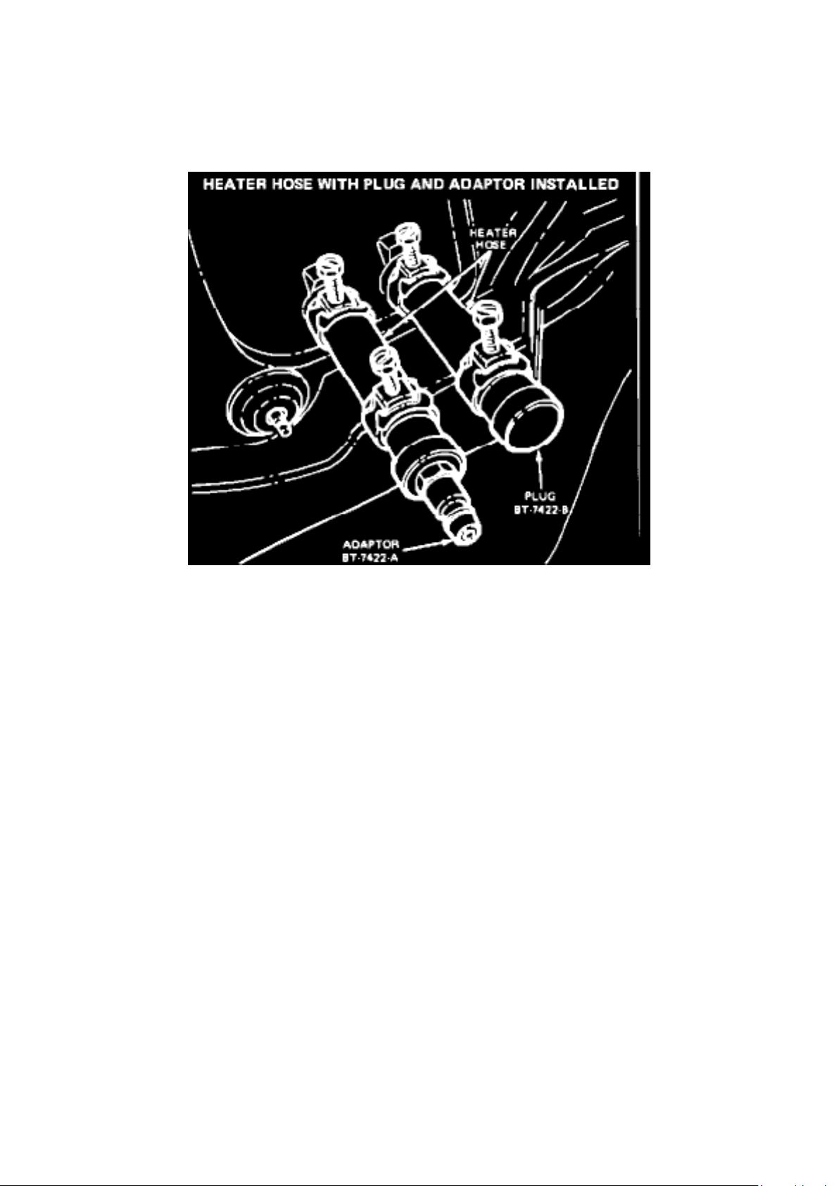
3. Install a short piece of heater hose (approximately 4 inches long) on each heater core tube.
Figure 1
4. Fill the heater core and hoses with water and install plug BT-7422-B and adapter BT-7422-A
from Rotunda model 021-00012 or equivalent in the hose ends (Figure 1). Secure the hoses, plug
and adapter with hose clamps.
Page 83
Ford Courier Workshop Manual (L4-2299cc (1982))
Ford Workshop Manuals > Engine, Cooling and Exhaust > Cooling System > Heater Core > Component Information >
Technical Service Bulletins > Heater Core - Leakage Diagnostic Tips > Page 136
Page 84

Figure 2
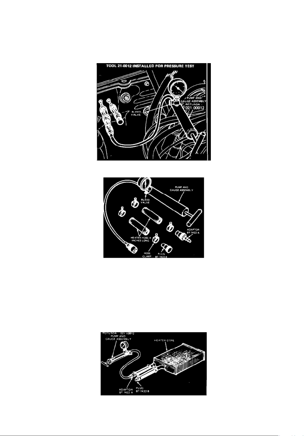
Figure 3 - TOOL 021-00012 WITH HEATER HOSE AND CLAMPS
5. Attach the pump and gauge assembly Rotunda model 021-00012 or equivalent to the adapter
(Figure 2). Close the bleed valve at the base of the gauge and pump 30 psi of air pressure into the
heater core (Figure 3).
6. Observe the pressure gauge for a minimum of three minutes. The pressure should not drop.
7. If the pressure does not drop, no leaks are indicated.
8. If the pressure drops, check the hose connections to the core tubes for leaks. If the hoses do not
leak, remove the heater core from the vehicle and perform the bench test.
Bench Test 1.
Drain all coolant from the heater core.
Figure 4 - HEATER CORE BENCH TEST
2. Connect the 4-inch test hoses with plug and adapter to the core tubes. Then connect the air
pump and gauge assembly to the adapter (Figure 4).
3. Apply 30 psi of air pressure to the heater core with Rotunda model 021-00012 or equivalent, and
submerge the core in water.
4. If a leak is observed, service or replace the heater core as necessary.
Page 85

Ford Courier Workshop Manual (L4-2299cc (1982))
Ford Workshop Manuals > Engine, Cooling and Exhaust > Cooling System > Heater Core > Component Information >
Technical Service Bulletins > Heater Core - Leakage Diagnostic Tips > Page 137
Page 86

OTHER APPLICABLE ARTICLES: NONE WARRANTY STATUS: "INFORMATION ONLY"
Page 87

Ford Courier Workshop Manual (L4-2299cc (1982))
Ford Workshop Manuals > Engine, Cooling and Exhaust > Cooling System > Sensors and Switches - Cooling System >
Engine - Coolant Temperature Sensor/Switch > Radiator Cooling Fan Temperature Sensor / Switch > Component
Information > Specifications
Radiator Cooling Fan Temperature Sensor / Switch: Specifications Switch Torque
Switch Torque
Cooling Fan Switch 8-18 ft.lb
Page 88

Ford Courier Workshop Manual (L4-2299cc (1982))
Ford Workshop Manuals > Engine, Cooling and Exhaust > Exhaust System > Catalytic Converter > Component Information
> Description and Operation
Page 89

Catalytic Converter: Description and Operation
Some 1976-82 vehicles use a catalytic converter to reduce hydrocarbon and carbon monoxide
exhaust emission levels. These vehicles are also equipped with a catalyst warning system. This
system is comprised of a thermo sensor on the catalytic converter, monitoring converter
temperature, and a warning lamp on the instrument panel which illuminates when the thermo
sensor detects converter temperatures over 1742°F.
Page 90
Ford Courier Workshop Manual (L4-2299cc (1982))
Ford Workshop Manuals > Engine, Cooling and Exhaust > Exhaust System > Catalytic Converter > Component Information
> Description and Operation > Page 147
Catalytic Converter: Testing and Inspection
Warning System Test
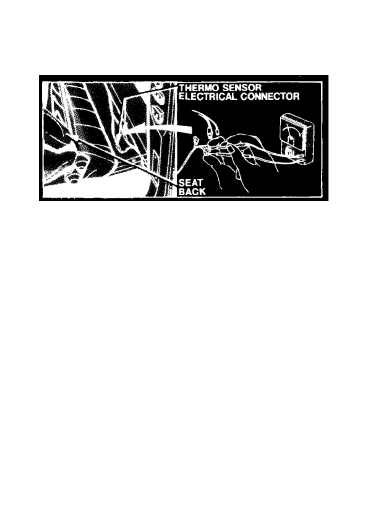
1. Turn ignition switch to "On" position. The warning lamp should illuminate, indicating that the bulb
and electrical wiring are satisfactory. If lamp
does not light, check bulb.
2. Start engine and if the system is satisfactory, the warning lamp should go out. If not, stop engine
and tilt the seatback forward.
Fig. 31 - Catalyst Warning System Test
3. Disconnect the catalytic converter thermo sensor electrical connectors, Fig. 31.
4. With an ohmmeter, check the circuit on the thermo sensor side of the wiring for continuity, Fig.
31. Replace the thermo sensor if the reading
indicates no continuity.
Page 91

Ford Courier Workshop Manual (L4-2299cc (1982))
Ford Workshop Manuals > Engine, Cooling and Exhaust > Exhaust System > Muffler > Component Information > Technical
Service Bulletins > Muffler - Unnecessary Replacement
Page 92

Muffler: Technical Service Bulletins Muffler - Unnecessary Replacement
Article No. 83-11-11
EXHAUST - MUFFLER - POWER LOW - UNNECESSARY MUFFLER REPLACEMENT
LIGHT TRUCKS 1982 AND LATER LIGHT TRUCKS
Mufflers are being replaced on leaded fuel vehicles in an effort to resolve concerns of "lack of
power" or poor performance", apparently in the belief that a plugged muffler is the cause. Although
plugging with lead deposits was possible on certain models prior to the 1982 Model Year, muffler
modifications incorporated on 1982 and later models make this an unlikely cause of the concern.
Thus, replacing mufflers on the newer model vehicles normally will not satisfy the customer. Prior
to replacing any muffler believed to be restricted, a vacuum check as described in Section 26-01 of
the Light Truck Shop Manual should be performed.
OTHER APPLICABLE ARTICLES: None WARRANTY STATUS: "INFORMATION ONLY"
Page 93
Ford Courier Workshop Manual (L4-2299cc (1982))
Ford Workshop Manuals > Powertrain Management > Relays and Modules - Powertrain Management > Relays and
Modules - Ignition System > Spark Control Relay > Component Information > Description and Operation
Spark Control Relay: Description and Operation
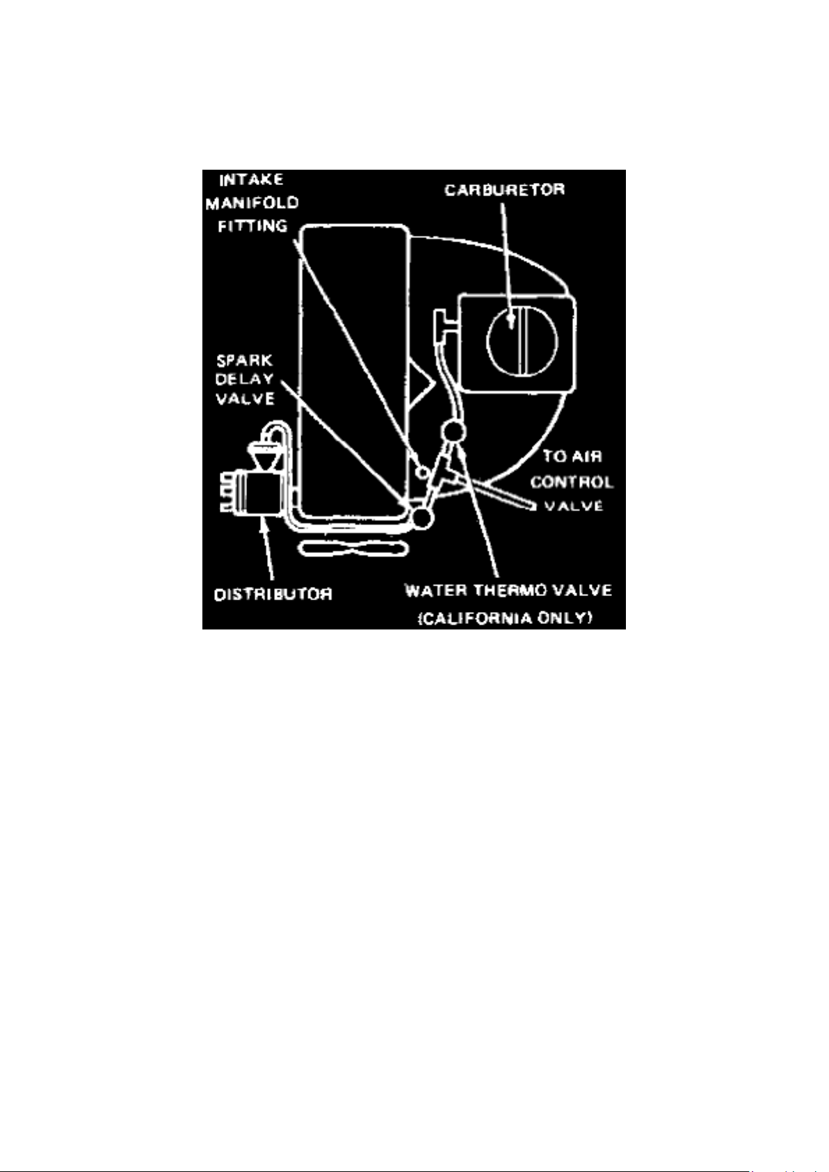
Fig. 37 - Spark Timing Control System
This system, Fig. 37, used on 1977-78 1.8 liter, 1979-82 2.0 liter and 1981-82 2.3 liter California
with manual transmission models reduces exhaust emissions by delaying vacuum to the distributor
vacuum advance unit during vehicle acceleration.
The system consists of a vacuum delay valve installed in the vacuum line between the carburetor
and distributor on 1.8 liter and 2.0 liter engines except California, or between the water thermo
valve and distributor on 2.0 liter California engines. On 2.3 liter engines, the system consists of a
spark delay valve (manual transmission equipped models) and a distributor solenoid valve installed
in the vacuum line between the intake manifold and distributor. The distributor solenoid valve is
controlled by a timer and water thermo switch (also a distributor water thermo switch on vehicles
with automatic transmission).
The spark delay valve has an internal restrictor to slow air flow in one direction and a check valve
which allows free air flow in the opposite direction.
On 1979-82 California models, distributor vacuum advance is restricted by the water thermo valve
which detects engine coolant temperature. This helps to warm up the catalytic converter.
Page 94
Ford Courier Workshop Manual (L4-2299cc (1982))
Ford Workshop Manuals > Powertrain Management > Relays and Modules - Powertrain Management > Relays and
Modules - Ignition System > Spark Control Relay > Component Information > Testing and Inspection > Spark Delay Valve
Page 95

Spark Control Relay: Testing and Inspection Spark Delay Valve
Spark Delay Valve, 1977-80, 1980-82 exc. Calif.
1. Remove air cleaner and disconnect vacuum line from distributor.
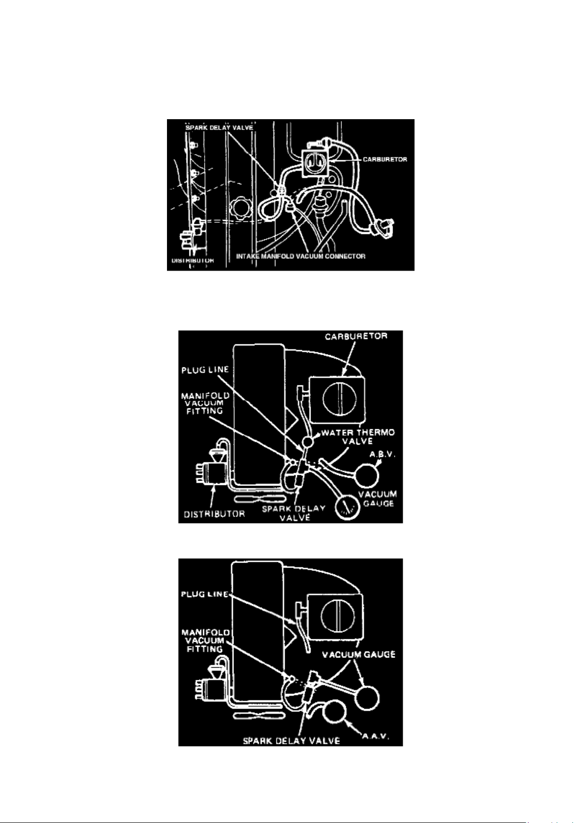
Fig. 38 - Spark Delay Valve Test
2. On 1977-78, disconnect vacuum control line at intake manifold fitting and install distributor
vacuum line to intake manifold fitting, Fig. 38.
Fig. 39 - Spark Delay Valve Test
Fig. 40 - Spark Delay Valve Test
3. On 1979-82, disconnect air bypass line on California models, Figs. 39 and 40, or air
anti-afterburn valve on except California models and connect
distributor vacuum line disconnected previously to intake manifold fitting.
Page 96
Ford Courier Workshop Manual (L4-2299cc (1982))
Ford Workshop Manuals > Powertrain Management > Relays and Modules - Powertrain Management > Relays and
Modules - Ignition System > Spark Control Relay > Component Information > Testing and Inspection > Spark Delay Valve >
Page 160
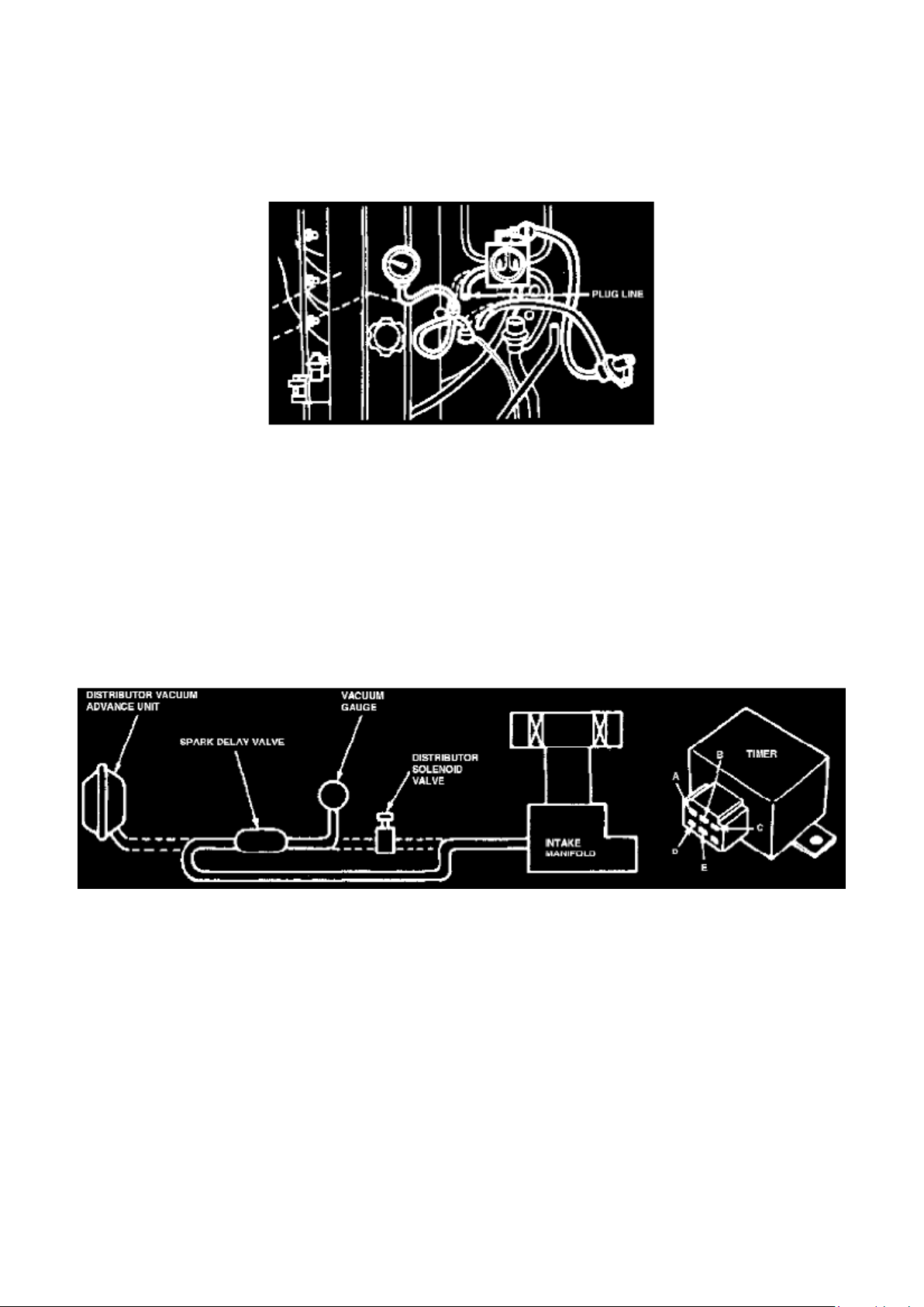
Fig. 41 - Spark Delay Valve Test
4. Remove vacuum line from carburetor side of vacuum delay valve, then plug in and connect a
vacuum gauge to vacuum delay valve, Figs. 39, 40
and 41.
5. Start engine and allow to idle.
6. Disconnect vacuum line from intake manifold fitting.
NOTE:The time required for vacuum reading to drop to 11.8 inches Hg. If amount of time is not
within 4-6 seconds, replace valve.
Spark Delay Valve, 1981-82 2.3L Calif, 1982 2.OL Calif.
Page 97

Fig. 42 - Spark Delay Valve Test
1. Disconnect vacuum sensing tube from spark delay valve at distributor solenoid and connect a
vacuum gauge to tube.
NOTE: On 1982 vehicles, add a 30mm vacuum reservoir between spark delay valve and vacuum
gauge.
2. Disconnect vacuum sensing tube from spark delay valve at distributor vacuum advance unit and
connect tube to intake manifold.
3. Start engine and note vacuum reading at idle.
4. Disconnect tube from intake manifold and check time required for vacuum reading to drop
decrease by 11.8 inches Hg. vacuum. Time required
should be 5 ± 1 seconds.
Page 98

Ford Courier Workshop Manual (L4-2299cc (1982))
Ford Workshop Manuals > Powertrain Management > Relays and Modules - Powertrain Management > Relays and
Modules - Ignition System > Spark Control Relay > Component Information > Testing and Inspection > Spark Delay Valve >
Page 161
Page 99

Spark Control Relay: Testing and Inspection Distributor Solenoid Valve
Page 100

1. Start engine and allow to idle.
2. Separate connector at distributor solenoid valve and apply battery voltage to the two terminals to
energize the solenoid.
3. Disconnect vacuum sensing tube from distributor solenoid valve at distributor vacuum advance.
4. Disconnect battery power from solenoid. Solenoid is functioning properly if vacuum is drawn into
vacuum sensing tube when battery is
disconnected.
 Loading...