

Ford ST3093-A, ST257-A, ST2834-A, 2011 Mustang Instructions Manual

419-11-i
Electronic Compass 419-11-i
SECTION 419-11 Electronic Compass
CONTENTS PAGE
DIAGNOSIS AND TESTING
Electronic Compass ............................................................................................................................................................ 419-11-2
Principles of Operation ................................................................................................................................................. 419-11-2
Inspection and Verification ........................................................................................................................................... 419-11-2
DTC Charts ................................................................................................................................................................... 419-11-3
Symptom Chart ............................................................................................................................................................. 419-11-3
Pinpoint Tests ............................................................................................................................................................... 419-11-3
2011 Mustang, 2/2011
419-11-2
DIAGNOSIS AND TESTING
Electronic Compass
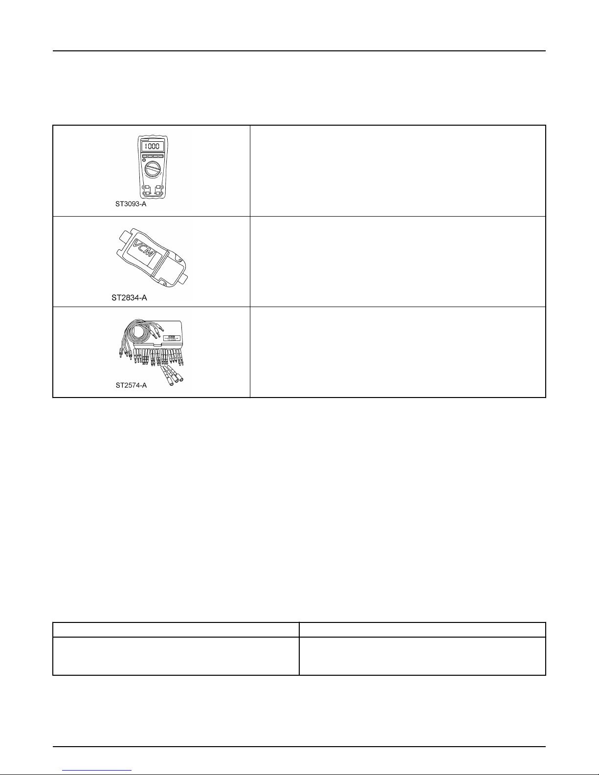
Special Tool(s)
Electronic Compass 419-11-2
Fluke 77-IV Digital Multimeter
FLU77-4 or equivalent
Vehicle Communication Module (VCM) and Integrated Diagnostic System (IDS) software
with appropriate hardware, or equivalent scan tool
Flex Probe Kit
105-R025D or equivalent
Principles of Operation
NOTE:
The Smart Junction Box (SJB) is also known as the Generic Electronic Module (GEM).
NOTE:
This procedure is only applicable to vehicles without navigation. For vehicles with navigation, refer to Section 415-00.
The compass display (located in the Front Display Interface Module (FDIM)) receives battery voltage from the SJB. The compass module (integral to the
auto-dimming interior mirror) provides hardwired vehicle directional inputs to the Instrument Panel Cluster (IPC), which sends the compass information to
the FDIM over the Medium Speed Controller Area Network (MS-CAN). The compass is capable of self-calibrating. This decreases the need to manually set
the compass. If the compass is displaying a heading (and not displaying the C or CAL indicator), the compass is in auto-calibration mode. In this mode, the
compass automatically calibrates for changes in vehicle magnetics over the life of the vehicle. This auto-calibration mode makes sure the compass heading is
always accurate. If the compass displays the C or CAL indicator for an extended period of time (longer than 5 seconds), this indicates the compass has been
placed in the manual calibration mode and therefore, requires manual calibration.
Inspection and Verification
1. Verify the customer concern.
2. Visually inspect for obvious signs of mechanical or electrical damage.
Visual Inspection Chart
Mechanical Electrical
• Compass module (integral to the auto-dimming interior mirror)
• Front Display Interface Module (FDIM)
3. If an obvious cause for an observed or reported concern is found, correct the cause (if possible) before proceeding to the next step.
4. NOTE:
Make sure to use the latest scan tool software release.
• Smart Junction Box (SJB) fuse(s):
— 14 (10A) (FDIM)
— 41 (15A) (compass module)
• Wiring, terminals or connectors
If the cause is not visually evident, connect the scan tool to the Data Link Connector (DLC).
2011 Mustang, 2/2011

419-11-3
Electronic Compass 419-11-3
DIAGNOSIS AND TESTING (Continued)
5. NOTE:
The Vehicle Communication Module (VCM) LED prove-out confirms power and ground from the DLC are provided to the VCM.
If the scan tool does not communicate with the VCM:
• Check the VCM connection to the vehicle.
• Check the scan tool connection to the VCM.
• Refer to Section 418-00, No Power To The Scan Tool, to diagnose no power to the scan tool.
6. If the scan tool does not communicate with the vehicle:
• Verify the ignition key is in the ON position.
• Verify the scan tool operation with a known good vehicle.
• Refer to Section 418-00 to diagnose no response from the PCM.
7. Carry out the network test.
If the scan tool responds with no communication for one or more modules, refer to Section 418-00.
•
If the network test passes, retrieve and record the continuous memory DTCs.
•
8. Clear the continuous DTCs and carry out the self-test diagnostics for the FDIM and the Instrument Panel Cluster (IPC).
9. If the DTCs retrieved are related to the concern, go to DTC Charts. For all other DTCs, refer to the Diagnostic Trouble Code (DTC) Chart in Section
419-10.
10. If no DTCs related to the concern are retrieved, GO to Symptom Chart.
DTC Charts
NOTE:
This module utilizes a 5-character DTC followed by a 2-character failure-type code. The failure-type code provides information about specific fault
conditions such as opens, or shorts to ground. Continuous memory DTCs have an additional 2-character DTC status code suffix to assist in determining DTC
history.
Instrument Panel Cluster (IPC) DTC Chart
DTC Description Action
U0161:87 Lost Communication With Compass Module: Missing Message GO to Pinpoint Test A.
U0161:92 Lost Communication With Compass Module: Performance or
Incorrect Operation
All other DTCs — REFER to the Diagnostic Trouble Code (DTC) Chart in Section
GO to Pinpoint Test A.
419-10.
Symptom Chart
Symptom Chart
Condition Possible Sources Action
The compass is inoperative
•
The compass is inaccurate
•
Fuse(s)
•
Wiring, terminals or connectors
•
Compass module (integral to the auto-
•
dimming interior mirror)
Front Display Interface Module (FDIM)
•
Instrument Panel Cluster (IPC)
•
Compass zone setting
•
Compass calibration
•
Compass module (integral to the auto-
•
dimming interior mirror)
GO to Pinpoint Test A.
•
GO to Pinpoint Test B.
•
Pinpoint Tests
Pinpoint Test A: The Compass Is Inoperative
Refer to Wiring Diagrams Cell 124 Power Mirrors for schematic and connector information.
Normal Operation
2011 Mustang, 2/2011
 Loading...