

Ford 2010 Econoline Owner's Manual

Table of Contents
Introduction
Instrument Cluster
Driving
Roadside Emergencies
Cleaning
Maintenance and Specifications
Scheduled Maintenance: General Information
Scheduled Maintenance: E-Series
Scheduled Maintenance: F-Super Duty
Scheduled Maintenance: Special Information
2
7
11
24
30
33
61
67
84
101
All rights reserved. Reproduction by any means, electronic or mechanical
including photocopying, recording or by any information storage and retrieval
system or translation in whole or part is not permitted without written
authorization from Ford Motor Company. Ford may change the contents without
notice and without incurring obligation.
2010 Econoline (eco)
Supplement (supplement), 1st Printing
USA (fus)
Copyright © 2009 Ford Motor Company
1

Introduction
CALIFORNIA Proposition 65 Warning
WARNING: Engine exhaust, some of its constituents, and
certain vehicle components contain or emit chemicals known to
the State of California to cause cancer and birth defects or other
reproductive harm. In addition, certain fluids contained in vehicles and
certain products of component wear contain or emit chemicals known
to the State of California to cause cancer and birth defects or other
reproductive harm.
POWER STROKE DIESEL ENGINE
Your new diesel engine will feel, drive and function somewhat differently
than a gasoline engine. Therefore it is very important that you read and
thoroughly familiarize yourself and others operating the vehicle with this
guide. A special procedure for turning off the diesel engine is in
the Driving chapter. It is important to read and understand this
material in order to maintain the best service life for your
engine.
This guide will acquaint you with the Power Stroke diesel engine. It
provides recommendations on engine care and operating procedures. For
complete vehicle information, also refer to the Owner’s Guide included
with the vehicle. It also describes equipment and gives specifications for
equipment that was in effect when this guide was approved for printing,
and should be considered a permanent part of the vehicle.
Some aftermarket products may cause severe engine/transmission
and/or exhaust system damage; refer to the warranty information in
the Customer Information Guide for more information.Your vehicle’s
Powertrain Control Systems can detect and store information
about vehicle modifications that increase horsepower and torque
output such as whether or not performance-enhancing powertrain
components commonly referred to as “performance chips” have
been used. This information cannot be erased and will stay in the
system’s memory even if the modification is removed. The
Information can be retrieved by Ford Motor Company, Ford of
Canada, and service and repair facilities when servicing your
vehicle. This information may be used to determine if repairs will
be covered by warranty.
Ford may discontinue models or change specifications without any notice
and without incurring obligations.
2
2010 Econoline (eco)
Supplement (supplement), 1st Printing
USA (fus)

Introduction
Important notice
Ford vehicles are suitable for producing ambulances only if equipped
with the Ford ambulance preparation package. In addition, Ford urges
ambulance manufacturers to follow the recommendation of the Ford
Incomplete Vehicle Manual, Ford Truck Body Builder’s Layout Book
(and pertinent supplements) and the Qualified Vehicle Modifiers
Guidelines. Using a Ford vehicle without the Ford ambulance
preparation package to produce an ambulance voids the Ford warranty
and could result in elevated underbody temperatures, fuel
overpressurization and the risk of fuel expulsion and fires. To determine
whether the vehicle is equipped with the Ford ambulance preparation
package, inspect the information plate on the driver’s side door pillar.
Contact the manufacturer of your vehicle to determine whether the
ambulance manufacturer’s followed Ford’s recommendations.
WARNINGS
Throughout this guide, you will find warnings identified by the
symbol
risk of personal injury.
NEW VEHICLE BREAK-IN
Your vehicle does not need an extensive break-in. Try not to drive
continuously at the same speed for the first 1,000 miles (1,600 km) of
new vehicle operation. Vary your speed to allow parts to adjust
themselves to other parts.
Drive your new vehicle at least 500 miles (800 km) before towing a
trailer. Make sure you use the specified engine oil by checking the engine
oil specification chart under Engine oil in the Maintenance and
Specifications chapter.
Do not add friction modifier compounds or special break-in oils during
the first few thousand miles (kilometers) of operation, since these
additives may prevent piston ring seating. See Engine oil in the
Maintenance and Specifications chapter of this supplement for more
information on oil usage.
. Warnings remind you to be especially careful to reduce the
DIESEL ENGINE INFORMATION
The Diesel engine fuel system consists of:
• On E-Series vehicles (6.0L engine), a Diesel Fuel Conditioner
Module (DFCM) mounted on the driver-side frame rail next to the
transmission
2010 Econoline (eco)
Supplement (supplement), 1st Printing
USA (fus)
3
Introduction
• On F-Super Duty vehicles (6.4L engine), a frame-mounted
Horizontal Fuel Conditioner Module (HFCM)
• an engine-mounted secondary fuel filter
• a unit injector for each cylinder
The FCM/HFCM acts as a primary fuel filter/water separator which
removes both water and impurities from the fuel. The engine mounted
filter filters finer impurities from the diesel fuel. The engine-mounted
fuel filter and the FCM/HFCM filter should be changed at the
recommended service interval. Refer to the scheduled maintenance
information in this supplement for more information.
F-Super Duty
E-Series
The FCM/HFCM should be drained at regular intervals or when the
WATER IN FUEL light illuminates in the instrument cluster.
The fuel injectors are located in the center of the combustion chambers
in the cylinder head between the rocker arm assemblies. The glow plug
system and fuel injection system are controlled through the Powertrain
Control Module (PCM) and Fuel Injection Control Module (FICM) (6.0L
engine only).
Fuel is drawn from the fuel tank by a frame-mounted electric fuel pump.
The fuel pump provides pressurized fuel to the engine and is
electronically controlled by the fuel pump PCM relay. The fuel pump
contains a pressure relief valve for overpressure protection in the event
of restricted flow.
Engine protection mode
Ford diesel engines are equipped with engine protection and emission
control systems. These systems monitor critical temperatures and
pressures, and modify engine operation accordingly. These features are
intended to modify engine performance characteristics. If these modified
engine performance characteristics persist for an extended period or the
service engine soon
power/electronic throttle control light
from your authorized dealer.
4
2010 Econoline (eco)
Supplement (supplement), 1st Printing
USA (fus)
or powertrain malfunction/reduced
is illuminated, seek service

Introduction
Lubrication system
Extended oil change intervals can negatively affect engine performance,
fuel economy and engine life. Refer to the engine oil specification chart
located under Engine oil specifications in the Maintenance and
Specifications chapter of this supplement.
On E-Series vehicles (6.0L engine), it is important to change the
engine oil at the recommended service intervals because oil viscosity is
important in maintaining the oil pressure required to actuate the fuel
injectors.
On F-Super Duty vehicles (6.4L engine), it is important to change
the engine oil at the recommended service intervals to maintain oil
viscosity with the addition of the diesel particulate filter (DPF).
Fast start glow plug system
The glow plug system consists of:
• eight glow plugs
• the glow plug control module (GPCM)
• engine oil temperature (EOT) sensor
• barometric pressure (BARO) sensor
The glow plug system is
electronically controlled by the
PCM. The GPCM energizes the glow
plugs immediately after the ignition
is placed in the ON position, then determines how long the glow plugs
will be on according to the EOT and BARO sensors. The required time
for the glow plugs to be energized decreases as the engine oil
temperature and barometric pressure increase.
Engine cooling system
The engine cooling system contains an engine oil cooler and an Exhaust
Gas Recirculation (EGR) cooler. The oil cooler’s function is to regulate
engine oil temperature. The EGR cooler function is to cool exhaust gases
before they are circulated back through the engine to reduce emissions.
Vehicles with diesel engines typically are used to carry heavy loads and
accumulate mileage rapidly. These two factors may cause the additives in
the coolant to “wear out” in a shorter time. Refer to the Special
Operating Conditions section for more information about coolant
additives and coolant change intervals. Operating the engine with
insufficient coolant and/or coolant additive can cause severe engine
damage.
2010 Econoline (eco)
Supplement (supplement), 1st Printing
USA (fus)
5

Introduction
To determine if a coolant additive recharge is required, check the nitrite
strength of the coolant using the coolant nitrate test strip kit (Acustrip
3-way Antifreeze Test Strip). If the nitrite strength is above 800 ppm no
action is required. If the nitrite strength is between 800 ppm to 300 ppm
add 32 fl. oz. (946 ml) of engine coolant additive, Motorcraft VC-8 or
equivalent. If the nitrite strength is below 300 ppm, flush & refill the
cooling system.
Fuel and turbocharger cooling system (F-Super Duty only)
The fuel and turbocharger cooling system contains a cooler which is
mounted on the turbo interstage U-tube on the left side of the engine.
The cooler’s function is to regulate engine fuel temperature and cool the
electronics that support the turbocharger. You may hear the auxiliary
coolant pump running up to 10 minutes after the ignition is turned off in
hot weather or if you are towing heavy loads. This is to control the
temperature of the turbocharger.
Engine governed speed
The engine governor is controlled by the PCM. The PCM controls fuel
input to limit maximum engine speed. It will not, however, prevent
engine overspeeding resulting from downshifting at high vehicle speed or
by descending steep grades at too high a vehicle speed for the selected
transmission gear.
If your vehicle is equipped with a manual transmission, refer to
Manual transmission shift speeds in the Driving chapter of your
Owner’s Guide for maximum vehicle shift speeds in various gears. Do
not exceed 4,000 rpm. Maximum engine governed speed is 3,700 rpm.
Excessive rpm can only be achieved by manually downshifting at too
high of a vehicle speed.
Operating the engine beyond the governed speed can cause
severe engine damage.
Speed control (F-Super Duty)
If vehicle speed goes outside a predetermined range from the set speed,
the RES (Resume) function will not reset vehicle speed. Vehicle speed
will need to be reset with the SET +/- button after reaching desired
speed using accelerator pedal.
6
2010 Econoline (eco)
Supplement (supplement), 1st Printing
USA (fus)
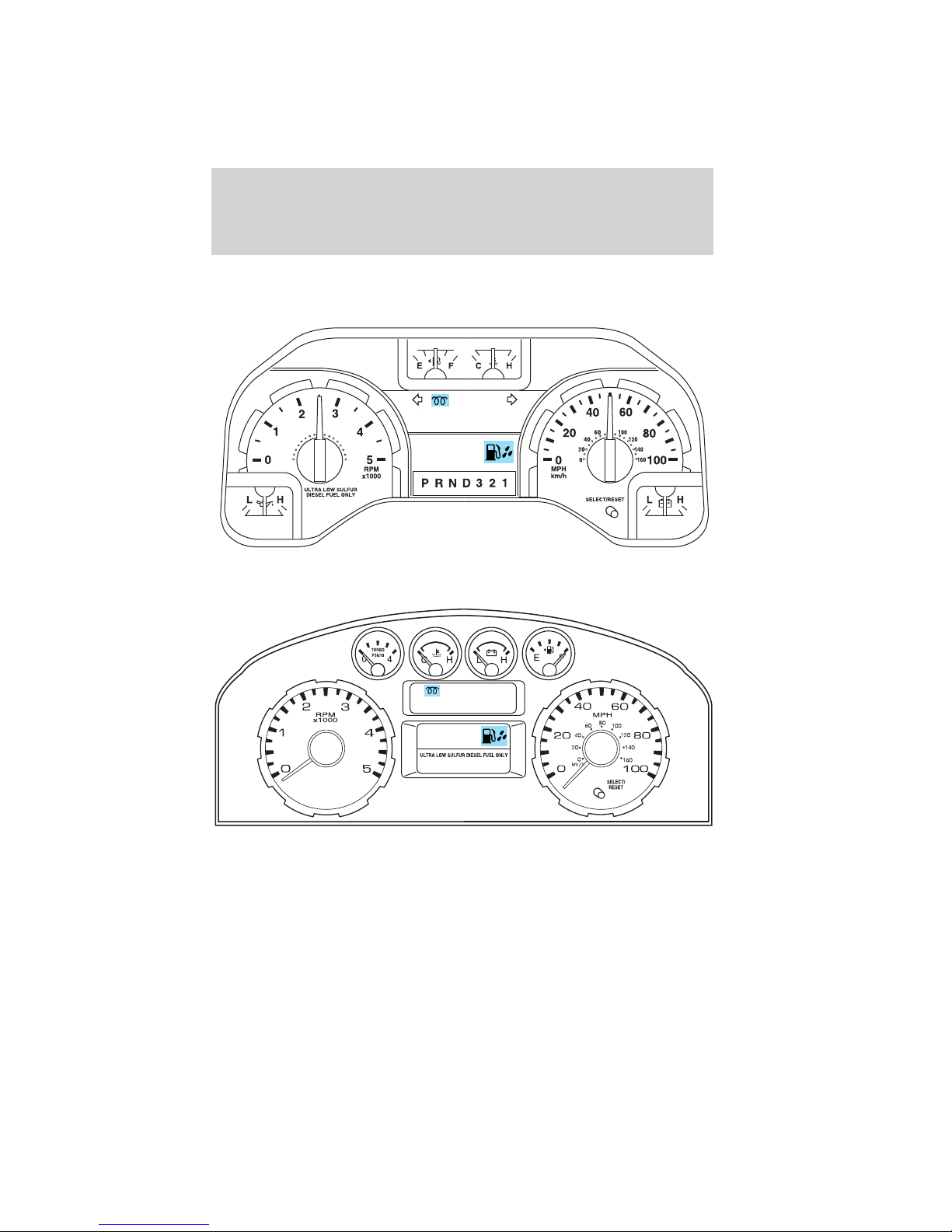
WARNING LIGHTS
E-Series
F-Super Duty w/manual transmission
Instrument Cluster
2010 Econoline (eco)
Supplement (supplement), 1st Printing
USA (fus)
7
Instrument Cluster
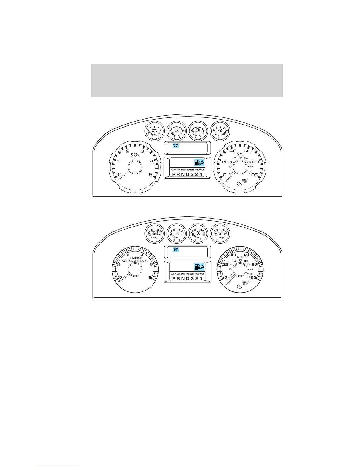
F-Super Duty w/automatic transmission
Harley-Davidson
Note: Some warning lights are reconfigurable telltale (RTT) indicator
lights and will illuminate in the message center display and function the
same as the warning light.
8
2010 Econoline (eco)
Supplement (supplement), 1st Printing
USA (fus)
Instrument Cluster
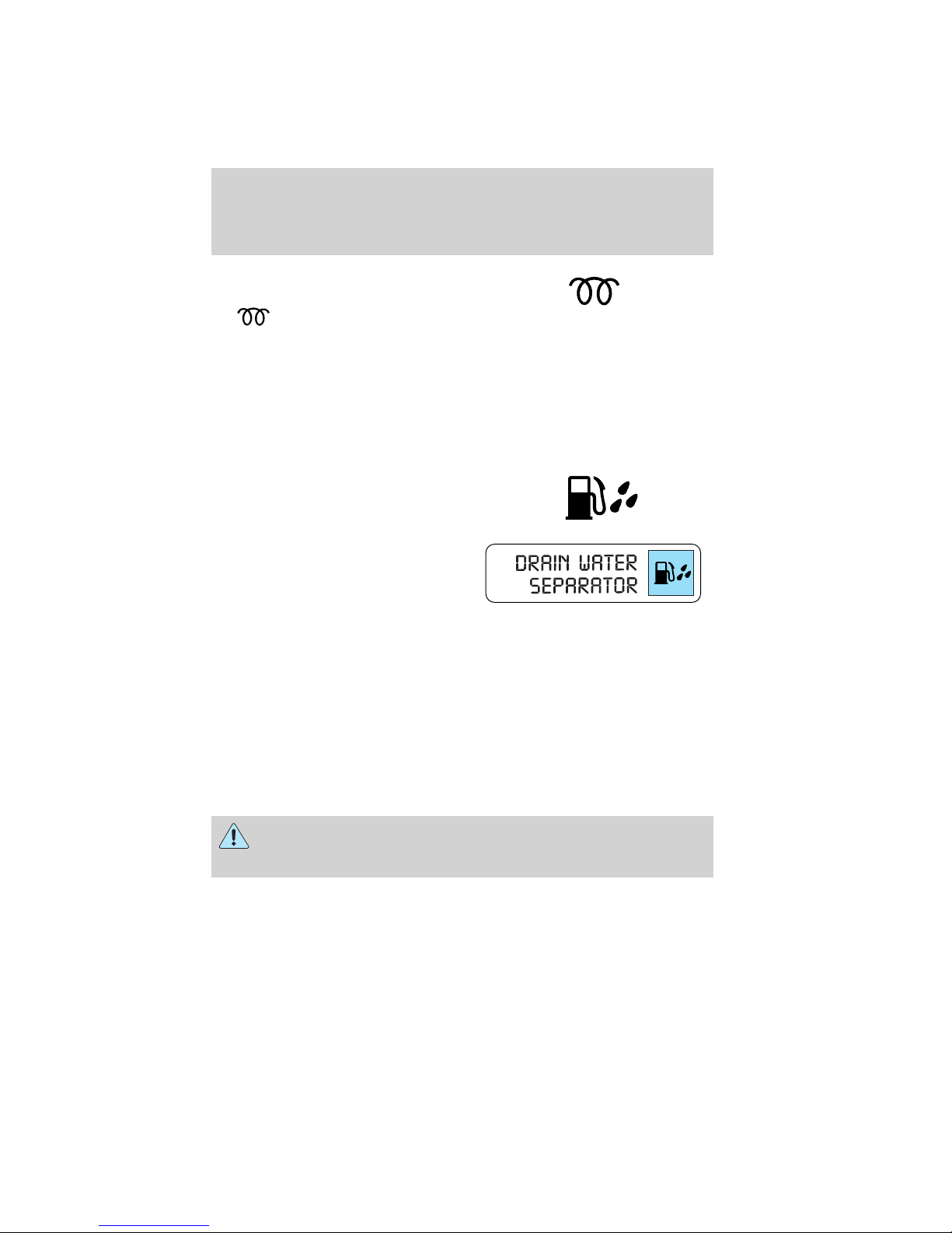
Glow plug pre-heat indicator:
With the key in the on position,
the
plug heat is necessary as a starting aid. Wait until the light goes off
before starting. Refer to Cold weather starting in the Driving chapter
of this supplement. After the engine starts, the light should turn on. The
light should always illuminate at least momentarily when the engine is
cold and the ignition is turned to on. If it does not illuminate, the glow
plug system should be checked and repaired promptly to avoid difficulty
in cold starting.
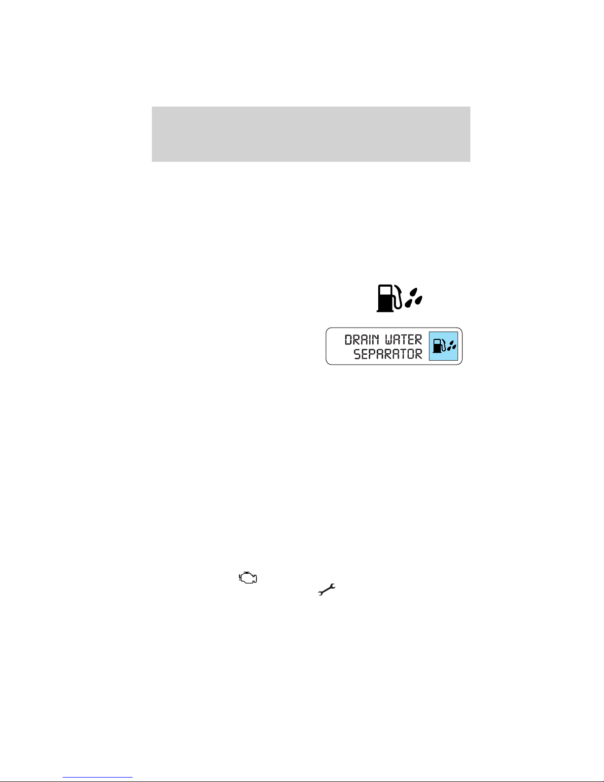
Water in fuel:
F-Super Duty
E-Series
During refueling, it is possible for water-contaminated diesel fuel to be
pumped into your tank. Your vehicle’s fuel system is equipped with a fuel
filter/water separator to remove water from the fuel. The water in fuel
light will illuminate when the FCM/HFCM has a significant quantity of
water in it.
If the light illuminates when the engine is running, stop the vehicle as
soon as safely possible, shut off the engine, then drain the FCM/HFCM.
Refer to Draining the FCM/HFCM and changing the fuel filters in the
Maintenance and Specifications chapter of this supplement for the
drain procedure. Allowing water to stay in the system could result in
extensive damage to, or failure of, the fuel injection system.
light will illuminate if glow
WARNING: Do not drain the water separator while the engine is
running. Fuel may ignite if the separator is drained while the
engine is running or the vehicle is moving.
2010 Econoline (eco)
Supplement (supplement), 1st Printing
USA (fus)
9

Instrument Cluster
Engine oil pressure:
Illuminates when the oil pressure
falls below the normal range. Refer
to Engine oil in the Maintenance and Specifications chapter for more
information.
GAUGES
Engine boost gauge (F-Super Duty only):
Indicates the amount of pressure in
the engine. Driving with your
pointer continuously at the high end
of the scale may damage the engine.
10
2010 Econoline (eco)
Supplement (supplement), 1st Printing
USA (fus)

Driving
STARTING THE ENGINE
Read all starting instructions carefully before you start your vehicle.
For temperatures below 32°F (0°C), the use of the correct grade engine
oil is essential for proper operation. Refer to Engine oil specifications
in the Maintenance and Specifications chapter for more information.
Your vehicle may be equipped with a cold weather starting strategy that
prevents severe engine damage by assisting in engine lubrication
warm-up. In extremely cold ambient temperatures, this strategy activates
and prevents the accelerator pedal from being used for 30 seconds after
starting the vehicle. By not allowing the accelerator pedal to be used, the
engine oil is allowed to properly lubricate the bearings preventing engine
damage due to lack of proper lubrication. After the 30 second warm-up
period, the accelerator pedal will be operational again as long as the
pedal is not being pressed when the 30 second time limit expires. When
starting the engine in extremely cold temperatures (-15°F [–26°C]), it is
recommended to allow the engine to idle for several minutes before
driving the vehicle.
If your vehicle is equipped with a manual transmission, make sure
the parking brake is fully set before you turn the key. Depress the clutch
pedal and place the gearshift in the neutral position. The clutch must be
fully depressed in order to operate the starter. Do not press the
accelerator during starting.
If your vehicle is equipped with an automatic transmission, ensure
the gearshift lever is in P (Park) and the parking brake is fully set before
you turn the key. Do not press the accelerator during starting.
Engine-driven cooling fan (fan clutch)
Your vehicle is equipped with an engine driven cooling fan drive (also
called a fan clutch). This fan drive changes the fan speed to match the
vehicle’s changing cooling air flow requirements. Fan speed, fan noise
level and fuel consumption all will increase based on the driving
conditions that include trailer towing, hill climbing, heavy loads, high
speed and high ambient temperature, individually or in combination. The
fan drive is designed to provide the minimum fan speed (and resulting
fan noise and fuel consumption) required to meet the ever changing
vehicle cooling air flow requirements. You will hear the amount of fan
noise increasing and decreasing as the engine power requirements and
vehicle driving conditions change as you drive. This is to be expected as
being normal to the operation of your vehicle. High levels of fan noise
might also be heard when your engine is first started, and should
normally decrease after driving for a short time.
11
2010 Econoline (eco)
Supplement (supplement), 1st Printing
USA (fus)
Driving
Cold weather starting
It is recommended that the engine block heater be used for starting
when the temperature is -10°F (-23°C) or colder. Refer to Engine block
heater (if equipped) in the Driving chapter of the Owner’s Guide.
When operating in cold weather, use Motorcraft Cetane improvers or non
alcohol-based Cetane improvers from a reputable manufacturer.
Do not crank the engine for more than 10 seconds as starter damage
may occur. If the engine fails to start, turn the key to 3 (off) and wait
30 seconds before trying again.
WARNING: Do not use starting fluid, such as ether, in the air
intake system (see air filter decal). Such fluid could cause
immediate explosive damage to the engine and possible personal injury.
WARNING: Do not add gasoline, gasohol or alcohol to diesel
fuel. This practice creates a serious fire hazard and causes
engine performance problems.
1. Turn the key to on without turning the key to start. Do not start the
engine until the glow-plug pre-heat indicator
2. When the glow plug pre-heat
indicator turns off, turn the key to
start, then release the key as soon
as the engine starts. The glow plugs
will continue to be activated for two minutes after the glow plug pre-heat
indicator
glow plug activation time ends, the glow plugs will need to be reset by
turning the key to off.
3. After the engine starts, allow it to idle for about 15 seconds. This
is to protect the engine. Do not increase engine speed until the oil
pressure gauge indicates normal pressure.
has turned off. If the engine is not started before the
turns off.
12
2010 Econoline (eco)
Supplement (supplement), 1st Printing
USA (fus)

Driving
ENGINE IDLE SHUTDOWN (IF EQUIPPED)
Your vehicle may be equipped with an engine idle shutdown system. This
system will automatically shut down your engine when it has been idling
in P (Park) or N (Neutral) for five minutes (parking brake set) or
15 minutes (parking brake not set). When the engine idle shutdown
process has started:
• A chime will sound and the message center will display ENGINE
TURNS OFF IN XX 30 seconds prior to shutdown and begins
counting down to zero.
• The timer can be reset by changing the position of the accelerator
pedal, brake pedal or the park brake within the final 30 seconds.
• When the timer reaches zero, the engine shuts down and the message
center will display ENGINE TURNED OFF.
• One minute after the engine has shut down, the electrical system will
simulate key off, even though the ignition is still in the on position,
initiating normal accessory delay period.
• The ignition must be moved to the off position to reset the system
before restarting the vehicle.
Note: The engine idle shutdown idle timer will not start if:
• The engine is operating in power take-off (PTO) mode.
• The engine coolant temperature is below 60°F (16°C).
• The exhaust emission control device (DPF) is regenerating.
STOPPING THE ENGINE
Turn the ignition to the OFF position.
On E-Series vehicles, to prolong engine life (after extended high speed
or maximum GVW operation), it is recommended that a hot engine be
idled for 7–10 minutes which will allow the turbocharged engine to cool
down.
On F-Super Duty vehicles, to prolong engine life (especially after
extended high speed, high ambient temperature, or high GVW/GCW
operation), it is recommended that a hot engine be idled for 3-5 minutes
which will allow the turbocharged engine to cool down.
13
2010 Econoline (eco)
Supplement (supplement), 1st Printing
USA (fus)

Driving
COLD WEATHER OPERATION
Changing to a lighter grade engine oil also makes starting easier under
these conditions. Refer to Engine oil specifications in the Maintenance
and Specifications chapter of this supplement.
Diesel fuel is adjusted seasonally for cold temperatures. Diesel fuel which
has not been properly formulated for the ambient conditions may form
wax crystals which can clog the fuel filter. At temperatures below 20°F
(–7°C), if the engine starts, stalls after a short time, and then will not
restart, the fuel filter(s) may be clogged. For best results in cold
weather, use a diesel fuel which has been formulated for the ambient
conditions. If you have been using biodiesel, you may need to use a fuel
with lower biodiesel content, try another brand, or discontinue using
biodiesel.
Your vehicle is equipped with either an FCM or HFCM which recirculates
fuel from the engine to help prevent fuel filter clogging. Your vehicle is
also equipped with a bypass relief valve, located in the fuel tank pick-up
boot, which provides fuel flow to the engine if the fuel pickup should
become plugged. To allow the bypass valve to function and avoid engine
fuel starvation during cold weather operation of 32°F (0°C) or below, it
is recommended that the fuel level in your tank should not be allowed to
drop below
system and stalling the engine.
In cold weather below 32°F (0°C), the engine will slowly increase to a
higher idle speed if left idling in P (Park). As the engine warms-up, the
engine sound level will decrease due to the activation of PCM-controlled
sound reduction features.
If your vehicle is operated in a heavy snow storm or blowing snow
conditions, the engine air induction may become partially clogged with
snow and/or ice. If this occurs, the engine may experience a significant
reduction in power output. At the earliest opportunity, clear all the snow
and/or ice away from inside the air filter assembly. Take the top off the
assembly, leaving the air filter in, and remove any snow or ice.
In order to operate the engine in temperatures of 32°F (0°C) or lower,
read the following instructions:
• Make sure that the batteries are of sufficient size and are fully
charged. Check other electrical components to make sure they are in
optimum condition.
• Use Motorcraft Premium Engine Coolant solution at the concentration
recommended to protect the engine against damage from freezing.
• Try to keep the fuel tank full as much as possible at the end of
operation to prevent condensation in the fuel system.
14
1
⁄4full. This will help prevent air from entering the fuel
2010 Econoline (eco)
Supplement (supplement), 1st Printing
USA (fus)

Driving
• Make sure you use proper cold weather engine oil and that it is at its
proper level. Also, if necessary, make sure to follow the engine oil and
filter change schedule found under the Special operating conditions
section in the scheduled maintenance guide information.
• At temperatures of -10°F (-23°C) or below, it is recommended that
you use an engine block heater to improve cold engine starting.
• If operating in arctic temperatures of -20°F (-29°C) or lower, consult
your truck dealer for information about special cold weather
equipment and precautions.
Note: Idling in cold weather will not heat the engine to its normal
operating temperature. Long periods of idling in cold weather can cause
a buildup of heavy deposits of carbon and rust on valve stems causing
them to stick, which in turn, can cause valve train damage.
The following cold weather idling guidelines must be followed:
• Avoid idling the engine for more than 10 minutes at a time.
• Use Motorcraft Cetane improvers or non alcohol-based cetane
improvers from a reputable manufacturer.
• Maintain the engine cooling system properly.
• Do not shut the engine down after an extensive idling period
(10 minutes or more). Drive the vehicle for several miles with the
engine at normal operating temperatures under a moderate load to
burn off any accumulated carbon and varnish.
• Consider using an engine block heater.
• For extended idle times use an approved idle speed increase device.
Winter operating tips for Arctic operation -20°F (-29°C) and below
The following information is provided as a guideline only, and is not
intended to be the only source of possible solutions in resolving extreme
cold temperature issues.
Starting aids:
The use of the factory engine block heater (refer to Engine block heater
[if equipped] in the Driving chapter of the Owner’s Guide) and oil pan
heaters (aftermarket) will assist in engine starting, in extreme cold
ambient temperatures.
WARNING: Do not use starting fluid, such as ether, in the air
intake system (see air filter decal). Such fluid could cause
immediate explosive damage to the engine and possible personal injury.
2010 Econoline (eco)
Supplement (supplement), 1st Printing
USA (fus)
15

Driving
Idle control:
For periods of extended idle, the throttle should be set at an rpm that is
sufficient to keep the engine at normal operating temperatures. This
action can reduce the amount of engine damaging deposits.
• The engine contains a unique “Cold Weather - Idle up feature”
calibration strategy within the PCM. Under the appropriate conditions,
the strategy will automatically elevate the engine idle speed after
130 seconds of idling in cold ambient temperatures. For this feature to
be activated, the truck must be in P (Park) (for automatic
transmission), in neutral (for manual transmission) with the parking
brake applied and engine oil temperature below 158°F (70°C). This
strategy raises the rpm to a level that reduces the potential to
produce “coking” or “wet stacking”, which is common to all diesel
engines when idling for extended periods during cold ambient
temperatures.
• Your vehicle may have a factory option for a Stationary Elevated Idle
Control (SEIC) through dash-mounted Upfitter switches will allow the
operator to elevate the idle rpm for extended idle periods, as well as
aftermarket equipment such as PTO operation. This feature must be
configured even if ordered from the factory. See your authorized
dealer for required upfitting.
Operation in snow
Vehicle operation in heavy snowfall or extreme rain conditions may feed
excessive amounts of snow/water into the air intake system. This could
plug/soak the air filter with snow and may cause the engine to lose
power and possibly shut down.
You may not need to change the air filter and the vehicle may be driven
up to 200 miles (320 km) under the following conditions:
• Snow: At the earliest opportunity, open the hood and clear all the
snow and ice from the air filter housing inlet (do NOT remove the air
filter) and reset the air filter restriction gauge.
• Wet: The air filter will dry after about 15–30 minutes at highway
speeds. At the earliest opportunity, open the hood and reset the air
filter restriction gauge.
Refer to Air filter and restriction gauge in the Maintenance and
Specifications chapter of this supplement for more information.
16
2010 Econoline (eco)
Supplement (supplement), 1st Printing
USA (fus)
Driving
Operation in standing water
Ingestion of water into the diesel engine can result in immediate and
severe damage to the engine. If driving through water, slow down to
avoid splashing water into the intake. If the engine stalls, and ingestion
of water into the engine is suspected, do not try to restart the engine.
Consult your dealer for service immediately.
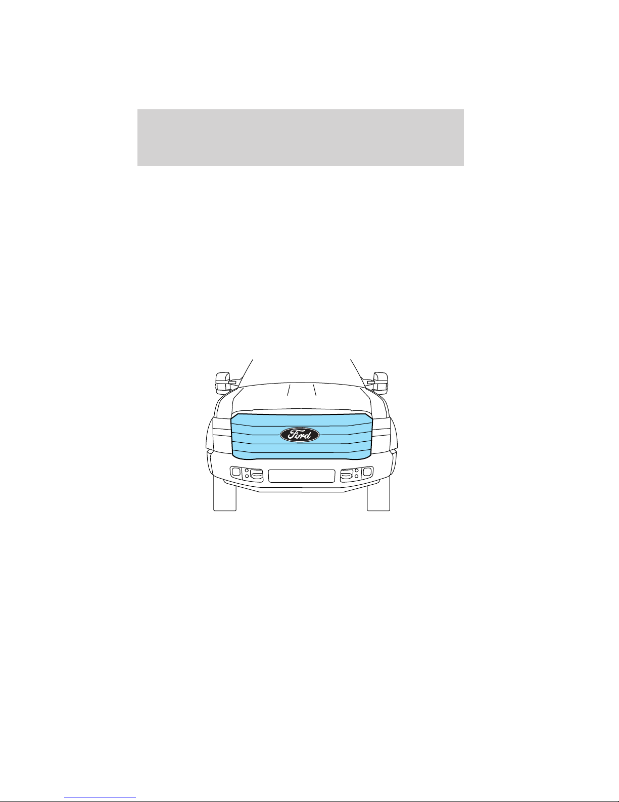
Winter grille cover (F-Super Duty only) (if equipped)
If your vehicle includes a winter grille cover, it will enhance heater
performance and will reduce the amount of time it takes to warm the
inside of your vehicle in extremely cold conditions (below 0°F [-18°C]).
The winter grille cover installs over the outside of the grille of your
vehicle and restricts the air flowing to the engine compartment by
covering the radiator grille openings.
Usage guidelines
The winter grille cover should only be used while operating your vehicle
in extremely cold temperatures or in heavy snow for extended periods of
time. In these temperatures, the vehicle does not need a large amount of
air to properly cool the engine. During periods of operation when more
airflow is required to cool the vehicle, the winter grille cover should not
be used. The following usage guidelines will allow adequate airflow for
proper radiator and air cooler performance.
2010 Econoline (eco)
Supplement (supplement), 1st Printing
USA (fus)
17

Driving
• Do not use the winter grille cover when temperatures are above 50°F
(10°C). Use of the cover in these conditions could cause your vehicle
to overheat. If this happens while the cover is being used, remove the
cover and store properly.
• Do not use the winter grille cover above 32°F (0°C) if towing a trailer.
The added power needed to tow a trailer requires the radiator grille to
have full airflow under all conditions. Your vehicle may overheat if the
cover is used while towing a trailer.
• Do not modify the winter grille cover. The winter grille cover does not
block some sections of the front of the vehicle because these openings
are needed to provide enough airflow to the radiator and air cooler in
extremely cold temperatures.
Installation instructions
The “Installation Instructions” included with your winter grille cover
packaging explain how to install and remove your vehicle’s winter grille
cover. When installing or removing the winter grille cover, refer to the
“Usage guidelines” listed previously. When you first attempt to fit the
winter grille cover, it may appear to be undersized. This is due to the
nature of the special vinyl, which will stretch during installation to
ensure a tight fit. For this reason, the initial installation of the winter
grille cover is best performed when the cover is warm.
Engine block heater (if equipped)
Refer to the Driving chapter in the Owner’s Guide.
Rapid Heat supplemental heating system (if equipped)
The optional Rapid Heat feature is an electrically powered device that is
designed to provide supplemental heat during engine warm up. For
maximum effectiveness mid to low blower speed is recommended during
initial warm up. When operating in automatic mode (when equipped) the
climate control unit will determine the appropriate blower speed for
existing conditions.
Note: Additional aftermarket electrical loads operated during engine
warm up may impact the performance of the Rapid heat supplemental
heater.
18
2010 Econoline (eco)
Supplement (supplement), 1st Printing
USA (fus)

Driving
DUAL FUEL TANK SELECTOR CONTROL (IF EQUIPPED)
If your vehicle is equipped with dual
fuel tanks, you will have a selector
control, located to the right of the
steering wheel, which allows you to
draw fuel from either tank. Your fuel
gauge will display the amount of
fuel in the currently selected tank.
Fuel level indication is delayed for several minutes when the tank
selector switch is actuated. Fuel level indication can be obtained
immediately by turning off and restarting the engine.
TRAILER TOWING
Refer to your Owner’s Guide for full details on towing a trailer.
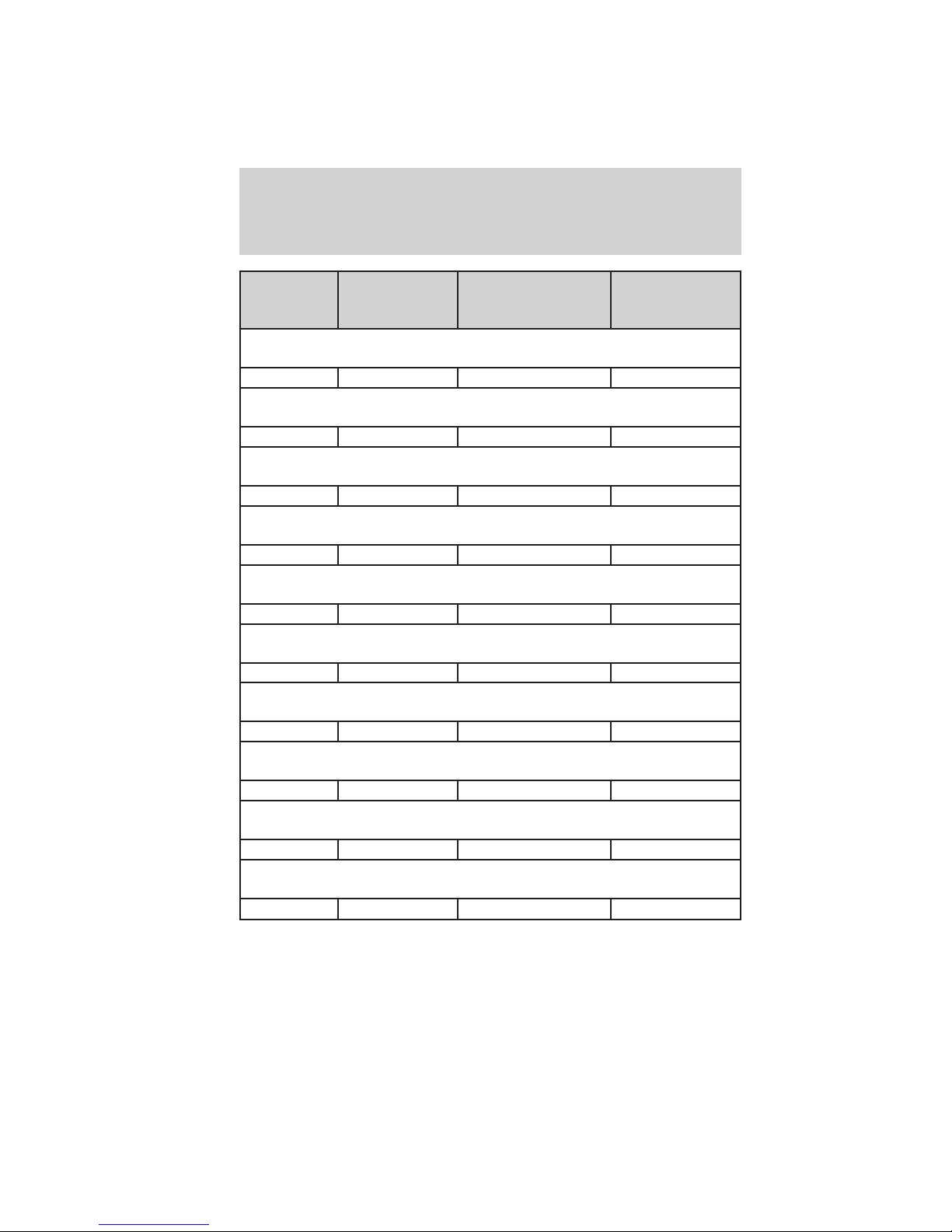
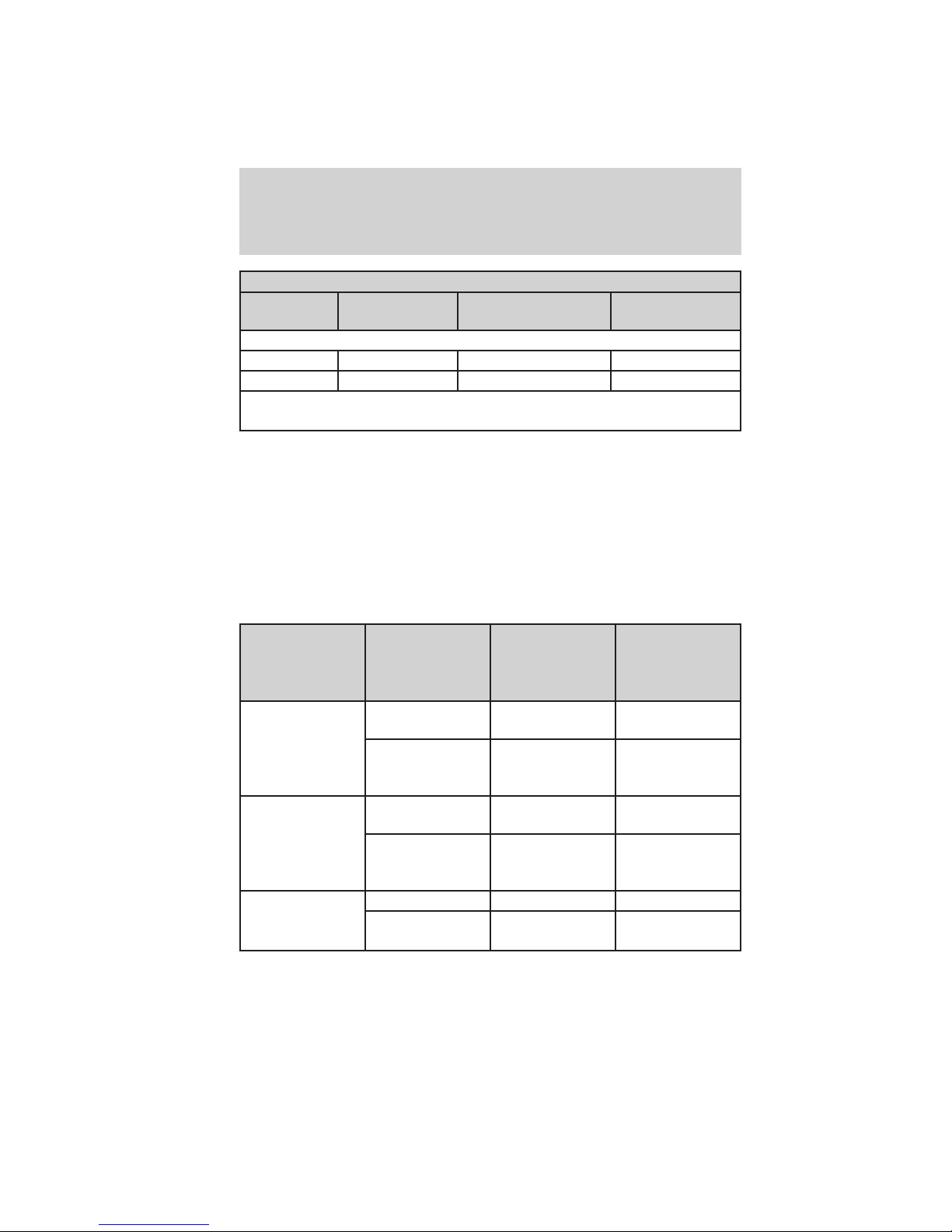
Trailer towing tables - E-Series
Engine Rear axle
ratio
E-350 Regular Van (9500 GVWR)
6.0L 3.55 16000 (7257) 9500 (4309)
6.0L 4.10 20000 (9072) 10000 (4536)
E-350 Extended/RV Van (9500 GVWR)
6.0L 3.55 16000 (7257) 9400 (4264)
6.0L 4.10 20000 (9072) 10000 (4536)
E-350 Regular Wagon (12–passenger) (8950 GVWR)
6.0L 3.55 16000 (7257) 8900 (4037)
6.0L 4.10 20000 (9072) 10000 (4536)
138” Wheelbase 9900 GVWR E-350 Cutaway with Single Rear
6.0L 4.10 20000 (9072) 10000 (4536)
Maximum GCWR -
lbs. (kg)
Wheels (SRW)
Maximum
trailer weight -
lbs. (kg)
19
2010 Econoline (eco)
Supplement (supplement), 1st Printing
USA (fus)
Driving
Engine Rear axle
ratio
138” Wheelbase 10050 GVWR E-350 Cutaway with Single Rear
6.0L 4.10 20000 (9072) 10000 (4536)
138” Wheelbase 10000 GVWR E-350 Cutaway with Dual Rear
6.0L 4.10 20000 (9072) 10000 (4536)
138” Wheelbase 11500 GVWR E-350 Cutaway with Dual Rear
6.0L 4.10 20000 (9072) 10000 (4536)
158” Wheelbase 10050 GVWR E–350 Cutaway with Single Rear
6.0L 4.10 20000 (9072) 10000 (4536)
158” Wheelbase 10000 GVWR E–350 Cutaway with Dual Rear
6.0L 4.10 20000 (9072) 10000 (4536)
158” Wheelbase 11500 GVWR E–350 Cutaway with Dual Rear
6.0L 4.10 20000 (9072) 10000 (4536)
158” Wheelbase 12500 GVWR E–350 Cutaway with Dual Rear
6.0L 4.10 20000 (9072) 10000 (4536)
176” Wheelbase 10000 GVWR E–350 Cutaway with Dual Rear
6.0L 4.10 20000 (9072) 10000 (4536)
176” Wheelbase 12500 GVWR E–350 Cutaway with Dual Rear
6.0L 4.10 20000 (9072) 10000 (4536)
158” Wheelbase 13990 GVWR E–450 Cutaway with Dual Rear
6.0L 4.10 20000 (9072) 10000 (4536)
Maximum GCWR -
lbs. (kg)
Wheels (SRW)
Wheels (DRW)
Wheels (DRW)
Wheels (SRW)
Wheels (DRW)
Wheels (DRW)
Wheels (DRW)
Wheels (DRW)
Wheels (DRW)
Wheels (DRW)
Maximum
trailer weight -
lbs. (kg)
20
2010 Econoline (eco)
Supplement (supplement), 1st Printing
USA (fus)
Driving
Engine Rear axle
ratio
158” Wheelbase 14500 GVWR E–450 Cutaway with Dual Rear
6.0L 4.10 20000 (9072) 10000 (4536)
176” Wheelbase 13990 GVWR E–450 Cutaway with Dual Rear
6.0L 4.10 20000 (9072) 10000 (4536)
176” Wheelbase 14500 GVWR E–450 Cutaway with Dual Rear
6.0L 4.10 20000 (9072) 10000 (4536)
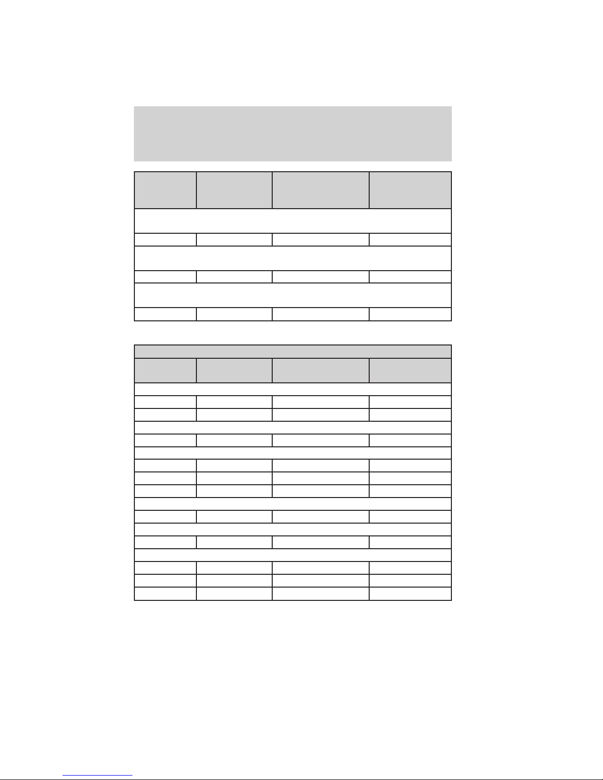
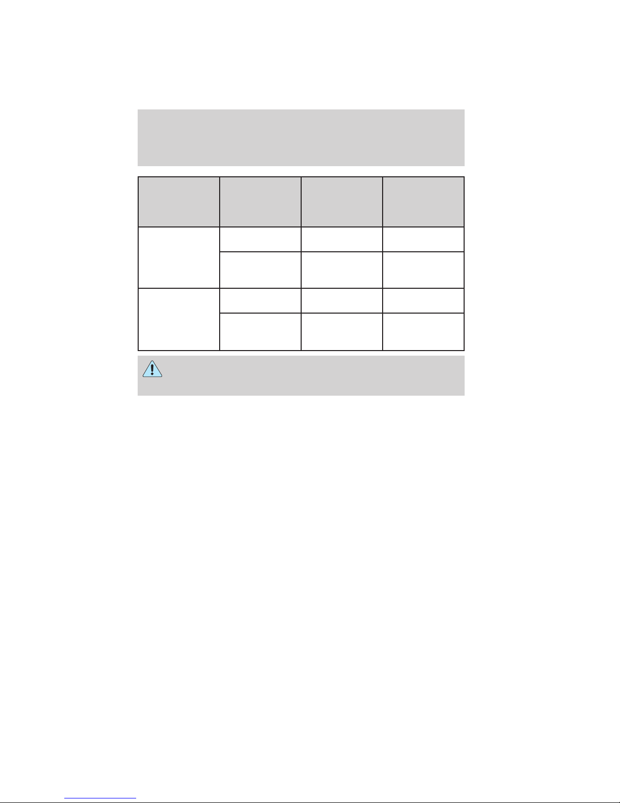
Trailer towing tables - F-Super Duty
Maximum GCWR - lb (kg.)
Engine Rear axle
ratio
F–250/F–350 Single Rear Wheel (SRW) Pick-up
6.4L 3.31 — 23000 (10433)
6.4L 3.55 23000 (10433) 23000 (10433)
F–350 Single Rear Wheel (SRW) Chassis Cab
6.4L 3.73 — 23000 (10433)
F–350 Dual Rear Wheel (DRW) Pick-up
6.4L 3.73/4.10 23500 (10659) —
6.4L 3.73 — 23500 (10659)
6.4L 4.10 — 26000 (11793)
F–350 Dual Rear Wheel (DRW) Chassis Cab
6.4L 3.73/4.10 23500 (10659) 23500 (10659)
6.4L 4.30 27000 (12247) 33000 (14969)
6.4L 4.30 26000 (11793) 26000 (11793)
6.4L* 4.30 — 30000 (13608)
6.4L* 4.88 28000 (12701) —
Maximum GCWR -
lbs. (kg)
Wheels (DRW)
Wheels (DRW)
Wheels (DRW)
Manual
transmission
F–450 Pick-up
F–450 Chassis Cab
Maximum
trailer weight -
lbs. (kg)
Automatic
transmission
2010 Econoline (eco)
Supplement (supplement), 1st Printing
USA (fus)
21
Driving
Maximum GCWR - lb (kg.)
Engine Rear axle
ratio
F–550 Chassis Cab
6.4L 4.30/4.88 26000 (11793) 26000 (11793)
6.4L* 4.88 28000 (12701) 33000 (14969)
* With high capacity trailer tow package; see rear axle label to identify
actual vehicle content.
Integrated hitch rating
The standard integrated hitch has two ratings depending on mode of
operation:
• Weight carrying - requires a draw bar and hitch ball. The draw bar
supports all the vertical tongue load of the trailer.
• Weight distributing - requires an aftermarket weight distributing
system which includes draw bar, hitch ball, spring bars and snap-up
brackets. The vertical tongue load of the trailer is distributed between
the truck and the trailer by this system.
Manual
transmission
Automatic
transmission
F–250/350 DRW
Pick-ups 2.5” ID
without adapter
(requires 2.5”
drawbar)
F–250/350 DRW
Pick-ups 2.5” ID
with adapter*
(requires 2”
drawbar)
All SRW
Pick-ups 2”
receiver
22
Maximum
Hitch Type
Weight carrying 8000 (3629) 800 (363)
Weight
distributing
Weight carrying 6000 (2721) 600 (272)
Weight
distributing
Weight carrying 6000 (2721) 600 (272)
Weight
distributing
Gross Trailer
Weight-lb
(kg)
15000 (6804) 1500 (680)
12500 (5670) 1250 (567)
12500 (5670) 1250 (567)
Maximum
Tongue Weight
- lb (kg)
2010 Econoline (eco)
Supplement (supplement), 1st Printing
USA (fus)
Driving
Maximum
Hitch Type
F–450 DRW
Pick-ups 2.5” ID
without adapter
(requires 2.5”
drawbar)
F–450 DRW
Pick-ups 2.5” ID
with adapter*
(requires 2”
drawbar)
WARNING: Towing trailers beyond the maximum tongue weight
exceeds the limit of the towing system and could result in
vehicle structural damage, loss of vehicle control and personal injury.
* Trailer hitch adapter is available from Ford dealers (Part number:
5C3Z-19H282–A).
Weight carrying 8000 (3629) 800 (363)
Weight
distributing
Weight carrying 6000 (2721) 600 (272)
Weight
distributing
Gross Trailer
Weight-lb
(kg)
16000 (7258) 1600 (726)
12500 (5670) 1250 (567)
Maximum
Tongue Weight
- lb (kg)
2010 Econoline (eco)
Supplement (supplement), 1st Printing
USA (fus)
23

Roadside Emergencies
JUMP STARTING YOUR VEHICLE (E-SERIES ONLY)
The following procedure is for E-Series vehicles only. F-Super
Duty vehicles equipped with the 6.4L diesel engine can be jump
started using the same procedure as a gasoline engine; refer to
your Owner’s Guide for the jump starting procedure.
WARNING: The gases around the battery can explode if
exposed to flames, sparks, or lit cigarettes. An explosion could
result in injury or vehicle damage.
WARNING: Batteries contain sulfuric acid which can burn skin,
eyes and clothing, if contacted.
Do not attempt to push-start your vehicle. Automatic
transmissions do not have push-start capability; damage to the
automatic transmission may result.
Preparing your vehicle
When the batteries are disconnected or new batteries are installed, the
transmission must relearn its shift strategy. As a result, the transmission
may have firm and/or soft shifts. This operation is considered normal and
will not affect function or durability of the transmission. Over time, the
adaptive learning process will fully update transmission operation.
1. Use only a 12–volt supply to start your vehicle.
2. Do not disconnect the batteries of the disabled vehicle as this could
damage the vehicle’s electrical system.
3. Park the booster vehicle close to the passenger side of the disabled
vehicle making sure the two vehicles do not touch. Set the parking
brake on both vehicles.
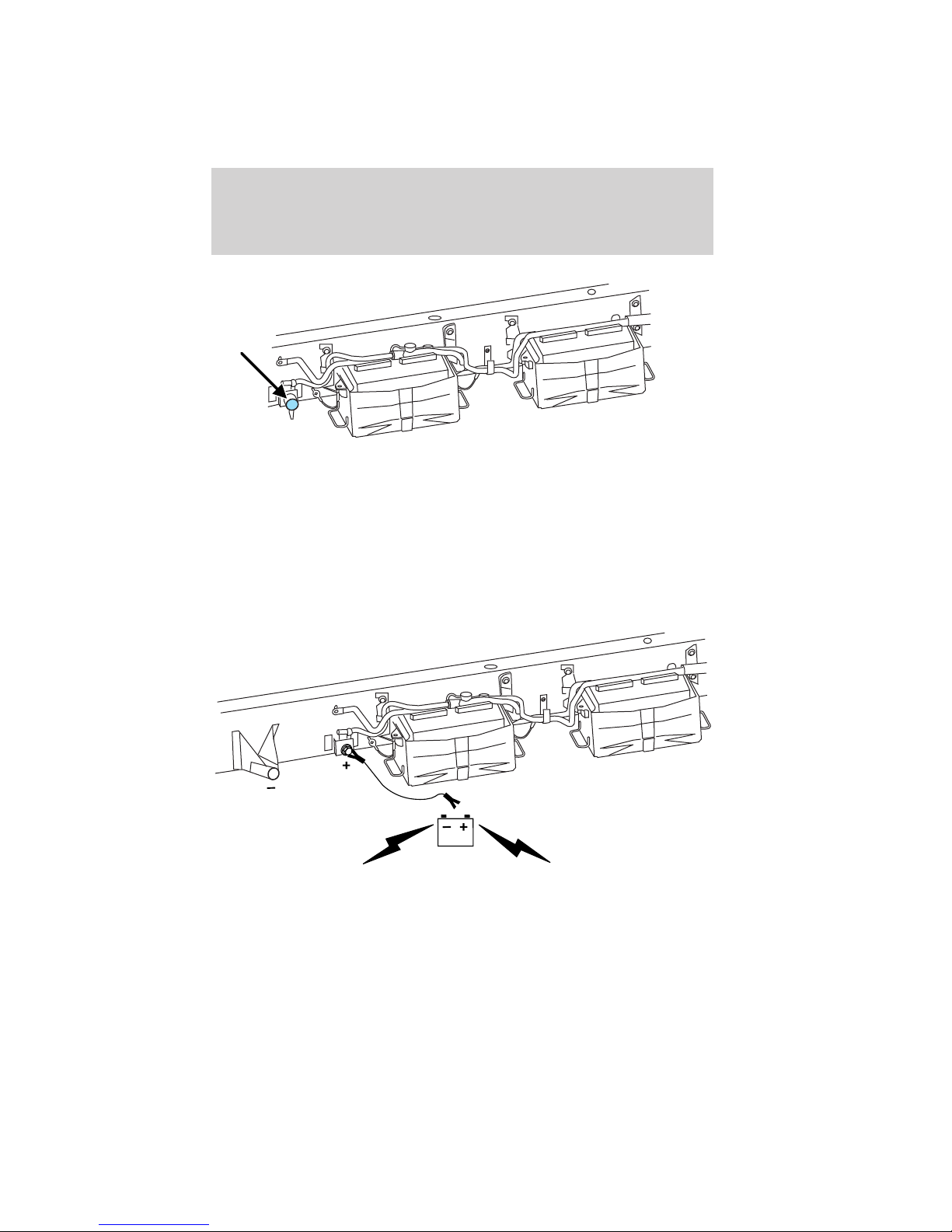
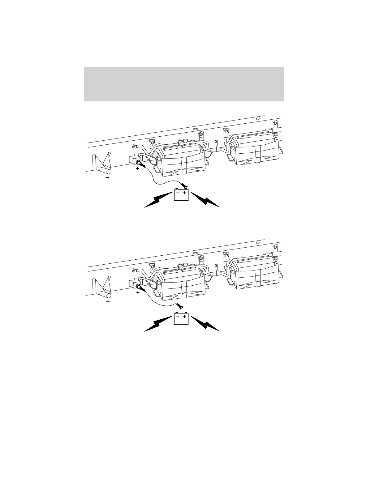
Note: This vehicle has two frame-mounted batteries located on the
passenger side frame rail, behind the front passenger door. A battery
positive (+) jumper stud is located on the frame rail behind the rear
most battery box.
24
2010 Econoline (eco)
Supplement (supplement), 1st Printing
USA (fus)
Roadside Emergencies
• Location of positive (+) jumper stud; remove the cap to access the
jumper stud.
4. Check the assisting vehicle battery terminals and the positive (+)
jumper stud and remove any excessive corrosion before you attach the
battery cables. Ensure that accessible vent caps are tight and level.
5. Turn the heater fan on in both vehicles to protect from any electrical
surges. Turn all other accessories off.
Connecting the jumper cables
1. Connect the positive (+) jumper cable to the positive (+) jumper stud
located on the passenger side frame rail of the disabled vehicle.
Note: In the illustrations, lightning bolts are used to designate the
assisting (boosting) battery.
2010 Econoline (eco)
Supplement (supplement), 1st Printing
USA (fus)
25

Roadside Emergencies
2. Connect the other end of the positive (+) cable to the positive (+)
terminal of the assisting battery.
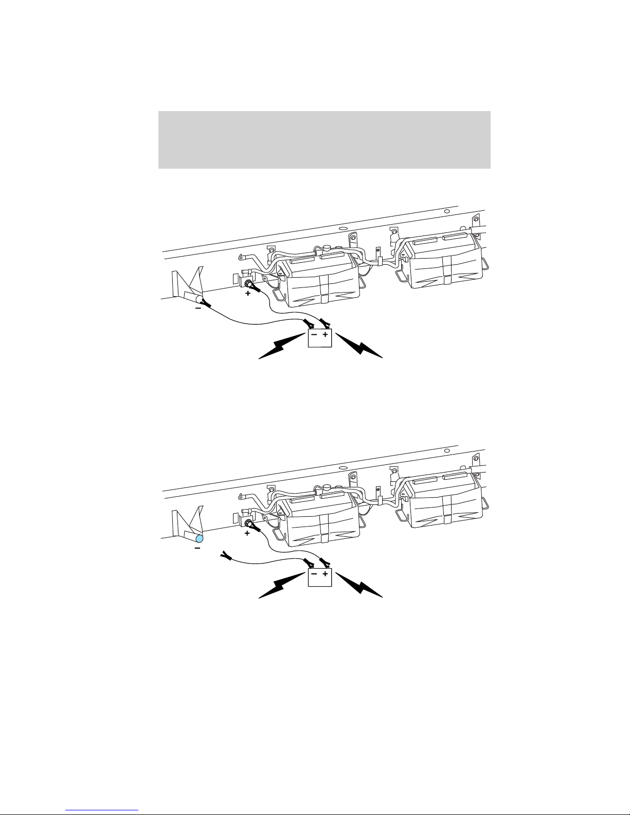
3. Connect the negative (-) cable to the negative (-) terminal of the
assisting battery.
26
2010 Econoline (eco)
Supplement (supplement), 1st Printing
USA (fus)

Roadside Emergencies
4. Make the final connection of the negative (-) cable to an exposed
metal part of the disabled vehicle’s frame or chassis, away from the
batteries. Do not use fuel lines, brake lines, exhaust components or the
battery trays as grounding points.
WARNING: Do not connect the end of the second cable to the
negative (-) terminal of the battery to be jumped. A spark may
cause an explosion of the gases that surround the battery.
5. Ensure that the cables are clear of moving parts or any fuel delivery
system, brake system or exhaust system parts.
Jump starting
1. Start the engine of the booster vehicle and run the engine at
moderately increased speed.
2. Start the engine of the disabled vehicle.
3. Once the disabled vehicle has been started, run both engines for an
additional three minutes before disconnecting the jumper cables.
2010 Econoline (eco)
Supplement (supplement), 1st Printing
USA (fus)
27
Roadside Emergencies
Removing the jumper cables
Remove the jumper cables in the reverse order that they were
connected.
1. Remove the jumper cable from the ground metal surface.
Note: In the illustrations, lightning bolts are used to designate the
assisting (boosting) battery.
2. Remove the jumper cable on the negative (-) connection of the
booster vehicle’s battery.
28
2010 Econoline (eco)
Supplement (supplement), 1st Printing
USA (fus)
Roadside Emergencies
3. Remove the jumper cable from the positive (+) terminal of the booster
vehicle’s battery.
4. Remove the jumper cable from the positive (+) jumper stud of the
disabled vehicle. Reinstall the cap onto the jumper stud.
After the disabled vehicle has been started and the jumper cables
removed, allow it to idle for several minutes so the engine computer can
relearn its idle conditions.
2010 Econoline (eco)
Supplement (supplement), 1st Printing
USA (fus)
29
Cleaning
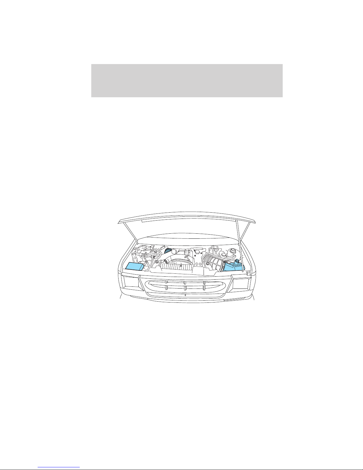
ENGINE
Engines are more efficient when they are clean because grease and dirt
buildup keep the engine warmer than normal. When washing:
• Take care when using a power washer to clean the engine. The
high-pressure fluid could penetrate the sealed parts and cause
damage.
• Do not spray a hot engine with cold water to avoid cracking the
engine block or other engine components.
• Spray Motorcraft Engine Shampoo and Degreaser (ZC-20) on all parts
that require cleaning and pressure rinse clean.
• Never wash or rinse the engine while it is running; water in the
running engine may cause internal damage.
• Cover the highlighted areas to prevent water damage when cleaning
the engine.
• E–Series
30
2010 Econoline (eco)
Supplement (supplement), 1st Printing
USA (fus)
 Loading...