

Ford 2006 Escape J87R Bodyshop Manual

WAR NI NG
Servicing a vehicle can be dangerous. If you have not received
service-related training, the risks of injury, property damage, and
failure of servicing increase. The recommended servicing procedures
for the vehicle in this workshop manual were developed with
Ford-trained technicians in mind. This manual may be useful to
non-Ford trained technicians, but a technician with our
service-related training and experience will be at less risk when
performing service operations. However, all users of this manual are
expected to at least know general safety procedures.
This manual contains "Warnings" and "Cautions" applicable to risks
not normally encountered in a general technician's experience.
They should be followed to reduce the risk of injury and the risk that
improper service or repair may damage the vehicle or render it unsafe.
It is also important to understand that the "Warnings" and "Cautions"
are not exhaustive. It is impossible to warn of all the hazardous
consequences that might result from failure to follow the procedures.
The procedures recommended and described in this manual are
effective methods of performing service and repair. Some require tools
specifically designed for a specific purpose. Persons using procedures
and tools which are not recommended by Ford Motor Company must
satisfy themselves thoroughly that neither personal safety nor safety of
the vehicle will be jeopardized.
The contents of this manual, including drawings and specifications, are
the latest available at the time of printing, and Ford Motor Company
reserves the right to change the vehicle designs and alter the contents
of this manual without notice and without incurring obligation.
Parts should be replaced with genuine Ford replacement parts or with
parts which match the quality of genuine Ford replacement parts.
Persons using replacement parts of lesser quality than that of genuine
Ford replacement parts must satisfy themselves thoroughly that
neither personal safety nor safety of the vehicle will be jeopardized.
Ford Motor Company is not responsible for any problems which may
arise from the use of this manual. The cause of such problems
includes but is not limited to insufficient service-related training, use of
improper tools, use of replacement parts of lesser quality than that of
genuine Ford replacement parts, or not being aware of any revision of
this manual.

CONTENTS
ESCAPE
Bodyshop
Manual
FOREWORD
This bodyshop manual is intended for
use by technicians of Authorized Ford
Dealers to help them service and repair
Ford vehicles. It can also be useful to
owners and operators of Ford vehicles in
performing limited repair and maintenance on
Ford vehicles.
For proper repair and maintenance, a
thorough familiarization with this manual is
important, and should always be kept in
a handy place for quick and easy reference.
All the contents of this manual, including
drawings and specifications, are the latest
available at the time of printing.
As modifications affecting repair or
maintenance occur, relevant information
supplementary to this volume will be
made available at Ford dealers. This
manual should be kept up-to-date.
Ford Motor Company reserves the right to
alter the specifications and contents of this
manual without obligation or advance notice.
All rights reserved. No part of this book may
be reproduced or used in any form or
by any means, electronic or mechanical
including photocopying and recording and
the use of any kind of information storage
and retrieval-system-without permission in
writing.
Ford Motor Company
APPLICATION:
This manual is applicable to vehicles
beginning with the Vehicle Identification
Numbers (VIN), shown on the following
page.
© 2006 Mazda Motor Corporation
MARCH 2006
F342–20–06C
Title
Section
GENERAL INFORMATION
00
DIMENSIONS
80A
CONSTRUCTION
80B
PANEL REPLACEMENT
80C
WATER-PROOF AND RUST PREVENTIVE
TREATMENT
80D
PLASTIC BODY PARTS
80E
PRIMARY COLOR MIXTURE CHART FOR
BODY COLORS
80F

00-00–1
00
GENERAL INFORMATION
SECTION
00
To c of S CT
GENERAL INFORMATION . . . 00-00
To c of S CT
00-00 GENERAL INFORMATION
VEHICLE IDENTIFICATION NUMBER
(VIN) CODE . . . . . . . . . . . . . . . . . . . . . . 00-00–1
VEHICLE IDENTIFICATION NUMBERS
(VIN). . . . . . . . . . . . . . . . . . . . . . . . . . . . 00-00–1
HOW TO USE THIS MANUAL. . . . . . . . . 00-00–2
SERVICE PRECAUTIONS. . . . . . . . . . . . 00-00–6
EFFICIENT REMOVAL OF BODY
PANELS . . . . . . . . . . . . . . . . . . . . . . . . . 00-00–7
INSTALLATION PREPARATIONS . . . . . . 00-00–9
EFFICIENT INSTALLATION OF
BODY PANELS. . . . . . . . . . . . . . . . . . . . 00-00–10
ANTICORROSION, SOUND INSULATION,
AND VIBRATION INSULATION . . . . . . . 00-00–13
ABBREVIATION . . . . . . . . . . . . . . . . . . . . 00-00–14
End of Toc
BM: GENERAL INFORMATION
VEHICLE IDENTIFICATION NUMBER (VIN) CODE
id000000600800
End Of Sie
VEHICLE IDENTIFICATION NUMBERS (VIN)
id000000600100
LFA CKZTNX*2 000001—
LFA CLZTNX*2 000001—
LFA CMZTVX*2 000001—
LFA CNZTVX*2 000001—
LFA YKZTNX*2 000001—
LFA YLZTNX*2 000001—
LFA YMZTVX*2 000001—
LFA YNZTVX*2 000001—
End Of Sie
L F A C K Z T N X 7 2 1 2 3 4 5 6
Assemble Plant
Serial No.
2= FLH FAP2 Plant
Engine type
N= L3 (2.3L)
V= AJ (3.0L Duratec)
Model
Gross vehicle weight and Air bags
LFA= Ford Lio Ho
World manufacturer identification
C= 4001—5000 lbs {1814—2268 kg},
with Driver, Passenger and Side air bag
Y= 4001—5000 lbs {1814—2268 kg},
with Driver and Passenger air bag
Constant
Model year
X
6=2006, 7= 2007, 8= 2008
KZT= 4x4, Export 2.3L, 4WD, XLS, 4EAT, ABS
LZT= 4x4, Export 2.3L, 4WD, XLT, 4EAT, ABS
MZT= 4x4, Export 3.0L, 4WD, 4EAT, ABS
NZT= 4x4, Export 3.0L, 4WD, 4EAT, ABS, S/R
aesffb00000001
00-00–2
GENERAL INFORMATION
HOW TO USE THIS MANUAL
id000000600900
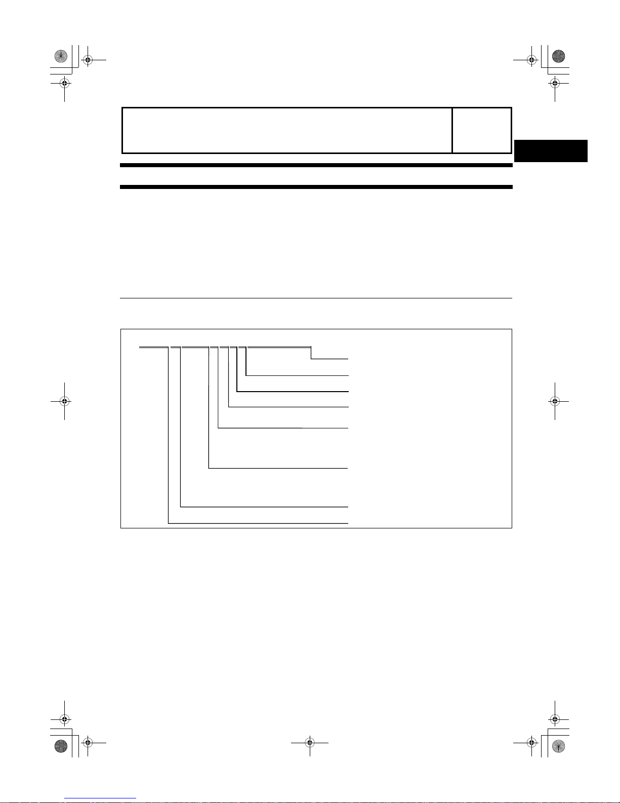
Efficient Replacement of Body Panels
• This section contains information on the body panels in regard to the welding types, number of spot welds, and
cut-and-join locations that are necessary for panel removal and installation.
• The type of weld and position are indicated by symbols.
• Some sections have notes concerning the operation being performed. Thoroughly read and understand the
notes before carrying out any procedures.
Example
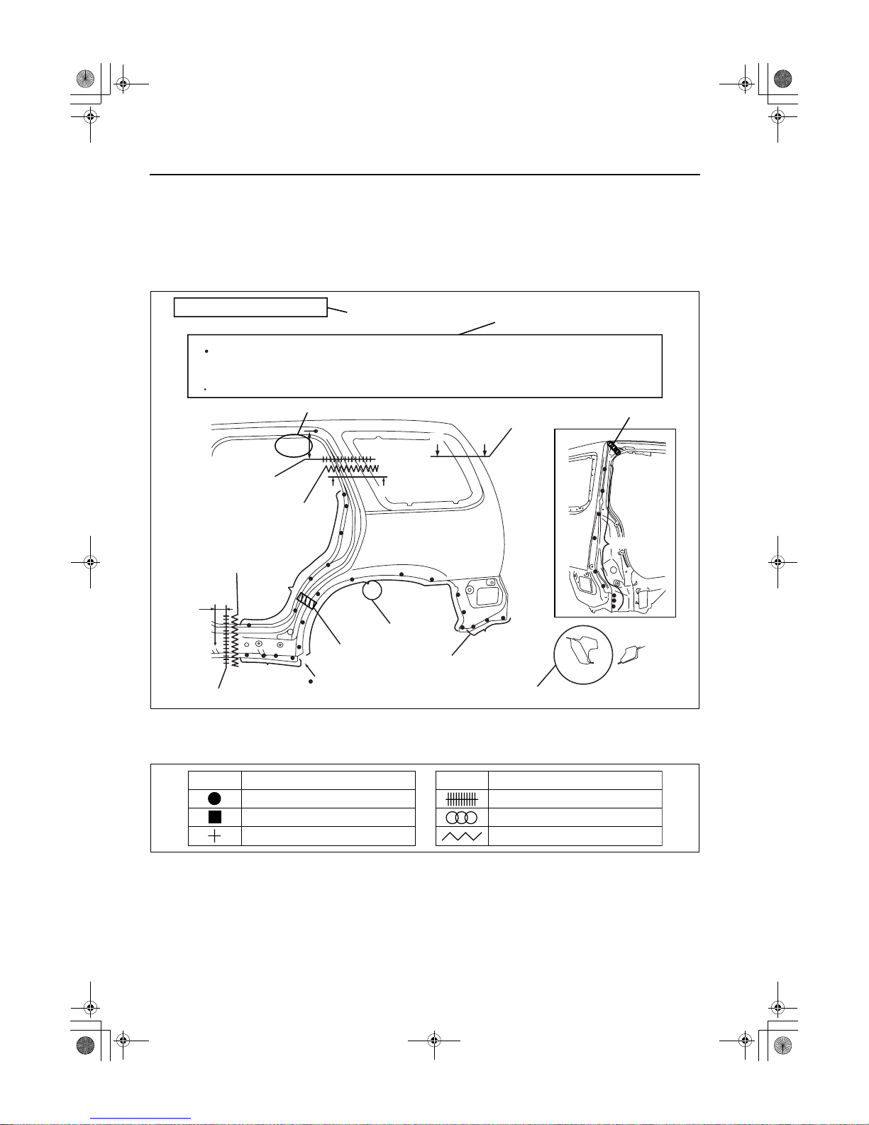
Symbols of Panel Replacement
• The following 6 symbols are used to indicate the type of weld that is used when replacing body panels.
REAR FENDER PANEL REMOVAL
Shows operation section
Shows procedure, caution and note
BRAZE WELDING
CUT-AND-JOINT LOCATION
CUT-AND-JOINT LOCATION
ROUGH CUT LOCATION
ROUGH CUT LOCATION
Shows number of weld
Shows welding region
Shows a cross
Shows a insulator
Shows a dimensions
Shows a cross location
Avoid cutting with a flame as the insulator (shaded) is flammable.
1.The rear fender panel and wheel house are joined with glue at the wheel arch line.
Drill the 24 weld locations indicated by (A), from the room side.
Caution
NOTE
BOTTOM SIDE 1
{9.84in}
250mm
(A)24
19
17
A-A
A
A
B-B
30mm
BB
{1.18in}
8
4
atraab00000001
SYMBOL
MEANING
Spot welding
CO
2
arc welding (plug welding)
CO
2
spot welding
SYMBOL
MEANING
Continuous MIG welding (Cut-and-join location)
Braze welding
Rough cut location
acxuub00000032
GENERAL INFORMATION
00-00–3
00
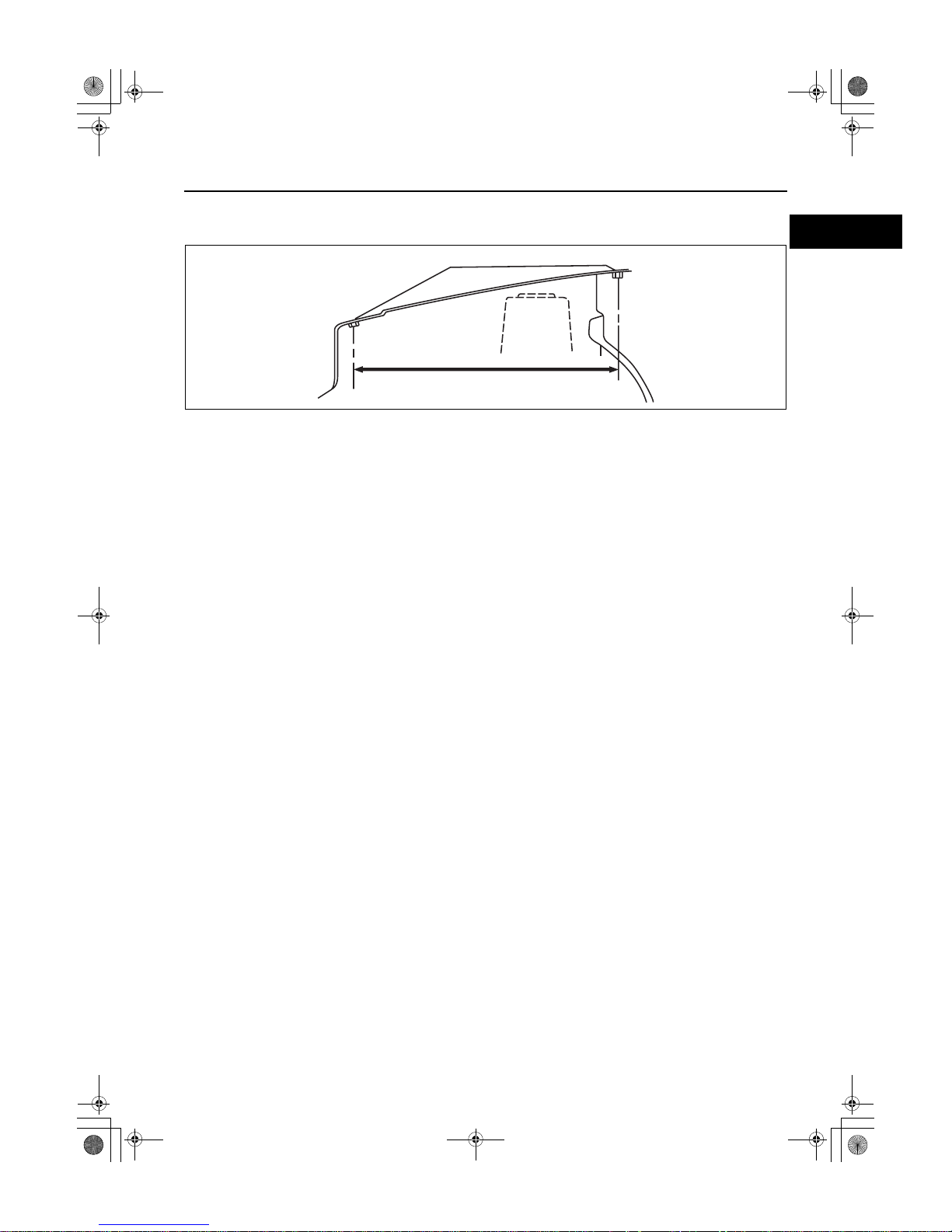
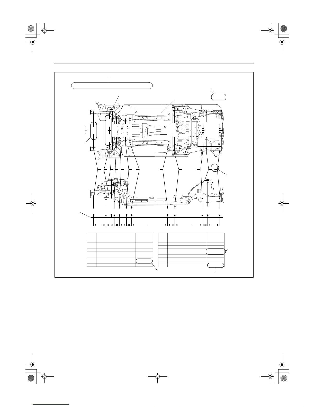
Body Dimensions (Flat-plane Dimensions)
• Flat-plane dimensions are the dimensions measured by projecting certain reference points onto a plane
surface.
• When there are no specific indications, the standard points and dimensions are symmetrical in regard to the
center of the vehicle.
• The hypothetical lines may differ according to the vehicle model.
• The schematic diagram shows the vehicle as it is projected from the underbody.
810
{31.89}
FLAT-PLANE DIMENSIONS
FRONT FENDER INSTALLATION NUT
acxuub00000033
00-00–4
GENERAL INFORMATION
Example
Shows vehicle section
When there are no specific indications, all of
units are in millimeters (mm).
Shows outline drawing
Shows dimension
The dimensions on the left
and right in regard to the center
of the vehicle are different.
Shows hypothetical
standard line
Shows point
symbol
Point
symbol
Designation
Hole diameter
or bolt or nut
size mm {in}
Crossmember No,1 standard
hole
Front side frame standard hole
Front suspension mounting
block surface hole center
Front suspension mounting
bolt
Front frame rear standard hole
Front frame rear standard hole
Rear side frame standard hole
Link bracket
Rear suspension housing
A
B
C
D
E
F
G
H
I
J
K
Rear side frame standard hole
Rear side frame standard hole
Shows bolt size
Shows hole diameter
Shows
slot
mm {in}
UNDERBODY FLAT-PLANE DIMENSIONS
φ 16 {0.62}
φ 16 {0.62}
φ 16 {0.62}
M14 {0.55}
φ 80 {3.14}
Point
symbol
Designation
Hole diameter
or bolt or nut
size mm {in}
φ 16 {0.62}
φ 31 {1.22}
φ 12 {0.47}
Rear suspension housing
L
φ 12 {0.47}
φ 16 {0.62}
φ 18 {0.62}
17 × 29.5
{0.66×1.16}
ABCDE F G H I J KL
1,016
{40.00}
687
{27.05}
420
182 93 144 120
{7.17} {3.66} {5.67} {4.72}
1,030
140
760
68
{5.51} {2.68}
379
{16.54}
{40.55}
{29.92} {14.92}
{25.75}
654
1,084 {42.84}
579
{22.80}
479
{18.86}
436
436
{17.17}
{17.17}
445
512
660
1,043
666
{17.52}
{20.16}
{25.98}
{41.06}
{26.22}
1,106 {43.54}
1,164
543
485
484
{21.37}
{19.05}
478
1,073 {37.91}
455
{17.91}
469
{18.46}
760
605
650
650
{29.92}
{23.82}
{25.59}
{25.59}
650
{45.83}
{25.59}
LH
RH
acxuub00000034
GENERAL INFORMATION
00-00–5
00
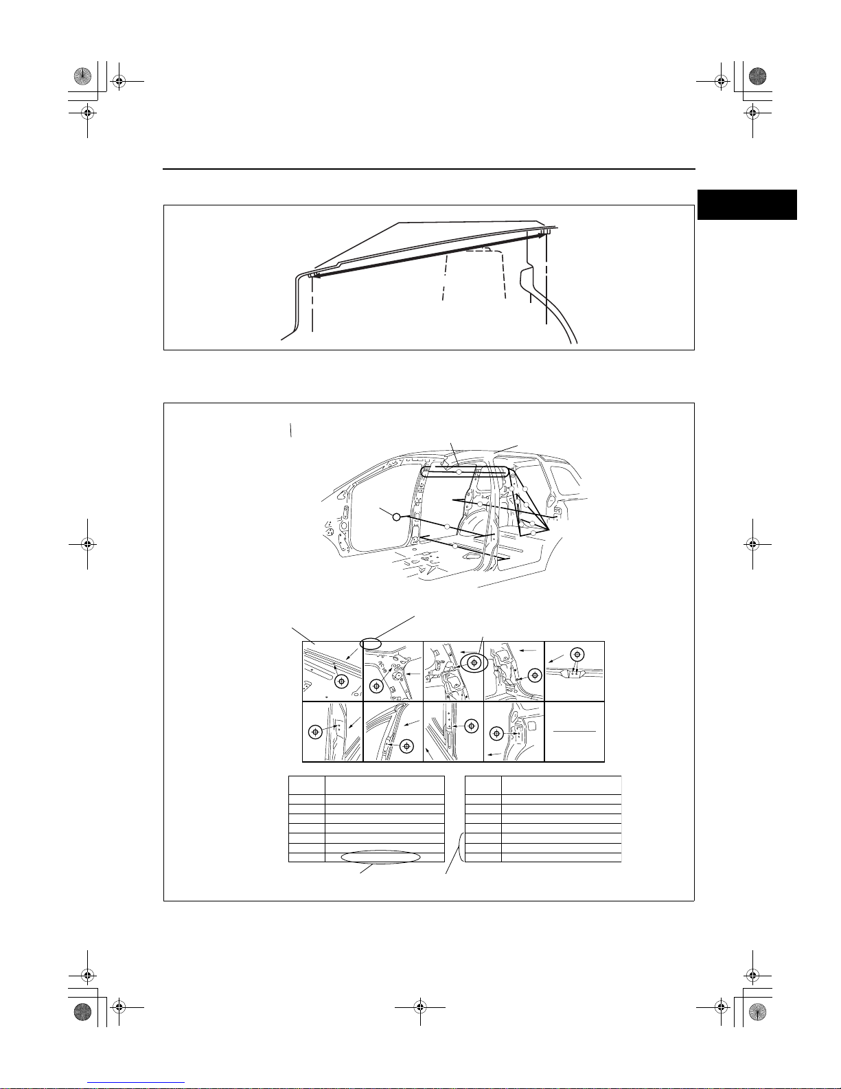
Body Dimensions (Straight-line Dimensions)
• Straight-line dimensions are the actual dimensions between two standard points.
• When there are no specific indications, the standard points and dimensions are symmetrical in regard to the
center of the vehicle.
Example
817
FRONT FENDER INSTALLATION NUT
STRAIGHT-LINE DIMENSIONS
{32.17}
acxuub00000035
ROOM STRAIGHT-LINE DIMENSIONS (2)
Shows vehicle section
Shows dimension location
Shows outline drawing
C
D
A
G
Shows point
symbol
Shows point indication
Without apostrophe:RH
With apostrophe:LH
Shows details of the standard
point location
Shows position and shape of the points
Shows dimension
No indication are shown within the
outline drawing.
A
Fr
Fr
Fr
Fr
Fr
Fr
Fr
Fr
Fr
Measured
location
Dimension mm {in}
1
2
3
4
5
6
7
1,184 {46.61}
1,064 {41.89}
919 {36.18}
690 {27.17}
1,185 {46.65}
901 {35,47}
607 {23.90}
Measured
location
Dimension mm {in}
8
9
10
11
B-B'
C-C'
D-D'
1,667 {65.63}
1,672 {65.83}
1,037 {40.83}
1,290 {50.79}
1,208 {47.56}
1,463 {57.60}
1,642 {64.65}
B-B
,
C-C
,
D-D
,
H-H
,
G-G
,
F-F
,
E-E
,
H
,
E. E
,
H
I
B
F
,
I - I
,
1
5
6
9
7
3
2
4
8
F
11
10
atraab00000002
00-00–6
GENERAL INFORMATION
Symbols of Body Dimensions
• The following 8 symbols are used to indicate the standard points.
End Of Sie
SERVICE PRECAUTIONS
id000000600200
Arrangement of Workshop
• Arrangement of the workshop is important for safe and efficient work.
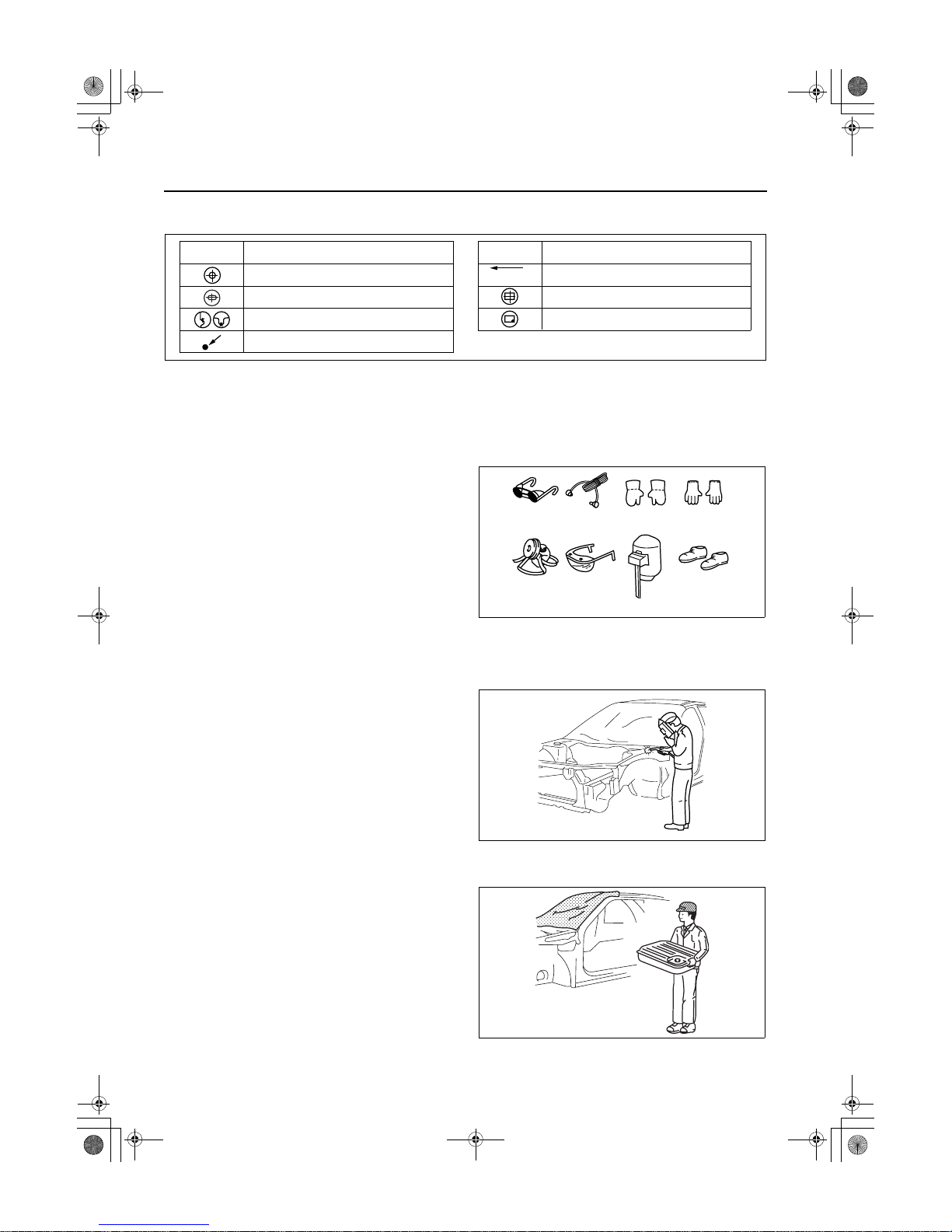
Safety Precautions
• Protective head covering and safety shoes should
always be worn. Depending upon the nature of
the work, gloves, safety glasses, ear protectors,
face shield, etc., should also be used.
Vehicle Protection
• Use seat covers and floor covers.
• Use heat-resistant protective covers to protect glass areas and seats from heat or sparks during welding.
• Protect items such as moldings, garnishes, and
ornaments with tape when welding.
Remove Dangerous Articles
• Remove the fuel tank before using an open flame
in that area. Plug connection piping to prevent
fuel leakage.
SYMBOL
MEANING
SYMBOL
MEANING
Center of circular hole
Center elliptical hole
Notch
Panel seam, bead, etc.
Bolt tip
(arrow only)
Center of rectangular-shaped hole
Edge of rectangular-shaped hole
acxuub00000037
Welding
glasses
Ear
protectors
Weldlng
gloves
Cotton
gloves
Dust mask Safety glasses
Face shield
Safety shoes
acxuub00000038
acxuub00000063
acxuub00000064
GENERAL INFORMATION
00-00–7
00
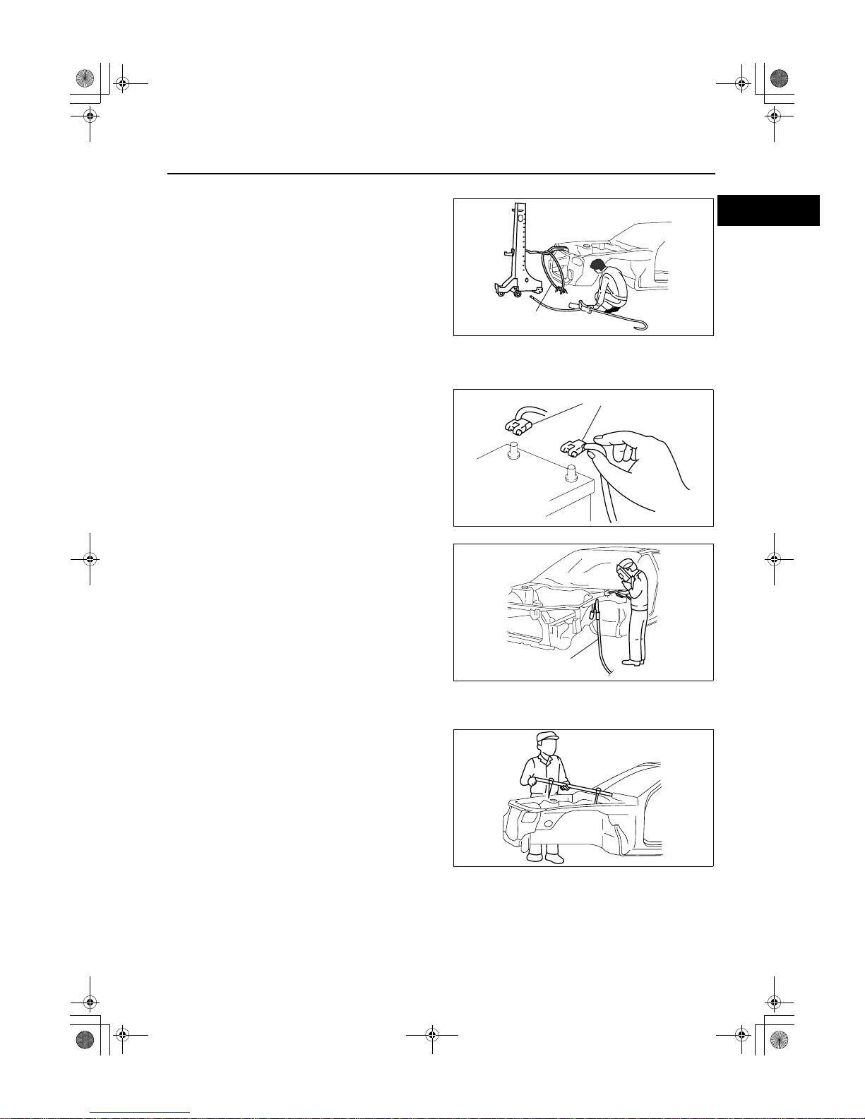
Use of Pulling Equipment
• When using pulling equipment, keep away from
the pulling area and use safety wires to prevent
accidents.
Prevent Short Circuits
• Turn the ignition switch to the LOCK position.
• Disconnect the battery cables.
• Securely connect the welding machine ground
near the welding area.
End Of Sie
EFFICIENT REMOVAL OF BODY PANELS
id000000600300
Body Measurements
• Before removal or rough-cutting, first measure the
body at and around the damaged area against
the standard reference dimension specifications.
If there is deformation, use frame repair
equipment to make a rough correction.
Safety wires
acxuub00000041
Battery cable
acxuub00000042
Ground
acxuub00000043
acxuub00000065
00-00–8
GENERAL INFORMATION
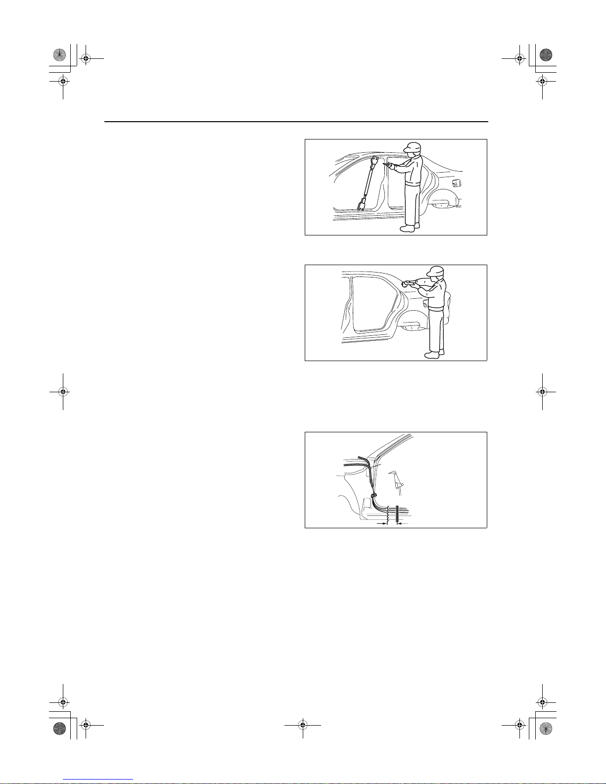
Prevention of Body Deformation
• Use a clamp or a jack for removal and reinforce at
and around the rough-cutting location to prevent
deforming of the body.
Selection of Cut-and-join Locations
• For parts where complete replacement is not
feasible, careful cutting and joining operations
should be followed. If the location to be cut is a
flat area where there is no reinforcement, the
selected cutting location should be where the
welding distortion will be minimal.
Removal of Associated Parts
• Protect moldings, garnishes, and ornaments with tape when removing associated parts.
Rough Cutting of Damaged Panel
• Verify that there are no parts (such as pipes, hoses, and wiring harness) nearby or on the opposite side of a
panel which could be damaged by heat.
• For cut-and-join areas, allow for an overlap of
30—50 mm {1.18—1.97 in} and then rough-cut
the damaged panel.
End Of Sie
acxuub00000066
acxuub00000067
Wiring harness
Rough cut location
Cut-and-join location
acxuub00000047

GENERAL INFORMATION
00-00–9
00
INSTALLATION PREPARATIONS
id000000600400
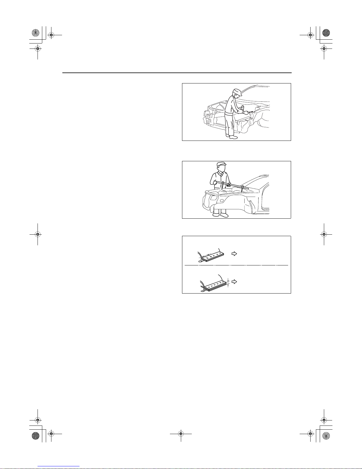
Rough Cutting of New Parts
• For cut-and-join areas, allow for an overlap of
30—50 mm {1.18—1.97 in} with the remaining
area on the body side and then rough-cut the new
parts.
Determination of Welding Method
• If the total thickness at the area to be welded is 3
mm {0.12 in} or more, use a CO2 gas
shielded-arc welder to make the plug welds.
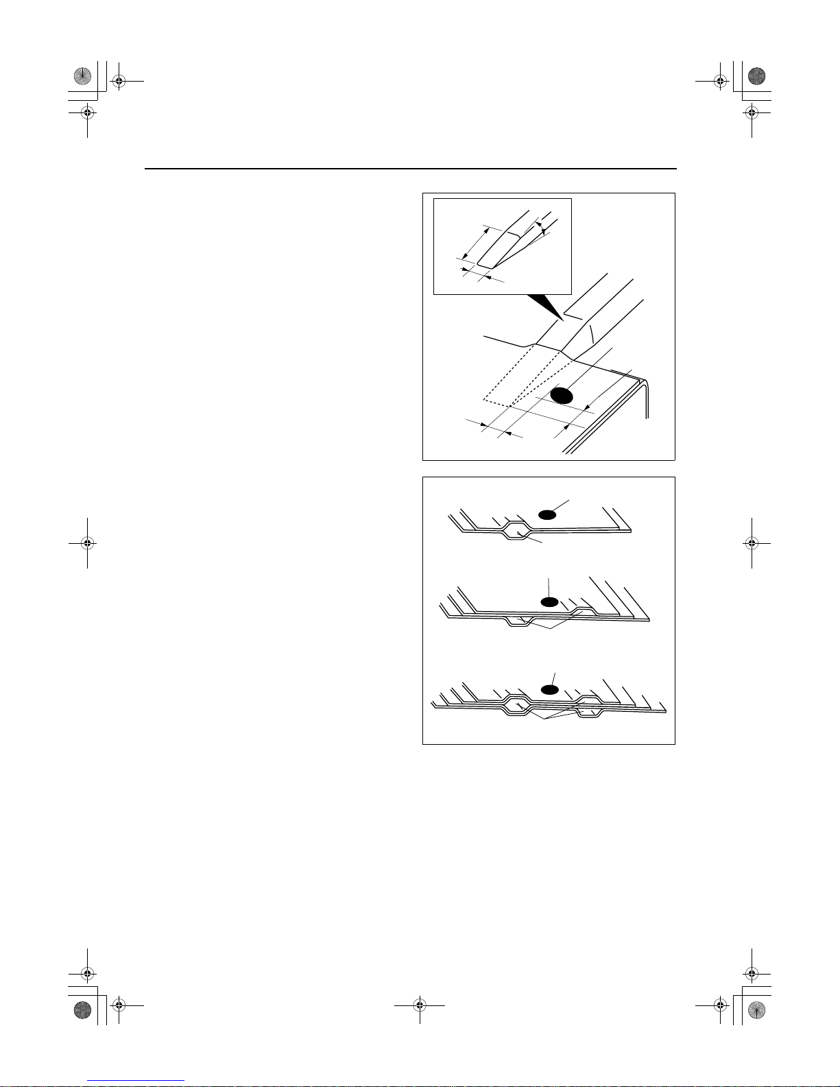
Making Holes for CO
2
Arc Welding
• For places that cannot be spot welded, make a hole for CO
2
arc welding using a punch or drill as follows.
(mm {in})
• Grind the shaded section indicated in the diagram
below and create a hole in the part where the 3—
4 plates are put together. Also, weld the plates
together tightly so that gaps do not develop.
Over lap
Over lap
Body side rough cut location
New part rough cut location
30-50mm{1.18-1.97in}
30-50mm{1.18-1.97in}
acxuub00000048
3mm
{0.12in}or more
acxuub00000049
Panel thickness (ø) Hole diameter (ø)
0.60—0.90 {0.02—0.03} 5 {0.19}
0.91—1.20 {0.04—0.05} 6 {0.23}
1.21—1.80 {0.051—0.07} 8 {0.31}
1.81—4.50 {0.071—0.17} 10 {0.39}
φ
10mm{0.39in}
Outer panel
Middle panel
Inner panel
30°
30°
acxuub00000050
00-00–10
GENERAL INFORMATION
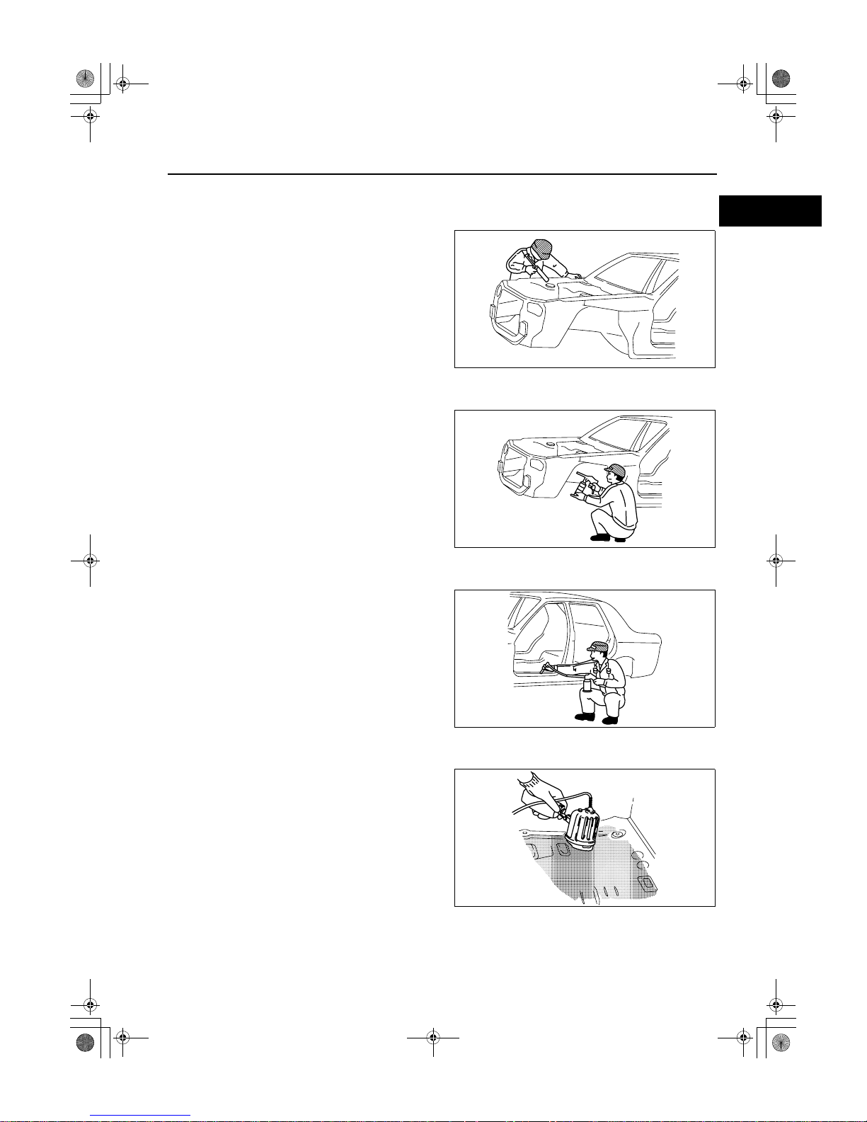
Application of Weld-through Primer
• For treatment against corrosion, remove the paint
grease, and other material from the portion of
new part and body to be welded, and apply
weld-through primer.
End Of Sie
EFFICIENT INSTALLATION OF BODY PANELS
id000000600500
Checking Preweld Measurements And Watching
• Align to the standard reference dimensions,
based upon the body dimensions illustration, so
that new parts are installed in the correct position.
Welding Notes
• For the number of weld points, welding should be
performed in accordance with the following
reference standards.
acxuub00000068
acxuub00000069
Spot welding
Original weld
If 3mm
{0.12in} or more
Original number of
welds x 1.3 or more
CO2 arc welding
Original spot weld
Repair weld
Repair weld
Original number of welds
or more
acxuub00000053

GENERAL INFORMATION
00-00–11
00
Spot Welding Notes
• The shape of the spot welder tip is D=(2×t)+3. If
the upper panel thickness is different from that of
the under panel, adjust to the thinner one.
• Because the weld strength is affected by the
shape of the spot welder tip, the optimum
condition of the tip should always be maintained.
• Spot welds should be made at points other than
the originally welded points.
• Before spot welding, make a trial weld using the
same material as the body panel to check the
weld strength.
D
70 - 120°
t
acxuub00000054
acxuub00000070
Test piece method
Nugget diameter
:4/5 of tip
acxuub00000071
00-00–12
GENERAL INFORMATION
Checking Weld Strength
• Installation locations of the engine, chassis, and
seat belts are designated as important safety
locations for weld strength. Check weld strength
by driving a chisel between the panels at every
fourth or fifth weld spot, and every tenth regular
weld location.
• Drive the chisel between the panels according to
the number of panels as shown below.
• To determine weld strength, drive the chisel
between the panel and check whether the panels
come apart. If the panels come apart, make
another weld near the original weld.
• Restore the shape of the checked area.
End Of Sie
Chisel dimensions
25mm
{0.98in}
8mm{0.31in}
{0.20in}
{0.20in}
20°
Weld location
Within 5mm
Within 5mm
acxuub00000057
Two panels
Weld location
Three panels
Weld location
One location
Two location
Four panels
Weld location
Three location
acxuub00000058
GENERAL INFORMATION
00-00–13
00
ANTICORROSION, SOUND INSULATION, AND VIBRATION INSULATION
id000000600600
Body Sealing
• Apply body sealer where necessary.
• For locations where application of body sealer is
difficult after installation, apply it before
installation.
Application of Undercoating
• Apply an undercoat to the required location of the
body.
Application of Rust Inhibitor
• Apply rust inhibitor (wax, oil, etc.) to the back of
the welded areas.
Application of Floor Silencer
• Apply floor silencer by heating with an infrared ray
lamp.
End Of Sie
acxuub00000059
acxuub00000060
acxuub00000061
acxuub00000062
00-00–14
GENERAL INFORMATION
ABBREVIATION
id000000600700
End Of Sie
CM Control module
Ctr Center
DSC Dynamic stability control
Fr Fron t
HU Hydraulic unit
LH Left
M Metallic
MC Mica
RH Right
Rr Rear
09-80A–1
09
BODY & ACCESSORIES
SECTION
80A
To c of S CT
BODY STRUCTURE
[CONSTRUCTION] . . . . . . . . 09-80A
BODY STRUCTURE[PANEL
REPLACEMENT]. . . . . . . . . . 09-80B
BODY STRUCTURE
[WATER-PROOF AND RUST
PREVENTIVE] . . . . . . . . . . . . 09-80C
BODY STRUCTURE
[DIMENSIONS] . . . . . . . . . . . . 09-80D
BODY STRUCTURE
[PLASTIC BODY PARTS]. . . . 09-80E
BODY STRUCTURE
[PRIMARY COLOR MIXTURE
CHART FOR
BODY COLOS] . . . . . . . . . . . . 09-80F
To c of S CT
09-80A BODY STRUCTURE [CONSTRUCTION]
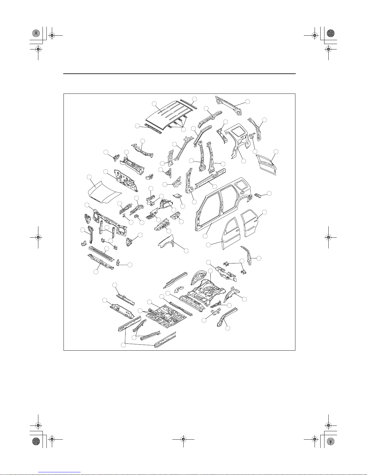
BODY COMPONENTS CONSTRUCTION
[CONSTRUCTION] . . . . . . . . . . . . . . . . 09-80A–2
End of Toc
BM: CONSTRUCTION
09-80A–2
BODY STRUCTURE [CONSTRUCTION]
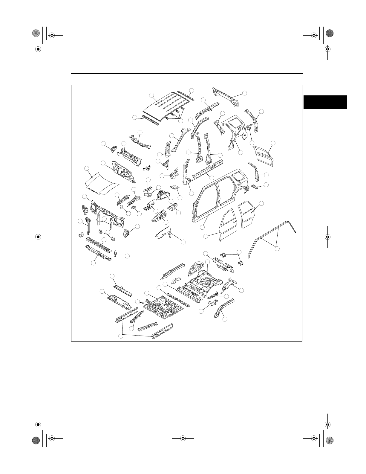
BODY COMPONENTS CONSTRUCTION[CONSTRUCTION]
id098007739700
R.H.D. MODELS
.
9
8
7
5
4
3
1
2
10
6
19
18
17
15
16
14
13
11
12
20
28
27
29
25
26
24
23
21
22
30
39
38
37
35
36
34
33
31
32
40
63
62
61
60
58
59
64
65
47
45
46
44
43
41
42
48
57
56
55
53
54
52
51
49
50
atraab00000004
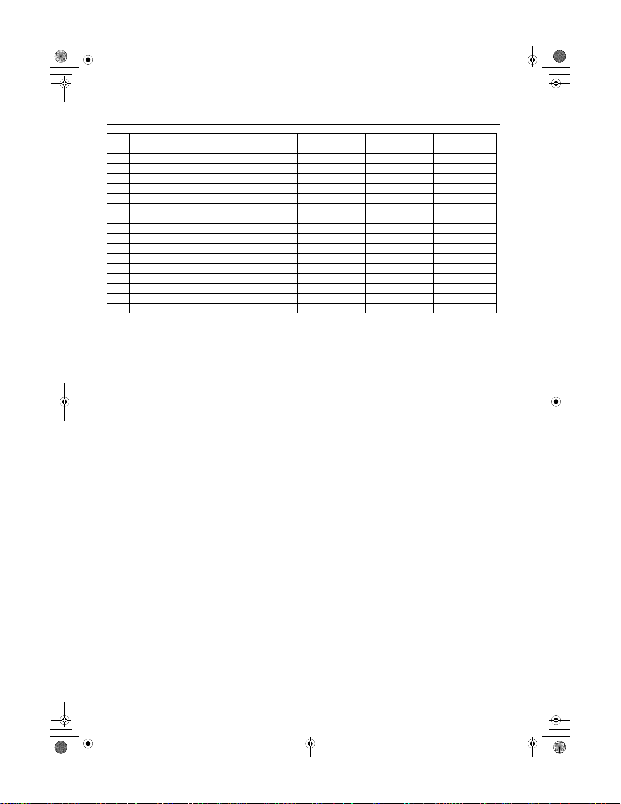
BODY STRUCTURE [CONSTRUCTION]
09-80A–3
80A
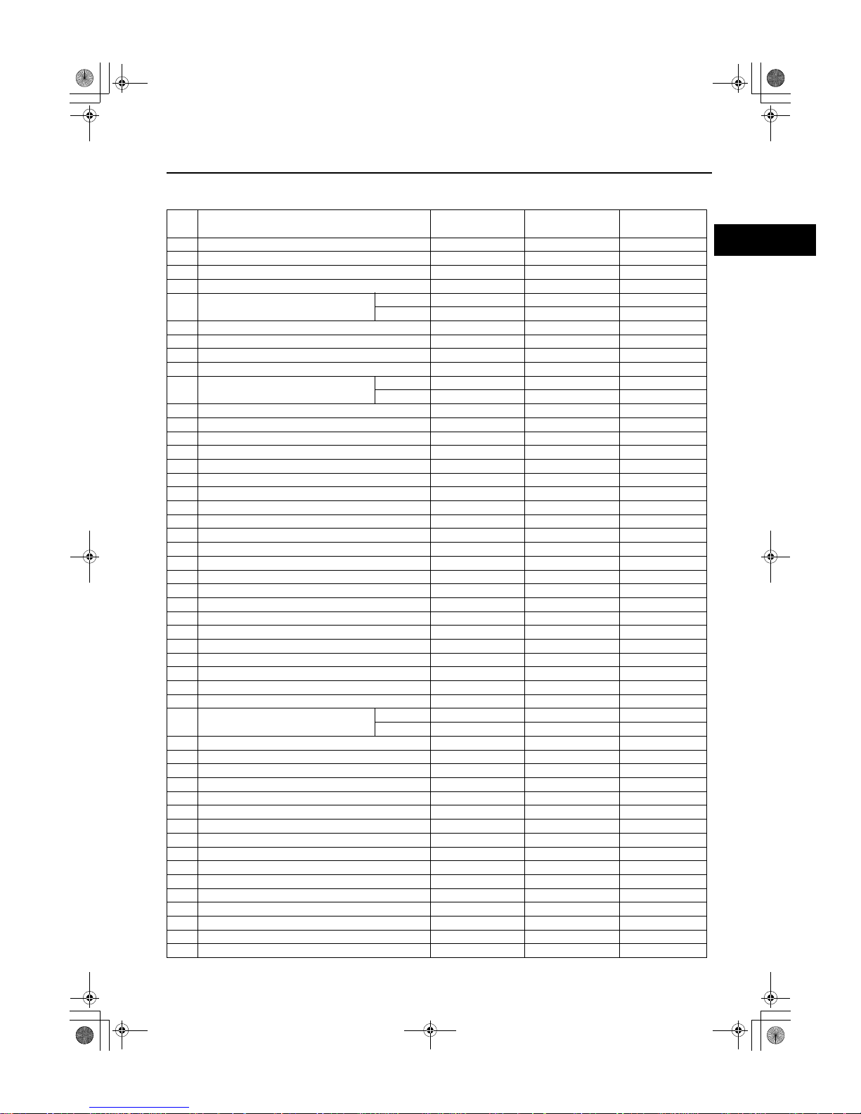
x:Applied
-:Not applied
No. Part Name High- tension steel Rust proof steel
Thickness
(mm) {in}
1 Bonnet x x 0.70 {0.028}
2 Shroud upper panel - - 0.90 {0.035}
3 Lamp bracket - x 1.20 {0.047}
4 Shroud side stay x x 1.20 {0.047}
5 Front bumper bracket
RH x - 2.00 {0.079}
LH x - 2.30 {0.091}
6 Bonnet lock stay - x 1.00 {0.039}
7 Crossmember No.1 (front) - x 1.00 {0.039}
8 Crossmember No.1 (rear) - x 1.00 {0.039}
9 Cross side reinforcement x x 2.30 {0.091}
10 Hook reinforcement
RH x - 2.00 {0.079}
LH x - 1.40 {0.055}
11 Front side frame (outer) x x 1.60 {0.063}
12 Frame reinforcement - x 1.40 {0.055}
13 Front side frame (inner) x x 1.60 {0.063}
14 Apron reinforcement (front) - - 1.00 {0.039}
15 Wheel apron panel (front) - x 0.70 {0.028}
16 Apron reinforcement - - 0.80 {0.031}
17 Suspension housing (upper) x x 2.90 {0.114}
18 Torque box - x 1.20 {0.047}
19 Front frame (rear) - x 2.30 {0.091}
20 Dash lower panel - - 0.75 {0.030}
21 Cowl upper plate x x 1.20 {0.047}
22 Dash upper panel - - 0.70 {0.028}
23 Cowl panel - x 0.70 {0.028}
24 Torque box reinforcement - x 1.20 {0.047}
25 Cowl side reinforcement - x 1.40 {0.055}
26 Cowl side panel - x 0.70 {0.028}
27 Hinge pillar (inner) - - 1.00 {0.039}
28 Hinge pillar reinforcement x x 1.20 {0.047}
29 Front pillar (inner) x - 1.00 {0.039}
30 Side sill reinforcement - x 1.00 {0.039}
31 Center pillar reinforcement x - 1.60 {0.063}
32 Center pillar (inner) - - 1.20 {0.047}
33 Front pillar reinforcement
RH x - 2.00 {0.079}
LH x - 1.40 {0.055}
34 Roof rail (inner) x - 1.00 {0.039}
35 Rear pillar (inner) - x 0.65 {0.026}
36 C-pillar reinforcement x - 1.00 {0.039}
37 Corner plate - x 1.00 {0.039}
38 Rear pillar reinforcement - - 0.80 {0.031}
39 Rear end panel - - 0.70 {0.028}
40 Front header - - 0.70 {0.028}
41 Roof panel - - 0.75 {0.030}
42 Roof reinforcement - - 0.80 {0.031}
43 Rear header - - 0.70 {0.028}
44 Front fender panel x x 0.70 {0.028}
45 Side frame (outer) - x 0.70 {0.028}
46 Rear end side member - x 0.80 {0.031}
47 Rear pillar (outer) - x 0.80 {0.031}
48 Front door x x 49 Rear door x x -
09-80A–4
BODY STRUCTURE [CONSTRUCTION]
50 Side sill (inner) x x 2.00 {0.079}
51 Front B frame x x 1.40 {0.055}
52 Crossmember No.3 - - 2.00 {0.079}
53 Crossmember No.4 x x 1.40 {0.055}
54 Crossmember No.2 - - 0.80 {0.031}
55 Front floor pan - - 0.80 {0.031}
56 Crossmember No.2.5 - - 0.80 {0.031}
57 Crossmember No.3 (upper) - - 0.80 {0.031}
58 Seat bracket - - 0.70 {0.028}
59 Rear side frame x x 1.40 {0.055}
60 Hook bracket x x 1.20 {0.047}
61 Wheel house panel - x 0.70 {0.028}
62 Rear floor pan - - 0.65 {0.026}
63 Crossmember No.5 - - 0.65 {0.026}
64 Rear bumper bracket x x 1.40 {0.055}
65 Liftgate - x -
No. Part Name High- tension steel Rust proof steel
Thickness
(mm) {in}
BODY STRUCTURE [CONSTRUCTION]
09-80A–5
80A
L.H.D. MODELS
.
9
8
7
5
4
3
1
2
10
6
19
18
17
15
16
14
13
11
12
20
28
27
29
25
26
24
23
21
22
30
39
38
37
35
36
34
33
31
32
40
63
62
61
60
58
59
64
66
47
45
46
44
43
41
42
48
65
57
56
55
53
54
52
51
49
50
atraab00000005
09-80A–6
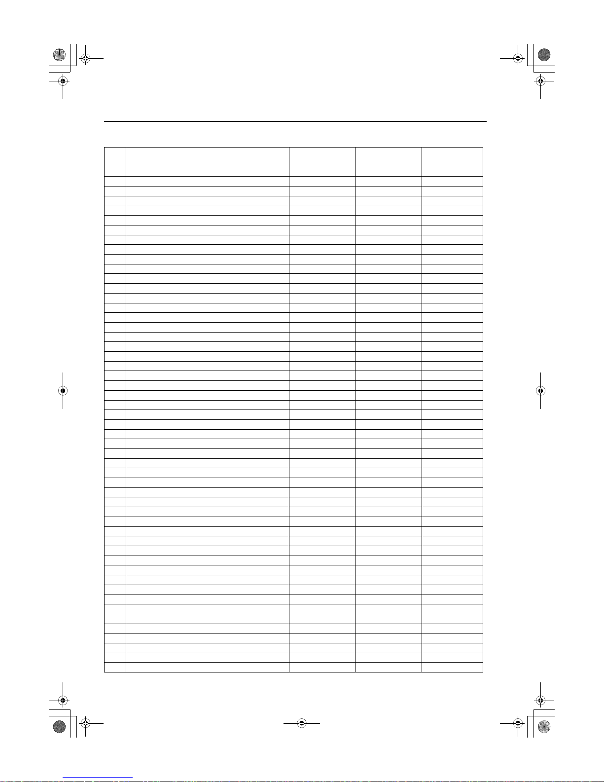
BODY STRUCTURE [CONSTRUCTION]
x:Applied
-:Not applied
No. Part Name High- tension steel Rust proof steel
Thickness
(mm) {in}
1 Bonnet x x 0.70 {0.028}
2 Shroud upper panel - x 0.90 {0.035}
3 Lamp bracket - x 1.20 {0.047}
4 Shroud side stay x x 1.20 {0.047}
5 Front bumper bracket x - 2.30 {0.091}
6 Bonnet lock stay - x 1.00 {0.039}
7 Crossmember No.1 (front) - x 1.00 {0.039}
8 Crossmember No.1 (rear) - x 1.00 {0.039}
9 Cross side reinforcement x - 2.30 {0.091}
10 Hook reinforcement x - 1.40 {0.055}
11 Front side frame (outer) x x 1.60 {0.063}
12 Frame reinforcement - x 1.40 {0.055}
13 Front side frame (inner) x x 1.60 {0.063}
14 Apron reinforcement (front) - x 1.00 {0.039}
15 Wheel apron panel (front) - x 0.70 {0.028}
16 Apron reinforcement - x 0.80 {0.031}
17 Suspension housing (upper) x x 2.60 {0.102}
18 Torque box - x 1.20 {0.047}
19 Front frame rear - x 2.30 {0.091}
20 Dash lower panel - x 0.75 {0.030}
21 Cowl upper plate x x 1.20 {0.047}
22 Dash upper panel - x 0.70 {0.028}
23 Cowl panel - x 0.70 {0.028}
24 Torque box reinforcement - x 1.20 {0.047}
25 Cowl side reinforcement - - 1.40 {0.055}
26 Cowl side panel - x 0.70 {0.028}
27 Hinge pillar (inner) - - 1.00 {0.039}
28 Hinge pillar reinforcement x x 1.20 {0.047}
29 Front pillar (inner) x - 1.00 {0.039}
30 Side sill reinforcement - x 1.00 {0.039}
31 Center pillar reinforcement x - 1.60 {0.063}
32 Center pillar (inner) - - 1.20 {0.047}
33 Front pillar reinforcement x - 1.40 {0.055}
34 Roof rail (inner) x - 1.00 {0.039}
35 Rear pillar (inner) - x 0.70 {0.028}
36 C-pillar reinforcement x - 1.00 {0.039}
37 Corner plate - x 1.00 {0.039}
38 Rear pillar reinforcement - - 0.80 {0.031}
39 Rear end panel - - 0.70 {0.028}
40 Front header - - 0.70 {0.028}
41 Roof panel - - 0.75 {0.030}
42 Roof reinforcement - - 0.80 {0.031}
43 Rear header - - 0.70 {0.028}
44 Front fender panel x x 0.70 {0.028}
45 Side frame (outer) - x 0.70 {0.028}
46 Rear end side member - x 0.80 {0.031}
47 Rear pillar (outer) - x 0.80 {0.031}
48 Front door x x 49 Rear door x x 50 Side sill (inner) x x 2.00 {0.079}
51 Front B frame x x 1.40 {0.055}
52 Crossmember No.3 - - 2.00 {0.079}

BODY STRUCTURE [CONSTRUCTION]
09-80A–7
80A
End Of Sie
53 Crossmember No.4 x x 1.40 {0.055}
54 Crossmember No.2 - - 0.80 {0.031}
55 Front floor pan - x 0.65 {0.026}
56 Crossmember No.2.5 - - 0.80 {0.031}
57 Crossmember No.3 (upper) - - 0.80 {0.031}
58 Seat bracket - - 0.70 {0.028}
59 Rear side frame x x 1.40 {0.055}
60 Hook bracket x x 1.20 {0.047}
61 Wheel house panel - x 0.70 {0.028}
62 Rear floor pan - x 0.65 {0.026}
63 Crossmember No.5 - x 0.65 {0.026}
64 Rear bumper bracket x - 1.40 {0.055}
65 Rain rail - x 0.70 {0.028}
66 Liftgate - x -
No. Part Name High- tension steel Rust proof steel
Thickness
(mm) {in}

BODY STRUCTURE [PANEL REPLACEMENT]
09-80B–1
80B
09-80B BODY STRUCTURE [PANEL REPLACEMENT]
RADIATOR SHROUD PANEL
COMPONENT REMOVAL
[PANEL REPLACEMENT]. . . . . . . . . . . 09-80B–2
RADIATOR SHROUD PANEL
COMPONENT INSTALLATION
[PANEL REPLACEMENT]. . . . . . . . . . . 09-80B–2
CROSSMEMBER No.1 REMOVAL
[PANEL REPLACEMENT]. . . . . . . . . . . 09-80B–3
CROSSMEMBER No.1 INSTALLATION
[PANEL REPLACEMENT]. . . . . . . . . . . 09-80B–3
APRON REINFORCEMENT AND COWL
SIDE REINFORCEMENT REMOVAL
[PANEL REPLACEMENT]. . . . . . . . . . . 09-80B–4
APRON REINFORCEMENT AND COWL
SIDE REINFORCEMENT
INSTALLATION[PANEL
REPLACEMENT]. . . . . . . . . . . . . . . . . . 09-80B–5
WHEEL APRON PANEL
COMPONENT REMOVAL
[PANEL REPLACEMENT]. . . . . . . . . . . 09-80B–6
WHEEL APRON PANEL COMPONENT
INSTALLATION[PANEL
REPLACEMENT]. . . . . . . . . . . . . . . . . . 09-80B–7
FRONT SIDE FRAME COMPONENT
REMOVAL[PANEL
REPLACEMENT]. . . . . . . . . . . . . . . . . . 09-80B–8
FRONT SIDE FRAME COMPONENT
INSTALLATION[PANEL
REPLACEMENT]. . . . . . . . . . . . . . . . . . 09-80B–9
FRONT SIDE FRAME
(PARTIAL CUTTING) REMOVAL
[PANEL REPLACEMENT]. . . . . . . . . . . 09-80B–10
FRONT SIDE FRAME
(PARTIAL CUTTING) INSTALLATION
[PANEL REPLACEMENT]. . . . . . . . . . . 09-80B–11
FRONT FRAME (REAR) REMOVAL
[PANEL REPLACEMENT]. . . . . . . . . . . 09-80B–12
FRONT FRAME (REAR) INSTALLATION
[PANEL REPLACEMENT]. . . . . . . . . . . 09-80B–13
FRONT PILLAR REMOVAL[PANEL
REPLACEMENT]. . . . . . . . . . . . . . . . . . 09-80B–14
FRONT PILLAR INSTALLATION
[PANEL REPLACEMENT] . . . . . . . . . . . 09-80B–16
CENTER PILLAR REMOVAL
[PANEL REPLACEMENT] . . . . . . . . . . . 09-80B–18
CENTER PILLAR INSTALLATION
[PANEL REPLACEMENT] . . . . . . . . . . . 09-80B–19
SIDE SILL PANEL REMOVAL
[PANEL REPLACEMENT] . . . . . . . . . . . 09-80B–20
SIDE SILL PANEL INSTALLATION
[PANEL REPLACEMENT] . . . . . . . . . . . 09-80B–21
REAR FENDER PANEL REMOVAL
[PANEL REPLACEMENT] . . . . . . . . . . . 09-80B–22
REAR FENDER PANEL INSTALLATION
[PANEL REPLACEMENT] . . . . . . . . . . . 09-80B–23
REAR END PANEL AND
CROSSMEMBER No.5 REMOVAL
[PANEL REPLACEMENT] . . . . . . . . . . . 09-80B–24
REAR END PANEL AND
CROSSMEMBER No.5 INSTALLATION
[PANEL REPLACEMENT] . . . . . . . . . . . 09-80B–25
REAR PILLAR (OUTER) AND REAR
PILLAR REINFORCEMENT REMOVAL
[PANEL REPLACEMENT] . . . . . . . . . . . 09-80B–26
REAR PILLAR (OUTER) AND REAR
PILLAR REINFORCEMENT
INSTALLATION[PANEL
REPLACEMENT] . . . . . . . . . . . . . . . . . .09-80B–27
REAR FLOOR PAN REMOVAL
[PANEL REPLACEMENT] . . . . . . . . . . . 09-80B–28
REAR FLOOR PAN INSTALLATION
[PANEL REPLACEMENT] . . . . . . . . . . . 09-80B–29
REAR SIDE FRAME
(PARTIAL CUTTING) REMOVAL
[PANEL REPLACEMENT] . . . . . . . . . . . 09-80B–30
REAR SIDE FRAME
(PARTIAL CUTTING) INSTALLATION
[PANEL REPLACEMENT] . . . . . . . . . . . 09-80B–30
ROOF PANEL REMOVAL
[PANEL REPLACEMENT] . . . . . . . . . . . 09-80B–31
ROOF PANEL INSTALLATION[PANEL
REPLACEMENT] . . . . . . . . . . . . . . . . . .09-80B–32
End of Toc
BM: RADIATOR SHROUD PANEL
 Loading...