

Page 1
Evaporative Emission (EVAP) Canisters
SECTION 310-00: Fuel System 2004 Freestar/Monterey Workshop Manual
Page
1
of 82004 Freestar/Monterey Workshop Manual
10/9/2010
http://www.fordtechservice.dealerconnection.com/pubs/content/~WS4W/~MUS~LEN/20/
...
DIAGNOSIS AND TESTING
Procedure revision date: 07/31/ 2003
Evaporative Emissions
Printable View (184 KB)
Special Tool(s)
Worldwide Diagnostic System (WDS)
418-F224
New Generation STAR (NGS) Tester
418-F052, or equivalent scan tool
Evaporative Emission System Leak Tester
310-F007 (134-00056) or equivalent
The EVAP running loss system leak test:
utilizes intake manifold vacuum to test the system and involves several stages.
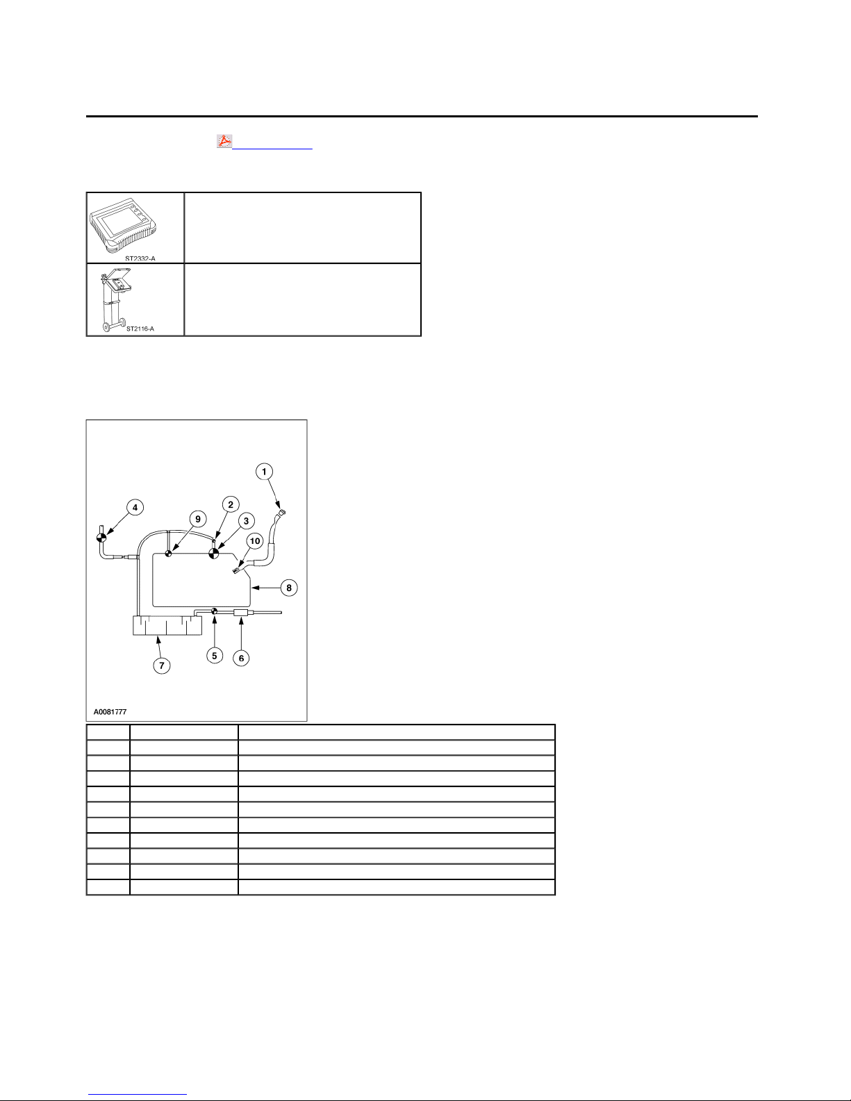
Evaporative Emission System
Item Part Number Description
1 9030 Fuel filler cap
2 9C052 Fuel tank pressure sensor
3 9B190 RIU limit vent valve
4 9C915 Evaporative emission canister purge valve
5 9F945 Canister vent solenoid
6 9B328 Evaporative emission dust separator
7 9D653 Evaporative emission canister
8 9002 Fuel tank
9 9B593 Fuel vapor vent valve
10 9189 Fuel filler pipe check valve
Principles of Operation
Evaporative Emission (EVAP) Canister Purge Valve
The EVAP canister purge valve is controlled by the powertrain control module (PCM). The EVAP canister purge valve controls the flow of fuel vapors from the EVAP
canisters to the engine intake manifold during various engine operating modes. The EVAP canister purge valve is normally closed.
Page 2
Fuel vapors from the fuel tank are stored in the EVAP canisters. When the engine is running, the vapors are purged from the EVAP canisters for combustion.
EVAP canisters or vent solenoid
Page
2
of 82004 Freestar/Monterey Workshop Manual
10/9/2010
http://www.fordtechservice.dealerconnection.com/pubs/content/~WS4W/~MUS~LEN/20/
...
Canister Vent Solenoid
During the Evaporative Emission Running Loss System Monitor Test, Evaporative Emissions Repair Verification Drive Cycle, and the Evaporative Emission System
Leak Test, the canister vent solenoid is closed to allow either a vacuum to be drawn on the fuel tank or to hold a specified pressure in the system. The canister vent
solenoid is normally open.
Fuel Tank Pressure (FTP) Sensor
The fuel tank pressure (FTP) sensor is used to measure the fuel tank pressure during the Evaporative Emissions Monitor Test. It is also used to control excessive fuel
tank pressures by forcing the EVAP system to purge. The fuel tank pressure sensor is mounted in the main vapor line.
Fuel Vapor Vent (FVV) Valve Assembly
The fuel vapor vent (FVV) valve assembly is mounted on the top of the fuel tank. It is used to control the flow of fuel vapors entering the EVAP system. The head portion
of the assembly prevents the fuel tank from overfilling during refueling. The assembly also has a spring float, which prevents liquid fuel from entering the vapor delivery
system under severe handling or vehicle rollover conditions. In the upright position, the open bottom of the float will lift and shut off the orifice. Under severe handling
conditions, the spring will push the float closed when angles allow liquid fuel to reach the orifice. In a rollover condition, the weight of the open bottom float and spring
pressure will close the orifice.
Fuel Filler Pipe Check Valve
The fuel filler pipe check valve is an integral part of the fuel tank or the fuel filler pipe. It is intended to prevent liquid fuel from re-entering the fuel filler pipe from the fuel
tank after refueling.
Fuel Filler Cap
The fuel filler cap is used to prevent fuel spill and to close the EVAP system to the atmosphere.
Fill Limit Vent Valve (FLVV)
The fill limit vent valve is mounted on top of the fuel tank. It has a main orifice which allows fuel vapor to route to the carbon canisters during refueling. This orifice is
controlled by a float, when the tank is full the flow of vapor is stopped and prevents the tank from overfilling.
Evaporative Emission (EVAP) System Monitor
When a fault occurs, the EVAP system monitor is reset to NO and a diagnostic trouble code (DTC) is set in the PCM memory. After the DTC is repaired, the vehicle
drive cycle must be completed to reset the monitor in preparation for inspection and maintenance testing.
EVAP Running Loss System Leak Test
To start the testing, conditions of stable purging and vehicle speed must be satisfied. During the first stage, the EVAP canister vent solenoid is closed, while the EVAP
canister purge valve remains open, applying and building vacuum in the system as indicated by the FTP sensor. This phase checks for major leaks in the EVAP system.
In the second stage, the EVAP canister purge valve closes and the system looks for minimal decay rate in the vacuum, indicating the absence of any small EVAP
system leaks.
The last stage is entered only if stage two of the leak test has failed and checks whether the failed test was due to excess vapor generation. It monitors fuel vapor
generation rate. Initially, the canister vent solenoid is opened to equalize EVAP system pressure to atmosphere. Then the canister vent solenoid is closed, allowing
pressure to build if vapor generation is present in sufficient quantity. If the rate of generation is found to be too high, the EVAP running loss system leak test is aborted.
If not, then a small leak is diagnosed.
Inspection and Verification
1. Verify the customer concern is with the evaporative emission (EVAP) system.
2. Visually inspect for the following obvious signs of mechanical damage.
Visual Inspection Chart
Mechanical
Fuel filler cap
EVAP test port
EVAP canister lines or hoses
Vacuum lines or hoses
3. If the concern remains after the inspection, connect the scan tool to the data link connector (DLC) located beneath the instrument panel and select the vehicle to
be tested from the scan tool menu. If the scan tool does not communicate with the vehicle:
check that the program card is correctly installed.
check the connections to the vehicle.
check the ignition switch position.
4. If the scan tool still does not communicate with the vehicle, refer to the scan tool manual.
5. Carry out the DATA LINK DIAGNOSTICS test. If the scan tool responds with:
CKT914, CKT915 or CKT70 = ALL ECUS NO RESP/N OT EQUIP, refer to Section 418-00.
NO RESP/NOT EQUIP for PCM, refer to the Powertrain Control/Emissions Diagnosis (PC/ED) manual.
Page 3

Page
3
of 82004 Freestar/Monterey Workshop Manual
10/9/2010
http://www.fordtechservice.dealerconnection.com/pubs/content/~WS4W/~MUS~LEN/20/
...
SYSTEM PASSED, retrieve and record the continuous diagnostic trouble codes (DTCs), erase the continuous DTCs and carry out the PCM KOEO selftest.
6. If the DTCs retrieved are related to the concern, go to the PCM Diagnostic Trouble Code (DTC) Index to continue diagnostics.
7. If the concern remains after the inspection, determine the symptom. GO to Symptom Chart.
PCM Diagnostics Trouble Code (DTC) Index
DTC Description Source Action
P0442
Small Leak Detected in EVAP Systema
P0457 Cap Off PCM GO to Pinpoint Test A.
P0456 Very Small Leak Detected in EVAP System PCM GO to Pinpoint Test A.
P0455 Major Leak or no Flow Detected PCM GO to Pinpoint Test B.
P1443 Very Small or no Purge Flow Detected PCM GO to Pinpoint Test B.
P1450 Excessive Vacuum Detected in the Fuel Tank PCM GO to Pinpoint Test C.
— Any Other PCM DTC PCM REFER to the Powertrain Control/Emissions Diagnosis (PC/ED) manual.
a
As small as 1.02 mm (0.040 in).
Symptom Chart
SYMPTOM CHART
Condition Possible Sources Action
Hissing sound when
removing fuel cap
Excessive fuel odor
Slow fuel fill
Canister vent solenoid.
Evaporative emissions canisters.
Fuel vapor control valve tube assembly.
EVAP canister tube.
EVAP canister purge outlet tube.
Canister vent solenoid.
Evaporative emissions canisters.
Fuel vapor control valve tube assembly.
Evaporative emissions test port.
EVAP canister purge outlet tube.
Restriction in the canister vent solenoid, dust filter, carbon canisters and
canister attachment hoses or vent tubing.
Restriction in the fuel fill hose or fuel fill pipe.
Pinpoint Tests
NOTE: Reinstall or install new evaporative emission hose clamps removed or damaged during testing procedures.
PINPOINT TEST A: DTC P0442 SMALL LEAK IN EVAP SYSTEM
NOTE: Condition P0442 DTC set: less than 0.625 kPa (2.5 inches H2O) bleed-up over 15 seconds at 75% fuel fill. Vapor generation limit: more than 0.625 kPa (2.5
inches H2O) over 120 seconds.
PCM GO to Pinpoint Test A.
GO to Pinpoint
Test D.
GO to Pinpoint
Test E.
GO to Pinpoint
Test C.
Test Step Result / Action to Take
A1 VISUALLY INSPECT THE COMPONENTS FOR
SMALL LEAKS
Check for the presence of a fuel filler cap. Do not
tighten or check for correct installation at this time.
Verify the canister vent solenoid is correctly seated
on the EVAP canister.
Check for cut or loose connections to fuel vapor
hoses, tubes and connections in the following
locations:
EVAP canisters to EVAP canister purge valve
EVAP canister to fuel vapor vent valve
assembly
Check the fuel filler pipe for damage.
Is a concern with a hose, tube, connection or
valve visually evident?
A2 CHECK AT THE EVAP TEST PORT FOR SMALL
SYSTEM LEAKS
Disconnect and plug the evaporative emission return
tube at the intake manifold.
Complete the evaporative emission system leak test.
Refer to Evaporative Emission System Leak Test in
this section.
Does the system pass the leak test?
A3 VISUALLY INSPECT THE FUEL FILLER CAP
Yes
REPAIR or INSTALL new components as necessary. GO to A2.
No
GO to A2.
Yes
GO to A3.
No
GO to A4.
Page 4

Page
4
of 82004 Freestar/Monterey Workshop Manual
10/9/2010
http://www.fordtechservice.dealerconnection.com/pubs/content/~WS4W/~MUS~LEN/20/
...
Visually inspect the fuel filler cap for damage.
Is the fuel filler cap damaged?
A4 CHECK FOR SMALL LEAKS AT THE FUEL FILLER
CAP AND EVAP TEST PORT
Connect the Evaporative Emission System Leak
Tester to the fuel filler pipe.
Key in ON position.
Close the canister vent solenoid. Refer to Canister
Vent Solenoid Closing Procedure in this section.
Pressurize the EVAP system to 3.48 kPa (14 inches
H2O).
Using the ultrasonic leak detector, check the fuel
filler cap and EVAP test port for leaks.
Is a leak detected?
A5 CHECK FOR CONCERN OTHER THAN THE FUEL
FILLER CAP
Refer to previous test results.
Did the system pass the evaporative emission
system leak test carried out in pinpoint test Step
A2?
A6 CHECK FOR SMALL LEAK WITH TESTER SET AT
FILL POSITION
Connect the Evaporative Emission System Leak
Tester to the EVAP test port.
Key in ON position.
Close the canister vent solenoid. Refer to Canister
Vent Solenoid Closing Procedure in this section.
Turn the selector on the Evaporative Emission
System Leak Tester to the FILL position.
Pressurize the EVAP system to 3.48 kPa (14 inches
H2O).
Does the pressure on the EVAP system hold
between 3.43 kPa and 3.53 kPa (13.80 inches and
14.20 inches H2O)?
A7 CHECK FOR LEAKS IN THE COMPLETE EVAP
SYSTEM
Connect the Evaporative Emission System Leak
Tester to the EVAP test port.
Key in ON position.
Close the canister vent solenoid. Refer to Canister
Vent Solenoid Closing Procedure in this section.
Pressurize the EVAP system to 3.48 kPa (14 inches
H2O).
Using the ultrasonic leak detector, check the
following EVAP system locations:
EVAP return tube to EVAP canister purge
valve
EVAP canister purge valve to EVAP canister
— canister vent solenoid assembly
EVAP canisters — canister vent solenoid
assembly to fuel tank
fuel filler cap and fuel filler pipe
Is a leak detected at EVAP return tube, EVAP
canister purge outlet tube or EVAP canister tube
or associated hose?
A8 CHECK FOR SMALL LEAK FROM THE EVAP
RETURN TUBE TO THE EVAP CANISTER
Disconnect the fuel tank vapor tube (9G332) at the
fuel vapor tee. Plug the opening in the tee.
Connect the Evaporative Emission System Leak
Tester to the EVAP test port.
Key in ON position.
Close the canister vent solenoid. Refer to Canister
Vent Solenoid Closing Procedure in this section.
Pressurize the EVAP system to 3.48 kPa (14 inches
H2O).
Using the ultrasonic leak detector, check the EVAP
system from the intake manifold to the EVAP
canister vent solenoid.
Is a leak detected?
A9 CHECK FOR SMALL LEAK BETWEEN FUEL TANK
VAPOR TUBE (9C047) AND FUEL TANK FILLER PIPE
Connect the Evaporative Emission System Leak
Tester to the fuel filler pipe.
Transfer the plug from the fuel vapor tee to the fuel
tank vapor tube (9C047).
Yes
INSTALL a new fuel filler cap. GO to A4.
No
GO to A4.
Yes
REPAIR or INSTALL new components as necessary. GO to A5.
No
INSTALL the fuel filler cap. CARRY OUT the evaporative emission system leak test. REFER to
Evaporative Emission System Leak Test in this section. If the system passes the leak test,
CARRY OUT the evaporative emissions repair verification drive cycle. REFER to Evaporative
Emission Repair Verification Drive Cycle in this section.
Yes
CARRY OUT the evaporative emission system leak test. REFER to Evaporative Emission System
Leak Test in this section. If the system passes the leak test, CARRY OUT the evaporative
emission repair verification drive cycle. REFER to Evaporative Emission Repair Verification Drive
Cycle in this section.
No
INSTALL the fuel filler cap. GO to A6.
Yes
GO to A7.
No
DISCONTINUE pressurizing the system. GO to A8.
Yes
REPAIR or INSTALL new components as necessary. CARRY OUT the evaporative emission
system leak test. REFER to Evaporative Emission System Leak Test in this section. If the system
passes the leak test, CARRY OUT the evaporative emissions repair verification drive cycle.
REFER to Evaporative Emission Repair Verification Drive Cycle in this section.
No
DISCONTINUE pressurizing the system. GO to A8.
Yes
REPAIR or INSTALL new components as necessary. REPEAT Step A6 to verify the repair. GO to
A9.
No
OPEN the canister vent solenoid. GO to A9.
Yes
REPAIR or INSTALL new components as necessary.
GO to A10.
Page 5

Page
5
of 82004 Freestar/Monterey Workshop Manual
10/9/2010
http://www.fordtechservice.dealerconnection.com/pubs/content/~WS4W/~MUS~LEN/20/
...
Turn the Evaporative Emission System Leak Tester
selector to the FILL position.
Pressurize the EVAP system to 3.48 kPa (14 inches
H2O).
Using the ultrasonic leak detector, check the fuel
tank vapor tube to the fuel tank for leaks. Check the
fuel tank pressure sensor, fuel tank vapor tube and
the fuel filler pipe.
Is a leak detected?
A10 CHECK EVAP SYSTEM AT FUEL FILLER PIPE
Reconnect the fuel tank vapor tube (9C047) to the
fuel vapor tee.
Complete the evaporative emission system leak test.
Refer to Evaporative Emission System Leak Test in
this section.
Does the EVAP system pass the leak test?
No
GO to A10.
Yes
RESTORE the system to normal operation. CARRY OUT the evaporative emission system leak
test. REFER to Evaporative Emission System Leak Test in this section. If the system passes the
leak test, CARRY OUT the evaporative emissions repair verification drive cycle. REFER to
Evaporative Emission Repair Verification Drive Cycle in this section.
No
GO to A6.
PINPOINT TEST B: DTC P0455 MAJOR LEAK OR NO FLOW DETECTED OR DTC P1443 VERY SMALL OR NO PURGE FLOW DETECTED IN SYSTEM
NOTE: Condition DTC P0455 set: -1.74 kPa (-7.0 inches H2O) over 30 seconds.
NOTE: Condition DTC P1443 set: -1.74 kPa (-7.0 inches H2O) over 30 seconds with more than 0.02 lb/min vapor flow.
Test Step Result / Action to Take
B1 CHECK FOR DIAGNOSTIC TROUBLE
CODE P0455 OR P1443
Use the recorded results from the PCM
DTCs.
Is DTC P0455 present?
B2 VISUALLY CHECK FOR GROSS EVAP
SYSTEM LEAKS
Check for the presence of a fuel filler
cap. Do not tighten or check for correct
installation at this time.
Check the input port vacuum and EVAP
return tube are connected to the EVAP
canister purge valve.
Check that the canister vent solenoid is
correctly attached to the EVAP canister.
Check for disconnected or cracked fuel
vapor hoses or tubes between the intake
manifold and the following components:
EVAP canister purge valve
EVAP canisters
fuel vapor vent valve assembly
fuel tank vapor tube assembly
Check for damaged fuel tank or fuel filler
pipe.
Is a concern with a hose, tube,
connection or valve visually evident?
B3 CHECK FOR EVAP SYSTEM LEAKS
Disconnect the EVAP return tube from
the intake manifold and plug the EVAP
return tube.
Connect the Evaporative Emissions
System Leak Tester to the EVAP test
port.
Carry out the evaporative emissions
system leak test. Refer to Evaporative
Emission System Leak Test in this
section.
Does the system pressure stay above
1.99 kPa (8 inches H2O)?
B4 CHECK FOR BLOCKAGE BETWEEN
THE EVAP CANISTER PURGE VALVE AND
FUEL VAPOR TEE
Key in the ON position
Close the canister vent solenoid. Refer
to Canister Vent Solenoid Closing
Procedure in this section.
Pressurize the EVAP system to 3.48 kPa
(14 inches H2O).
Open the canister vent solenoid.
Does the pressure drop immediately?
B5 CHECK FOR BLOCKAGE BETWEEN
FUEL FILLER PIPE AND THE FUEL VAPOR
TEE
Yes
GO to B2.
No
GO to B3.
Yes
REPAIR or INSTALL new EVAP components as necessary. GO to B3.
No
GO to B3.
Yes
GO to B4.
No
VERIFY that the fuel filler cap is installed correctly. REPAIR or INSTALL new components as necessary.
CARRY OUT the evaporative emission system leak test. REFER to Evaporative Emission System Leak Test
in this section. If the system passes the leak test, CARRY OUT the evaporative emission repair verification
drive cycle. REFER to Evaporative Emission Repair Verification Drive Cycle in this section.
Yes
GO to B5.
No
INSTALL a new vapor line between the EVAP canister purge valve and the fuel vapor tee. CARRY OUT the
evaporative emission system leak test. REFER to Evaporative Emission System Leak Test in this section. If
the system passes the leak test, CARRY OUT the evaporative emission repair verification drive cycle. REFER
to Evaporative Emission Repair Verification Drive Cycle in this section.
Page 6

Page
6
of 82004 Freestar/Monterey Workshop Manual
10/9/2010
http://www.fordtechservice.dealerconnection.com/pubs/content/~WS4W/~MUS~LEN/20/
...
Connect the Evaporative Emissions
System Leak Tester to the fuel filler pipe.
Pressurize the EVAP system to 6.47 to
6.97 kPa (26 to 28 inches H2O).
Does the pressure drop immediately?
B6 CHECK FOR FAILED EVAP CANISTER
PURGE VALVE OR FUEL TANK PRESSURE
SENSOR
Use the recorded results from the PCM
DTCs.
Are DTC codes P0455 and P1443
present?
Yes
GO to B6.
No
INSTALL new fuel tank vapor line(s). REPEAT pinpoint test Step B5 to verify the repair. CARRY OUT the
evaporative emission system leak test. REFER to Evaporative Emission System Leak Test in this section. If
the system passes the leak test, CARRY OUT the evaporative emission repair verification drive cycle. REFER
to Evaporative Emission Repair Verification Drive Cycle in this section.
Yes
INSTALL a new EVAP canister purge valve. REFER toEvaporative Emission Canister and Purge Valve in this
section. CARRY OUT the evaporative emission system leak test. REFER to Evaporative Emission System
Leak Test in this section. If no leak is detected, CARRY OUT the evaporative emissions repair verification
drive cycle. REFER to Evaporative Emission Repair Verification Drive Cycle in this section.
No
INSTALL a new fuel vapor control valve tube assembly, fuel tank pressure sensor. REFER to Section 310-00.
CARRY OUT the evaporative emission system leak test. REFER to Evaporative Emission System Leak Test
in this section. If the system passes the leak test, CARRY OUT the evaporative emission repair verification
drive cycle. REFER to Evaporative Emission Repair Verification Drive Cycle in this section.
PINPOINT TEST C: DTC P1450 EXCESSIVE VACUUM DETECTED IN THE FUEL TANK
NOTE: Condition P1450 DTC set: more than -1.79 kPa (-7.2 inches H2O) over 30 seconds.
Test Step Result / Action to Take
C1 CHECK FOR VISUAL CAUSES OF EXCESSIVE FUEL TANK
VACUUM
Check for kinks or bends in the fuel vapor hoses and tubes.
Visually check the EVAP canister inlet port, canister vent solenoid
filter or outlet hose for contamination or foreign material.
Check the canister vent solenoid for blockage or contamination.
Is a concern with a hose, tube, connection or component
visually evident?
C2 CHECK FOR BLOCKAGE BETWEEN EVAP TEST PORT AND
CANISTER VENT SOLENOID
Disconnect and plug the EVAP return tube at the intake manifold.
Connect the Evaporative Emissions System Leak Tester to the
EVAP test port.
Pressurize the EVAP system to 3.48 kPa (14 inches H2O).
Does the pressure drop immediately?
C3 CHECK FOR BLOCKAGE BETWEEN THE FUEL FILLER PIPE
AND THE FUEL VAPOR TEE
Connect the Evaporative Emission System Leak Tester to the fuel
filler pipe.
Pressurize the EVAP system to 3.48 kPa (14 inches H2O).
Does the pressure drop immediately?
C4 CHECK FOR FUEL TANK PRESSURE SENSOR PID WITHOUT
PRESSURE APPLIED
Disconnect the EVAP canister outlet tube at the EVAP canister.
Key in ON position.
Access PCM PID FTP V.
Record the reading.
Is PID FTP V reading between 2.40 and 2.80 volts?
C5 CHECK FOR STUCK OPEN EVAP CANISTER PURGE VALVE
CONDITION AT IDLE
Connect the EVAP canister purge outlet tube.
Yes
REMOVE any contamination or foreign material around fuel vapor hoses and tubes.
REPAIR the hoses, tubes or components as necessary. After all visual concerns are
repaired, GO to C2.
No
GO to C2.
Yes
GO to C3.
No
GO to Pinpoint Test D.
Yes
GO to C4.
No
GO to Pinpoint Test D.
Yes
GO to C5.
No
REFER to the Powertrain Control/Emissions Diagnosis (PC/ED) manual to continue
diagnosis.
Yes
INSTALL a new EVAP canister purge valve. REFER toEvaporative Emission
Canister and Purge Valve in this section. CARRY OUT an EVAP system leak test.
REFER to Evaporative Emission System Leak Test in this section. If the system
passes the leak test, CARRY OUT an evaporative emissions repair verification drive
cycle. REFER to Evaporative Emission Repair Verification Drive Cycle in this
section.
No
CARRY OUT the EVAP system leak test. REFER to Evaporative Emission System
Leak Test in this section. If the system passes the leak test, CARRY OUT the
evaporative emissions repair verification drive cycle. REFER to Evaporative
Emission Repair Verification Drive Cycle in this section.
Remove the plug from the EVAP return tube and reconnect the
tube to the intake manifold.
Verify that the fuel filler cap is correctly installed.
Key in ON position.
Access PCM PIDs FTP V and EVAPPDC.
Page 7

Page
7
of 82004 Freestar/Monterey Workshop Manual
10/9/2010
http://www.fordtechservice.dealerconnection.com/pubs/content/~WS4W/~MUS~LEN/20/
...
Start the engine and allow to idle.
Monitor the FTP V and EVAPPDC PIDs.
When PID EVAPPDC is zero, is PID FTP V reading below 2.40
volts?
PINPOINT TEST D: HISS WHEN OPENING FUEL CAP
Test Step Result / Action to Take
D1 TEST FOR EVAP CANISTER, CANISTER
VENT SOLENOID AND CANISTER VENT HOSE
ASSEMBLY BLOCKAGE
Connect the Evaporative Emission System
Leak Tester to the fuel filler cap.
Pressurize the EVAP system to 3.48 kPa
(14 inches H2O).
Does the pressure drop immediately?
D2 TEST FOR CANISTER VENT HOSE
ASSEMBLY BLOCKAGE
Disconnect the EVAP canister vent hose
assembly from the EVAP canister.
Connect the Evaporative Emission System
Leak Tester to the fuel filler pipe.
Pressurize the EVAP system to 3.48 kPa
(14 inches H2O).
Does the pressure drop immediately?
D3 TEST FOR CANISTER VENT SOLENOID
BLOCKAGE
Remove the canister vent solenoid from the
lower EVAP canister.
Connect the Evaporative Emission System
Leak Tester to the fuel filler pipe.
Pressurize the EVAP system to 3.48 kPa
(14 inches H2O).
Does the pressure drop immediately?
D4 TEST EVAP CANISTERS FOR BLOCKAGE
Disconnect the EVAP canister tube (from
the fuel tank) at the F-fitting from the EVAP
canister.
Connect the Evaporative Emission System
Leak Tester to the fuel filler pipe.
Pressurize the EVAP system to 3.48 kPa
(14 inches H2O).
Does the pressure drop immediately?
D5 TEST EVAP CANISTERS FOR TUBE OR
FUEL VAPOR VENT VALVE ASSEMBLY
BLOCKAGE
Disconnect the fuel vapor vent valve
assembly from the EVAP canister tube.
Connect the Evaporative Emission System
Leak Tester to the fuel filler pipe.
Pressurize the EVAP system to 3.48 kPa
(14 inches H2O).
Does the pressure drop immediately?
D6 TEST FOR BLOCKAGE BETWEEN THE
EVAP CANISTER PURGE VALVE AND THE
FUEL TANK
Remove the fuel vapor hose (from the fuel
tank) at the EVAP canister purge valve.
Connect the Evaporative Emission System
Leak Tester to the fuel filler pipe.
Key in ON position.
For vehicles equipped with a canister vent
solenoid, close the canister vent solenoid.
Refer to Canister Vent Solenoid Closing
Procedure in this section.
For vehicles without a canister vent
solenoid, plug the canister vent hose
assembly or plug the canister vent cap.
Pressurize the EVAP system to 3.48 kPa
(14 inches H2O).
Does the pressure drop immediately?
Yes
The EVAP system has passed the EVAP canister and bracket assembly blockage test. GO to D6.
No
For vehicles equipped with a canister vent hose assembly, GO to D2.
For vehicles equipped with a canister vent solenoid, GO to D3.
For all others, GO to D4.
Yes
INSTALL a new EVAP canister vent solenoid vent hose assembly. CARRY OUT the evaporative emission
system leak test. REFER to Evaporative Emission System Leak Test in this section. If the system passes
the leak test, CARRY OUT the evaporative emission repair verification drive cycle. REFER to Evaporative
Emission Repair Verification Drive Cycle in this section.
No
GO to D4.
Yes
INSTALL a new canister vent solenoid. REFER to Evaporative Emission Canister Vent Solenoid in this
section. CARRY OUT the evaporative emission system leak test. REFER to Evaporative Emission System
Leak Test in this section. If the system passes the leak test, CARRY OUT the evaporative emission repair
verification drive cycle. REFER to Evaporative Emission Repair Verification Drive Cycle in this section.
No
GO to D4.
Yes
INSTALL new EVAP canisters. REFER toEvaporative Emission Canister and Purge Valve in this section.
CARRY OUT the evaporative emission system leak test. REFER to Evaporative Emission System Leak
Test in this section. If the system passes the leak test, CARRY OUT the evaporative emission repair
verification drive cycle. REFER to Evaporative Emission Repair Verification Drive Cycle in this section.
No
GO to D5.
Yes
INSTALL a new EVAP canister tube and/or fuel vapor tube(s) between the fuel tank and the EVAP canister
and bracket assembly. CARRY OUT the evaporative emission system leak test. REFER to Evaporative
Emission System Leak Test in this section. If the system passes the leak test, CARRY OUT the
evaporative emission repair verification drive cycle. REFER to Evaporative Emission Repair Verification
Drive Cycle in this section.
No
INSTALL a new fuel vapor vent valve(s) or assembly. REFER toFuel Vapor Tube Assembly in this section.
CARRY OUT the evaporative emission system leak test. REFER to Evaporative Emission System Leak
Test in this section. If the system passes the leak test, CARRY OUT the evaporative emission repair
verification drive cycle. REFER to Evaporative Emission Repair Verification Drive Cycle in this section.
Yes
The EVAP system has passed all the blockage tests. RECONNECT all components.
For vehicles equipped with a canister vent solenoid, CARRY OUT the evaporative emission system leak
test. REFER toEvaporative Emission System Leak Test in this section. If the system passes the leak test,
CARRY OUT the evaporative emission repair verification drive cycle. REFER to Evaporative Emission
Repair Verification Drive Cycle in this section.
For vehicles not equipped with a canister vent solenoid, PLUG the canister vent hose assembly or the
canister vent cap. CARRY OUT the evaporative emission system leak test. REFER to Evaporative
Emission System Leak Test in this section. If the system passes the leak test, CARRY OUT the
evaporative emission repair verification drive cycle. REFER to Evaporative Emission Repair Verification
Drive Cycle in this section.
No
Page 8

Evaporative Emission Repair Verification
Attempt to pressurize the EVAP system to
Attempt to pressurize the EVAP system to
Connect the EVAP System Leak Tester to
Page
8
of 82004 Freestar/Monterey Workshop Manual
10/9/2010
http://www.fordtechservice.dealerconnection.com/pubs/content/~WS4W/~MUS~LEN/20/
...
PINPOINT TEST E: EXCESSIVE FUEL ODOR
Test Step Result / Action to Take
E1 TEST THE EVAPORATIVE EMISSION
(EVAP) RUNNING LOSS SYSTEM MONITOR
Complete the evaporative emission repair
verification drive cycle. Refer to
Evaporative Emission Repair Verification
Drive Cycle in this section.
Are PCM DTCs retrieved?
E2 TEST FOR RESTRICTIONS IN THE EVAP
SYSTEM FROM THE EVAPORATIVE
EMISSION TEST PORT THROUGH THE
CANISTER VENT SOLENOID
Connect the Evaporative Emission
System Leak Tester to the evaporative
emissions test port.
3.48 kPa (14 inches H2O).
Does the pressure drop immediately?
E3 TEST FOR A RESTRICTED TUBE
BETWEEN THE FUEL TANK AND THE
EVAPORATIVE EMISSION CANISTER
Connect the Evaporative Emission
System Leak Tester to the fuel filler pipe.
3.48 kPa (14 inches H2O).
Does the pressure drop immediately?
E4 TEST FOR EVAP CANISTER TUBE OR
FUEL VAPOR VENT VALVE ASSEMBLY
BLOCKAGE
Disconnect the fuel vapor vent valve
assembly from the EVAP canister tube.
the fuel filler pipe.
Pressurize the EVAP system to 3.48 kPa
(14 inches H2O).
Does the pressure drop immediately?
INSTALL a new fuel vapor hose. CARRY OUT the evaporative emission system leak test. REFER to
Evaporative Emission System Leak Test in this section. If the system passes the leak test, CARRY OUT
the evaporative emission repair verification drive cycle. REFER to
Drive Cycle in this section.
Yes
For DTC P0442, P0455, P1443 or P1450, REFER to the Diagnostic Trouble Code Index in this section. For
all other DTCs, REFER to the Powertrain Control/Emissions Diagnosis (PC/ED) manual for diagnosis of
DTCs.
No
GO to E2.
Yes
CARRY OUT the evaporative emission system leak test. REFER to Evaporative Emission System Leak Test
in this section. If the system passes the leak test, CARRY OUT the evaporative emission repair verification
drive cycle. REFER to Evaporative Emission Repair Verification Drive Cycle in this section. GO to E3.
No
GO to Pinpoint Test D.
Yes
CARRY OUT the evaporative emission system leak test. REFER to Evaporative Emission System Leak Test
in this section. If the system passes the leak test, CARRY OUT the evaporative emission repair verification
drive cycle. REFER to Evaporative Emission Repair Verification Drive Cycle in this section.
No
GO to E4.
Yes
INSTALL a new EVAP canister tube and/or fuel vapor tube(s) between the fuel tank and the EVAP canister
and bracket assembly. CARRY OUT the evaporative emission system leak test. REFER to Evaporative
Emission System Leak Test in this section. If the system passes the leak test, CARRY OUT the evaporative
emission repair verification drive cycle. REFER to Evaporative Emission Repair Verification Drive Cycle in
this section.
No
INSTALL a new fuel vapor vent valve(s) or assembly. REFER toFuel Vapor Tube Assembly in this section.
CARRY OUT the evaporative emission system leak test. REFER to Evaporative Emission System Leak Test
in this section. If the system passes the leak test, CARRY OUT the evaporative emission repair verification
drive cycle. REFER to Powertrain Control/Emissions Diagnosis (PC/ED) manualEvaporative Emission Repair
Verification Drive Cycle in this section.
 Loading...