

Ford 2002 Think Owner's Manual

Introduction
2
Instrumentation
4
Lights
12
Driver controls
23
Seating and safety restraints
45
Driving
60
Charging
69
Roadside emergencies
75
Cleaning
81
Maintenance and specifications
84
Customer assistance
97
Warranty information
103
Index
115
All rights reserved. Reproduction by any means, electronic
or mechanical including photocopying, recording or by any
information storage and retrieval system or translation in
whole or part is not permitted without written
authorization from Ford Motor Company. Ford may change
the contents without notice and without incurring
obligation.
Copyright © 2002 Ford Motor Company
Table of contents
1
The following warning may be required by California
law:
CALIFORNIA Proposition 65 Warning
Warning: This product contains or emits
chemicals known to state of California to
cause cancer and birth defects or other
reproductive harm. In addition, certain fluids or
certain products of component wear contain or
emit chemicals knot to the state of California to
cause cancer and birth defects or other
reproductive harm.
ICONS
Indicates a safety alert.
Read the following
section on warnings.
WARNINGS
Warnings provide information which may reduce the
risk of personal injury to you and others.
BREAKING IN YOUR VEHICLE
There are no particular break-in schedules for the
vehicle.
Proper charging and avoidance of over discharging
of the batteries will enhance their lives and capacity.
Make sure to read Battery charging in the Driving
section of this manual and Batteries in the
Maintenance and specifications section of this
manual.
Introduction
2
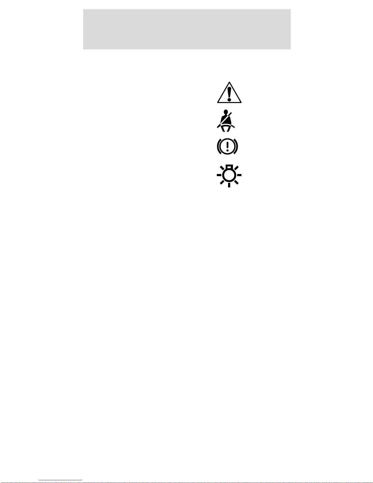
These are some of the symbols you may see on your
vehicle.
Safety Alert
Fasten Safety Belt
Brake System
Master Lighting Switch
INFORMATION ABOUT THIS GUIDE
The information found in this guide was in effect at
the time of printing. Ford Motor Company and/or
TH!NK Mobility, LLC may change the contents
without notice and without incurring obligation.
Introduction
3
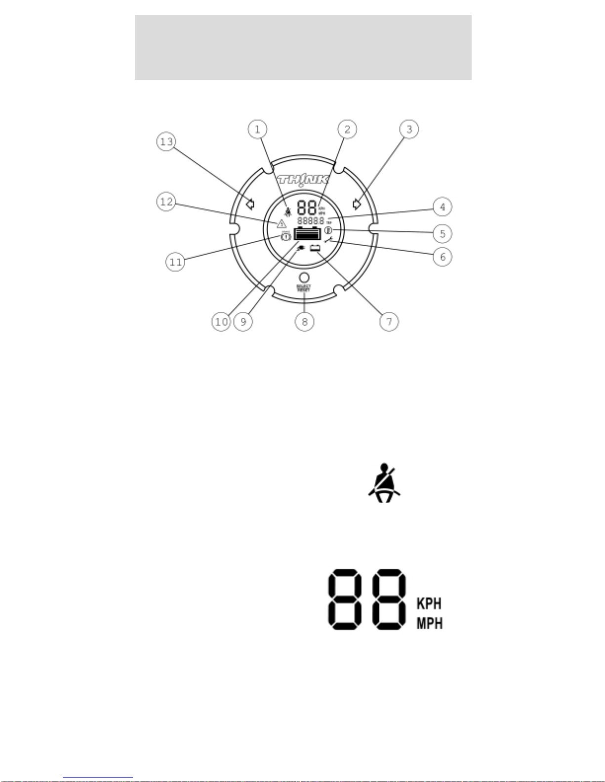
GAUGES
The instrument cluster LCD (liquid crystal display),
referred to as the “gauge,” will be activated if any of
the following conditions exist:
• Key switch is on
• Vehicle batteries are being recharged
1. Safety belt warning
indicator
The safety belt
warning icon will
illuminate for 30
seconds after the
vehicle is switched into D (Drive) mode.
2. Speedometer gauge
LCD
A two-digit LCD gauge
display shows the
vehicle speed in either
MPH or KPH,
depending on the selected mode. Vehicle speed is
shown while in R (Reverse), T (Turf), and D
(Drive) modes. The top speed of your vehicle in
Drive mode is 25 mph (40 km/h) and 15 mph
(24 km/h) in Turf mode.
Instrumentation
4
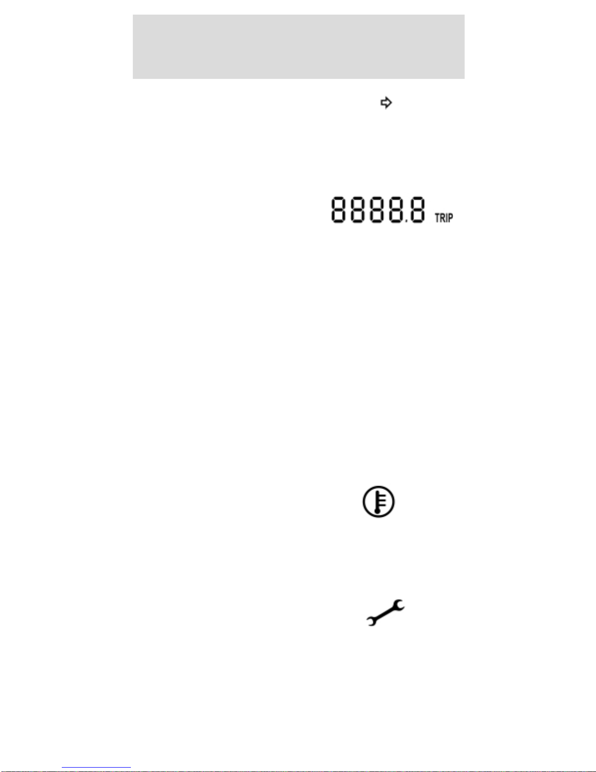
3. Right turn signal
indicator
The arrow will flash
when the turn signal
lever is pushed up. If the indicator flashes at a fast
rate, it has a malfunction, such as a burned out bulb.
4. Odometer/trip counter
display
A five-digit LCD
display shows the total accumulated miles traveled.
The display may be changed to measure a
particular trip distance. The drive mode selector
switch must be in the T (Turf) or D (Drive) mode
for this function. When the vehicle is restarted, the
display will return to the last mode manually set.
Changing and resetting the modes
The odometer/trip modes can be changed by
pressing the Select/Reset button on the instrument
cluster. The word “TRIP” will be displayed next to
the five-digit display when in Trip mode. To measure
a specific trip mileage, with the drive mode selector
switch in T (Turf) or D (Drive) reset the trip
odometer by pushing and holding the Select/Reset
button down for three seconds.
5. Drive system
over-temperature indicator
This icon will illuminate
if the drive system overheats. The vehicle will
drive normally 30 seconds, after which power will
be limited and will remain limited until the drive
system cools.
6. Service required indicator
The icon will illuminate
when the vehicle has a
malfunction in the motor
controller. Cycle the service disconnect switch off
and then back on. The service disconnect switch
is located below and behind the parking brake
lever within the seat stanchion (battery cover). It
Instrumentation
5

is a black rubber switch and faces the front of the
vehicle. To access the service disconnect switch,
remove the seat stanchion front cover, refer to
Flooded type batteries in Maintenance and
specifications. If the service required indicator is
still on, take your vehicle to an authorized Dealer
for the required maintenance to maintain your full
warranty coverage.
7. Battery water
reminder indicator
This icon indicates
that your vehicle’s
batteries require a
maintenance check of
the battery fluid levels. Distilled water or
demineralized water must be added as
needed. Your vehicle comes equipped with one of
two types of batteries: “flooded”, requiring water
level checks and maintenance refills; or the
optional sealed maintenance free, for which no
maintenance is required. This indicator will be
disabled if your vehicle is equipped with sealed
batteries. If you change the type of battery in your
vehicle, the TH!NK dealer will need to change the
battery setting in the gauge.
Resetting the battery water reminder indicator
Once the battery water has been checked, reset
the reminder by pressing and holding the
Select/Reset button for over three seconds while
in the R (Reverse) mode. The reminder will only
be reset during the following conditions: R
(Reverse) mode is selected with the drive mode
selector switch; instrument cluster gauge is in
flooded battery mode.
Instrumentation
6

8. System Select/Reset button
This button is used to
perform four functions.
a.
Each time the Select/Reset
button is pressed and
released in less than three
seconds, the odometer/trip counter will switch
between odometer and trip function displays. The
drive mode selector switch must be in the D (Drive)
or T (Turf) mode for this function.
b.
Pressing and holding the Select/Reset button, with
the odometer in the trip mode, for over 3 seconds
before releasing will reset the trip odometer to zero
and return to the trip odometer function. The drive
mode selector switch must be in the D (Drive) or T
(Turf) mode for this function.
c. Pressing and holding the Select/Reset button for
over three seconds will reset the battery water
reminder indicator. The drive mode selector
switch must be in the R (Reverse) mode and the
instrument cluster must be in “battery flooded
mode” for this function.
d. The Select/Reset button will allow you to
display diagnostic code(s). To display the
diagnostic code(s):
• With the key in the OFF position, press and hold
the Select/Reset button.
• Select D (Drive) mode with the key.
• Release the Select/Reset button.
• Press and release the Select/Reset button to scroll
through the diagnostic codes and their
corresponding odometer value.
•
All codes will be deleted by holding the Select/Reset
button for three seconds and releasing.
• Exit Service mode by selecting the OFF mode
with the key.
• Press and release the Select/Reset button.
Instrumentation
7

The following is a list of diagnostic codes.
Fault
Code
Description
05 Start switch fails to close.
06 Accelerator potentiometer pedal is depressed with
no direction selected.
08 Accelerator input voltage too low on power up
after initial drive mode selector switch closure.
09 Both forward and reverse direction switches are
closed at the same time.
11 Start switch closed on power up after initial drive
mode selector switch closure
15 Battery voltage is too low at initial drive mode
selector switch closure.
16 Battery voltage is too high at initial drive mode
selector switch closure.
23 Motor field current is high on start up in the
reverse direction.
24 Motor field current is high on start up in the
forward direction.
27 12V buss is too low.
41 Open thermal protector (TP) or transistor
over-temperature.
42 Motor armature offset voltage is too high.
43 Motor armature offset voltage is too low.
44 Armature transistor did not turn off properly.
45 Armature transistor did not turn on properly.
46 “Look Ahead” test for A2 volts less than 12% of
battery volts.
49 Motor field current is too low during the run mode.
51 Capacitor voltage is low before the line contactor
closes.
57 Controller “motor current sensor” input too low
while running.
75 Capacitor (1C) voltage too high during motoring
76 Capacitor (1C) voltage too high during
regenerative braking.
90 Motor thermostat is open during control operation.
Instrumentation
8
9. Battery charge
indicator
The icon will
illuminate when the
vehicle is connected
to an outside power
source to charge the batteries. The drive mode
selector switch should be in the OFF position
while the battery is charging.
Note: If this indicator is illuminated without the
vehicle being charged there is a charger problem.
The vehicle should be taken to an authorized
TH!NK dealer.
10. Battery level
indicator
The battery level
indicator shows the
power level remaining
in the batteries. Be
sure the vehicle is not charging when checking the
battery state of charge or the reading may be
incorrect. The battery level indicator shows full
whenever the vehicle is charging. Five bars are
illuminated when the batteries have a full charge.
At one bar, the battery outline will begin to flash.
The flashing frequency will increase as the state of
charge decreases. At low pack voltage, you may
see either five bars or zero bars with a flashing
outline. To maximize battery life, charge the
vehicle as soon as possible when the outline
begins to flash. When there are zero bars showing,
the batteries have been discharged to the point
where additional operation of your vehicle will
reduce battery life. Charge the vehicle batteries
immediately. If left uncharged, the batteries could
discharge to the point where the battery charger
will not turn on and battery damage may occur.
After a partial charge, the level may read higher
than it actually is. Driving a few miles will cause
the battery gauge to settle to an accurate level.
Instrumentation
9
11. Brake status
indicator
This icon will
illuminate if the
emergency brake
handle is not fully
released, or if the brake fluid level is low. It will
also flash while the park brake reminder is
sounding.
12. Electrical leakage
warning indicator
This icon will
illuminate to warn
that there is electrical
“leakage” or short
circuit to the vehicle frame. If the vehicle is wet
or has recently been washed, allow the vehicle to
fully dry and recheck for the indicator. If the
indicator is still present, take your vehicle to an
authorized TH!NK Dealer to correct the condition.
To avoid serious injury and/or death, never
perform any vehicle service or maintenance
while the electrical leakage warning indicator is
illuminated.
This vehicle contains a high voltage
electrical system. Serious injury, death,
and/or property damage may result if this vehicle
is not properly used, charged or serviced as stated
in this manual. Read this owner’s guide prior to
use, charging, or servicing this vehicle. Do not
drill, cut, or modify any part of this vehicle, as
high voltage wiring is present. Do not use jumper
cables. Only charge this vehicle with an approved
GFCI cord as stated in Battery charging.
Instrumentation
10

13. Left turn signal
indicator
The arrow will flash
when the turn signal lever is pushed down. If the
indicator flashes at a fast rate, it has a
malfunction, such as a burned out bulb.
Audible Indicators
Park brake reminder
The park brake reminder has a tone that sounds for
10 seconds when the drive mode selector switch is
turned to the OFF position with the parking brake
not set. It stops after 10 seconds or when the
parking brake is engaged. During this time the
vehicle is “active” with functional park brake
reminder and the gauge will be active and backlit.
After 10 seconds, the vehicle shuts down and park
brake reminder is no longer functional.
To avoid serious injury, death, and/or
property damage, always engage the parking
brake before leaving the vehicle.
Reverse alarm
When the vehicle is in R (Reverse), a tone is
generated to alert the driver and pedestrians.
Instrumentation
11
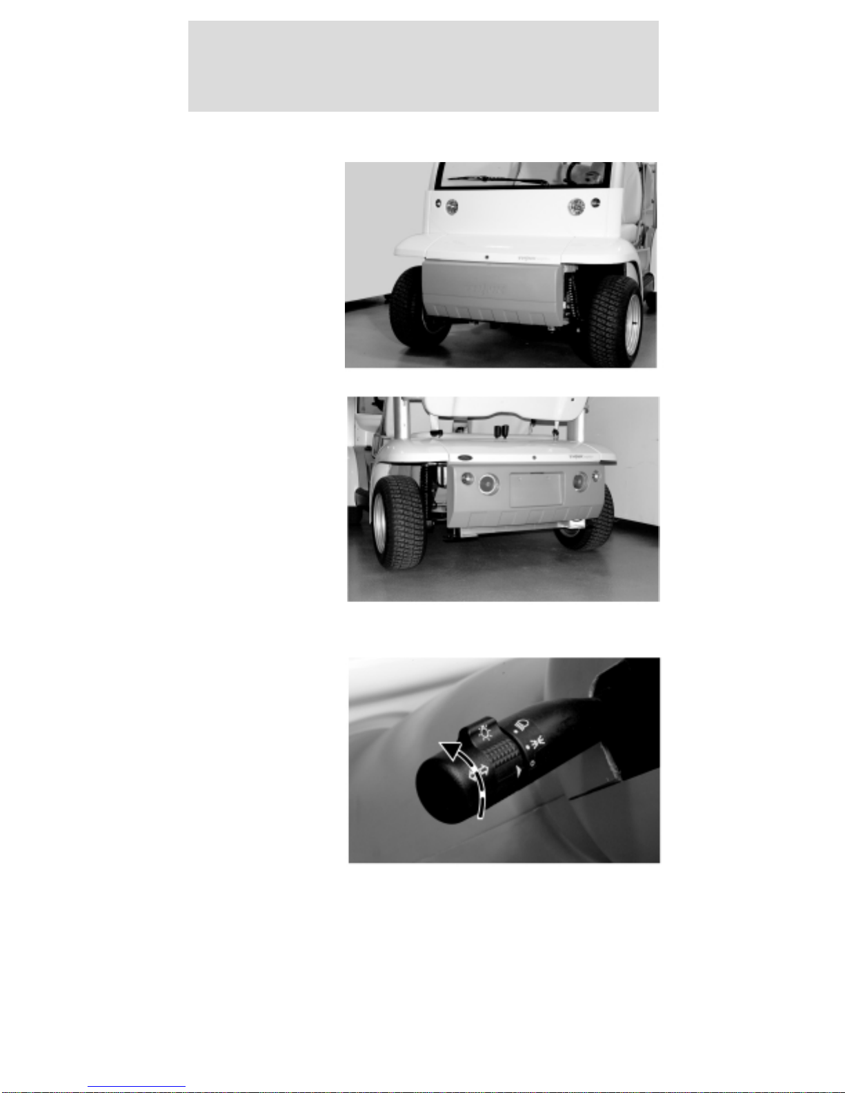
HEADLAMP CONTROL
The headlamps
are the larger
inboard lamps
on the front
panel of the
vehicle. The
smaller
outboard lamps
are the front
turn signals.
The headlamp
switch also
controls the tail
lights. The tail
lights are the
larger inboard
lamps
integrated into
the rear
bumper. The
smaller
outboard lamps are the rear turn signal lamps.
The headlamp
switch is
located on the
lever on the left
side of the
steering
column. The
center section
of the lever
rotates to turn
on the rear tail
lamps, license plate lamps, and the headlamps.
Lights
12
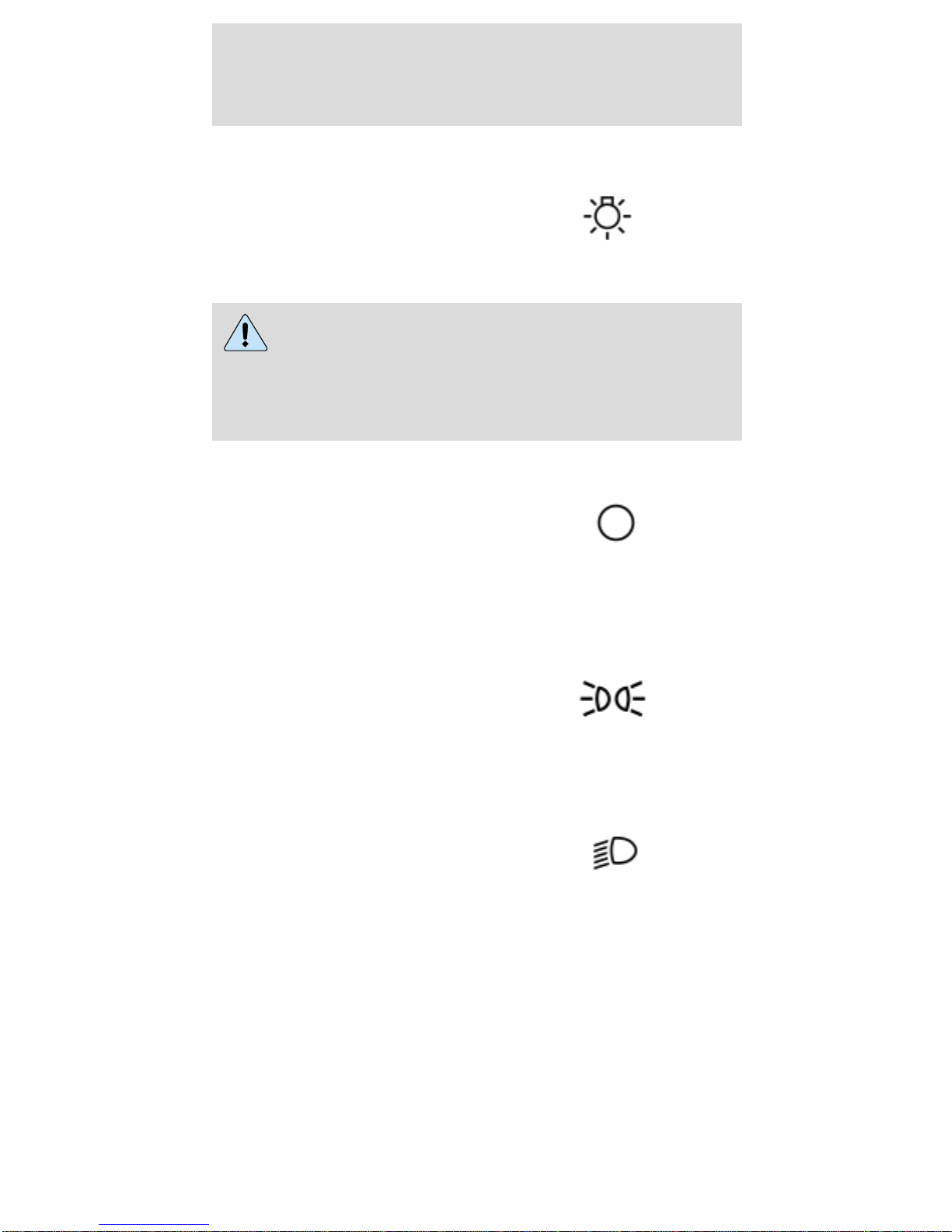
The headlamp switch
can be identified by the
bright bulb symbol.
Always remember to turn on your
headlamps at dusk and dawn and during
inclement weather. Failure to activate your
headlamps under these conditions could result in a
collision.
The OFF position is
indicated on the lever by
the O. When the switch
arrowhead is aligned
with the O symbol, the
exterior lamps are off.
The lights will not operate in the key OFF mode.
The first position above
the OFF position is the
rear tail lamps and
license plate lamp.
The second position
above the OFF position
will illuminate the
headlamps while the
rear tail lamps and
license plate lamps
remain on.
Pulling the headlamp switch rearward while it is in
the OFF position will cause the headlamps to turn
on as long as the switch is held rearward. There are
no high beams on this vehicle. Pulling the headlamp
switch rearward while it is in the ON position will
NOT change the performance of the headlamps.
Lights
13
TURN SIGNAL CONTROL
The headlamp
switch lever
also controls
the turn signals.
Push down to
activate the left
turn signal, and
push up to
activate the
right turn
signal. The
arrow indicator will flash on the instrument cluster
indicating that the turn signal is on.
AIMING THE HEADLAMPS
The headlamps on your vehicle are properly aimed
at the assembly plant.
If your vehicle has been in an accident the alignment
of your headlamps should be checked by a qualified
service technician.
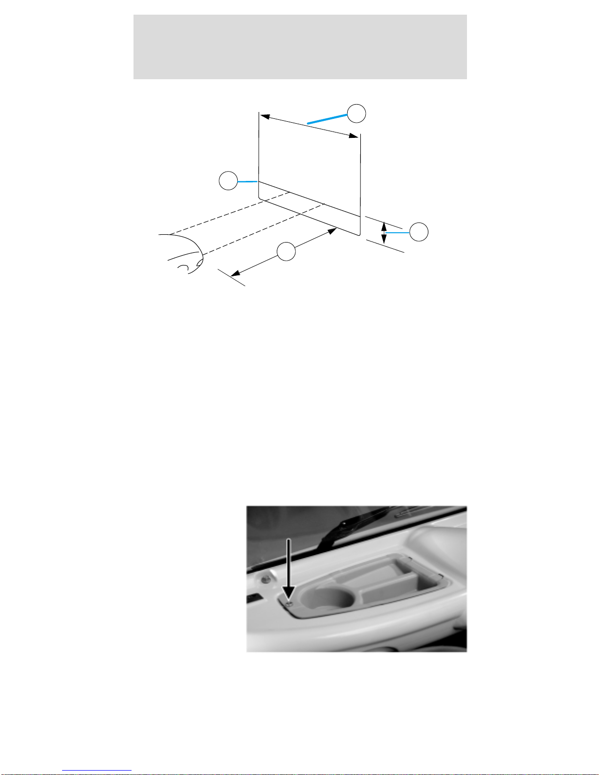
Vertical aim adjustment
1. Park the vehicle on a level surface approximately
7.6 meters (25 feet) from a vertical wall or screen
directly in front of it.
• (A) 2.43 meters (8 feet)
• (B) Height of top of lamp beam to ground
• (C) 6.09 meters (25 feet)
• (D) Horizontal reference line
Lights
14
2. Turn on the headlamps to illuminate the wall or
screen.
3. On the wall or screen you will observe an area of
high intensity light. The top of the high intensity
area should be .381 meters (2 ft 3 in) above the
ground. If not, the beam will need to be adjusted by
a qualified TH!NK technician.
BULB REPLACEMENT
Headlamps
To remove the headlamp bulb:
1. Remove the
scrivet and the
cowl tray panel.
A
D
B
C
Lights
15
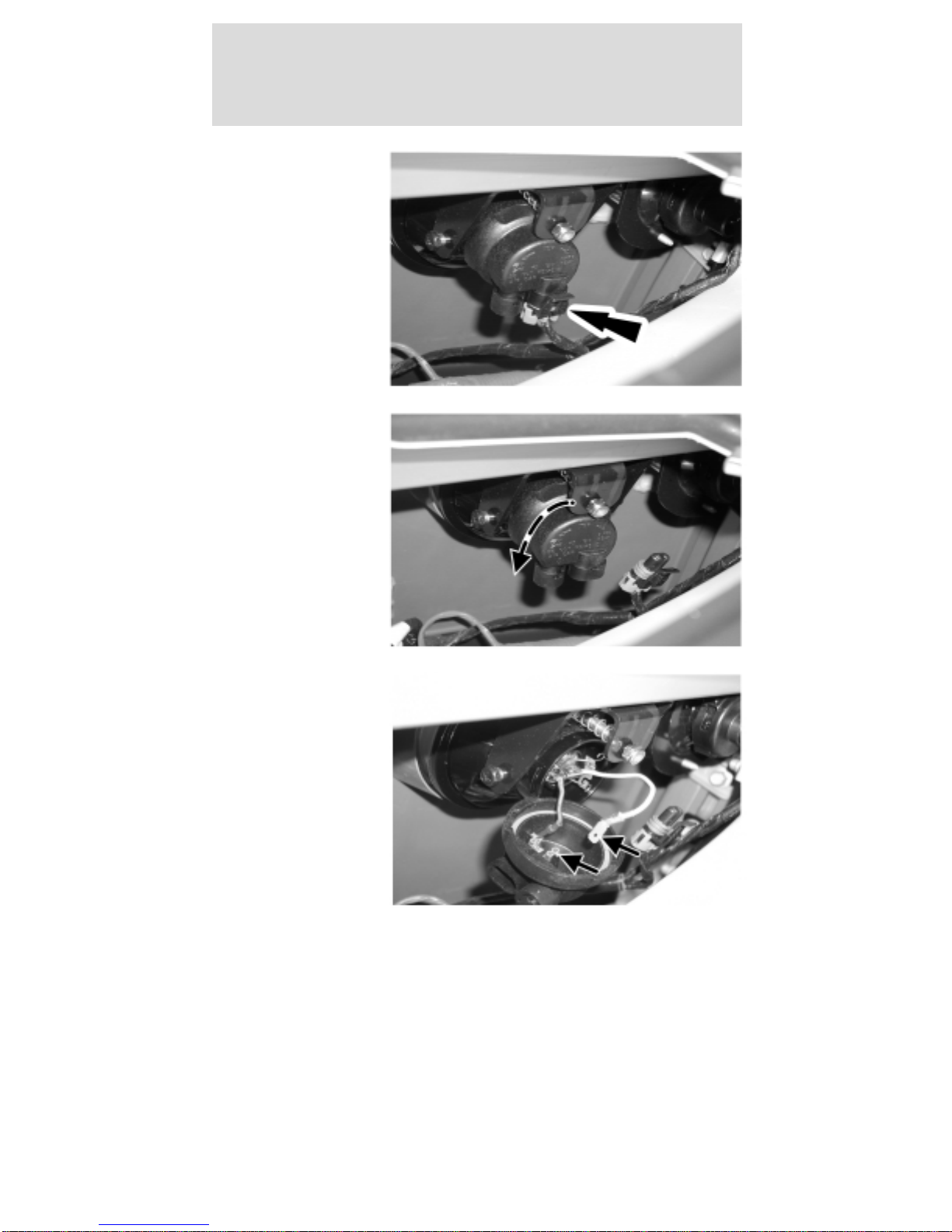
2. Disconnect
the headlamp
electrical
connector.
3. Rotate the
headlamp bulb
shield
counterclockwise
and flip down
to access the
bulb
connectors.
4. Pull the flat
connector
attached to the
white wire from
the headlamp
bulb shield.
Lights
16
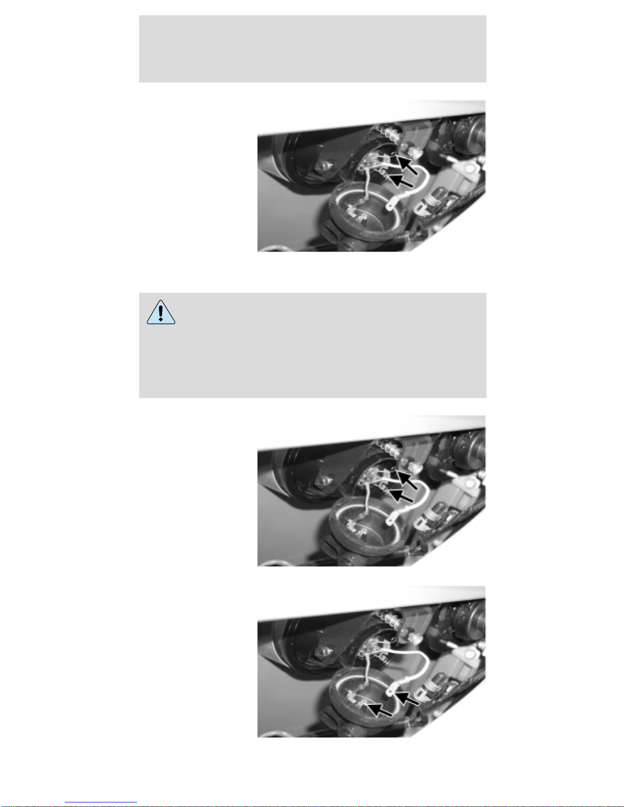
5. Push and
squeeze the two
bulb retainer
wires to
disengage them
from the
headlamp
housing.
Remove the
headlamp bulb.
To install the headlamp bulb:
Handle the halogen headlamp bulb carefully
and keep out of the children’s reach. Grasp
the bulb only by its metal base and do not touch
the glass. The oil from your hand could cause the
bulb to break the next time the headlamps are
operated.
1. Install the
headlamp bulb.
Squeeze and
push the two
bulb retainer
wires to engage
them to the
headlamp
housing.
2. Push the flat
connector
attached to the
white wire into
the headlamp
bulb shield.
Lights
17

3. Install and
rotate the
headlamp bulb
shield
clockwise.
4. Connect the
headlamp
electrical
connector.
5. Install the
cowl tray panel
and the scrivet.
Lights
18
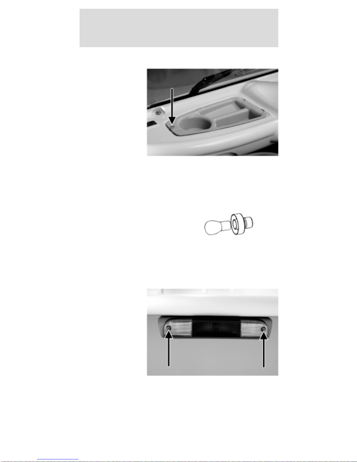
Replacing the front turn signals
1. Remove the
scrivet and cowl
tray panel.
(Driver side
shown; the
passenger side
is similar.)
2. Twist counterclockwise and remove the front turn
signal bulb retainer.
3. Remove the bulb.
4. Install the new bulb.
5. Install the removed
components.
Replacing the rear high-mount stop and reverse
lamp bulbs
1. Remove the
two screws and
pull out the
lamp assembly
to expose the
bulb sockets on
the back.
Lights
19
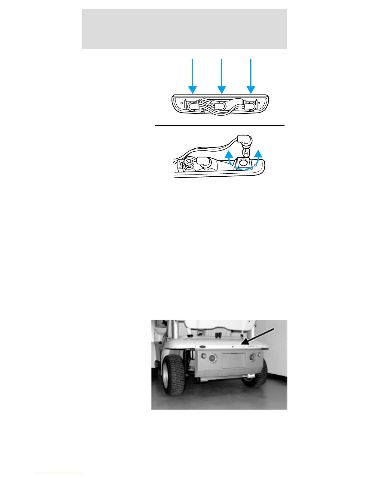
2. Rotate the
bulb socket
counterclockwise
and pull out to
access the bulb.
3. To remove the bulb, pull it straight out of the
socket.
4. Insert a new bulb into the socket until it is fully
seated.
5. Install the socket into the back of the lamp
assembly and turn clockwise until it is locked into
place.
6. Position the lamp assembly into the vehicle
housing and install the two screws. Tighten the
screws firmly, but do not over-tighten.
Over-tightening can cause damage to the lamp.
Replacing the rear turn signals
1. Unlock and
remove the
decklid (if
equipped).
2. From inside
the rear wheel
housings,
remove the six
rear bumper
bolts and
carefully lower
the bumper.
Lights
20
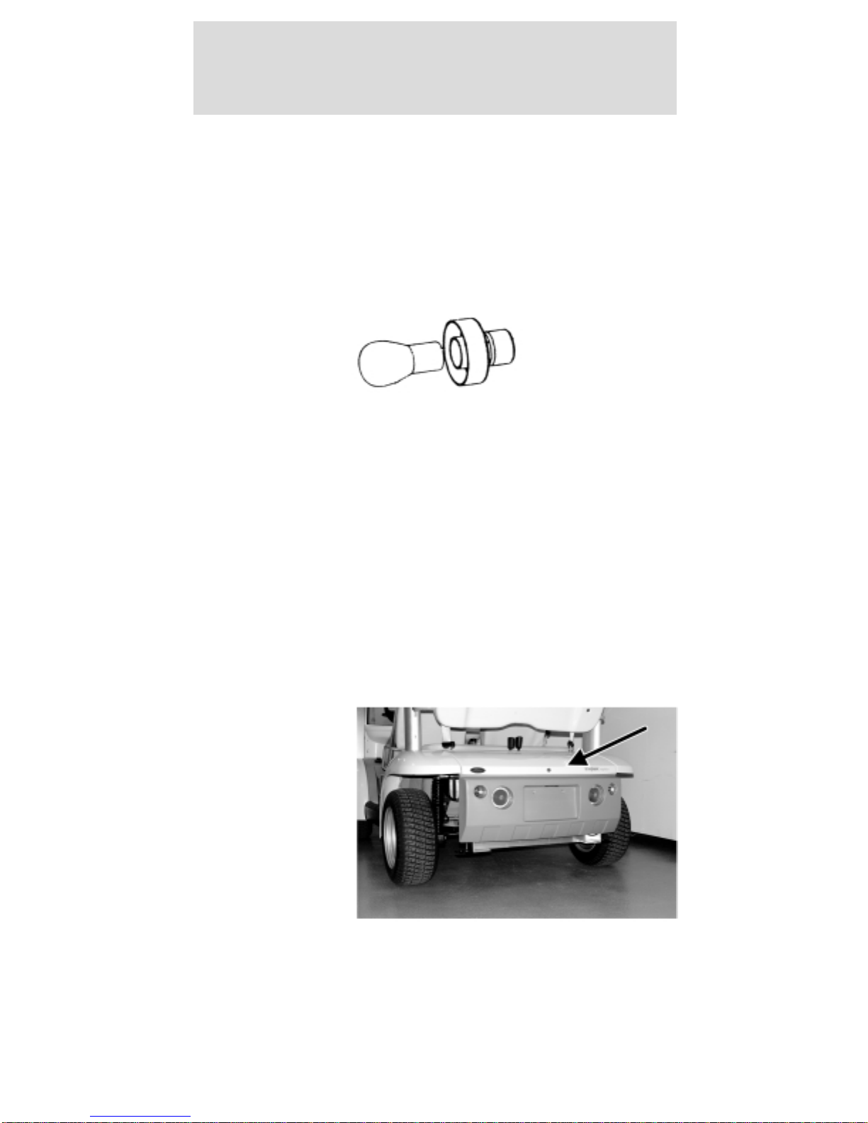
3. Twist counterclockwise and remove the rear turn
signal bulb retainer.
4. Remove the bulb.
5. Install the new bulb.
6. Install the removed parts. Tighten the rear
bumper bolts to 8–10 N•m.
7. Install and lock the decklid.
Replacing the tail lights/brake lights
Note: The bulb in the tail light/brake light assembly
is not serviceable. The entire assembly must be
replaced.
1. Unlock and
remove the
decklid.
2. Disconnect the electrical connector.
Lights
21
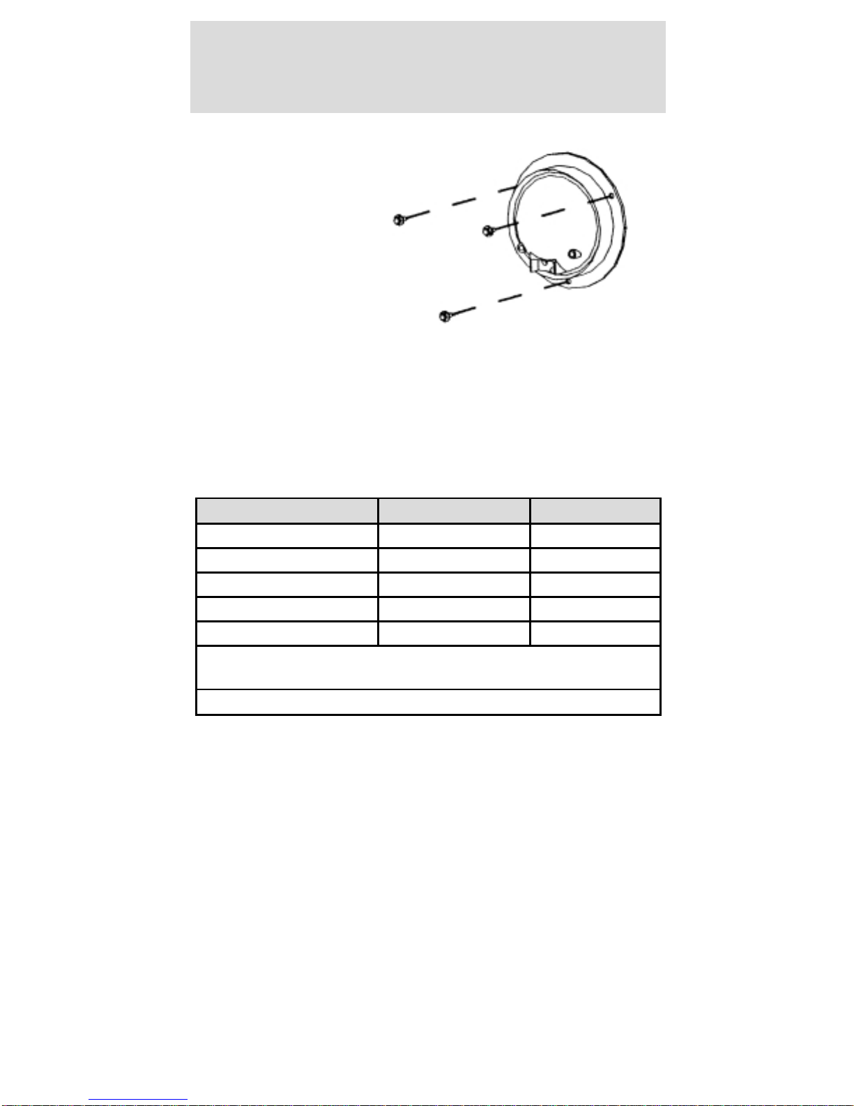
3. Remove the
three screws
and the rear
turn signal
assembly.
4. Connect the
electrical
connector and
install the new
lamp assembly.
5. Tighten the screws firmly, but do not over-tighten.
6. Install and lock the decklid.
Using the right bulbs
Replacement bulbs are specified in the chart below.
Function Number of bulbs Trade number
Headlamp 2 H3
Backup lamp 2 906
License plate lamp 1 W5W
High-mount stop lamp 1 922
Turn signal lamp 4 7507/PY21W
All replacement bulbs are clear in color except where
noted.
To replace all instrument panel lights - see your Dealer.
Lights
22
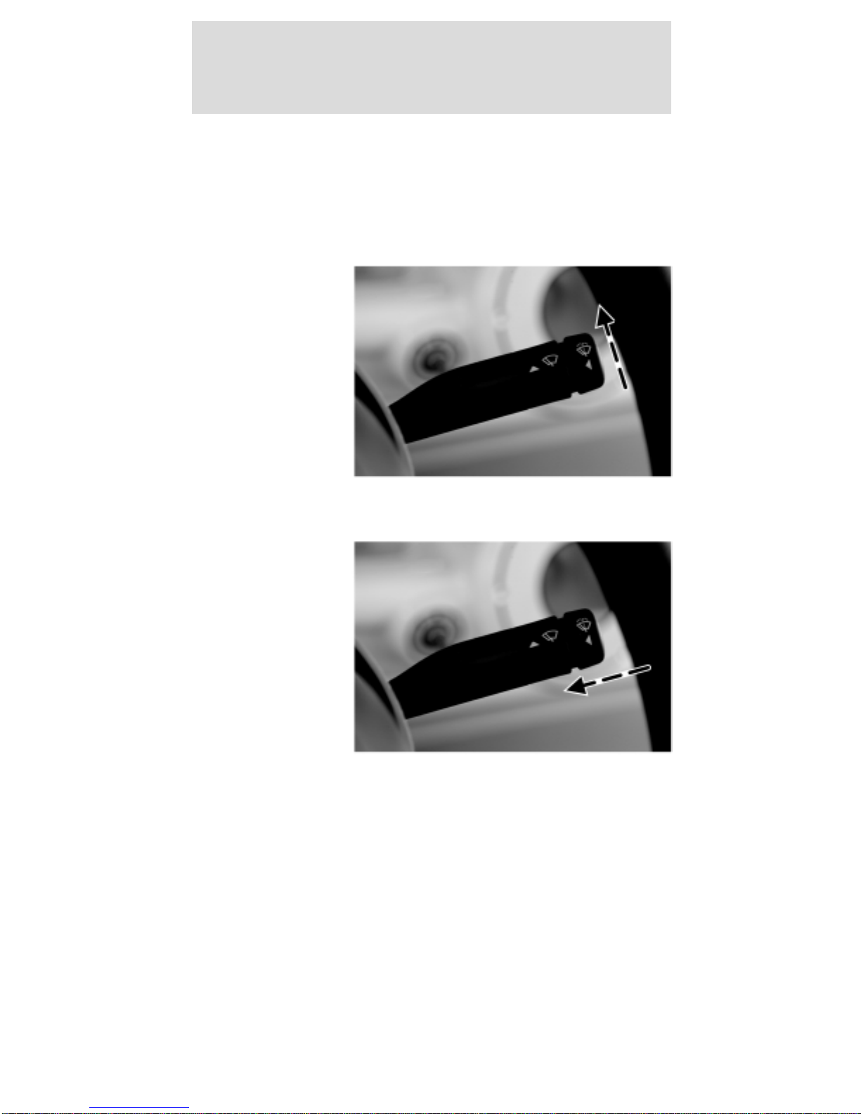
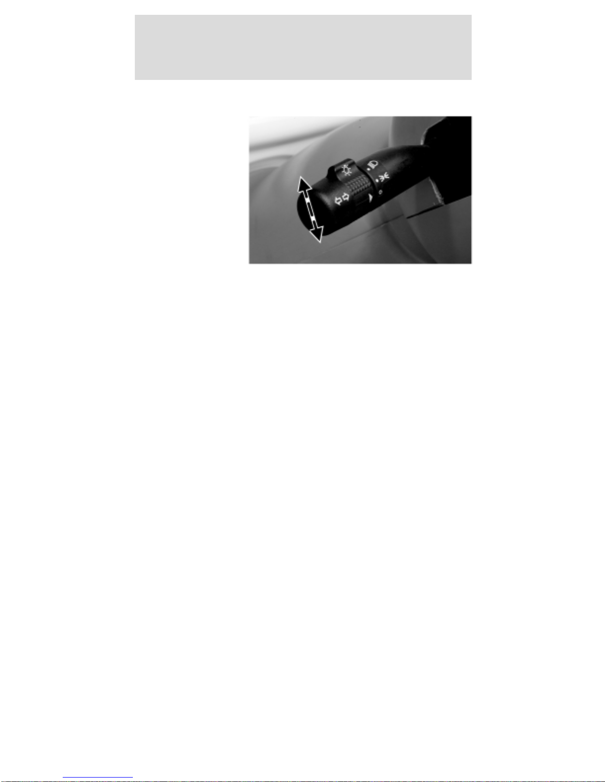
WINDSHIELD WIPER/WASHER
Front wiper control
The front windshield wiper is controlled by the lever
mounted on the right side of the steering column.
To operate the
windshield
wiper, with the
drive mode
selector switch
in R (Reverse),
T (Turf) or D
(Drive), push
the lever up.
Washer
To operate the
windshield
washer, turn
the wiper on,
push the end of
the lever in
toward the
steering column
and hold it in
for the desired
length of spray.
Release the lever to stop the washer and turn the
wiper off.
Driver controls
23

Checking windshield washer fluid
To check the windshield washer fluid level:
1. Unlock and
remove the
hood.
2. Observe the
level of fluid in
the reservoir on
the right side of
the
compartment.
3. If necessary, unscrew the reservoir cap and fill
with pre-mixed washer fluid.
4. Install the reservoir cap.
5. Install and lock the hood.
Checking the wiper blade
If the wiper operation results in streaky or
obstructed vision, clean the blade with mild soap
and water to remove any foreign material, grease or
dirt. If the wiper operation still results in poor
visibility, inspect the blade, the insert, and the arm.
• Confirm that the arm and blade are not bent or
damaged. If any defect is found, the part must be
replaced to assure proper operation.
• Confirm that the wiper blade insert is supple and
pliable. If it has become hard, cracked, or split it
must be replaced for proper operation.
Driver controls
24
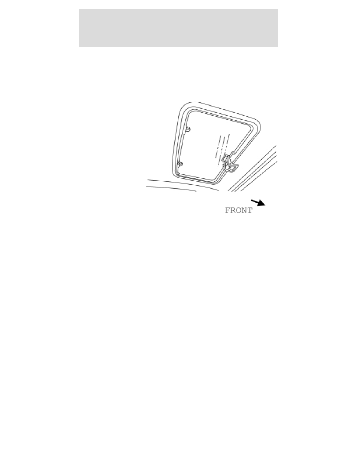
SUN ROOF/ROOF VENT (IF EQUIPPED)
The sun
roof/roof vent is
located in the
roof panel.
Opening it
increases air
flow to the
driver and front
passenger.
To open the sun roof/roof vent:
1. Pull down on the sun roof/roof vent handle to
unlock the sun roof/roof vent.
2. Rotate the handle rearward and swivel up until it
locks in one of the five raised positions.
To close the sun roof/roof vent:
1. Pull down on the sun roof/roof vent handle to
unlock the sun roof/roof vent.
2. Rotate the handle forward and swivel up until it
locks in the closed position.
Driver controls
25
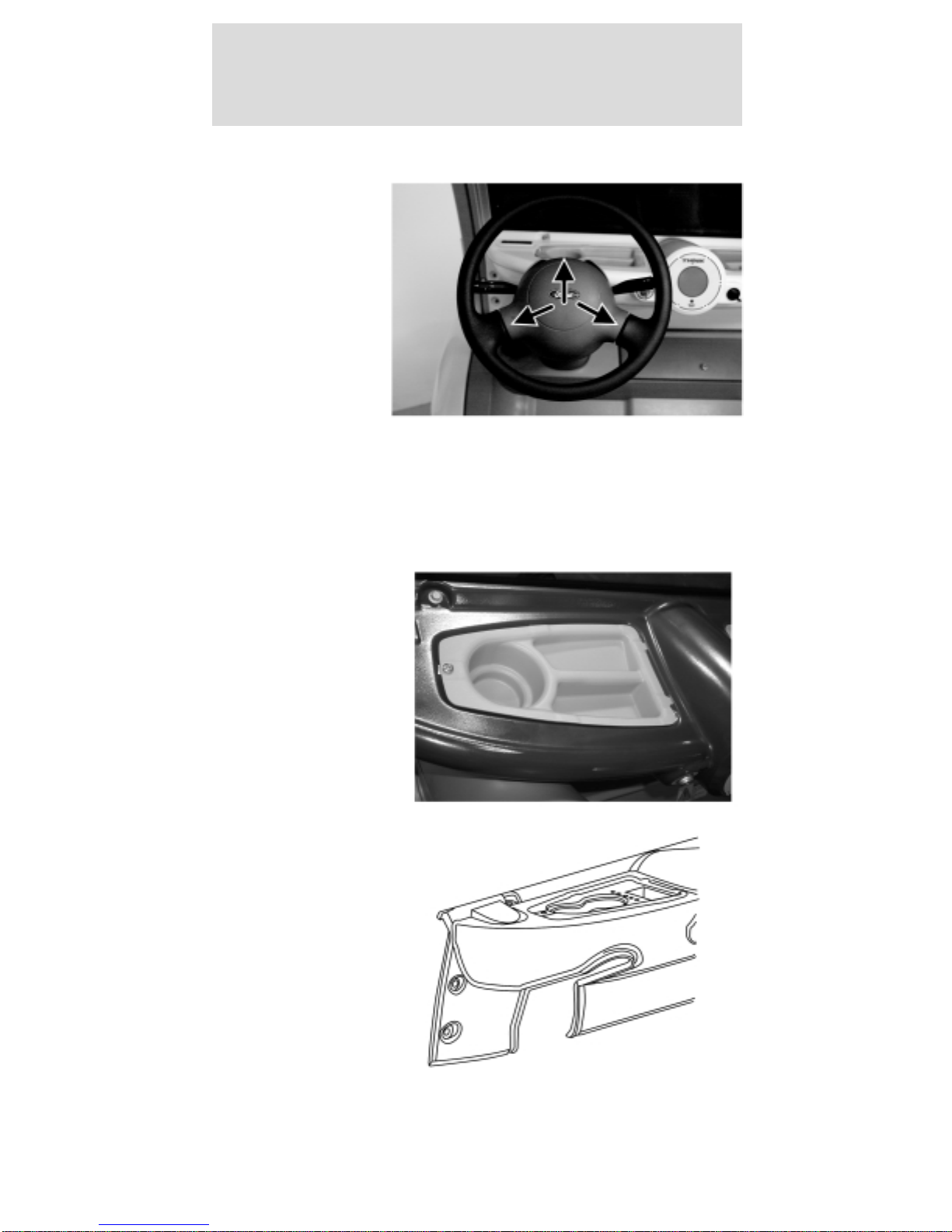
HORN
To activate the
horn, push one
of the three
horn contact
points on the
steering wheel.
CUPHOLDER
Your vehicle is equipped with a number of
convenient cupholders, depending on which storage
trays your vehicle has.
Driver side
instrument
panel storage
tray with
cupholder and
storage
compartments
(Passenger side
is similar.)
Optional cowl
tray with sport
package.
Driver controls
26
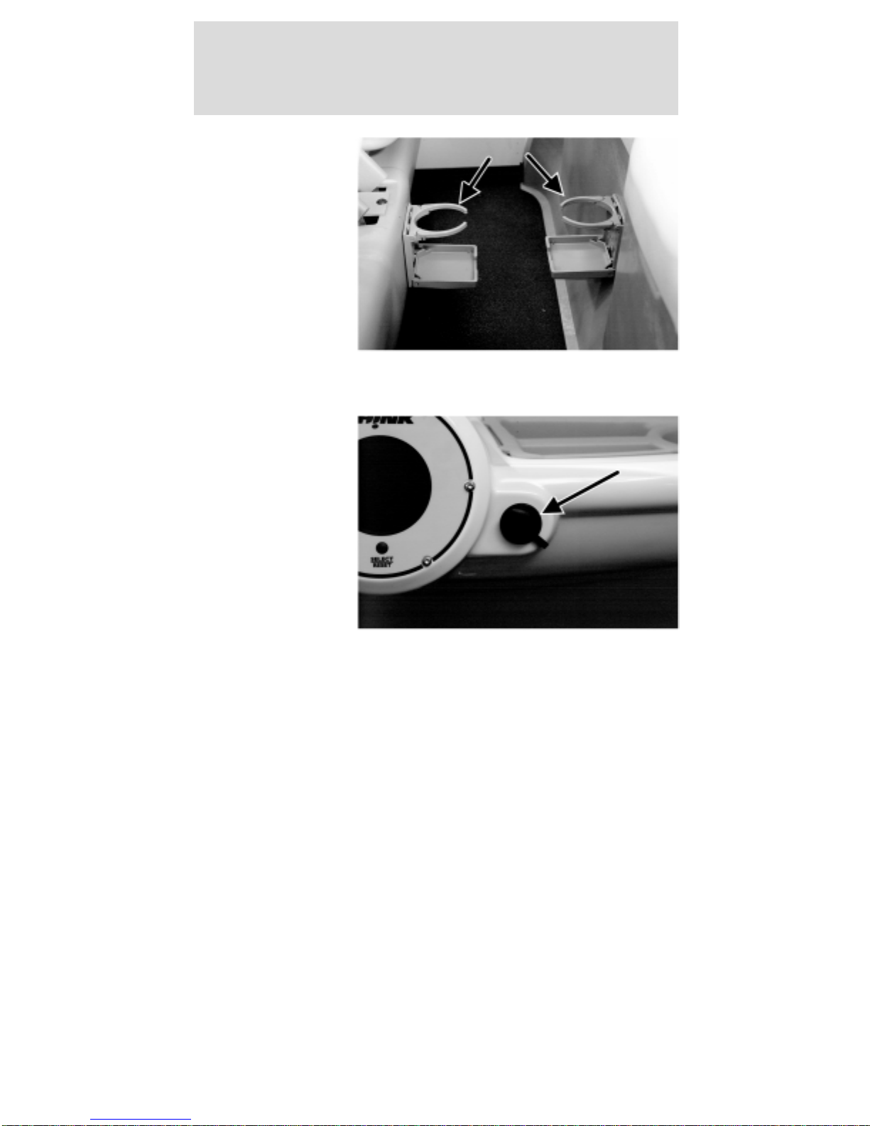
Rear cupholders
(4-passenger
only)
15 A POWER POINT (IF EQUIPPED)
The 15A power
point is located
on the
passenger side
of the
instrument
panel. The
power point is
operational at
all times. For
safety, there is
a rubber plug protecting the power point. To use the
power point, remove the rubber plug and insert the
desired accessory plug. Always keep the rubber plug
inserted into the power point when not in use.
Note: The power point should not be used during
battery charging.
MIRRORS
Interior rear view mirror
The interior rear view mirror is adjustable for both
day and night use. To reduce the glare at night, use
the manual switch at the base of the mirror to put
the mirror in night mode.
Driver controls
27
Exterior mirror
The exterior rear view mirrors (right-hand mirror is
optional) are adjusted manually. Your view should be
adjusted so that the vehicle’s rear tires are just
visible in the bottom inside corner of the mirror.
This will minimize any “blind spot” in your field of
view.
Always confirm it is clear behind you before
changing lanes or backing up to avoid a
collision.
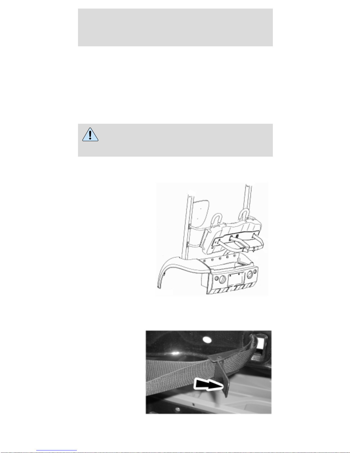
GOLF RACK (IF EQUIPPED)
To mount golf
bags in the golf
rack:
1. Unlock the decklid. To remove the decklid, lift
and raise the decklid.
2. Pull rearward
on the bag belt
webbing
release/locking
lever.
Driver controls
28

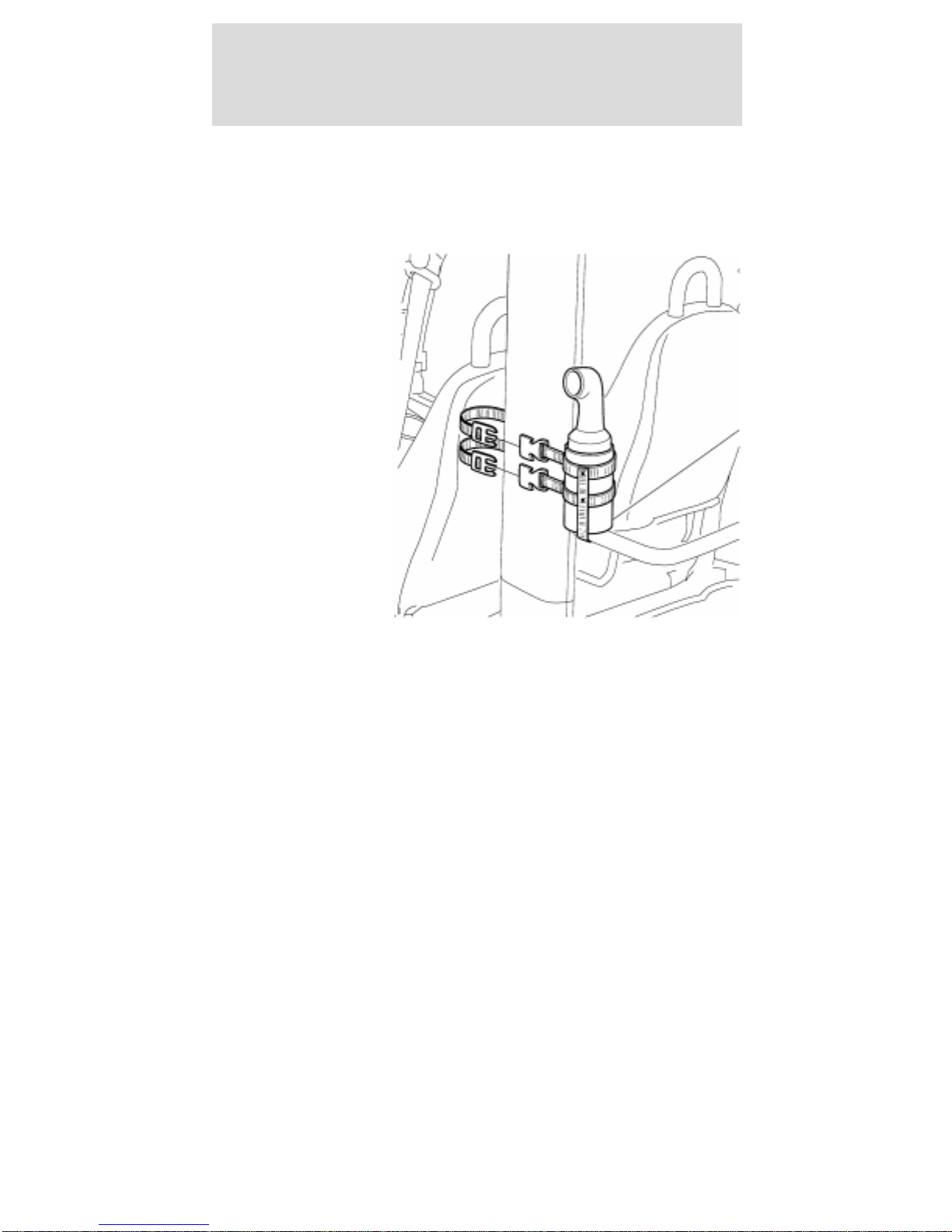
3. Pull the webbing out of the release/locking lever.
Note: The base of the golf bag should rest on the
top of the golf bag tray.
4. Position the golf bag in the trunk area.
5. Route the webbing through the golf bag handle
and through the release/locking lever.
6. Remove any slack from the webbing and lock the
release/locking lever.
FLOOR MATS
The floor mats are fastened to the floor with scrivets
that can be loosened and removed for cleaning
under the floor mats.
SCORECARD HOLDER (IF EQUIPPED)
The scorecard holder is attached to the glove box
door with magnets after attaching a magnetic disc to
the glove box door.
STEREO (IF EQUIPPED)
For operating instructions for the stereo, please
refer to the instructions provided with the unit.
Driver controls
29
SAND AND SEED BOTTLE AND HOLDER
(IF EQUIPPED)
The sand and
seed bottle
holder is
mounted to the
left-hand side
roof pillar.
Driver controls
30
 Loading...