

Page 1
SECTION 303-04B : Fuel Charging and Controls — 4.6L (2V) a nd 5.4L (2V) 2001 F-150 Worksho p Manual
Page
1
of
7
2001 F
-
150 Workshop Manual
10/24/2009
http://www.fordtechservice.dealerconnection.com/pubs/content/
...
REMOVAL AND INSTAL LATION
Procedure revision date: 06/19/2000
Fuel Injection Supply Manifold—Fuel Injection
Material
XO-10W20-QSP or DSP clean engine oil or equivalent
—
Removal
WARNING: Do not smoke o r carry lighted tobacco or open flame of any type when wo rking on or near any fuel-related components. Highly flamm able mixtures are
always present and may be ignited. Failure to follow thes e instructions may result in personal injury.
WARNING: Fuel in the fuel system remains under high pressure even when the engine is not running. Before working on or disconnecting any of the fuel lines or fuel
system components, the fu el system pressure must be relieved. Failure to follow the se instructions may result in personal injury.
All engines
1. Disconnect the battery ground cable (14301). For additiona l information, refer toSection 414-01.
2. Relieve the fuel pressure. For additional information, refer toSection 310-00A.
3. Partially drain the cooling system. For additional information, refer toSection 303-03A or Section 303-03B.
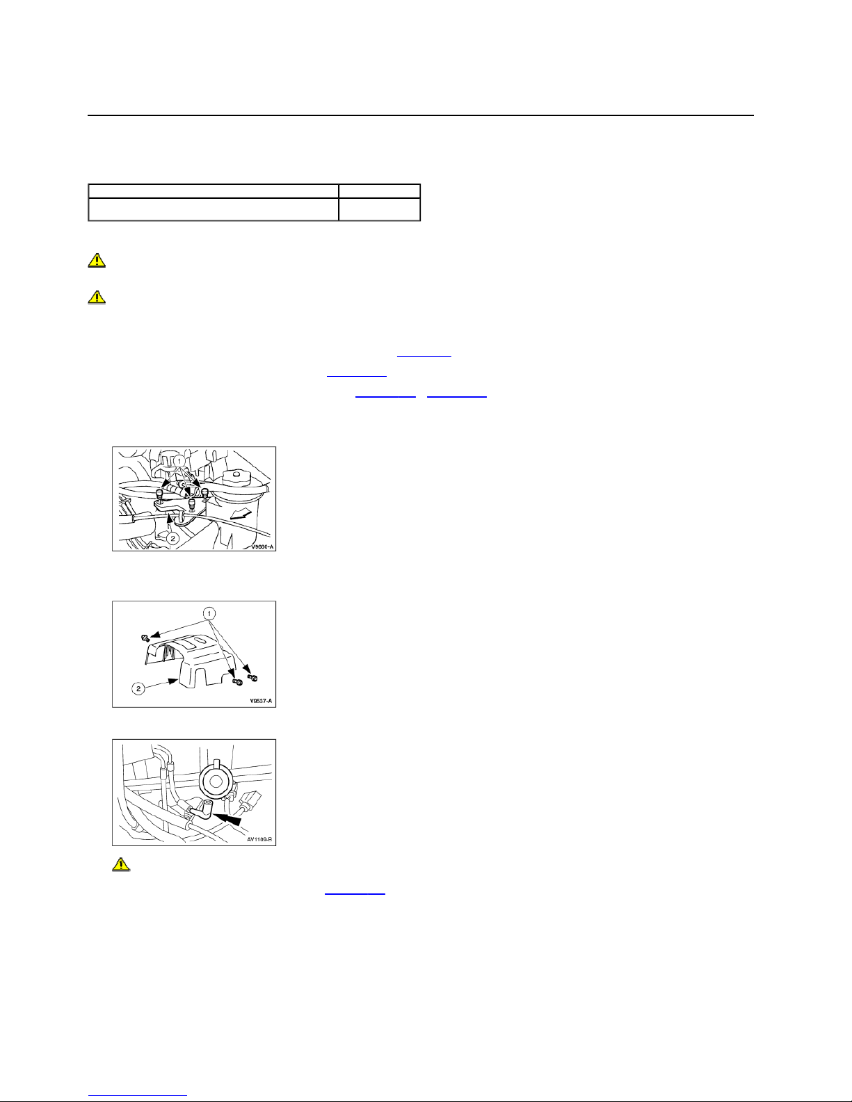
4. Remove the power steering reservoir bracket.
1. Remove the bolts.
2. Position the power steering reservoir bracket out of the way.
Item Specification
WSS-M2C153-H
5. Remove the accelerator control splash shield.
1. Remove the bolts.
2. Remove the accelerator control splash shield.
6. Disconnect the fuel pressure regulator valve vacuum hose.
7. CAUTION: After disconnecti ng, plug the fuel lines to prevent leakage.
Disconnect the fuel lines. For additional information, refer toSection 310-00A.
8. Disconnect the eight ignition coil electrical connectors.
Page 2
Page
2
of
7
2001 F
-
150 Workshop Manual
10/24/2009
http://www.fordtechservice.dealerconnection.com/pubs/content/
...
9. Disconnect the eight fuel injector electrical connectors.
4.6L engines
10. Remove the nut and disconnect the brake booster vacuum hose and bracket
5.4L engines
11. Remove the brake booster bracke t and tube.
1. Remove the nut.
2. Release and move the two h ose clamps.
3. Remove the brake booster t ube.
All engines
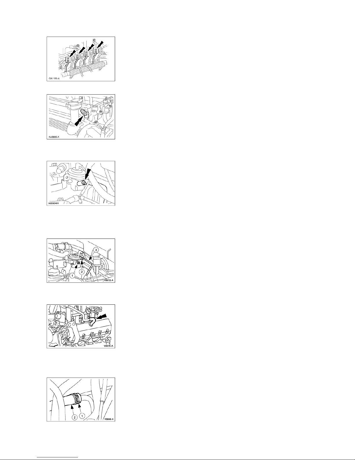
12. Remove the positive crankcase ventilation (PCV) hose.
5.4L engines
13. Disconnect the water heater inlet tube hose.
1. Release and move the hose c lamp.
2. Disconnect the water heater inlet tube hose and position asi de.
Page 3

4.6L engines
Page
3
of
7
2001 F
-
150 Workshop Manual
10/24/2009
http://www.fordtechservice.dealerconnection.com/pubs/content/
...
14. Disconnect the EGR connections:
EGR valve to exhaust manifold tube upper fitting
Differential pressure feedback EGR transducer electrical connector
EGR valve to exhaust manifold tube lower fitting
5.4L engines
15. Disconnect the exhaust gas recircu lation (EGR) valve to exhaust manifold tube.
1. Disconnect the two different ial pressure feedback EGR transducer hoses.
2. Remove the EGR valve to exhaust manifold tube upper fitting.
3. Remove the EGR valve to exhaust manifold tube lower fitting.
All engines
16. Remove the EGR tube.
17. Disconnect the EGR valve vacu um hose.
18. Disconnect the vapor managemen t valve (VMV) hose.
Page 4

Page
4
of
7
2001 F
-
150 Workshop Manual
10/24/2009
http://www.fordtechservice.dealerconnection.com/pubs/content/
...
19. Remove the bolts and lift the fuel injection supply manifold (9F792) and injectors upward, out of the intake manifold (9424).
20. Remove the fuel injectors from the fuel injection supply manifo ld.
21. Inspect the two O-ring seals from each fuel injector. Install new O-ring seals as needed.
Installation
All engines
1. NOTE: Lubricate the new O- ring seals with clean engine oil to aid installation.
Install two O-ring seals to each fuel injector.
2. Install the fuel injectors into the fuel injection supply manifold.
3. Install the four bolts.
4. Connect the VMV hose.
5. Connect the EGR valve hos e.
Page 5

Page
5
of
7
2001 F
-
150 Workshop Manual
10/24/2009
http://www.fordtechservice.dealerconnection.com/pubs/content/
...
6. Position EGR tube on the en gine.
4.6L engines
7. Install the exhaust manifold-to-EGR valve tube.
8. Connect the differential pres sure feedback EGR transducer electrical connector.
5.4L engines
9. Install the exhaust manifold-to-EGR valve tube and connect the differential pressure feedba ck EGR transducer hoses.
All engines
10. Install the PCV hose.
Page 6

Page
6
of
7
2001 F
-
150 Workshop Manual
10/24/2009
http://www.fordtechservice.dealerconnection.com/pubs/content/
...
4.6L engines
11. Connect the brake booster vacuum hose and bracket and install the nut.
5.4L engines
12. Install the brake booster bracket and tube.
1. Install the brake booster tub e.
2. Install the two hose clamps.
3. Install the nut.
13. Connect the water heater inlet tube hose.
1. Connect the water heater inl et tube hose.
2. Compress and install the hose clamp.
All engines
14. Connect the eight fuel injector electrical connectors.
15. Connect the eight ignition coil electrical connectors.
16. Connect the fuel lines. For additio nal information, refer toSection 310-00A.
Page 7

17. Connect the fuel pressure regulator valve vacuum hose.
Page
7
of
7
2001 F
-
150 Workshop Manual
10/24/2009
http://www.fordtechservice.dealerconnection.com/pubs/content/
...
18. Install the accelerator control splash shield.
19. Install the power steering reservo ir bracket.
20. Connect the battery ground cable. For additional information, refer to Section 414-01.
21. Fill the cooling system. For addi tional information, refer toSectio n 303-03A or Section 303-03 B.
 Loading...