

Page 1
SECTION 308-07A: Tr ansfer Case — Genera l Information 2000 Ranger Worksho p Manual
Page
1
of 622000 Ranger Workshop Manual
1/18/2012
http://www.fordtechservice.dealerconnection.com/pubs/content/~WSYL/~MUS~LEN/21/
...
DIAGNOSIS AND TES TING
Transfer Case
Refer to Wiring Diagrams Ce ll 34, Electronic Shift Control for schematic and connector inform ation.
Refer to Wiring Diagrams Ce ll 59, Generic Electronic Module for schematic and connector information.
Special Tool(s)
73III Automotive Meter
105-R0057 or equivalent
Worldwide Diagnostic System (W DS)
418-F224,
New Generation STAR (NGS) Tester
418-F052, or equivalent scan tool
R-134A Manifold Gauge Set or equivalent
176-R032A
Seal Depth Set/Vacuum Test Cap or equivalent
205-400
Seal Replacer/CV Tester or equivalent
205-399
Procedure revision date: 06/18/1999
Vacuum Pump or equivalent
014-R1054
Vacuum Test Cap or equivalent
205-401
Pulse Vacuum Hublock Vacuum Schematic
Page 2

Wiring harness
Page
2
of 622000 Ranger Workshop Manual
1/18/2012
http://www.fordtechservice.dealerconnection.com/pubs/content/~WSYL/~MUS~LEN/21/
...
Inspection and Verification
1. NOTE: The GEM/CTM must be reconfigured upon replacement. Refer to the scan tool help s creen on the configuration card to program the tire size and axle ratio.
The transfer case is a generic electronic module (GEM) controlled system.
2. Verify the customer concern by operating the 4X4 system.
3. Visually inspect for obvious signs of mechanical and electrical damage.
Visual Inspection Chart
Mechanical Electrical
Switch(es)
4. If the concern remains after the inspection connect the scan too l to the data link connector (DLC) located beneath the instrument panel and select the vehicle to be tested from the
scan tool menu. If the scan tool does not communicate with the vehicle:
5. If the scan tool still does not communicate with the vehicle, re fer to the scan tool manual.
6. Perform the DATA LINK DIAGN OSTIC TEST. If the scan tool responds with:
7. If the DTCs retrieved are related to the concern, go to GEM/CTM Diagnostic Trouble Code (DT C) Index to continue diagnostics.
8. If no DTCs related to the concern are retrieved, proceed to Sym ptom Chart to continue diagno stics.
GEM/CTM Diagnostic Trouble Code (DTC) Index
GEM/CTM Diagnostic Troubl e Code (DTC) Index
DTC Description
B1302 Accessory Delay Relay Coil C ircuit
Failure
Fuse(s)
Connections
Lamps
Circuitry
check that the program card is properly installed.
check the connections to the vehicle.
check the ignition switch position.
CKT914, CKT915 or CKT70 =ALL ECUS NO RESP/NOT EQUI P, refer to Section 418-00.
NO RESP/NOT EQUIP for GEM/CTM, go to Pinpoint Test D.
SYSTEM PASSED, retrieve and record the continuous diagno stic trouble codes (DTCs), era se the continuous DTCs and perf orm self-test diagnostics for the GEM/CTM.
DTC
Caused By Action
GEM REFER to Section 501-11.
Page 3
B1304 Accessory Delay Relay Coil C ircuit
Page
3
of 622000 Ranger Workshop Manual
1/18/2012
http://www.fordtechservice.dealerconnection.com/pubs/content/~WSYL/~MUS~LEN/21/
...
Short to Battery
B1313 Battery Saver Relay Coil — Circuit
Failure
B1315 Battery Saver Relay Coil Circ uit
Short to Battery
B1317 Battery Voltage HIGH GEM/CTM REFER to Section 414-00.
B1318 Battery Voltage Low GEM/CTM REFER to Section 414-00.
B1322 Driver Door Ajar Circuit Short to
Ground
B1323 Door Ajar Lamp Circuit Failure GEM/CTM REFER to Section 413-01.
B1325 Door Ajar Lamp Circuit Short to
Battery
B1330 Passenger Door Ajar Short to
Ground
B1340 Chime Input Request Short to
Ground
B1342 GEM/CTM is Defective GEM/CTM CLEAR the DTCs. RETRIEVE the DTCs. If DTC B1342 is retrie ved, REPLACE the GEM/CTM ; REFER to Section 419-10.
B1352 Ignition Key-In Circuit Fai lure GEM/CTM REFER to Section 413-09.
B1355 Ignition RUN Circuit Failure GEM/CTM REFER to Section 211-05.
B1359 Ignition RUN/ACC Circuit Failu re GEM/CTM REFER to Section 211-05.
B1371 Illuminated Entry Relay Circui t
Failure
B1373 Illuminated Entry Relay Short to
Battery
B1398 Power Window driver One-Touch
Window Relay Circuit Failure
B1400 Power Window driver One-Touch
Window Relay Coil Circuit Short to
Battery
B1404 Driver Power Window Down Sw itch
Input Open CKT
B1405 Driver Power Window Down Sw itch
Input Short Circuit to Battery
B1410 Driver Power Window Motor C ircuit
Failure
B1426 Seat Belt Lamp Circuit Short to
Battery
B1428 Seat Belt Lamp Circuit Failure GEM/CTM REFER to Section 413-01.
B1431 Wiper Brake/Run Relay — Ci rcuit
Failure
B1432 Wiper Brake/Run Relay — Sho rt to
Battery
B1434 Wiper Hi/Lo Speed Relay — Circuit
Failure
B1436 Wiper Hi/Lo Speed Relay Circ uit
Short to Battery
B1438 Wiper Mode Select Switch Circu it
Failure
B1441 Wiper Mode Select Switch Short to
Ground
B1446 Wiper Park Sense Circuit Failu re GEM/CTM REFER to Section 501-16.
B1450 Wiper/Wash Interval Delay Swit ch
Input Circuit Failure
B1453 Wiper/Wash Interval Delay Swit ch
Input Short to Ground
B1458 Wiper/Washer Pump Motor Re lay
Circuit Failure
B1460 Wiper/Washer Pump Motor Re lay
Coil Short to Battery
B1462 Seat Belt Switch Circuit Failure GEM/CTM REFER to Section 413-09.
B1466 Wiper Hi/Low Speed Not Switching GEM/CTM REFER to Section 501-16.
B1467 Wiper Hi/Low Speed Circuit Mot or
Short to Battery
B1473 Wiper Low Speed Circuit Motor
Failure
B1475 Accessory Delayed Relay Contacts
Short to Battery
B1476 Wiper High Speed Circuit Motor
Failure
B1483 Brake Pedal Input Circuit Failure GEM GO to Pinpoint Test B.
B1485 Brake Pedal Input Short Circuit to
Battery
B1577 Park Lamp Input Circuit Short to
Battery
B1610 Illuminated Entry Input (From RAP
Module) Circuit Short to Ground
GEM REFER to Section 501-11.
GEM/CTM REFER to Section 417-02.
GEM/CTM REFER to Section 417-02.
GEM/CTM REFER to Section 417-02.
GEM/CTM REFER to Section 413-01.
GEM/CTM REFER to Section 417-02.
GEM/CTM REFER to Section 413-09.
TEST the system for normal opera tion.
GEM/CTM REFER to Section 417-02.
GEM/CTM REFER to Section 417-02.
GEM REFER to Section 501-11.
GEM REFER to Section 501-11.
GEM REFER to Section 501-11.
GEM REFER to Section 501-11.
GEM REFER to Section 501-11.
GEM/CTM REFER to Section 413-01.
GEM/CTM REFER to Section 501-16.
GEM/CTM REFER to Section 501-16.
GEM/CTM REFER to Section 501-16.
GEM/CTM REFER to Section 501-16.
GEM/CTM REFER to Section 501-16.
GEM/CTM REFER to Section 501-16.
GEM/CTM REFER to Section 501-16.
GEM/CTM REFER to Section 501-16.
GEM/CTM REFER to Section 501-16.
GEM/CTM REFER to Section 501-16.
GEM/CTM REFER to Section 501-16.
GEM/CTM REFER to Section 501-16.
GEM REFER to Section 501-11.
GEM/CTM Section 501-16.
GEM GO to Pinpoint Test B.
GEM/CTM REFER to Section 413-09.
GEM/CTM REFER to Section 417-02.
Page 4
B1840 Wiper Power Circuit Failure GEM/CTM REFER to Section 501-16.
Page
4
of 622000 Ranger Workshop Manual
1/18/2012
http://www.fordtechservice.dealerconnection.com/pubs/content/~WSYL/~MUS~LEN/21/
...
B2141 NVM Configuration Failure GEM/CTM Vehicle speed calibration is not programmed into the GEM/CTM. REFER to the scan tool help screen on the config uration
C1751 VSS Output Short to Battery GEM/CTM REFER to Section 310-03or REF ER to Section 413-01.
C1752 VSS Output Short to Ground GEM/CTM REFER to Section 310-03or REF ER to Section 413-01.
P0500 Vehicle Speed Signal Circuit Fai lure GEM GO to Pinpoint Test B.
P1804 4WD High Indicator Circuit Fai lure GEM GO to Pinpoint Test C.
P1806 4WD High Indicator Short to Battery GEM GO to Pinpoint Test C .
P1808 4WD Low Indicator Circuit Fail ure GEM GO to Pinpoint Test C.
P1810 4WD Low Indicator Short to Pow er GEM GO to Pinpoint Test C.
P1812 4WD Mode Select Switch Circui t
Failure
P1815 4WD Mode Select Switch Circui t
Short to Ground
P1820 Transfer Case CW Shift Relay
Circuit — Failure
P1822 Transfer Case CW Shift Relay Co il
Short to Power
P1824 4WD Electric Clutch Relay Cir cuit
Failure
P1826 4WD Low Clutch Relay Short to
Power
P1828 Transfer Case CCW Shift Rela y Coil
Circuit Failure
P1830 Transfer Case CCW Shift Rela y Coil
Short to Battery
P1838 Transfer Case Shift Motor Circui t
Failure
P1846 Transfer Case CONTACT PL ATE
"A" Circuit Failure
P1850 Transfer Case CONTACT PL ATE
"B" Circuit Failure
P1854 Transfer Case CONTACT PL ATE
"C" Circuit Failure
P1858 Transfer Case CONTACT PL ATE
"D" Circuit Failure
P1863 Transfer Case CONTACT PL ATE
Power Circuit Open
P1866 Transfer Case System Concern GEM GO to Pinpoint Test A.
P1867 Transfer Case Contact Plate
General Circuit Failure
P1832 Transfer Case Differential Lock-Up
Solenoid Failure
P1833 Transfer Case Differential Lock-Up
Solenoid Open Circuit
P1834 Transfer Case Differential Lock-Up
Solenoid Short to Battery
P1835 Transfer Case Differential Lock-Up
Solenoid Short to Ground
P1878 Transfer Case Disengage Solenoid
Circuit Failure
P1879 Transfer Case Disengage Solenoid
Open Circuit
P1880 Transfer Case Disengage Solenoid
Short to Battery
P1885 Transfer Case Disengage Solenoid
Short to Ground
P1891 Transfer Case Contact Plate
Ground Return Circuit Open
GEM/CTM Parameter Identifi cation (PID) Index
GEM/CTM Parameter Identification (PID) Index
PID Description Expected Values
VSS_GEM Vehicle Speed Input 0 - 255 KPH
PARK_SW External Access Ajar Switch Status OFF, ON
D_DR_SW Driver Door Ajar Switch Status CLOSED, AJAR
P_DR_SW Passenger Door Ajar Switch Status CLOSED, AJAR
IGN_KEY Key In Ignition Status IN, OUT
IGN_GEM Ignition Switch Status START, RUN, OFF, ACC
BATSAV Battery Saver Relay Circuit ON---, OFF---, ON-B-, OFFO- G
VBATGEM Battery Voltage 0.0 VDC - 14.3 VDC
INTLMP Illuminated Entry Relay Circui t ON-- -, OFF---, ON-B-, OFFO-G
CLTCHSW Transmission Clutch Interlock Switch ENGAGED, NOT ENGAGED
GEM GO to Pinpoint Test A.
GEM GO to Pinpoint Test A.
GEM GO to Pinpoint Test A.
GEM GO to Pinpoint Test A.
GEM GO to Pinpoint Test A.
GEM GO to Pinpoint Test A.
GEM GO to Pinpoint Test A.
GEM GO to Pinpoint Test A.
GEM GO to Pinpoint Test A.
GEM GO to Pinpoint Test A.
GEM GO to Pinpoint Test A.
GEM GO to Pinpoint Test A.
GEM GO to Pinpoint Test A.
GEM GO to Pinpoint Test A.
GEM GO to Pinpoint Test A.
GEM GO to Pinpoint Test E.
GEM GO to Pinpoint Test E.
GEM GO to Pinpoint Test E.
GEM GO to Pinpoint Test E.
GEM GO to Pinpoint Test E.
GEM GO to Pinpoint Test E.
GEM GO to Pinpoint Test E.
GEM GO to Pinpoint Test E.
GEM GO to Pinpoint Test A.
card to program the tire size and axle ratio. TEST the system for normal operation. If DTC B 2141 is still present, REPLACE
the GEM/CTM; REFER to Section 419-10. TEST the system for normal operation.
Page 5
NTRL_SW Neutral Safety Switch Input NTRL, not NTRL
Page
5
of 622000 Ranger Workshop Manual
1/18/2012
http://www.fordtechservice.dealerconnection.com/pubs/content/~WSYL/~MUS~LEN/21/
...
MTR_CCW Transmis sion Transfer CCW Motor Output (GEM Only) ON---, OFF---, OFFO-G, ON-B-
MTR_CW CW Shift Relay Coil Status (GEM Only) OFF---, ON---, OFFO-G, ON-B-
4WDCLCH 4WD Electronic Clutch Output Status (GEM Only) ON---, OFF---, OFFO-G, ON-B-
4WDLOW 4WD Low Indicator Status (GEM Only) ON---, OFF---, ON-B-, OFFO- G
4WDHIGH 4WD High Indicator Status (GE M Only) ON---, OFF---, ON-B-, OFFO- G
4WD_SW 4WD Switch Status (GEM Only) 2WD, 4WD HIGH, 4WD LOW
PLATE_A Transfer Case Contact Plate Switch A (GEM Only) OPEN, CLOSED
PLATE_B Transfer Case Contact Plate Switch B (GEM Only) OPEN, CLOSED
PLATE_C Transfer Case Contact Plate Switch C (GEM Only) OPEN, CLOSED
PLATE_D Transfer Case Contact Plate Switch D (GEM Only) OPEN, CLOSED
BOO_GEM Brake Pedal Position (BPP) Switc h Input ON, OFF
PLATEPW Contact Plate Ground Output (GEM Only) ON---, OFF---
D_SBELT Driver Seat Belt Status OUT, IN
IPCHIME External Chime Request ON, OFF
SBLTMP Seat Belt Indicator Status OFF, ON, OFFO-G, ON-B-
DRAJR_L Door Ajar Warning Lamp Circuit OFF, ON
D_PWRLY One Touch Down Relay Coil Circuit Status (GEM Only) ON---, OFF---, ON-B-, OFFO-G
D_
Driver Power Window Regulator Electric Drive Current (GEM Only) 0.25 amp increments
PWAMP
D_PWPK Driver Power Win dow Regulator Electric Drive Pe ak Current (GEM Only) 0.25 amp increments
ACCDLY Accessory Delay Relay Coil Circuit (GEM Only) ON---, OFF---, ON-B -, OFFO-G
WPPK_PK Wiper Park-to-Par k Time 0 - 6.5 Seconds
WPMODE Wiper Control Mod e Status WASH, OPEN, INVLD, OFF, INTVL 1-7, LOW, HIGH
WPPRKSW Wiper Motor Status PARKED, notPRK
WPRUN Wiper M ode Run Relay ON---, OFF---, ON-B-, OFFO- G
WPHISP Wiper HI/LO Relay Status ON---, OFF---, ON-B-, OFFO- G
WASH_SW Washer Pump Relay Switch Status ON, OFF, ON-B -, OFFO-G
GEM/CTM Active Command Index
GEM/CTM Active Command Index
Active Command Display Action
PID LATCH PID LATCH ON, OFF
FRONT WIPER WIPER RLY ON, OFF
FRONT WIPER SPEED RLY ON, OFF
FRONT WIPER WASH RLY ON, OFF
WARNING LAMPS AND CHIME SBLT LAMP ON, OFF
WARNING LAMPS AND CHIME CHIME ON, OFF
WARNING LAMPS AND CHIME AJAR LAMP ON, OFF
BATTERY SAVER BATT SAVR ON, OFF
INTERIOR COURTESY LAMPS INT LAMPS ON, OFF
ONE TOUCH DOWN AND ACCY DELAY (GEM only) ACCY RLY ON, OFF
ONE TOUCH DOWN AND ACCY DELAY (GEM only) ONE TOUCH ON, OFF
4-WHEEL ELECTRONIC SHI FT (GEM only) CW/CCW ON, OFF
4-WHEEL ELECTRONIC SHI FT (GEM only) HIGH LAMP On, OFF
4-WHEEL ELECTRONIC SHI FT (GEM only) LOW LAMP ON, OFF
4-WHEEL ELECTRONIC SHI FT (GEM only) PLAT E PWR ON, OFF
4-WHEEL ELECTRONIC SHI FT (GEM only) SHF T CLCH ON, OFF
SHIFT CLUTCH CONTROL CLUTCH SOL ANALOG %
GEM/CTM Wiggle Test Diagno stic Trouble Code (DTC) Index
GEM/CTM Wiggle Test Diagn ostic Trouble Code (DTC) Index
DTC Description DTC Caused By
B1317 Battery Voltage HIGH G EM/CTM
B1318 Battery Voltage Low GEM/CTM
B1322 Driver Door Ajar Circuit Short to Ground GEM/CTM
B1330 Passenger Door Ajar Short to Groun d GEM/CTM
B1352 Ignition Key-In Circuit Failure GEM/CTM
B1410 Driver Power Window Motor Circuit Failure GEM
B1438 Wiper Mode Select Switch Circuit Failure GEM/CTM
B1441 Wiper Mode Select Switch Short to Gr ound GEM/CTM
B1446 Wiper Park Sense Circuit Failure GEM/CTM
DOOR LOCK CONTROL DD UNLOCK ON, OFF
Page 6
DTCs and it may exhibit erratic operation after installation.
B1450 Wiper/Wash Interval Delay Switch Input Circuit Failure GEM/CTM
Page
6
of 622000 Ranger Workshop Manual
1/18/2012
http://www.fordtechservice.dealerconnection.com/pubs/content/~WSYL/~MUS~LEN/21/
...
B1453 Wiper/Wash Interval Delay Switch Input Short to Ground GEM/CTM
B1462 Seat Belt Switch Circuit Failure GEM/CTM
B1577 Park Lamp Input Circuit Short to Batt ery GEM/CTM
B1610 Illuminated Entry Input (From RAP Module) Circuit Short to Ground GEM/ CTM
Symptom Chart
Symptom Chart
Condition Possible Sources Action
The Vehicle Does Not Shift Between 2WD and 4WD Modes Properly
The Vehicle Does Not Shift Between 4WD HIGH and 4WD LOW Modes Properly
The 4x4 HIGH and/or 4x4 LOW Indicator(s) Do/Does Not Operate Properly
No Communication With the Mo dule — GEM/CTM
The Pulse Vacuum Hublocks Do Not Operate Properly (Transfer Case Motor Movement and Front
Driveshaft Operate Properly)
Pinpoint Tests
4WD mode switch.
Electric shift relay.
Electronic shift control
module.
GEM.
Circuitry.
Transfer case shift motor.
Transfer case electric
clutch.
Transfer case mechanism.
DTC B1313.
DTC B1315.
DTC P1812.
DTC P1815.
DTC P1820.
DTC P1822.
DTC P1824.
DTC P1826.
DTC P1828.
DTC P1830.
DTC P1838.
DTC P1846.
DTC P1850.
DTC P1854.
DTC P1858.
DTC P1863.
DTC P1866.
DTC P1867.
DTC P1891.
4WD mode switch.
Neutral safety switch.
Circuitry.
Brake switch.
Electric shift relay.
Electronic shift control
module.
Transfer case mechanism.
Transfer case electric
clutch.
Digital TR sensor.
Vehicle speed
sensor/circuits.
GEM.
DTC P1483.
DTC P1485.
DTC P1812.
DTC P1815.
DTC P0500.
Bulb.
Digital TR sensor.
Circuitry.
DTC P1804.
DTC P1806.
DTC P1808.
DTC P1810.
Fuse.
Circuitry.
GEM/CTM.
Circuitry.
GEM.
PVH solenoid.
Vacuum lines.
Hublock.
Wheel and knuckle.
Wheel hub.
ABS sensor (if equipped).
DTC P1832.
DTC P1833.
DTC P1834.
DTC P1835.
DTC P1878.
DTC P1879.
DTC P1880.
DTC P1885.
GO to Pinpoint
Test A.
GO to Pinpoint
Test B.
GO to Pinpoint
Test C.
GO to Pinpoint
Test D.
GO to Pinpoint
Test E.
CAUTION: Before removing and installing the GEM or its connectors, disconnect the batte ry. Failure to follow this caution will result in GEM storin g many erroneous
Page 7
CAUTION: Be careful when probing the fuse junction panel, power distribution box or an y connectors. Damage will result to the connector recepta cle if the probe or
Page
7
of 622000 Ranger Workshop Manual
1/18/2012
http://www.fordtechservice.dealerconnection.com/pubs/content/~WSYL/~MUS~LEN/21/
...
terminal being used is too large.
CAUTION: Electronic module s are sensitive to electrostatic discharges. If exposed to thes e charges, damage may result.
NOTE: If continuous DTCs are recorded and the symptom is not present when performing th e pinpoint tests, an intermittent concern may be the cause. Always check for loose connections
and corroded terminals.
NOTE: Complete the entire pinpoint test related to the symptom before replacing the GEM.
PINPOINT TEST A: THE VEHI CLE DOES NOT SHIFT BETWEEN 2WD AND 4WD MODES PROPERLY
A1 CHECK THE IGNITION S TATES — MONITOR THE GEM PID IGN_GEM
CONDITIONS DETAILS/RESULTS/ACTIO NS
Scan Tool
Monitor the GEM PID IGN_GEM while turning the ignition switch through the RUN, OFF and ACC positions.
A2 RETRIEVE THE DIAGNOST IC TROUBLE CODES (DTCS)
NOTE: DTCs P1838 and P1866 require clearing the GEM keep alive memory (KAM) after repairs have been completed. Scan tool will not clear these codes. The battery must be
disconnected and reconnected to clear these DTCs.
Clear Continuous DTCs
GEM On-Demand Self-Test
Do the PID values agree with the ignition switch positions?
Yes
GO to A2.
No
REFER to Section 417-02.
Retrieve and document continuous DTCs.
Are any DTCs recorded?
Yes
If DTC B1342, REPLACE the GEM. REFER to Section 419- 10. CLEAR the DTCs. TEST the system for normal
operation.
If DTC B1313, GO to A22 .
If DTC B1315, GO to A22 .
If DTC P1812, GO to A5 .
If DTC P1815, GO to A5 .
If DTC P1820, GO to A41 .
If DTC P1822, GO to A41 .
If DTC P1824, GO to A18 .
If DTC P1826, GO to A18 .
If DTC P1828, GO to A41 .
If DTC P1830, GO to A41 .
If DTC P1838, GO to A37 .
If DTC P1846, GO to A58 .
If DTC P1850, GO to A58 .
Page 8
Page
8
of 622000 Ranger Workshop Manual
1/18/2012
http://www.fordtechservice.dealerconnection.com/pubs/content/~WSYL/~MUS~LEN/21/
...
If DTC P1854, GO to A58 .
If DTC P1858, GO to A58 .
If DTC P1863, GO to A58 .
If DTC P1866, GO to A58 .
If DTC P1867, GO to A58 .
If DTC P1891, GO to A58 .
No
A3 CHECK THE 4X4 HIGH L AMP INDICATOR — TRIGGER THE GEM ACTIVE COMMAND HIGH LAMP ON
GO to A3.
Trigger the GEM active command HIGH LAMP ON then OFF.
A4 CHECK THE 4X4 LOW LAMP INDICATOR — TRIGGER THE GEM ACTIVE COMMAND LO W LAMP ON
A5 CHECK THE 4X4 MODE SW ITCH — MONITOR THE GEM PID 4WD_SW IN 2WD POSIT ION
Does the 4x4 HIGH indicator illuminate then go off?
Yes
GO to A4.
No
GO to Pinpoint Test C.
Trigger the GEM active command LOW LAMP ON then OFF.
Does the 4x4 LOW indicator illuminate then go off?
Yes
GO to A5.
No
GO to Pinpoint Test C.
Monitor the GEM PID 4WD_SW .
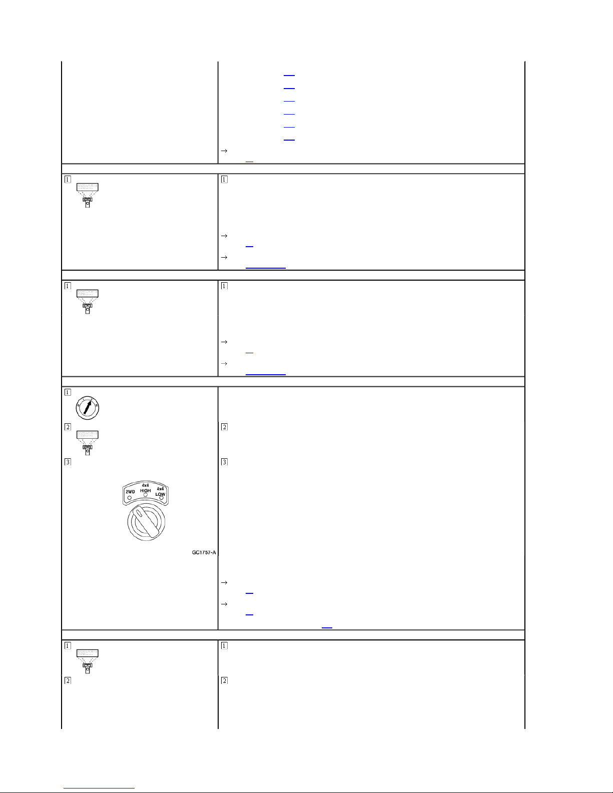
Place the mode switch in the 2WD position.
Does the PID indicate 2WD?
Yes
GO to A6.
No
GO to A8.
A6 CHECK THE 4X4 MODE SW ITCH — MONITOR THE GEM PID 4WD_SW IN THE 4X4 HI GH POSITION
Place the mode switch in the 4X4 HIGH position.
If the PID indicates OFFO-G, GO to A14 .
Monitor the GEM PID 4WD_SW .
Page 9
Page
9
of 622000 Ranger Workshop Manual
1/18/2012
http://www.fordtechservice.dealerconnection.com/pubs/content/~WSYL/~MUS~LEN/21/
...
Does the PID indicate 4WD HIG H?
Yes
GO to A7.
No
A7 CHECK THE 4X4 MODE SW ITCH — MONITOR THE GEM PID 4WD_SW
A8 CHECK THE 4X4 MODE SW ITCH IN THE 2WD POSITION
GO to A8.
Monitor the GEM PID 4WD_SW .
Place the mode switch in the 4X4 LOW position.
Does the PID indicate 4WD L OW?
Yes
GO to A16.
No
GO to A8.
If the PID indicates OFFO-G, GO to A14 .
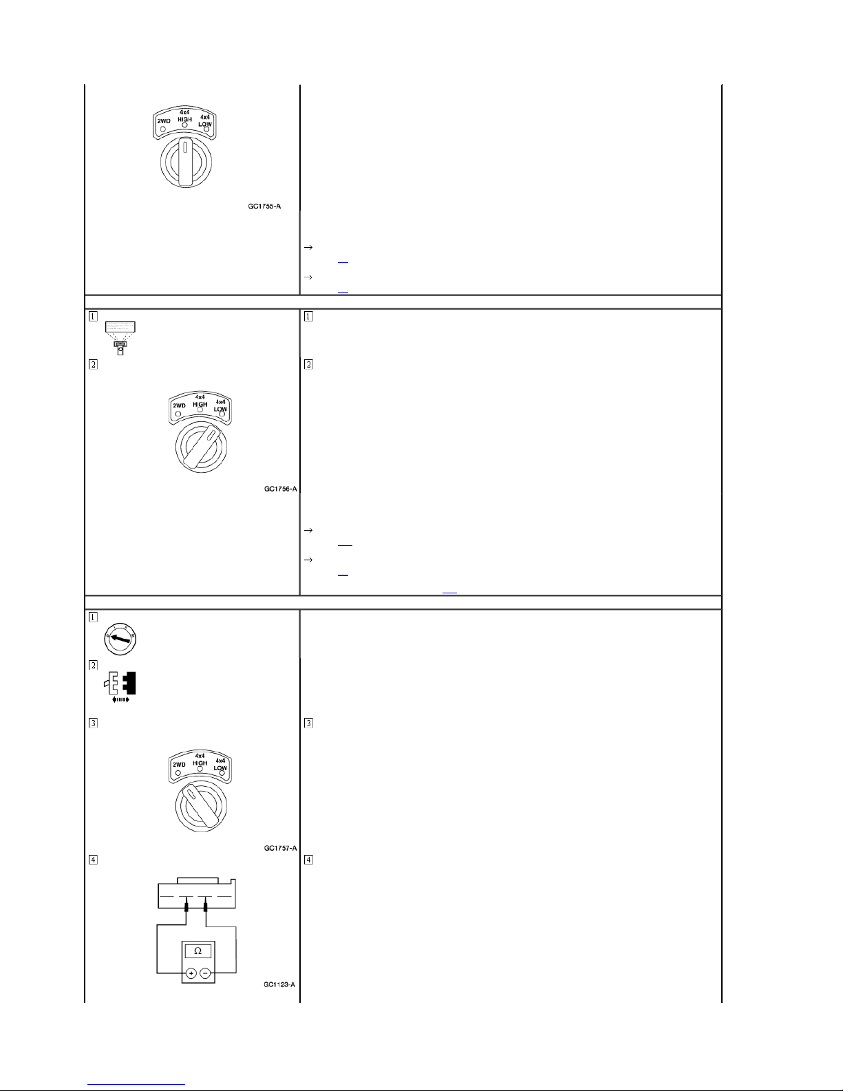
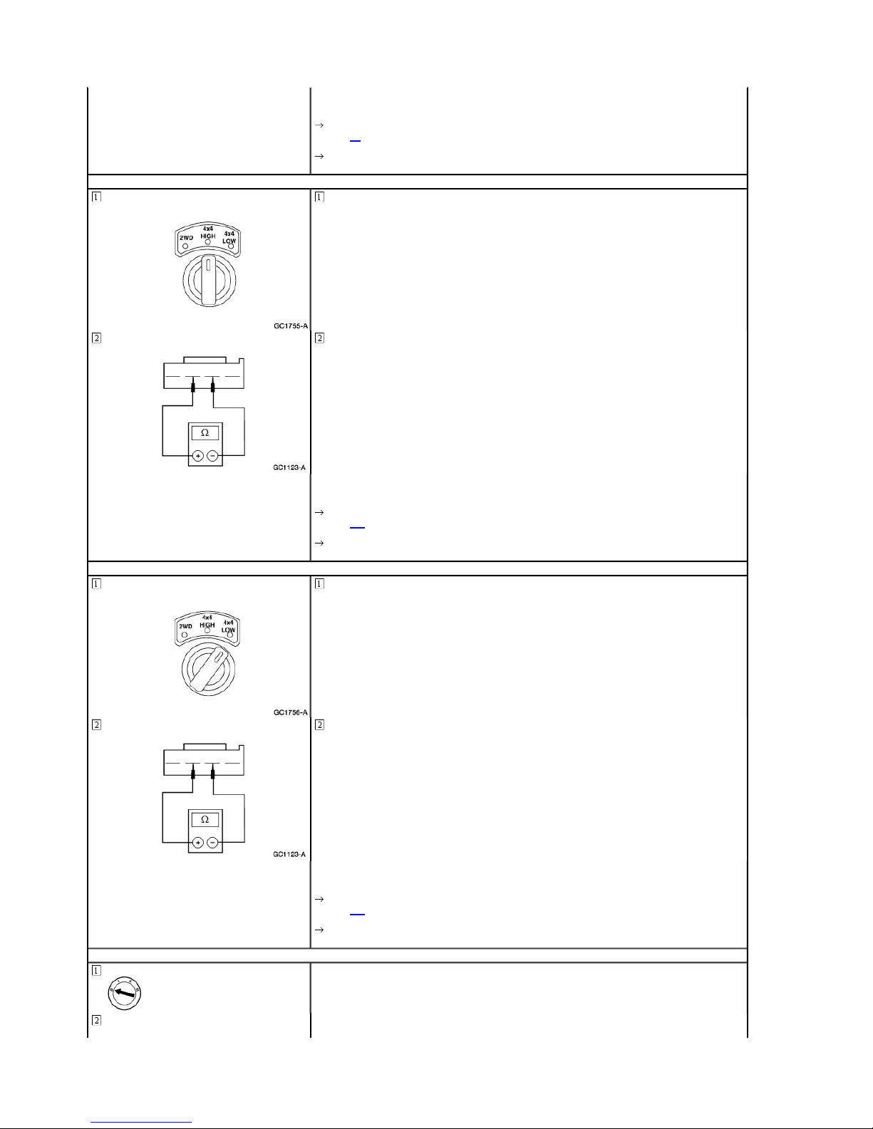
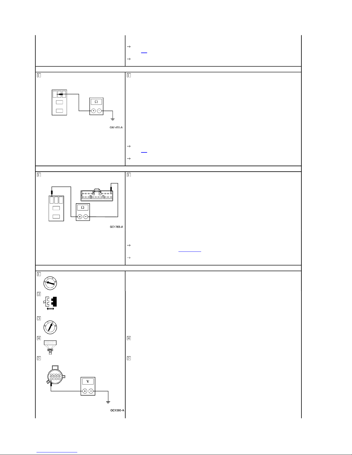
4X4 Mode Switch C225
Place the mode switch in the 2WD position.
Measure the resistance between the mode switch terminals 2 and 3.
Page 10
Page
10
of 622000 Ranger Workshop Manual
1/18/2012
http://www.fordtechservice.dealerconnection.com/pubs/content/~WSYL/~MUS~LEN/21/
...
Yes
GO to A9.
No
A9 CHECK THE 4X4 MODE SW ITCH IN THE 4X4 HIGH POSI TION
REPLACE the mode switch. CLEAR the DTCs. TEST the sy stem for normal operation.
Place the mode switch in the 4X4 HIGH position.
Is the resistance between 3700 and 4100 ohms?
A10 CHECK THE 4X4 MODE SWITCH IN THE 4X4 LOW POSI TION
Measure the resistance between the mode switch, terminals 2 and 3.
Yes
GO to A10.
No
REPLACE the mode switch. CLEAR the DTCs. TEST the sy stem for normal operation.
Place the mode switch in the 4X4 LOW position.
Measure the resistance between the mode switch, terminals 2 and 3.
Is the resistance between 1050 and 1150 ohms?
Is the resistance between 340 and 380 ohms?
Yes
GO to A11.
No
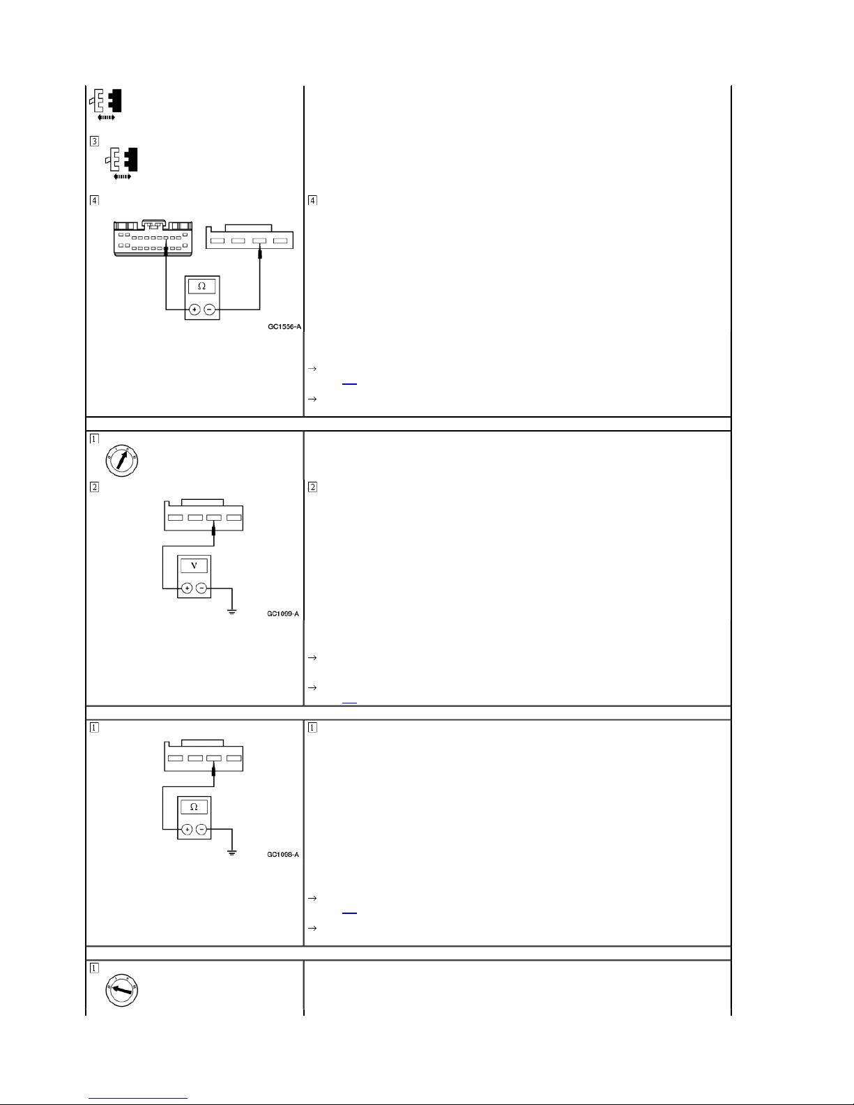
A11 CHECK CIRCUIT 465 (W/LB) FOR OPEN
REPLACE the mode switch. CLEAR the DTCs. TEST the sy stem for normal operation.
Page 11
Page
11
of 622000 Ranger Workshop Manual
1/18/2012
http://www.fordtechservice.dealerconnection.com/pubs/content/~WSYL/~MUS~LEN/21/
...
4X4 Mode Switch C225
GEM C223
A12 CHECK CIRCUIT 465 (W/LB) FOR SHORT TO POWER
Measure the resistance between mode switch C225-3, circuit 465 (W/LB), and GEM C223-8, circuit 465 (W/LB).
Is the resistance less than 5 ohms?
Yes
GO to A12.
No
REPAIR circuit 465 (W/LB). CLEAR the DTCs. TEST the system for normal operation.
Measure the voltage between mode switch C225-3, circuit 465 (W/LB), and ground.
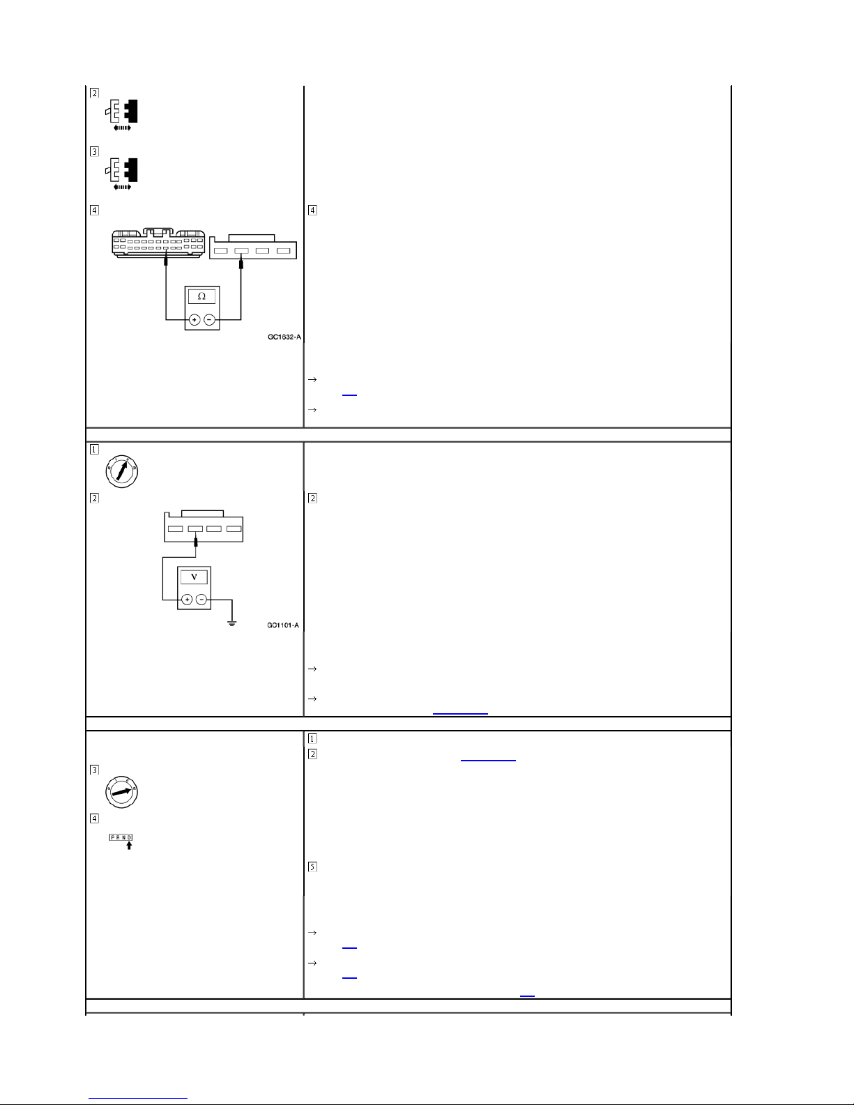
A13 CHECK CIRCUIT 465 (W/LB) FOR SHORT TO GROUND
A14 CHECK CIRCUIT 359 (GY/ R) FOR OPEN
Is any voltage indicated?
Yes
REPAIR circuit 465 (W/LB). CLEAR the DTCs. TEST the system for normal operation.
No
GO to A13.
Measure the resistance between mode switch C225-3, circuit 465 (W/LB), and ground.
Is the resistance greater than 10,000 ohms?
Yes
GO to A14.
No
REPAIR circuit 465 (W/LB). CLEAR the DTCs. TEST the system for normal operation.
Page 12
Page
12
of 622000 Ranger Workshop Manual
1/18/2012
http://www.fordtechservice.dealerconnection.com/pubs/content/~WSYL/~MUS~LEN/21/
...
4X4 Mode Switch C225
GEM C221
A15 CHECK CIRCUIT 359 (GY/ R) FOR SHORT TO POWER
Measure the resistance between mode switch C225-2, circuit 359 (GY/R), and GEM C221-21, circuit 359 (GY/R).
Is the resistance less than 5 ohms?
Yes
GO to A15.
No
REPAIR circuit 359 (GY/R). CLEAR the DTCs. TEST the system for normal operation.
Measure the voltage between mode switch C225-2, circuit 359 (GY/R), and ground.
A16 CHECK THE FRONT DR IVESHAFT ENGAGEMENT
A17 CHECK THE FRONT DR IVESHAFT DISENGAGEMENT
Is any voltage indicated?
Yes
REPAIR circuit 359 (GY/R). CLEAR the DTCs. TEST the system for normal operation.
No
REPLACE the GEM; REFER to Section 419-10. CLEAR the DTCs. TEST the system for no rmal operation.
Engage 4X4 HIGH and drive a short distance.
Raise and support the vehicle; refer to Section 100-02.
NOTE: The front and rear driveshafts should both spin.
Observe the front and rear driveshafts.
Does the transfer case lock the front driveshaft to the rear driveshaft?
Yes
GO to A17.
No
GO to A41.
If 4WD engagement is prolonged, harsh or noisy, GO to A18 .
Page 13
When 4X4 is disengaged, the front driveshaft may spin due to viscous drag in the transfer case, especially
A18 CHECK THE CLUTCH RE LAY
Page
13
of 622000 Ranger Workshop Manual
1/18/2012
http://www.fordtechservice.dealerconnection.com/pubs/content/~WSYL/~MUS~LEN/21/
...
Turn the 4X4 mode switch to the 2WD position.
NOTE:
if cold. If this occurs, the front drive line can easily be stopped.
Drive the vehicle in reverse for 10 feet (3 meters) to disengage the front hubs.
Does only the rear driveshaft spin?
Yes
GO to Pinpoint Test E.
No
If the front driveshaft is not working properly, GO to A41 .
A19 CHECK THE CLUTCH RE LAY COIL CIRCUIT — MONITOR THE GEM PID 4WDELCL
A20 CHECK CIRCUIT 275 (Y ) FOR SHORT TO POWER
Check the clutch relay; refer to Component Test.
Is the clutch relay OK?
Yes
RECONNECT the clutch relay. GO to A19 .
No
REPLACE the clutch relay. CLEAR the DTCs. TEST the sys tem for normal operation.
Trigger the GEM active command SHIFT CLUTCH to ON.
Monitor the GEM PID 4WDELC L.
Does the GEM PID 4WDELCL display ON---?
Yes
GO to A21.
No
If the PID displays ON-B-, GO to A20 .
Clutch Relay
GEM C223
Measure the voltage between clutch relay, connector pin 1, ci rcuit 275 (Y), and ground.
Page 14
Page
14
of 622000 Ranger Workshop Manual
1/18/2012
http://www.fordtechservice.dealerconnection.com/pubs/content/~WSYL/~MUS~LEN/21/
...
Is any voltage indicated?
Yes
REPAIR circuit 275 (Y). CLE AR the DTCs. TEST the system for normal operation.
No
A21 CHECK THE ELECTRIC S HIFT RELAY COIL CIRCUIT — MONITOR THE GEM PID 4WDELCL
REPLACE the GEM; REFER to Section 419-10. CLEAR the DTCs. TEST the system for no rmal operation.
Trigger the GEM active command SHIFT CLUTCH to OFF.
Monitor the GEM PID 4WDELC L.
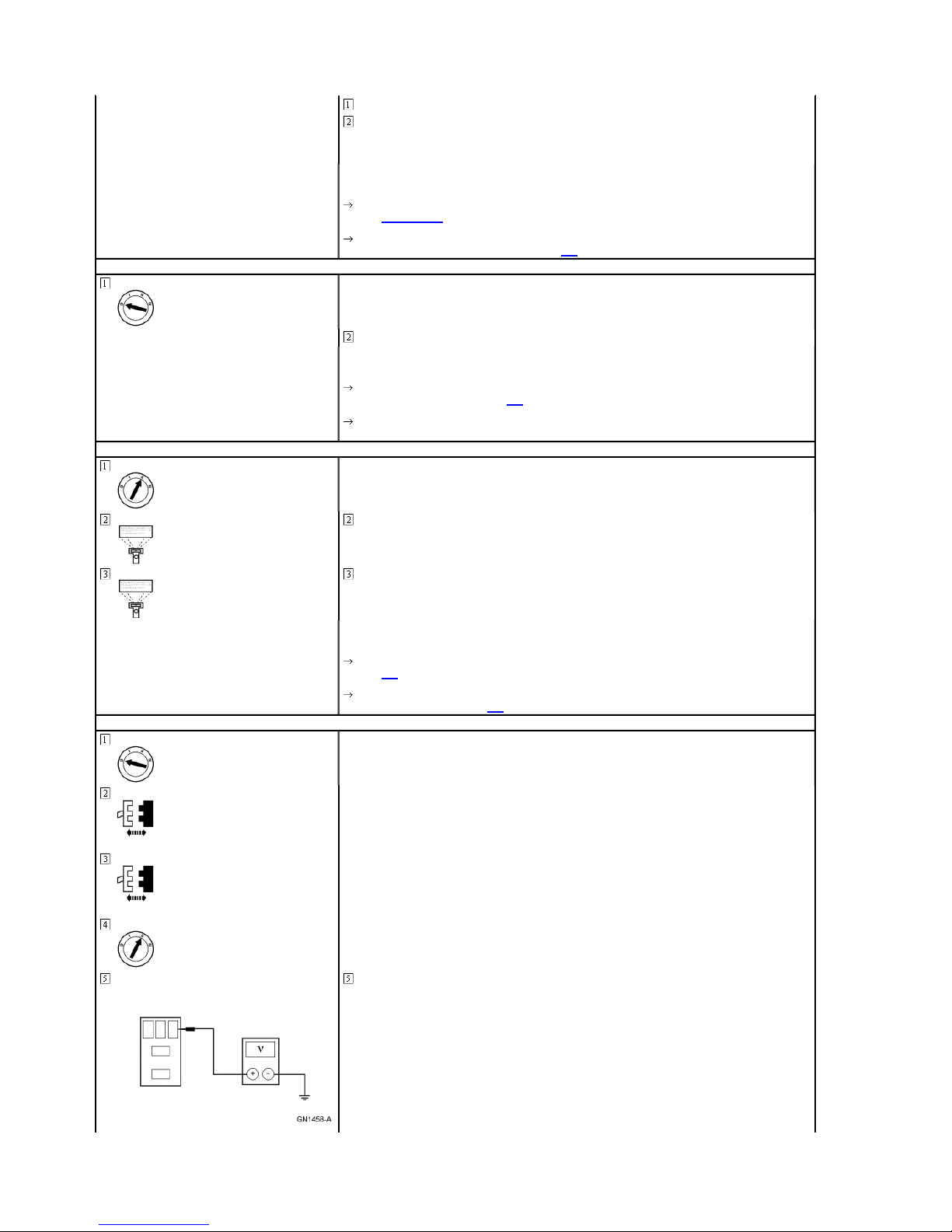
A22 CHECK THE BATTERY SA VER RELAY
A23 CHECK THE BATTERY SA VER RELAY COIL CIRCUIT — MONITOR THE GEM PID BAT T_SAVE
Battery Saver Relay
Does the GEM PID 4WDELCL display OFF--?
Yes
GO to A36.
No
If the PID displays OFFO-G, GO to A22 .
Check the battery saver relay; refer to Component Test.
Is the battery saver relay OK?
Yes
GO to A23.
No
REPLACE the battery saver relay. CLEAR the DTCs. TEST the system for normal operation.
Trigger the GEM active command BATT_SAVR to ON.
Monitor the GEM PID BATT_SAV R.
A24 CHECK CIRCUIT 1005 (P /O) FOR SHORT TO POWER
Battery Saver Relay
GEMC
Does the GEM PID BATT_SA VR display ON---?
Yes
GO to A25.
No
If the GEM PID BATT_SAVR displays ON-B-, GO to A24 .
Page 15
Page
15
of 622000 Ranger Workshop Manual
1/18/2012
http://www.fordtechservice.dealerconnection.com/pubs/content/~WSYL/~MUS~LEN/21/
...
A25 CHECK THE BATTERY SA VER RELAY COIL CIRCUIT — MONITOR THE GEM PID BAT T_SAVR
A26 CHECK FOR VOLTAGE TO THE BATTERY SAVER RELAY — CIRCUIT 792 (T/Y)
Measure the voltage between battery saver relay connector pin 2, circuit 1005 (P/O), and grou nd.
Is any voltage indicated?
Yes
REPAIR circuit 1005 (P/O). CLEAR the DTCs. TEST the system for normal operation.
No
REPLACE the GEM; REFER to Section 419-10. CLEAR the DTCs. TEST the system for no rmal operation.
Trigger the GEM active command BATT_SAVR to OFF.
Monitor the GEM PID BATT_SAV R.
Does the GEM PID BATT_SA VR display OFF---?
Yes
GO to A36.
No
If the GEM PID BATT_SAVR displays OFFO-G, GO to A26 .
Battery Saver Relay
A27 CHECK THE POWER O UTPUT FROM FUSE JUNCTION PANEL FUSE 26 (10A)
Measure the voltage between fuse 26 (10A) pin 1, and ground; and between fuse 26 (10A) pin 2, and ground.
Measure the voltage between battery saver relay connector pin 1, circuit 792 (T/Y), and groun d; and between
battery saver relay connector pin 5, circuit 792 (T/Y), and ground.
Are the voltages greater than 10 volts?
Yes
GO to A32.
No
GO to A27.
Page 16
Page
16
of 622000 Ranger Workshop Manual
1/18/2012
http://www.fordtechservice.dealerconnection.com/pubs/content/~WSYL/~MUS~LEN/21/
...
A28 CHECK FUSE JUNCTIO N PANEL FUSE 26 (10A)
Fuse 26 (10A)
A29 CHECK CIRCUIT 792 (T/Y ) FOR SHORT TO GROUND
Battery Saver Relay
Are the voltages greater than 10 volts?
Yes
REPAIR open in circuit 792 (T/Y). REPLACE the fuse. CLEAR the DTCs. TEST the system for normal operation.
No
GO to A28.
Is the fuse OK?
Yes
REPAIR the fuse junction pa nel. TEST the system for norma l operation.
No
GO to A29.
Measure the resistance between battery saver relay connec tor pin 1, circuit 792 (T/Y), and g round; and between
battery saver relay connector pin 5, circuit 792 (T/Y), and ground.
Are the resistances greater than 10,000 ohms?
Yes
GO to A30.
No
A30 CHECK CIRCUIT 705 (LG /O) FOR SHORT TO GROUND
Clutch Relay
J50 Relay
Measure the resistance between battery saver relay connec tor pin 3, circuit 705 (LG/O), and ground.
REPAIR circuit 792 (T/Y). TEST the system for normal operation.
Page 17
A31 CHECK CIRCUIT 705 (LG /O) FOR OPEN
Page
17
of 622000 Ranger Workshop Manual
1/18/2012
http://www.fordtechservice.dealerconnection.com/pubs/content/~WSYL/~MUS~LEN/21/
...
A32 CHECK CIRCUIT 275 (Y ) FOR OPEN
GEM C223
Is the resistance greater than 10,000 ohms?
Yes
GO to A31.
No
REPAIR circuit 705 (LG/O). TEST the system for normal operation.
Measure the resistance between battery saver relay connec tor pin 3, circuit 705 (LG/O), and clutch relay
connector pin 2, circuit 705 (LG/O ).
Is the resistance less than 5 ohms?
Yes
GO to A32.
No
REPAIR circuit 705 (LG/O). TEST the system for normal operation.
Measure the resistance between clutch relay connector pin 1, circuit 275 (Y), and GEM C223 -15, circuit 275 (Y).
Is the resistance less than 5 ohms?
Yes
GO to A33.
No
A33 CHECK CIRCUIT 275 (Y ) FOR SHORT TO GROUND
REPAIR circuit 275 (Y). TES T the system for normal operation.
Measure the resistance between clutch relay connector pin 1, circuit 275 (Y), and ground.
Page 18
A34 CHECK CIRCUIT 1005 (P /O) FOR SHORT TO GROUND
Page
18
of 622000 Ranger Workshop Manual
1/18/2012
http://www.fordtechservice.dealerconnection.com/pubs/content/~WSYL/~MUS~LEN/21/
...
A35 CHECK CIRCUIT 1005 (P /O) FOR OPEN
Is the resistance greater than 10,000 ohms?
Yes
GO to A34.
No
REPAIR circuit 275 (Y). TES T the system for normal operation.
Measure the resistance between battery saver relay connec tor pin 2, circuit 1005 (P/O), and ground.
Is the resistance greater than 10,000 ohms?
Yes
GO to A35.
No
REPAIR circuit 1005 (P/O). TEST the system for normal operation.
Measure the resistance between battery saver relay connec tor pin 2, circuit 1005 (P/O), and GEM C224-8, circuit
1005 (P/O).
Is the resistance less than 5 ohms?
Yes
REPLACE the GEM; REFER to Section 419-10. CLEAR the DTCs. TEST the system for no rmal operation.
No
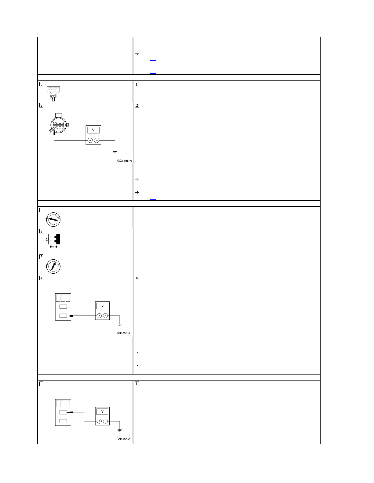
A36 CHECK CIRCUIT 779 (B R) FOR VOLTAGE — GEM AC TIVE COMMAND SHIFT CLUTC H ON
Transfer Case Electric Shift Motor C1001
REPAIR circuit 1005 (P/O). TEST the system for normal operation.
Trigger the GEM active command SHIFT CLUTCH to ON.
Measure the voltage between transfer case electric shift motor C1001-8, circuit 779 (BR), a nd ground.
Page 19
Page
19
of 622000 Ranger Workshop Manual
1/18/2012
http://www.fordtechservice.dealerconnection.com/pubs/content/~WSYL/~MUS~LEN/21/
...
Is the voltage greater than 10 volts?
Yes
GO to A37.
No
A37 CHECK CIRCUIT 779 (B R) FOR VOLTAGE — GEM AC TIVE COMMAND SHIFT CLUTC H OFF
A38 CHECK CIRCUIT 779 (B R) FOR SHORT TO POWER
GO to A38.
Trigger the GEM active command SHIFT CLUTCH to OFF.
Measure the voltage between transfer case electric shift motor C1001-8, circuit 779 (BR), a nd ground.
Is the voltage zero volts?
Yes
REPLACE the clutch relay. CLEAR the DTCs. TEST the sys tem for normal operation.
No
GO to A38.
Clutch Relay
A39 CHECK THE CLUTCH RE LAY SWITCHING CIRCUIT
Measure the voltage between the clutch relay connector pin 3, circuit 779 (BR), and ground.
Is any voltage indicated?
Yes
REPAIR circuit 779 (BR). CLEA R the DTCs. TEST the system for normal operation.
No
GO to A39.
Measure the voltage between clutch relay connector pin 5, c ircuit 704 (DG/LG), and ground.
Page 20

Page
20
of 622000 Ranger Workshop Manual
1/18/2012
http://www.fordtechservice.dealerconnection.com/pubs/content/~WSYL/~MUS~LEN/21/
...
Is the voltage greater than 10 volts?
Yes
GO to A40.
No
CHECK power distribution box mini-fuse 3 (20A). REPLACE if necessary. If OK, REPAIR circuit 704 (DG/LG).
A40 CHECK CIRCUIT 779 (B R) FOR OPEN
A41 CHECK THE ELECTRONI C SHIFT CONTROL MODULE — GEM ACTIVE COMMAND CW/CCW ON
CLEAR the DTCs. TEST the system for normal operation.
Measure the resistance between clutch relay connector pin 3, circuit 779 (BR), and transfer case electric shift
motor C1001-8, circuit 779 (BR).
Is the resistance less than 5 ohms?
Yes
REPLACE the clutch relay. CLEAR the DTCs. TEST the sys tem for normal operation.
No
REPAIR circuit 779 (BR). CLEA R the DTCs. TEST the system for normal operation.
Trigger the GEM active command CW/CCW to ON.
Monitor the GEM PIDs MTR_CCW and MTR_CW.
A42 CHECK THE ELECTRONI C SHIFT CONTROL MODULE — GEM ACTIVE COMMAND CW/CCW OFF
A43 CHECK THE VOLTAGE TO THE ELECTRONIC SHIFT CONTROL MODULE COILS — CIRCUIT 705 (LG/O)
JSO Relay C230
Measure the voltage between JSO relay C230-5, circuit 705 (LG/O), and ground.
Do/Does the GEM PIDs MTR_C CW and MTR_CW display ON?
Yes
GO to A42.
No
If the PID(s) display(s) ON-B -, GO to A47 .
Trigger the GEM active command CW/CCW to OFF.
Do/Does the GEM PIDs MTR_C CW and MTR_CW display OFF?
Yes
GO to A50.
No
If the PID displays OFFO-G, GO to A43 .
Page 21

A44 CHECK CIRCUIT 513 (B R/PK) FOR OPEN
Page
21
of 622000 Ranger Workshop Manual
1/18/2012
http://www.fordtechservice.dealerconnection.com/pubs/content/~WSYL/~MUS~LEN/21/
...
GEM C223
A45 CHECK CIRCUIT 339 (GY) FOR OPEN
Is the voltage greater than 10 volts?
Yes
GO to A44.
No
REPAIR circuit 705 (LG/O). CLEAR the DTCs. TEST the syst em for normal operation.
Measure the resistance between JSO relay C230-9, circuit 513 (BR/PK), and GEM C223-17, circuit 513 (BR/PK).
Is the resistance less than 5 ohms?
Yes
GO to A45.
No
REPAIR circuit 513 (BR/PK) . CLEAR the DTCs. TEST the sy stem for normal operation.
Measure the resistance between JSO relay C230-8, circuit 339 (GY), and GEM C223-16, circuit 339 (GY).
Is the resistance less than 5 ohms?
Yes
GO to A46.
No
A46 CHECK CIRCUITS 513 (BR/PK) AND 339 (GY) FOR SH ORT TO GROUND
REPAIR circuit 339 (GY). CLEAR the DTCs. TEST the system for normal operation.
Measure the resistance between JSO relay C230-8, circuit 339 (GY), and ground; and betw een ISO relay C2309, circuit 513 (BR/PK), and ground.
Are the resistances greater than 10,000 ohms?
Page 22

A47 CHECK CIRCUIT 339 (GY) FOR SHORT TO POWER
Page
22
of 622000 Ranger Workshop Manual
1/18/2012
http://www.fordtechservice.dealerconnection.com/pubs/content/~WSYL/~MUS~LEN/21/
...
JSO Relay C230
GEM C223
Yes
GO to A49.
No
REPAIR circuit 513 (BR/PK) and/or circuit 339 (GY). CLEAR the DTCs. TEST the system for normal operation.
Measure the voltage between JSO relay C230-8, circuit 339 (GY), and ground.
Yes
REPAIR circuit 339 (GY). CLEAR the DTCs. TEST the system for normal operation.
No
A48 CHECK CIRCUIT 513 (B R/PK) FOR SHORT TO POWER
A49 CHECK THE ELECTRONI C SHIFT CONTROL MODULE COILS
GO to A48.
Measure the voltage between JSO relay C230-9, circuit 513 (BR/PK), and ground.
Yes
REPAIR circuit 513 (BR/PK) . CLEAR the DTCs. TEST the sy stem for normal operation.
No
GO to A49.
Measure the resistance between the JSO relay terminal 5 and terminals 8, 9.
Is any voltage indicated?
Is any voltage indicated?
Page 23

Page
23
of 622000 Ranger Workshop Manual
1/18/2012
http://www.fordtechservice.dealerconnection.com/pubs/content/~WSYL/~MUS~LEN/21/
...
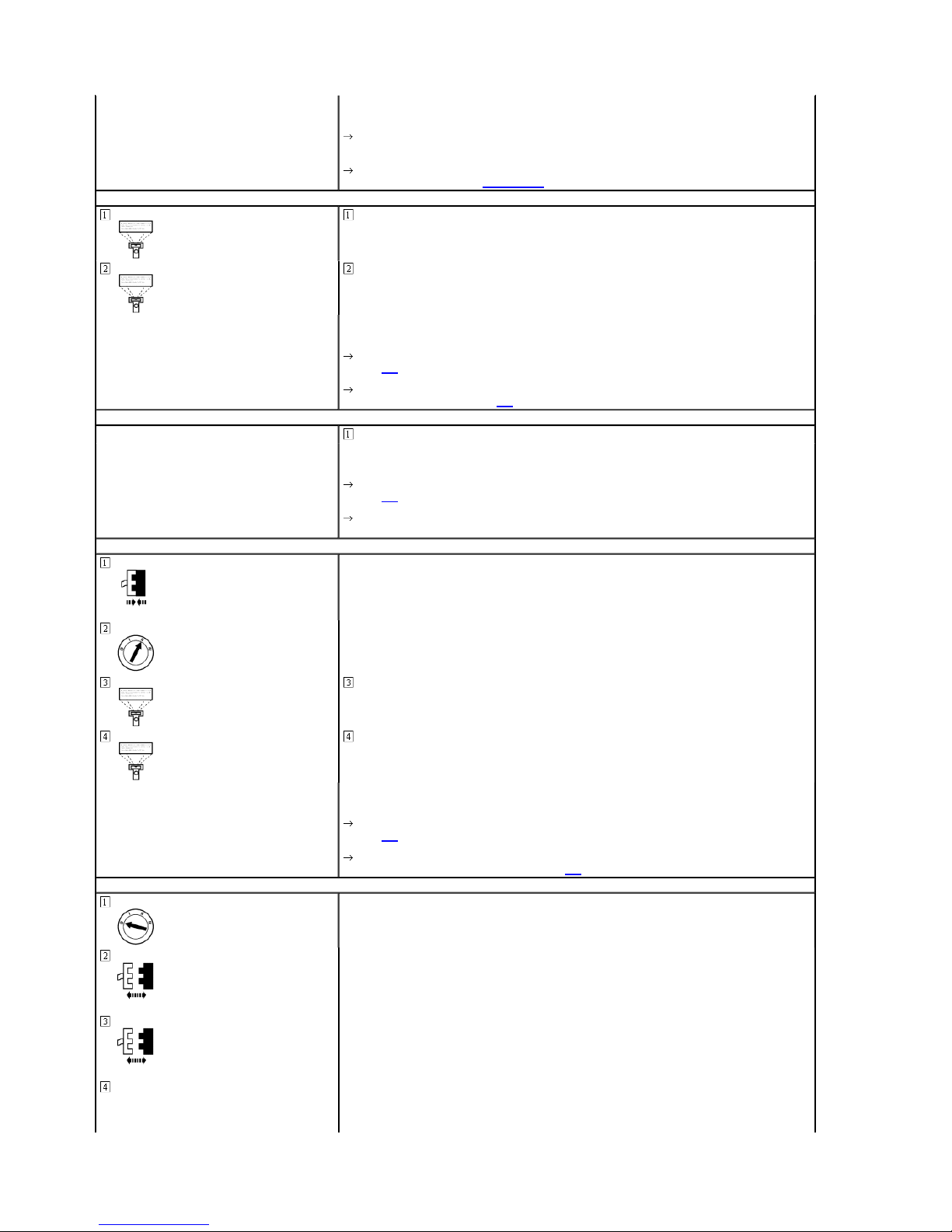
Are the resistance(s) between 60 and 110 ohms?
Yes
REPLACE the GEM; REFER to Section 419-10. CLEAR the DTCs. TEST the system for no rmal operation.
No
A50 CHECK THE VOLTAGE TO THE ELECTRIC SHIFT MO TOR — GEM ACTIVE COMMAND CW/CCW ON
Transfer Case Electric Shift Motor C1001
REPLACE the JSO relay. CLEAR the DTCs. TEST the system for normal operation.
Trigger the GEM active command CW/CCW to ON.
Measure the voltage between transfer case electric shift motor C1001-7, circuit 778 (O), and ground; and
between transfer case electric sh ift motor C310-4, circuit 7 77 (Y), and ground.
Are the voltages greater than 10 volts?
Yes
GO to A52.
No
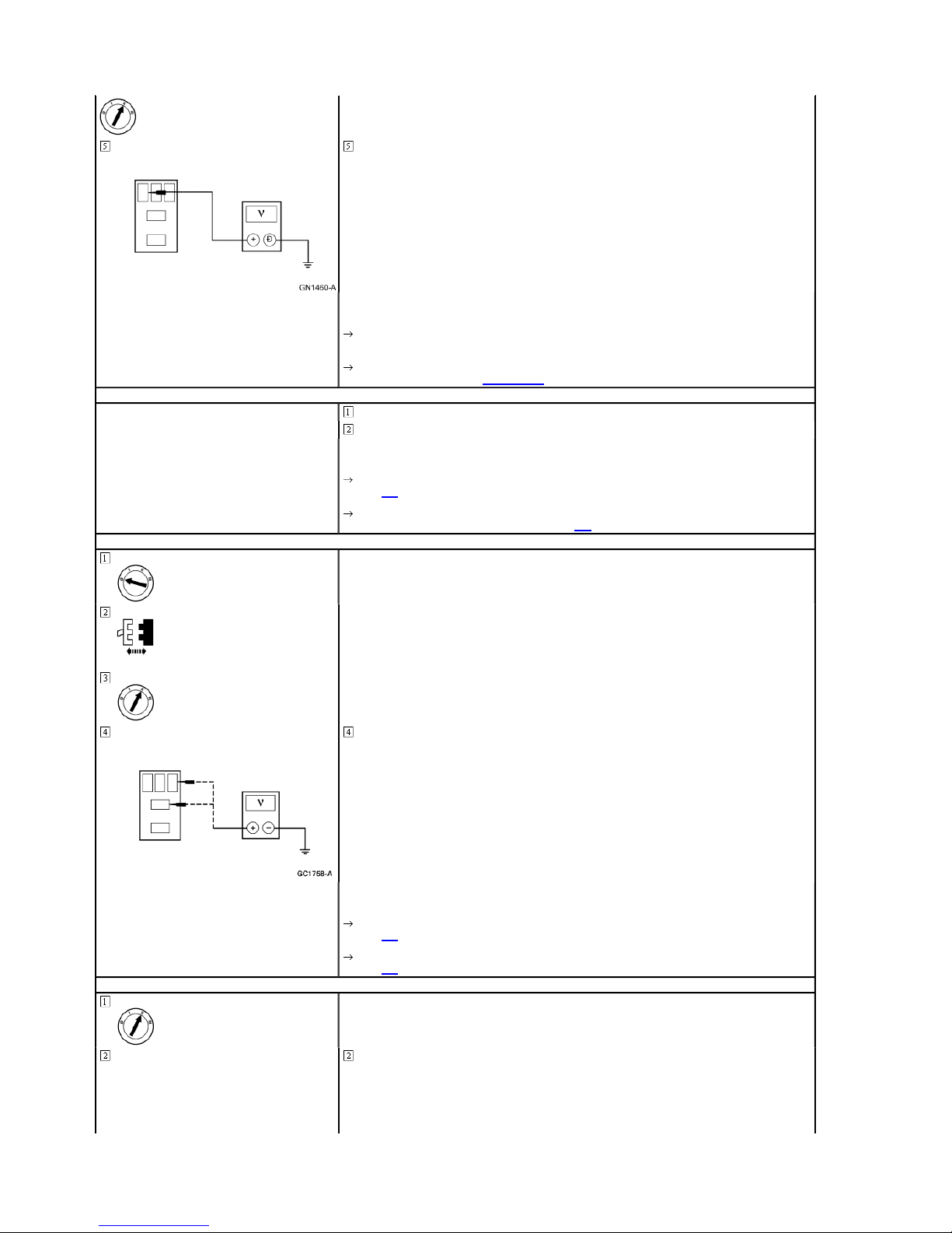
A51 CHECK THE VOLTAGE TO THE ELECTRONIC SHIFT CONTROL MODULE SWITCH — CIRCUIT 704 (DG/LG)
JSO Relay C230
A52 CHECK THE VOLTAGE TO THE ELECTRIC SHIFT MO TOR — GEM ACTIVE COMMAND CW/CCW OFF
GO to A51.
Measure the voltage between JSO relay C230-3, circuit 704 (DG/LG), and ground.
Is the voltage greater than 10 volts?
Yes
GO to A55.
No
CHECK power distribution box fuse 3 (20A). If OK, REPAIR circuit 704 (DG/LG). CLEAR the DTCs. TEST the
system for normal operation.
Page 24

4, circuit 777 (Y), and ground; and between
4, circuit 777 (Y), and ground; and between
Page
24
of 622000 Ranger Workshop Manual
1/18/2012
http://www.fordtechservice.dealerconnection.com/pubs/content/~WSYL/~MUS~LEN/21/
...
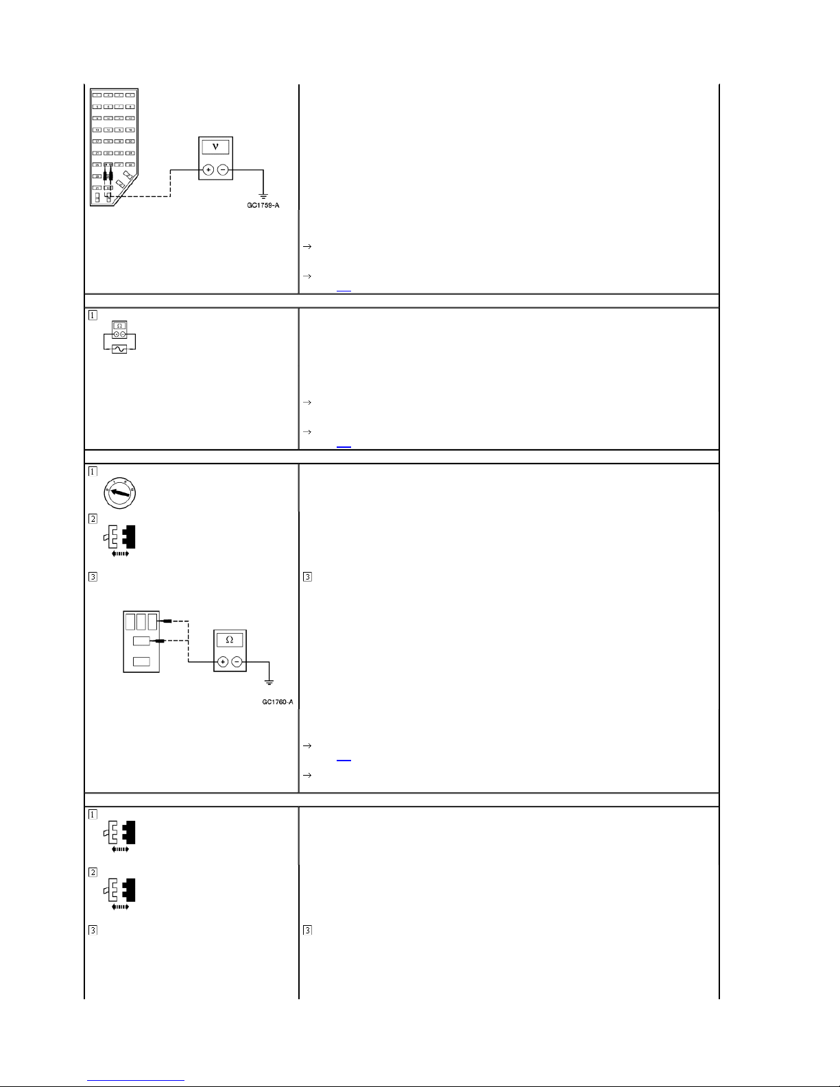
A53 CHECK CIRCUITS 777 (Y) AND 778 (O) FOR SHORT T O POWER
JSO Relay C230
Trigger the GEM active command CW/CCW to OFF.
Measure the voltage between transfer case electric shift motor C1001transfer case electric shift motor C1001-7, circuit 778 (O), and ground.
Are the voltages greater than 10 volts?
Yes
GO to A53.
No
GO to A54.
A54 CHECK CIRCUITS 777 (Y) AND 778 (O) FOR OPEN — GEM ACTIVE COMMAND CW/CC W OFF
Measure the voltage between transfer case electric shift motor C1001transfer case electric shift motor C1001-7, circuit 778 (O), and ground.
Is any voltage indicated?
Yes
REPAIR circuit 778 (O) and/ or circuit 777 (Y). CLEAR the DTCs. TEST the system for norma l operation.
No
REPLACE the JSO relay. CLEAR the DTCs. TEST the system for normal operation.
Trigger the GEM active command CW/CCW to OFF.
Measure the resistance between transfer case electric shift motor C1001-4, circuit 777 (Y), and ground; and
between transfer case electric sh ift motor, C1001-7, circuit 778 (O), and ground.
Page 25

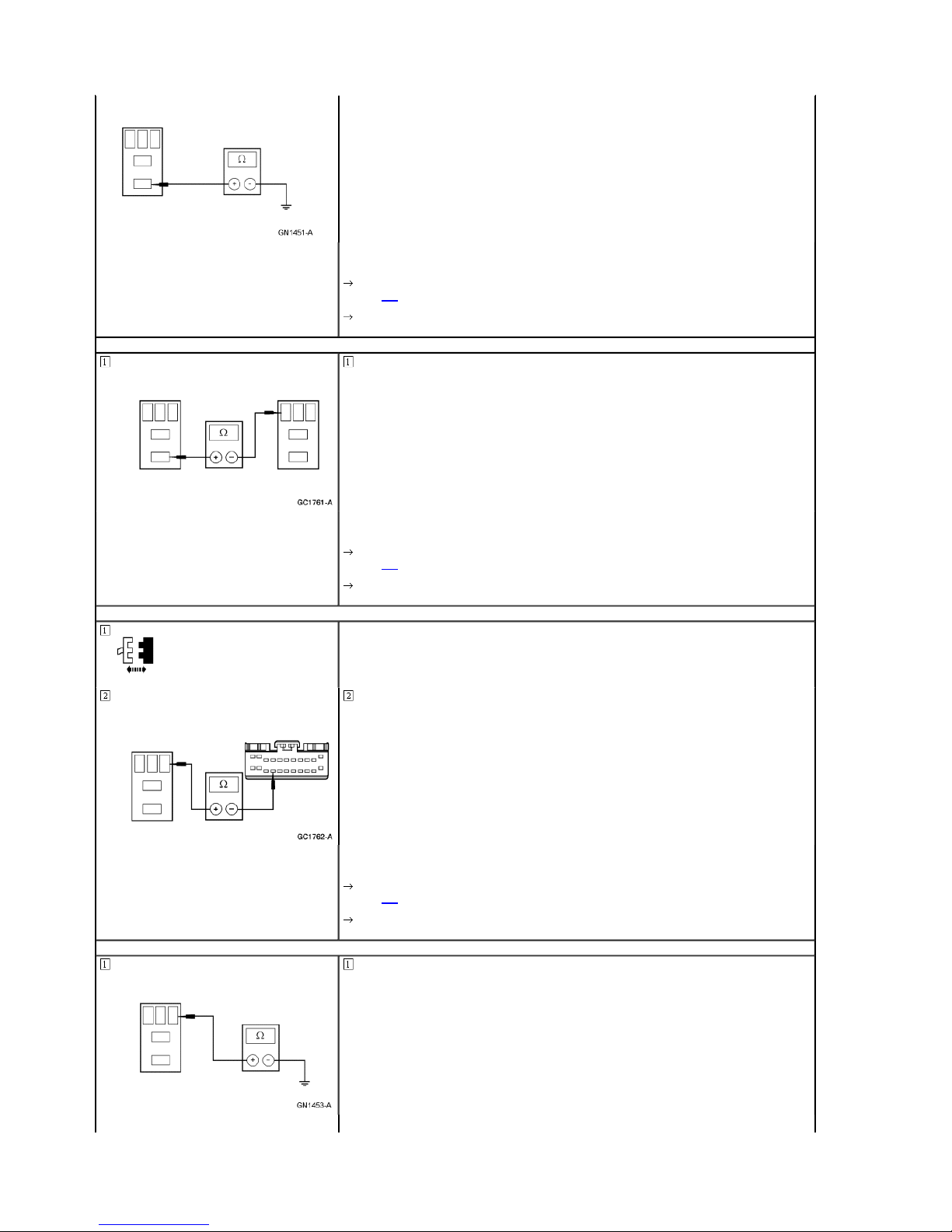
A55 CHECK CIRCUIT 777 (Y ) FOR OPEN
Page
25
of 622000 Ranger Workshop Manual
1/18/2012
http://www.fordtechservice.dealerconnection.com/pubs/content/~WSYL/~MUS~LEN/21/
...
JSO Relay C230
A56 CHECK CIRCUIT 778 (O) FOR OPEN
Are the resistances less than 5 ohms?
Yes
RECONNECT the transfer case electric shift motor. GO to A 58 .
No
GO to A57.
Measure the resistance between JSO relay, C230-7, circuit 777 (Y), and transfer case elec tric shift motor C10014, circuit 777 (Y).
Is the resistance less than 5 ohms?
Yes
GO to A56.
No
REPAIR circuit 777 (Y). CLE AR the DTCs. TEST the system for normal operation.
Measure the resistance between JSO relay C230-10, circuit 778 (O), and transfer case elect ric shift motor C10017, circuit 778 (O).
Is the resistance less than 5 ohms?
Yes
GO to A57.
No
A57 CHECK THE GROUND T O THE ELECTRONIC SHIFT CONTROL MODULE
JSO Relay C230
REPAIR circuit 778 (O). CLEAR the DTCs. TEST the system for normal operation.
Measure the resistance between JSO relay C230-1, circuit 57 (BK), and ground.
Page 26

Page
26
of 622000 Ranger Workshop Manual
1/18/2012
http://www.fordtechservice.dealerconnection.com/pubs/content/~WSYL/~MUS~LEN/21/
...
Is the resistance less than 5 ohms?
Yes
REPLACE the JSO relay. CLEAR the DTCs. TEST the system for normal operation.
No
A58 CHECK THE CONTACT PLATE SWITCHES — MONITOR THE GEM PLATE PIDS
REPAIR circuit 57 (BK). CLEAR the DTCs. TEST the system for normal operation.
Monitor GEM PIDs PLATE_A, PLATE_B, PLATE_C, and PLAT E_D.
Place the mode switch to 2WD and record the PID values.
Depress brake pedal.
Place the mode switch to 4X4 LOW and record the PID values.
A59 CHECK CONTACT PLAT E SWITCH D — CIRCUITS 771 (P/Y) AND 762 (Y/W)
Transfer Case Electric Shift Motor C1001
Connect a jumper wire between transfer case electric shift m otor C1001-6, circuit 762 (Y/W) , and C1001-5, circuit
Compare the PIDs with the following table.
PID 2WD 4WDLOW
PLATE_A Closed Closed
PLATE_B Closed Open
PLATE_C Open Closed
PLATE_D Closed Open
Do the PIDs agree with the ta ble?
Yes
REPAIR the transfer case; RE FER to Section 308-07B. CLEA R the DTCs. TEST the system for normal operation.
No
GO to A59.
Monitor the GEM PID PLATE_D, verify the PID indicates open.
771 (P/Y).
Page 27

Page
27
of 622000 Ranger Workshop Manual
1/18/2012
http://www.fordtechservice.dealerconnection.com/pubs/content/~WSYL/~MUS~LEN/21/
...
A60 CHECK CIRCUIT 771 (P /Y) FOR SHORT TO POWER
Transfer Case Electric Shift Motor C1001
GEM C223
Does the GEM PID PLATE_D ch ange states?
Yes
GO to A62.
No
GO to A60.
Measure the voltage between transfer case electric shift motor C1001-5, circuit 771 (P/Y), and ground.
A61 CHECK CIRCUIT 771 (P /Y) FOR SHORT TO GROUND
GEM C223
Is the voltage greater than 10 volts?
Yes
REPAIR circuit 771 (P/Y). CLEAR the DTCs. TEST the system for normal operation.
No
GO to A61.
Measure the resistance between transfer case electric shift motor C1001-5, circuit 771 (P/Y), and ground.
Is the resistance greater than 10,000 ohms?
Yes
Page 28

A62 CHECK CIRCUIT 771 (P /Y) FOR OPEN
Page
28
of 622000 Ranger Workshop Manual
1/18/2012
http://www.fordtechservice.dealerconnection.com/pubs/content/~WSYL/~MUS~LEN/21/
...
A63 CHECK CIRCUIT 762 (Y /W) FOR OPEN
GO to A62.
No
REPAIR circuit 771 (P/Y). CLEAR the DTCs. TEST the system for normal operation. If the concern remains,
RECONNECT GEM C223. GO to A64 .
Measure the resistance between transfer case electric shift motor C1001-5, circuit 771 (P/Y), and GEM C223-21,
circuit 771 (P/Y).
Is the resistance less than 5 ohms?
Yes
GO to A63.
No
REPAIR circuit 771 (P/Y). CLEAR the DTCs. TEST the system for normal operation.
Measure the resistance between transfer case electric shift motor C1001-6, circuit 762 (Y/W), and GEM C223-12,
circuit 762 (Y/W).
Is the resistance less than 5 ohms?
Yes
GO to A64.
No
A64 CHECK CONTACT PLAT E SWITCH C — CIRCUITS 762 (Y/W) AND 770 (W)
A65 CHECK CIRCUIT 770 (W) FOR SHORT TO POWER
REPAIR circuit 762 (Y/W). CLEAR the DTCs. TEST the syst em for normal operation.
Monitor the GEM PID PLATE_C. Verify the PID indicates open.
Connect a jumper wire between transfer case electric shift m otor C1001-6, circuit 762 (Y/W) , and C1001-1, circuit
770 (W).
Does the GEM PID PLATE_C ch ange states?
Yes
GO to A67.
No
GO to A65.
Page 29

Transfer Case Electric Shift Motor C1001
Page
29
of 622000 Ranger Workshop Manual
1/18/2012
http://www.fordtechservice.dealerconnection.com/pubs/content/~WSYL/~MUS~LEN/21/
...
GEM C223
A66 CHECK CIRCUIT 770 (W) FOR SHORT TO GROUND
Measure the voltage between transfer case electric shift motor C1001-1, circuit 770 (W), and ground.
Is any voltage indicated?
Yes
REPAIR circuit 770 (W). CLEAR the DTC. TEST the system for normal operation.
No
GO to A66.
Measure the resistance between transfer case electric shift motor C1001-1, circuit 770 (W), and ground.
Is the resistance greater than 10,000 ohms?
Yes
GO to A67.
No
REPAIR circuit 770 (W). CLEAR the DTCs. TEST the system for normal operation. If the concern remains,
A67 CHECK CIRCUIT 770 (W) FOR OPEN
A68 CHECK CONTACT PLAT E SWITCH B — CIRCUITS 762 (Y/W) AND 764 (BR/W)
Monitor the GEM PID PLATE_B.
RECONNECT GEM C223. GO to A67 .
Measure the resistance between transfer case electric shift motor C1001-1, circuit 770 (W), and GEM C223-20,
circuit 770 (W).
Is the resistance less than 5 ohms?
Yes
GO to A68.
No
REPAIR circuit 770 (W). CLEAR the DTCs. TEST the system for normal operation.
Page 30

Page
30
of 622000 Ranger Workshop Manual
1/18/2012
http://www.fordtechservice.dealerconnection.com/pubs/content/~WSYL/~MUS~LEN/21/
...
A69 CHECK CIRCUIT 764 (B R/W) FOR SHORT TO POWER
Transfer Case Electric Shift Motor C1001
GEM C223
Connect a jumper wire between transfer case electric shift m otor C1001-6, circuit 762 (Y/W) , and C1001-2, circuit
764 (BR/W).
Does the GEM PID PLATE_B ch ange states?
Yes
GO to A71.
No
GO to A69.
Measure the voltage between transfer case electric shift motor C1001-2, circuit 764 (BR/W), and ground.
A70 CHECK CIRCUIT 764 (B R/W) FOR SHORT TO GROUND
Is any voltage indicated?
Yes
REPAIR circuit 764 (BR/W). CLEAR the DTCs. TEST the system for normal operation.
No
GO to A70.
Measure the resistance between transfer case electric shift motor C1001-2, circuit 764 (BR/ W), and ground.
Is the resistance greater than 10,000 ohms?
Yes
GO to A71.
Page 31

Page
31
of 622000 Ranger Workshop Manual
1/18/2012
http://www.fordtechservice.dealerconnection.com/pubs/content/~WSYL/~MUS~LEN/21/
...
No
REPAIR circuit 764 (BR/W). CLEAR the DTCs. TEST the system for normal operation. If the concern remains,
A71 CHECK CIRCUIT 764 (B R/W) FOR OPEN
A72 CHECK CONTACT PLAT E SWITCH A — CIRCUITS 762 (Y/W) AND 763 (O/W)
RECONNECT GEM C223. GO to A72 .
Measure the resistance between transfer case electric shift motor C1001-2, circuit 764 (BR/ W), and GEM C23319, circuit 764 (BR/W).
Is the resistance less than 5 ohms?
Yes
GO to A72.
No
REPAIR circuit 764 (BR/W). CLEAR the DTCs. TEST the system for normal operation.
Monitor the GEM PID PLATE_A. Verify the PID indicates open.
Connect a jumper wire between transfer case electric shift m otor C1001-6, circuit 762 (Y/W) , and C1001-3, circuit
763 (O/W).
Does the GEM PID PLATE_A ch ange states?
Yes
GO to A75.
No
A73 CHECK CIRCUIT 763 (O/W ) FOR SHORT TO POWER
Transfer Case Electric Shift Motor C1001
GEM C223
Measure the voltage between transfer case electric shift motor C1001-3, circuit 763 (O/W), and ground.
GO to A73.
Page 32

Page
32
of 622000 Ranger Workshop Manual
1/18/2012
http://www.fordtechservice.dealerconnection.com/pubs/content/~WSYL/~MUS~LEN/21/
...
A74 CHECK CIRCUIT 763 (O/W ) FOR SHORT TO GROUND
A75 CHECK CIRCUIT 763 (O/W ) FOR OPEN
Is any voltage indicated?
Yes
REPAIR circuit 763 (O/W). CLEAR the DTC. TEST the system for normal operation.
No
GO to A74.
Measure the resistance between transfer case electric shift motor C1001-3, circuit 763 (O/W ), and ground.
Is the resistance greater than 10,000 ohms?
Yes
GO to A75.
No
REPAIR circuit 763 (O/W). CLEAR the DTCs. TEST the syst em for normal operation.
Measure the resistance between transfer case electric shift motor C1001-3, circuit 763 (O/W ), and GEM C223-18,
circuit 763 (O/W).
Is the resistance less than 5 ohms?
Yes
REPLACE the transfer case electric shift motor. CLEAR the DTCs. TEST the system for normal operation.
No
PINPOINT TEST B: THE VEHI CLE DOES NOT SHIFT BETWEEN 4WD HIGH AND 4WD LO W MODES PROPERLY
B1 CHECK THE IGNITION S TATES — MONITOR THE GEM PID IGN_GEM
CONDITIONS DETAILS/RESULTS/ACTIO NS
Scan Tool
REPAIR circuit 763 (O/W). CLEAR the DTCs. TEST the syst em for normal operation.
Page 33

Page
33
of 622000 Ranger Workshop Manual
1/18/2012
http://www.fordtechservice.dealerconnection.com/pubs/content/~WSYL/~MUS~LEN/21/
...
Monitor the GEM PID IGN_GEM while turning the ignition switch through the RUN, OFF and ACC positions.
B2 RETRIEVE THE DIAGNOST IC TROUBLE CODES (DTCS)
Clear Continuous DTCs
GEM On-Demand Self-Test
B3 CHECK THE 4X4 HIGH L AMP INDICATOR — TRIGGER THE GEM ACTIVE COMMAND HIGH LAMP ON
Do the PID values agree with the ignition switch positions?
Yes
GO to B2.
No
REFER to Section 417-02.
Retrieve and document continuous DTCs.
Are any DTCs recorded?
Yes
If DTC B1342, REPLACE the GEM; REFER to Section 419- 10. CLEAR the DTCs. TEST the system for normal
operation.
If DTC B1483, GO to B17 .
If DTC B1485, GO to B17 .
If DTC P0500 and the vehicl e is equipped with RABS, GO to B24 .
If DTC P0500 and the vehicl e is equipped with 4WABS, GO t o B27 .
If DTC P1812, GO to B5 .
If DTC P1815, GO to B5 .
No
GO to B3.
B4 CHECK THE 4X4 LOW LAMP INDICATOR — TRIGGER THE GEM ACTIVE COMMAND LO W LAMP ON
B5 CHECK THE 4X4 MODE SW ITCH — MONITOR THE GEM PID 4WD_SW IN 2WD POSIT ION
Place the mode switch in the 2WD position.
Trigger the GEM active command HIGH LAMP ON then OFF.
Does the 4x4 HIGH indicator illuminate then go off?
Yes
GO to B4.
No
GO to Pinpoint Test C.
Trigger the GEM active command LOW LAMP ON then OFF.
Does the 4x4 LOW indicator illuminate then go off?
Yes
Exit the GEM active command mode; GO to B5 .
No
GO to Pinpoint Test C.
Page 34

Page
34
of 622000 Ranger Workshop Manual
1/18/2012
http://www.fordtechservice.dealerconnection.com/pubs/content/~WSYL/~MUS~LEN/21/
...
Monitor the GEM PID 4WD_SW .
B6 CHECK THE 4X4 MODE SW ITCH — MONITOR THE GEM PID 4WD_SW IN THE 4X4 HI GH POSITION
B7 CHECK THE 4X4 MODE SW ITCH — MONITOR THE GEM PID 4WD_SW IN THE 4X4 LO W POSITION
Does the PID indicate 2WD?
Yes
GO to B6.
No
GO to B8.
If the PID indicates OFFO-G, GO to B14 .
Place the mode switch in the 4X4 HIGH position.
Monitor the GEM PID 4WD_SW .
Does the PID indicate 4WD HIG H?
Yes
GO to B7.
No
GO to B8.
Place the mode switch in the 4X4 LOW position.
B8 CHECK THE 4X4 MODE SW ITCH IN THE 2WD POSITION
Monitor the GEM PID 4WD_SW .
Does the PID indicate 4WD L OW?
Yes
GO to B17.
No
GO to B8.
Page 35

Page
35
of 622000 Ranger Workshop Manual
1/18/2012
http://www.fordtechservice.dealerconnection.com/pubs/content/~WSYL/~MUS~LEN/21/
...
4X4 Mode Switch C225
Place the mode switch in the 2WD position.
B9 CHECK THE 4X4 MODE SW ITCH IN THE 4X4 HIGH POSI TION
Measure the resistance between the mode switch terminals 2 and 3.
Yes
GO to B9.
No
REPLACE the mode switch. CLEAR the DTCs. TEST the sy stem for normal operation.
Place the mode switch in the 4X4 HIGH position.
Measure the resistance between the mode switch terminals 2 and 3.
Is the resistance between 3700 and 4100 ohms?
Is the resistance between 1050 and 1150 ohms?
Yes
GO to B10.
No
B10 CHECK THE 4X4 MODE SELECT SWITCH IN THE 4X4 LOW POSITION
Place the mode switch in the 4X4 LOW position.
REPLACE the mode switch. CLEAR the DTCs. TEST the sy stem for normal operation.
Page 36

Page
36
of 622000 Ranger Workshop Manual
1/18/2012
http://www.fordtechservice.dealerconnection.com/pubs/content/~WSYL/~MUS~LEN/21/
...
B11 CHECK CIRCUIT 465 (W/LB) FOR OPEN
GEM C223
4X4 Mode Switch C225
Measure the resistance between the mode switch terminals 2 and 3.
Is the resistance between 340 and 380 ohms?
Yes
GO to B11.
No
REPLACE the mode switch. CLEAR the DTCs. TEST the sy stem for normal operation.
Measure the resistance between mode switch C225-3, circuit 465 (W/LB), and GEM C223-8, circuit 465 (W/LB).
Is the resistance less than 5 ohms?
Yes
GO to B12.
No
B12 CHECK CIRCUIT 465 (W/LB) FOR SHORT TO POWER
Measure the voltage between GEM C223-8, circuit 465 (W/LB), an d ground.
REPAIR circuit 465 (W/LB). CLEAR the DTCs. TEST the system for normal operation.
Page 37

Page
37
of 622000 Ranger Workshop Manual
1/18/2012
http://www.fordtechservice.dealerconnection.com/pubs/content/~WSYL/~MUS~LEN/21/
...
B13 CHECK CIRCUIT 465 (W/LB) FOR SHORT TO GROUND
B14 CHECK CIRCUIT 359 (GY/ R) FOR OPEN
Is any voltage indicated?
Yes
REPAIR circuit 465 (W/LB). CLEAR the DTCs. TEST the system for normal operation.
No
GO to B13.
Measure the resistance between GEM C223-8, circuit 465 (W/LB), and ground.
Is the resistance greater than 10,000 ohms?
Yes
GO to B14.
No
REPAIR circuit 465 (W/LB). CLEAR the DTCs. TEST the system for normal operation.
GEM C221
B15 CHECK CIRCUIT 359 (GY/ R) FOR SHORT TO GROUND
Measure the resistance between GEM C221-21, circuit 359 (G Y/R), and ground.
Measure the resistance between mode switch C225-2, circuit 359 (GY/R), and GEM C221-21, circuit 359 (GY/R).
Is the resistance less than 5 ohms?
Yes
GO to B15.
No
REPAIR circuit 359 (GY/R). CLEAR the DTCs. TEST the system for normal operation.
Page 38

Page
38
of 622000 Ranger Workshop Manual
1/18/2012
http://www.fordtechservice.dealerconnection.com/pubs/content/~WSYL/~MUS~LEN/21/
...
Is the resistance greater than 10,000 ohms?
Yes
GO to B16.
No
B16 CHECK CIRCUIT 359 (GY/ R) FOR SHORT TO POWER
B17 CHECK BRAKE PEDAL POSITION (BPP) SWITCH — MONITOR THE GEM PID B OO_GEM
REPAIR circuit 359 (GY/R). CLEAR the DTCs. TEST the system for normal operation.
Measure the voltage between GEM C221-21, circuit 359 (GY/R), and ground.
Is the voltage greater than 10 volts?
Yes
REPAIR circuit 359 (GY/R). CLEAR the DTCs. TEST the system for normal operation.
No
REPLACE the GEM; REFER to Section 419-10. CLEAR the DTCs. TEST the system for no rmal operation.
Monitor GEM PID BOO_GEM.
B18 CHECK THE VOLTAGE TO THE BPP SWITCH — CIRCUIT 276 (BR)
BPP Switch C210
Depress the brake pedal.
Does the GEM PID BOO_GEM indicate ON?
Yes
GO to B20.
No
GO to B18.
Measure the voltage between BPP switch C210-3, circuit 276 (BR), and ground.
Page 39

B19 CHECK THE BPP SWITC H
Page
39
of 622000 Ranger Workshop Manual
1/18/2012
http://www.fordtechservice.dealerconnection.com/pubs/content/~WSYL/~MUS~LEN/21/
...
Is the voltage greater than 10 volts?
Yes
GO to B19.
No
CHECK fuse 9 (7.5A). REPLACE if necessary. If OK, REPA IR circuit 276 (BR). CLEAR the DTCs. TEST the
system for normal operation.
Monitor the GEM PID BOO_G EM.
B20 CHECK THE CLUTCH IN TERLOCK — MONITOR THE GEM PID CLTCHSW
Verify the GEM PID BOO_GEM indicates OFF.
Connect a jumper wire between the BPP switch C210-3, circuit 276 (BR), and C210-4, circuit 810 (R/LG).
Does the GEM PID BOO_GEM indicate ON?
Yes
REPLACE the BPP switch; REFER to Section 417-01. CLEAR the DTCs. TEST the system for normal operation.
No
REPAIR circuit 810 (R/LG). If OK, REPLACE the GEM; REFER to Section 419-10. CLEAR the DTCs. TEST the
system for normal operation.
Monitor the GEM PID CLTCH SW.
B21 CHECK THE TRANSMIS SION RANGE SENSOR PID NTRL_SW
Verify the GEM PID CLTCHSW indicates ENGAGED.
Place the gear selector in every position except neutral and pa rk.
Verify the GEM PID CLTCHSW indicates NOT ENGAGED.
Does the GEM PID CLTCHSW indicate correctly?
Yes
GO to B21.
No
DIAGNOSE the starter interrupt circuit and digital TR sensor. REFER to Section 303-06. If OK, REPLACE the
GEM; REFER to Section 419-10. CLEAR the DTCs. TEST the system for normal operation.
Monitor the GEM PID NTRL_SW.
Verify the GEM PID NTRL_SW indicates NTRL.
Place the gear selector in every position except neutral.
Verify the GEM PID NTRL_SW indicates notNRTL.
Page 40

Page
40
of 622000 Ranger Workshop Manual
1/18/2012
http://www.fordtechservice.dealerconnection.com/pubs/content/~WSYL/~MUS~LEN/21/
...
Does the GEM PID NTRL_SW indicate correctly?
Yes
GO to B24.
No
B22 CHECK THE GROUND T O THE DIGITAL TR SENSOR — CIRCUIT 57 (BK)
Digital TR Sensor C1005
B23 CHECK THE DIGITAL TR SENSOR — MONITOR THE GEM PID NTRL_SW
GO to B22.
Measure the resistance between digital TR sensor C1005-7, circuit 57 (BK), and ground.
Is the resistance less than 5 ohms?
Yes
GO to B23.
No
REPAIR circuit 57 (BK). CLEAR the DTCs. TEST the system for normal operation.
B24 CHECK CIRCUITS 523 (R/PK) AND 519 (LG/BK) FOR SH ORT TO GROUND
GEM C224
RABS Module C238
Monitor the GEM PID NTRL_SW.
Verify the GEM PID NTRL_SW indicates NOT NTRL.
Connect a jumper wire between digital TR sensor C1005-7, circuit 57 (BK), and C1005-8, ci rcuit 463 (R/W).
Does the GEM PID NTRL_SW indicate NTRL?
Yes
REPLACE the digital TR sensor; REFER to Section 307-01A or Section 307-01B. CLEAR the DTCs. TEST the
system for normal operation.
No
REPAIR circuit 463 (R/W). CL EAR the DTCs. If OK, REPLAC E the GEM; REFER to Section 419-10. CLEAR the
DTCs. TEST the system for normal operation.
Rear Anti-Lock Brake Sensor C1010
Measure the resistance between GEM C224-9, circuit 523 (R/ PK), and ground.
Page 41

Page
41
of 622000 Ranger Workshop Manual
1/18/2012
http://www.fordtechservice.dealerconnection.com/pubs/content/~WSYL/~MUS~LEN/21/
...
B25 CHECK CIRCUITS 523 (R/PK) AND 519 (LG/BK) FOR OP EN
Measure the resistance between GEM C224-18, circuit 519 (LG/BK), and ground.
Are the resistances greater than 10,000 ohms?
Yes
GO to B25.
No
REPAIR circuit 523 (R/PK) and/or 519 (LG/BK). CLEAR the DTCs. TEST the system for normal operation.
Measure the resistance between rear anti-lock brake sensor C1010, circuit 523 (R/PK) and GEM C224-9, circuit
523 (R/PK).
B26 CHECK CIRCUITS 523 (R/PK) AND 519 (LG/BK) FOR SH ORT TO POWER
Measure the voltage between GEM C224-18 circuit 519 (LG/BK), and ground.
Measure the resistance between rear anti-lock brake sensor C1010, and GEM C224-18, circuit 519 (LG/BK).
Are the resistances less than 5 ohms?
Yes
GO to B26.
No
REPAIR circuit 523 (R/PK) and/or 519 (LG/BK). CLEAR the DTCs. TEST the system for normal operation.
Measure the voltage between GEM C214-9, circuit 523 (R/PK), and ground.
Page 42

Page
42
of 622000 Ranger Workshop Manual
1/18/2012
http://www.fordtechservice.dealerconnection.com/pubs/content/~WSYL/~MUS~LEN/21/
...
Is any voltage indicated?
Yes
REPAIR circuit 523 (R/PK) and/or 519 (LG/BK). CLEAR the DTCs. TEST the system for normal operation.
No
B27 CHECK THE VEHICLE SP EED SIGNAL — MONITOR TH E GEM PID VSS_GEM
GEM C224
RABS Module C238
Rear Anti-Lock Brake Sensor C1010
GO to B27.
Monitor GEM PID VSS_GEM while driving the vehicle 0 to 55 mph (88.5 km/h).
B28 CHECK CIRCUIT 679 (GY/ BK) FOR OPEN
GEM C224
4WABS Module C154
Measure the resistance between GEM C224-4, circuit 679 (GY/BK), and 4WABS module C154-10, circuit 679
Is the GEM PID VSS_GEM value and speedometer reading greater than 0 mph (0 km/h)?
Yes
GO to A18.
No
If the vehicle is equipped w ith 4WABS, GO to B28 .
If the vehicle is equipped w ith RABS, CHECK the rear anti-l ock brake sensor; REFER to S ection 206-09A,
Component Test. If the sensor is OK, REPLACE the GEM; REFER to Section 419-10. CLEAR the DTCs. TEST
the system for normal operation.
(GY/BK).
Page 43

Page
43
of 622000 Ranger Workshop Manual
1/18/2012
http://www.fordtechservice.dealerconnection.com/pubs/content/~WSYL/~MUS~LEN/21/
...
Is the resistance less than 5 ohms?
Yes
REFER to Section 206-09B.
No
PINPOINT TEST C: THE 4X4 HI GH AND/OR 4X4 LOW INDICATOR(S) DO/DOES NOT OPER ATE PROPERLY
C1 CHECK THE IGNITION S TATES — MONITOR THE GEM PID IGN_GEM
CONDITIONS DETAILS/RESULTS/ACTIO NS
Scan Tool
REPAIR circuit 679 (GY/BK). CLEAR the DTCs. TEST the system for normal operation.
Monitor the GEM PID IGN_GEM while turning the ignition switch through the RUN, OFF and ACC positions.
C2 RETRIEVE THE DIAGNOST IC TROUBLE CODES (DTCS)
Clear Continuous DTCs
GEM On-Demand Self-Test
Do the PID values agree with the ignition switch positions?
Yes
GO to C2.
No
REFER to Section 417-02.
Retrieve and document continuous DTCs.
Are any DTCs recorded?
Yes
If DTC B1342, REPLACE GE M. REFER to Section 419-10. CLEAR the DTCs. TEST the system for normal
operation.
Page 44

C3 VERIFY THE INOPERATIVE INDICATOR LAMP
Page
44
of 622000 Ranger Workshop Manual
1/18/2012
http://www.fordtechservice.dealerconnection.com/pubs/content/~WSYL/~MUS~LEN/21/
...
C4 CHECK THE GEM PID 4WD HIGH
If DTC P1804, GO to C3 .
If DTC P1806, GO to C3 .
If DTC P1808, GO to C3 .
If DTC P1810, GO to C3 .
No
GO to C3.
Verify the inoperative indicator lamp.
Is the 4X4 HIGH indicator inoperative?
Yes
GO to C4.
No
If the 4X4 LOW indicator is inoperative, GO to C9 .
If both the 4X4 HIGH and 4X4 LOW indicators are inoperative ; REFER to Section 413-01.
Monitor the GEM PID 4WDHIG H while triggering the GEM active command HIGH LAMP ON then OFF.
C5 CHECK THE GEM PID 4WD LOW
C6 CHECK CIRCUIT 784 (LB /BK) FOR OPEN
GEM C223
Does the 4X4 HIGH indicator i lluminate then go off?
Yes
GO to C5.
No
If the PID displays ON-B-, GO to C12 .
If the PID displays OFF O-G , GO to C5 .
Monitor the GEM PID 4WDLO W while triggering the GEM active command LOWLAMP ON t hen OFF.
Does the 4X4 LOW indicator i lluminate then go off?
Yes
Indicators are OK. GO to Pinpoint Test A.
No
If the PID displays ON-B-, GO to C12 .
If the PID displays OFFO-G, GO to C5 .
Measure the resistance between GEM C223-10, circuit 784 (LB/BK), and instrument cluster C214-2, circuit 784
(LB/BK).
Is the resistance less than 5 ohms?
Yes
GO to C7.
No
REPAIR circuit 784 (LB/BK). CLEAR the DTCs. TEST the sy stem for normal operation.
Page 45

C7 CHECK CIRCUIT 784 (LB /BK) FOR SHORT TO GROUND
Page
45
of 622000 Ranger Workshop Manual
1/18/2012
http://www.fordtechservice.dealerconnection.com/pubs/content/~WSYL/~MUS~LEN/21/
...
C8 CHECK THE INSTRUMENT CLUSTER
Measure the resistance between GEM C223-10, circuit 784 (LB/BK), and ground.
Is the resistance greater than 10,000 ohms?
Yes
RECONNECT instrument cl uster C214. GO to C8 .
No
REPAIR circuit 784 (LB/BK). CLEAR the DTCs. TEST the sy stem for normal operation.
Connect a jumper wire between GEM C223-10, circuit 784 (LB /BK), and ground.
Does the 4X4 LOW indicator i lluminate?
Yes
GO to C9.
No
CHECK the indicator bulbs. If OK, REPAIR the instrument cluster printed circuit. CLEAR th e DTCs. TEST the
C9 CHECK CIRCUIT 783 (GY) FOR OPEN
Instrument Cluster C214
C10 CHECK CIRCUIT 783 (GY) FOR SHORT TO GROUND
Measure the resistance between GEM C223-14, circuit 783 (G Y), and ground.
system for normal operation.
Measure the resistance between GEM C223-14, circuit 783 (G Y), and instrument cluster C2 14-3, circuit 783
(GY).
Is the resistance less than 5 ohms?
Yes
GO to C10.
No
REPAIR circuit 783 (GY). CLEAR the DTCs. TEST the system for normal operation.
Page 46

Page
46
of 622000 Ranger Workshop Manual
1/18/2012
http://www.fordtechservice.dealerconnection.com/pubs/content/~WSYL/~MUS~LEN/21/
...
C11 CHECK THE INSTRUMENT CLUSTER
C12 CHECK CIRCUIT 784 (LB /BK) FOR SHORT TO POWER
Is the resistance greater than 10,000 ohms?
Yes
GO to C11.
No
REPAIR circuit 783 (GY). CLEAR the DTCs. TEST the system for normal operation.
Connect a jumper wire between GEM C223-14, circuit 783 (GY), and ground.
Does the 4X4 HIGH indicator i lluminate?
Yes
REPLACE the GEM; REFER to Section 419-10. CLEAR the DTCs. TEST the system for no rmal operation.
No
CHECK the indicator bulbs. If OK, REPAIR the instrument cluster printed circuit. CLEAR th e DTCs. TEST the
system for normal operation.
GEM C223
Instrument Cluster C214
Measure the voltage between GEM C223-10, circuit 784 (LB/BK), and ground.
Is the voltage greater than 10 volts?
Page 47

C13 CHECK CIRCUIT 783 (GY) FOR SHORT TO POWER
Page
47
of 622000 Ranger Workshop Manual
1/18/2012
http://www.fordtechservice.dealerconnection.com/pubs/content/~WSYL/~MUS~LEN/21/
...
C14 CHECK THE INSTRUMENT CLUSTER
Yes
REPAIR circuit 784 (LB/BK). CLEAR the DTCs. TEST the sy stem for normal operation.
No
GO to C13.
Measure the voltage between GEM C223-14, circuit 783 (GY), and ground.
Is any voltage indicated?
Yes
REPAIR circuit 783 (GY). CLEAR the DTCs. TEST the system for normal operation.
No
GO to C14.
Monitor the GEM PIDs 4WDHI GH and 4WDLOW while trigge ring the GEM active command s LOW LAMP and
HIGH LAMP to OFF.
PINPOINT TEST D: NO COM MUNICATION WITH THE MODULE — GEM/CTM
D1 CHECK POWER DISTRIB UTION BOX MAXI-FUSE 1 (50A )
D2 CHECK FUSE JUNCTION PANEL FUSE 25 (7.5A)
D3 CHECK CIRCUIT 1052 (T/B K) FOR VOLTAGE
Measure the voltage between fuse junction panel fuse 25 (7.5A) pin 2, circuit 1052 (T/BK), and ground.
CONDITIONS DETAILS/RESULTS/ACTIO NS
Fuse 1 (50A)
Fuse 25 (7.5A)
Do the PIDs indicate OFFO-G?
Yes
CHECK the bulbs. If the bulbs are OK, REPAIR the instrume nt cluster printed circuit. CLEA R the DTCs. TEST the
system for normal operation.
No
REPLACE the GEM; REFER to Section 419-10. CLEAR the DTCs. TEST the system for no rmal operation.
Is the fuse OK?
Yes
GO to D2.
No
REPLACE the fuse. CLEAR the DTCs. TEST the system for normal operation. If the fuse fa ils again, CHECK
circuit 1052 (T/BK) for a short to ground. REPAIR as neces sary.
Is the fuse OK?
Yes
GO to D3.
No
REPLACE the fuse. CLEAR the DTCs. TEST the system for normal operation. If the fuse fa ils again, CHECK
circuit 1001 (W/Y) for a short to ground. REPAIR as necess ary.
Page 48

Page
48
of 622000 Ranger Workshop Manual
1/18/2012
http://www.fordtechservice.dealerconnection.com/pubs/content/~WSYL/~MUS~LEN/21/
...
Is the voltage greater than 10 volts?
Yes
GO to D4.
No
D4 CHECK THE VOLTAGE TO THE GEM/CTM — CIRCUIT 1001 (W/Y)
GEM/CTM C224
D5 CHECK CIRCUIT 570 (BK/W ) FOR OPEN
REPAIR circuit 1052 (T/BK). CLEAR the DTCs. TEST the system for normal operation.
Measure the voltage between GEM/CTM C224-11, circuit 1001 (W/Y), and ground.
Is the voltage greater than 10 volts?
Yes
GO to D5.
No
REPAIR circuit 1001 (W/Y). CLEAR the DTCs. TEST the system for normal operation.
GEM/CTM C224
D6 CHECK CIRCUIT 519 (LG/B K) OR 57 (BK) FOR OPEN
Measure the resistance between GEM/CTM C224-18, circuit 519 (LG/BK) or 57 (BK), and ground.
Measure the resistance between GEM/CTM C221-14, circuit 570 (BK/W), and ground; and be tween GEM/CTM
C221-26, circuit 570 (BK/W), and ground.
Are the resistances less than 5 ohms?
Yes
GO to D6.
No
REPAIR circuit 570 (BK/W). CLEAR the DTCs. TEST the syst em for normal operation.
Page 49

Page
49
of 622000 Ranger Workshop Manual
1/18/2012
http://www.fordtechservice.dealerconnection.com/pubs/content/~WSYL/~MUS~LEN/21/
...
Is the resistance less than 5 ohms?
Yes
REFER to Section 418-00.
No
PINPOINT TEST E: THE PULSE VACUUM HUBLOCKS DO NOT OPERATE PROPERLY (T RANSFER CASE MOTOR MO VEMENT AND FRONT DRIVE SHAFT OPERATE
PROPERLY
E1 LEAK TEST THE WHEE L ENDS AND LOWER VACUUM SYSTEM — SOLENOID OU TPUT
CONDITIONS DETAILS/RESULTS/ACTIO NS
REPAIR circuit 519 (LG/BK) or 57 (BK). CLEAR the DTCs. TEST the system for normal operation.
PVH Solenoid Vacuum Connector
E2 LEAK TEST THE UPPER VACUUM SYSTEM — SOLENO ID INPUT
Raise and support the vehicle; refer to Section 100-02.
NOTE: This step may require rapid pumping for up to 10 sec onds.
Connect a hand vacuum pump to the PVH solenoid upper port hose connector and try to pull a vacuum to 15
in/Hg.
Does the vacuum drop exceed 0.5 in/Hg in 30 seconds?
Yes
GO to E22.
No
GO to E2.
Connect a hand vacuum pump to the PVH solenoid lower po rt hose connector and try to pull a vacuum to 15
in/Hg.
Does the vacuum drop exceed 0.5 in/Hg in 30 seconds?
Yes
GO to E3.
No
E3 LEAK TEST THE A/C SYSTEM
GO to E5.
Page 50

Page
50
of 622000 Ranger Workshop Manual
1/18/2012
http://www.fordtechservice.dealerconnection.com/pubs/content/~WSYL/~MUS~LEN/21/
...
A/C Vacuum Input Line
E4 CHECK THE VACUUM SYSTEM RESERVOIR AND VACUUM LINES
A/C Vacuum Input Line
Vacuum Reservoir Output Tee Connector
Connect a hand vacuum pump to the A/C vacuum input line con nector and try to pull a vacuum to 15 in/Hg.
Does the vacuum drop exceed 0.5 in/Hg in 30 seconds?
Yes
DIAGNOSE the A/C system; REFER to Section 412-00. TEST the system for normal opera tion.
No
GO to E4.
Connect a hand vacuum pump to the vacuum reservoir outpu t line connector and try to pull a vacuum to 15 in/Hg.
Yes
DIAGNOSE the engine vacuum system; REFER to Section 303-00.
No
REPAIR and/or REPLACE the vacuum reservoir output tee fitting or vacuum line between vacuum reservoir tee
E5 CHECK THE PVH VA CUUM SYSTEM FOR ENGINE VACUUM
fitting and PVH vacuum solenoid. TEST the system for normal operation.
Yes
GO to E7.
No
GO to E6.
Does the vacuum drop exceed 0.5 in/Hg in 30 seconds?
Connect a vacuum gauge to the PVH solenoid lower port hose connector and measure the vacuum level.
Is the vacuum level greater than 11 in/Hg?
Page 51

E6 CHECK THE ENGINE AND PRIMARY VACUUM LINE FOR VACUUM
Page
51
of 622000 Ranger Workshop Manual
1/18/2012
http://www.fordtechservice.dealerconnection.com/pubs/content/~WSYL/~MUS~LEN/21/
...
Engine Vacuum Output Connector
E7 CHECK THE SOLENO ID VALVE FOR LEAKAGE
Connect a vacuum gauge to the engine vacuum output connector and measure the vacuum level.
Is the vacuum level greater than 11 in/Hg?
Yes
REPAIR or REPLACE the vacuum reservoir or vacuum lines between the PVH solenoid vacuum input line and
vacuum reservoir input line. TEST the system for normal operation.
No
DIAGNOSE the engine vacuum system; REFER to Section 303-00.
PVH Solenoid Vacuum Connector
E8 CHECK THE PVH SOLENOID FOR PROPER VACUUM OUTPUT LEVEL — 4X4 ENGAG ED
Measure the vacuum while swi tching the 4X4 mode switch to 4X4 HIGH.
Disconnect the LH wheel end vacuum line connector.
Connect a tee fitting and vac uum gauge between the LH wheel end vacuum line connector and PVH solenoid
vacuum line output connector.
Wait a minimum of 60 seconds and measure the vacuum.
Is the vacuum level greater than 1 in/Hg?
Yes
REPLACE the PVH vacuum solenoid. REFER to Section 204-01B. TEST the system for no rmal operation.
No
GO to E8.
Page 52

Page
52
of 622000 Ranger Workshop Manual
1/18/2012
http://www.fordtechservice.dealerconnection.com/pubs/content/~WSYL/~MUS~LEN/21/
...
Does the vacuum gauge indicate at least 11 in/Hg after six seconds but not longer than 60 seconds
after switching the 4X4 mode switch to 4X4 HIGH?
Yes
GO to E9.
No
E9 CHECK THE PVH SOLENOID FOR PROPER VACUUM OUTPUT LEVELS — 4X4 DISENGAGED
NOTE: This step requires the use of a calibrated vacuum gauge that is accurate to within a m inimum of 0.1 in/Hg. It is recom mended that Pressure/Vacuum Module or equivalent
105-R0099 be used for this check.
E10 RETRIEVE THE DIAGNOS TIC TROUBLE CODES (DTCS)
Scan Tool
GO to E10.
Observe the vacuum gauge while switching the 4X4 mode switch to 2WD.
Does the vacuum gauge indicate between 5.85 and 7.1 in/Hg after six seconds but not lo nger than 30
seconds after switching the 4X4 mode switch to 2WD?
Yes
REMOVE the vacuum gauge. RECONNECT all vacuum lines. TEST the system for normal operation. If the 4X4
system still does not operate properly, CLARIFY the customer concern and RETURN to Symptom Chart.
No
GO to E10.
Retrieve and document continuous DTCs.
Clear Continuous DTCs
GEM On-Demand Self-Test
E11 CHECK FOR VOLTAGE T O THE PVH SOLENOID — C IRCUIT 298 (P/O)
Are any DTCs retrieved?
Yes
If DTC P1832, GO to E17 .
If DTC P1833, GO to E18 .
If DTC P1834, GO to E19 .
If DTC P1835, GO to E17 .
If DTC P1878, GO to E17 .
If DTC P1879, GO to E18 .
If DTC P1880, GO to E19 .
If DTC P1885, GO to E17 .
No
GO to E11.
Page 53

Page
53
of 622000 Ranger Workshop Manual
1/18/2012
http://www.fordtechservice.dealerconnection.com/pubs/content/~WSYL/~MUS~LEN/21/
...
PVH Solenoid C185
E12 CHECK THE GEM 4X4 ENG AGE SEQUENCE AND CIR CUIT 599 (PK/LG) — 2WD TO 4X4 HIGH
Measure the voltage between PVH solenoid C185-2, circuit 298 (P/O), and ground.
Is the voltage greater than 10 volts?
Yes
GO to E12.
No
REPAIR circuit 298 (P/O). TEST the system for normal operation.
Measure the voltage between PVH solenoid C185-2, circuit 298 (P/O), and PVH solenoid C1 85-1, circuit 599
(PK/LG) while switching the 4X4 mode switch to 4X4 HIGH.
Is the voltage greater than 9 volts after three seconds but not more than 60 seconds after switching the
4X4 mode switch to 4X4 HIGH?
Yes
GO to E13.
No
E13 CHECK THE GEM 4X4 DI SENGAGE SEQUENCE AND CIRCUIT 599 (PK/LG) — 4X4 HI GH TO 2WD
E14 CHECK THE GEM 4X4 ENG AGE SEQUENCE AND CIR CUIT 77 (DB/Y) — 2WD TO 4X 4 HIGH
Measure the voltage between PVH solenoid C185-2, circuit 298 (P/O), and PVH solenoid C1 85-3, circuit 77
GO to E17.
Measure the voltage between PVH solenoid C185-2, circuit 298 (P/O), and PVH solenoid C1 85-1, circuit 599
(PK/LG) while switching the 4X4 mode switch to 2WD.
Is the voltage greater than 9 volts after three seconds but not more than 60 seconds after switching the
4X4 mode switch to 2WD?
Yes
GO to E14.
No
GO to E17.
(DB/Y) while switching the 4X4 mode switch to 4X4 HIGH.
Page 54

Page
54
of 622000 Ranger Workshop Manual
1/18/2012
http://www.fordtechservice.dealerconnection.com/pubs/content/~WSYL/~MUS~LEN/21/
...
Is the voltage greater than 9 volts after three seconds but not more than 60 seconds after switching the
4X4 mode switch to 4X4 HIGH?
Yes
GO to E15.
No
E15 CHECK THE GEM 4X4 DI SENGAGE SEQUENCE AND CIRCUIT 77 (DB/Y) — 4X4 HIGH TO 2WD
E16 CHECK THE PVH SOLEN OID COILS
GO to E17.
Measure the voltage between PVH solenoid C185-2, circuit 298 (P/O), and PVH solenoid C1 85-3, circuit 77
(DB/Y) while switching the 4X4 mode switch to 2WD.
Is any voltage indicated after three seconds after switching the 4X4 mode switch to 2WD ?
Yes
GO to E16.
No
GO to E17.
Measure the resistance between the PVH solenoid terminal 1 and terminal 3.
Is the resistance between 90 and 115 ohms?
Yes
GO to E20.
No
E17 CHECK CIRCUITS 599 (PK/ LG) AND 77 (DB/Y) FOR SHO RTS TO GROUND
PVH Solenoid C185
GEM C223
REPLACE the PVH solenoid; REFER to Section 204-01B. TEST the system for normal opera tion.
Page 55

Page
55
of 622000 Ranger Workshop Manual
1/18/2012
http://www.fordtechservice.dealerconnection.com/pubs/content/~WSYL/~MUS~LEN/21/
...
E18 CHECK CIRCUITS 599 (PK/ LG) AND 77 (DB/Y) FOR OPEN
GEM C223
Measure the resistance between PVH solenoid C185-1, circ uit 599 (PK/LG), and ground; and between PVH
solenoid C185-3, circuit 77 (DB/ Y), and ground.
Are the resistances greater than 10, 000 ohms?
Yes
GO to E18.
No
REPAIR circuit 599 (PK/LG) and/or 77 (DB/Y). CLEAR the DTCs. TEST the system for normal operation.
Measure the resistance between GEM C223-3, circuit 599 (P K/LG), and PVH solenoid C18 5, circuit 599 (PK/LG).
E19 CHECK CIRCUITS 599 (PK/ LG) AND 77 (DB/Y) FOR SHO RTS TO POWER
Measure the resistance between GEM C223-7, circuit 77 (DB /Y), and PVH solenoid C185, ci rcuit 77 (DB/Y).
Are the resistances less than 5 ohms?
Yes
GO to E19.
No
REPAIR circuit 599 (PK/LG) and/or 77 (DB/Y). CLEAR the DTCs. TEST the system for normal operation.
Measure the voltage between PVH solenoid C185-1, circuit 599 (PK/LG), and ground; and between PVH solenoid
C185-3, circuit 77 (DB/Y), and ground.
Page 56

Page
56
of 622000 Ranger Workshop Manual
1/18/2012
http://www.fordtechservice.dealerconnection.com/pubs/content/~WSYL/~MUS~LEN/21/
...
Is any voltage indicated?
Yes
REPAIR circuit 599 (PK/LG) and/or 77 (DB/Y). CLEAR the DTCs. TEST the system for normal operation.
No
E20 CHECK THE PVH SOLEN OID FOR PROPER VACUUM OUTPUT LEVEL — 4X4 ENGAGED
PVH Solenoid C185
E21 CHECK THE PVH SOLEN OID FOR PROPER VACUUM OUTPUT LEVELS — 4X4 DISENGAGED
NOTE: This step requires the use of a calibrated vacuum gauge that is accurate to within a m inimum of 0.1 in/Hg. It is recom mended that Pressure/Vacuum Module or equivalent
105-R0099 be used for this check.
E22 CHECK THE RH SIDE WHEEL END FOR LEAKS
REPLACE the GEM; REFER to Section 419-10. CLEAR the DTCs. TEST the system for no rmal operation.
Connect a vacuum gauge to the PVH vacuum line tee fitting and measure the vacuum while switching the 4X4
mode switch to 4X4 HIGH.
Does the vacuum gauge indicate at least 11 in/Hg after six seconds but not longer than 60 seconds
after switching the 4X4 mode switch to 4X4 HIGH?
Yes
GO to E21.
No
REPLACE the PVH solenoid; REFER to Section 204-01B. TEST the system for normal opera tion.
Observe the vacuum gauge while switching the 4X4 mode switch to 2WD.
Does the vacuum gauge indicate between 5.85 and 7.1 in/Hg after six seconds but not lo nger than 60
seconds after switching the 4X4 mode switch to 2WD?
Yes
REMOVE the vacuum gauge. RECONNECT all vacuum lines. TEST the system for normal operation. If the 4X4
system still does not operate properly, CLARIFY the customer concern and RETURN to Symptom Chart.
No
REPLACE the PVH solenoid; REFER to Section 204-01B. TEST the system for normal opera tion.
Disconnect the RH wheel end vacuum line connector.
NOTE: This step may require rapid pumping for up to 10 sec onds.
Connect a hand vacuum pump to the RH wheel end vacuum li ne connector and try to pull a vacu um to 15
in/Hg.
Does the vacuum drop exceed 0.5 in/Hg in 30 seconds?
Page 57

E23 CHECK THE LH SIDE WHEEL END FOR LEAKS
Page
57
of 622000 Ranger Workshop Manual
1/18/2012
http://www.fordtechservice.dealerconnection.com/pubs/content/~WSYL/~MUS~LEN/21/
...
Yes
GO to E24.
No
GO to E23.
Reconnect the RH wheel end vacuum line connector.
E24 CHECK THE CHASSIS VAC UUM LINE FOR LEAKS
Disconnect the LH wheel end vacuum line connector.
NOTE: This step may require rapid pumping for up to 10 sec onds.
Connect a hand vacuum pump to the LH wheel end vacuum li ne connector and try to pull a vacu um to 15
in/Hg.
Does the vacuum drop exceed 0.5 in/Hg in 30 seconds?
Yes
GO to E24.
No
VERIFY all vacuum line connections are OK. TEST the sys tem for normal operation. If a vac uum leak is still
present, REPLACE the PVH solenoid vacuum line. TEST the system for normal operation.
Carefully disconnect the chassis vacuum line from the steel vacuum line.
NOTE: This step may require rapid pumping for up to 10 sec onds.
Connect a hand vacuum pump to the steel vacuum line and try to pull a vacuum to 15 in/Hg.
Does the vacuum drop exceed 0.5 in/Hg in 30 seconds?
Yes
Page 58

RECONNECT the chassis vacuum line to the steel vacuum line. GO to E25 .
Page
58
of 622000 Ranger Workshop Manual
1/18/2012
http://www.fordtechservice.dealerconnection.com/pubs/content/~WSYL/~MUS~LEN/21/
...
No
E25 BUBBLE TEST THE RUBBER/STEEL VACUUM LINE INTE RFACE
E26 BUBBLE TEST THE WHEE L END KNUCKLE VACUUM L INE FITTING
REPLACE the chassis vacuum line. TEST the system for normal operation.
WARNING: Do not use shop pressure when performing this check.
CAUTION: Do not apply more than 2 psi to the vacuum lines when performing this check.
Apply 2 psi continuous pressure to the vacuum wheel end ou tput line.
Apply soapy water to the rubber/steel vacuum line fitting.
Are air bubbles visible at the rubber/steel vacuum line interface?
Yes
REPAIR the rubber/steel vacuum line interface. TEST the system for normal operation.
No
GO to E26.
WARNING: Do not use shop pressure when performing this check.
CAUTION: Do not apply more than 2 psi to the vacuum lines when performing this check.
Apply 2 psi continuous pressure to the vacuum wheel end input line.
Apply soapy water to the wheel end knuckle vacuum line fitti ng.
Are bubbles visible at the wheel end knuckle vacuum line fitting?
Yes
REPAIR the wheel end knuckle vacuum line fitting; REFER to Section 204-01B. TEST the sy stem for normal
operation.
No
E27 BUBBLE TEST THE HUBLOCK END AND HUBLOCK/WHEEL HUB INTERFACE
GO to E27.
WARNING: Do not use shop pressure when performing this check.
CAUTION: Do not apply more than 2 psi to the vacuum lines when performing this check.
Apply 2 psi pressure to the vacuum wheel end input line.
Apply soapy water to the hublock and hublock/wheel hub interf ace.
Are bubbles visible at the hublock/wheel hub interface or at the hublock end?
Page 59

Yes
Page
59
of 622000 Ranger Workshop Manual
1/18/2012
http://www.fordtechservice.dealerconnection.com/pubs/content/~WSYL/~MUS~LEN/21/
...
If bubbles are visible at the hublock/wheel hub interface, REP LACE the hublock/wheel hub O-ring; REFER to
Section 204-01B. TEST the system for normal operation.
If bubbles are visible at the hublock end, REPLACE the hubl ock; REFER to Section 204-01B. TEST the system for
normal operation.
No
E28 BUBBLE CHECK THE KNUCKLE/WHEEL BEARING INTERFACE
E29 BUBBLE CHECK THE ANTI-LOCK BRAKE SYSTEM (ABS ) SENSOR
GO to E28.
WARNING: Do not use shop pressure when performing this check.
CAUTION: Do not apply more than 2 psi to the vacuum lines when performing this check.
Apply 2 psi pressure to the vacuum wheel end input line.
Apply soapy water to the knu ckle/wheel bearing interface.
Are bubbles visible at the knuckle/wheel bearing interface?
Yes
REPLACE the wheel bearing/knuckle interface O-ring; REFER to Section 204-01B.
No
If equipped with 4WABS, GO to E29 .
If equipped with RABS, GO t o E30 .
WARNING: Do not use shop pressure when performing this check.
CAUTION: Do not apply more than 2 psi to the vacuum lines when performing this check.
Apply 2 psi pressure to the vacuum wheel end input line.
E30 BUBBLE TEST THE WHEE L BEARING OUTER SEAL
Apply soapy water to the wheel bearing outer seal.
Apply soapy water to the ABS sensor.
Are bubbles visible at the ABS sensor?
Yes
REPLACE the ABS sensor O-ring; REFER to Section 206-0 9B. TEST the system for normal operation.
No
GO to E30.
WARNING: Do not use shop pressure when performing this check.
CAUTION: Do not apply more than 2 psi to the vacuum lines when performing this check.
Apply 2 psi pressure to the vacuum wheel end input line.
Page 60

E31 BUBBLE CHECK THE WH EEL END SHAFT SEAL
Page
60
of 622000 Ranger Workshop Manual
1/18/2012
http://www.fordtechservice.dealerconnection.com/pubs/content/~WSYL/~MUS~LEN/21/
...
Are bubbles visible at the wheel bearing outer seal?
Yes
REPLACE the wheel hub and bearing; REFER to Section 20 4-01B. TEST the system for norm al operation.
No
GO to E31.
Remove the two screws and slide the wheel end shaft seal co ver back.
WARNING: Do not use shop pressure when performing this check.
CAUTION: Do not apply more than 2 psi to the vacuum lines when performing this check.
Apply 2 psi pressure to the vacuum wheel end input line.
Apply soapy water to the wheel end shaft.
E32 CHECK THE HUBLOCK F OR VACUUM LEAKS
Are bubbles visible at the wheel end shaft?
Yes
REPLACE the wheel end sh aft seal; REFER to Section 204-01 B. TEST the system for norma l operation.
No
GO to E32.
Remove the hublock assembly; refer to Section 204-01B.
Connect hublock Vacuum Test Cap to the wheel end.
Connect a hand vacuum pump to the wheel end vacuum supp ly hose and try to pull a vacuum to 10-12 in/Hg.
Does the vacuum drop exceed 0.5 in/Hg in 30 seconds?
Yes
GO to E33.
No
REPLACE the hublock and O-ring; REFER to Section 204-01 B. TEST the system for norma l operation.
Page 61

E33 CHECK THE WHEEL EN D KNUCKLE FOR VACUUM LEAKS
Page
61
of 622000 Ranger Workshop Manual
1/18/2012
http://www.fordtechservice.dealerconnection.com/pubs/content/~WSYL/~MUS~LEN/21/
...
Remove the 1/2 shaft retaining ring; refer to Section 204-01B .
Remove the hub and bearing; refer to Section 204-01B.
Remove the 1/2 shaft.
Install Seal Depth Set/Vacuum Test Cap to the wheel end knuck le.
E34 RECHECK THE WHEEL END KNUCKLE FOR VACUUM LEAKS — WHEEL BEARING SEAL REPLACED
Install Seal Replacer/CV Tester into the inboard wheel end se al.
Connect a hand vacuum pump to the wheel end vacuum supp ly hose and try to pull a vacuum to 10-12 in/Hg.
Does the vacuum drop exceed 0.5 in/Hg in 30 seconds?
Yes
REPLACE the wheel end kn uckle seal; REFER to Section 2 04-01B. TEST the system for normal operation.
No
GO to E34.
Replace and grease the wheel hub and bearing O-ring; refer to Section 204-01B.
Install Seal Depth Set/Vacuum Test Cap to the wheel end knuck le.
Component Test
Micro ISO Relay
Use 73 Digital Multimeter to ch eck for continuity between term inal 2 and all other terminals. If resistance is 5 ohms or less bet ween terminal 2 and any othe r terminal, replace the relay. If
Install Seal Replacer/CV Tester into the inboard wheel end se al.
Connect a hand vacuum pump to the wheel end vacuum supp ly hose and try to pull a vacuum to 10-12 in/Hg.
Does the vacuum drop exceed 0.5 in/Hg in 30 seconds?
Yes
REPLACE the wheel hub and bearing; REFER to Section 20 4-01B. TEST the system for norm al operation.
No
System is OK.
Page 62

resistance is greater than 5 ohms, continue the test. Use two jumper wires to connect relay te rminals 1 and 3 directly to the po sitive battery terminal. Set in v olts position and check for
Page
62
of 622000 Ranger Workshop Manual
1/18/2012
http://www.fordtechservice.dealerconnection.com/pubs/content/~WSYL/~MUS~LEN/21/
...
voltage at terminal 4. If battery voltage is not indicated, replace the relay. If battery voltage is indicated, connect a third jumper wire to terminal 2 and ground the jumper wire to a known
good ground. Check for voltage at terminal 5. If battery voltag e is not indicated, replace the relay.
 Loading...