

Page 1
1997 F-150/250
Section 211-04: Steering Column 1997 F-150, F-250 Workshop Manual
REMOVAL AND INSTALLATION
Steering Column and Steering Wheel
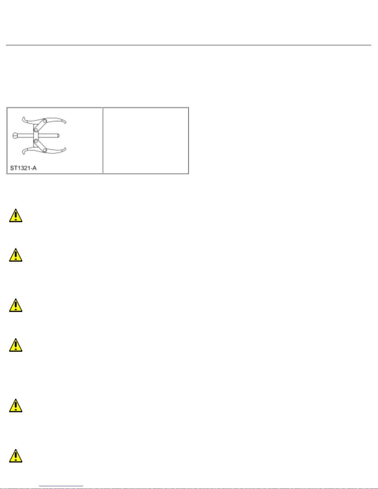
Special Service Tool(s)
2-Jaw Puller
T77F-4220-B1
Removal
WARNING: ALWAYS WEAR SAFETY GLASSES WHEN REPAIRING AN AIR BAG
VEHICLE AND WHEN HANDLING AN AIR BAG.
WARNING: CARRY A LIVE AIR BAG WITH THE BAG AND TRIM COVER
POINTED AWAY FROM YOUR BODY. AN ACCIDENTAL DEPLOYMENT WILL THEN
DEPLOY WITH A MINIMAL CHANCE OF INJURY.
WARNING: PLACE A LIVE AIR BAG ON A BENCH OR OTHER SURFACE WITH
THE TRIM COVER UP.
WARNING: AFTER DEPLOYMENT, THE AIR BAG SURFACE MAY CONTAIN
DEPOSITS OF SODIUM HYDROXIDE, A PRODUCT OF THE GAS GENERANT
COMBUSTION THAT IS IRRITATING TO THE SKIN. WASH YOUR HANDS WITH SOAP
AND WATER AFTER HANDLING A DEPLOYED AIR BAG.
WARNING: NEVER PROBE THE CONNECTORS ON THE AIR BAGS. DOING SO
MAY RESULT IN AIR BAG DEPLOYMENT WHICH COULD RESULT IN PERSONAL
INJURY.
WARNING: AIR BAG MODULES WITH DISCOLORED OR DAMAGED COVERS OR
http://www.fordtechservice.dealerconnection.com/pubs/content/~WSV1/~MUS~LEN/19/SV1B4002.HTM (1 of 11) [7/10/2007 4:44:52 PM]
Page 2
1997 F-150/250
DEPLOYMENT DOORS MUST BE REPLACED, NOT REPAINTED.
WARNING: VEHICLE SENSOR ORIENTATION IS CRITICAL FOR PROPER
SYSTEM OPERATION. IF A VEHICLE EQUIPPED WITH AN AIR BAG SYSTEM IS
INVOLVED IN A COLLISION, INSPECT THE SENSOR MOUNTING BRACKET AND
WIRING PIGTAIL FOR DEFORMATION. IF DAMAGED, THE SENSOR SHOULD BE
REPLACED WHETHER OR NOT THE AIR BAG IS DEPLOYED.
1.
WARNING: TO AVOID ACCIDENTAL DEPLOYMENT AND POSSIBLE
INJURY, THE BACKUP POWER SUPPLY MUST BE DEPLETED BEFORE
SERVICING OR REPLACING ANY AIR BAG SYSTEM COMPONENTS. TO
DEPLETE THE BACKUP POWER SUPPLY ENERGY, DISCONNECT THE BATTERY
TO STARTER RELAY CABLE AND WAIT ONE MINUTE.
NOTE: Make sure the front wheels (1007) are in the straight-ahead position.
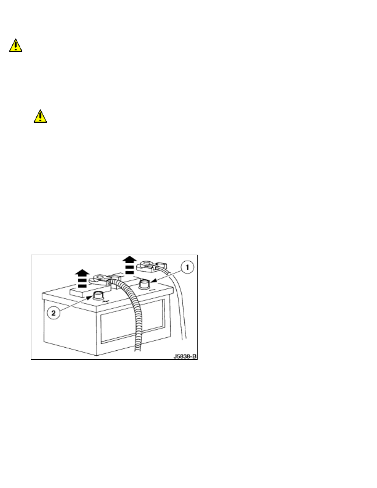
Remove the battery cables.
1. Remove the battery ground cable (14301).
2. Remove the battery to starter relay cable (14300) and wait one minute for the
backup power supply to be depleted.
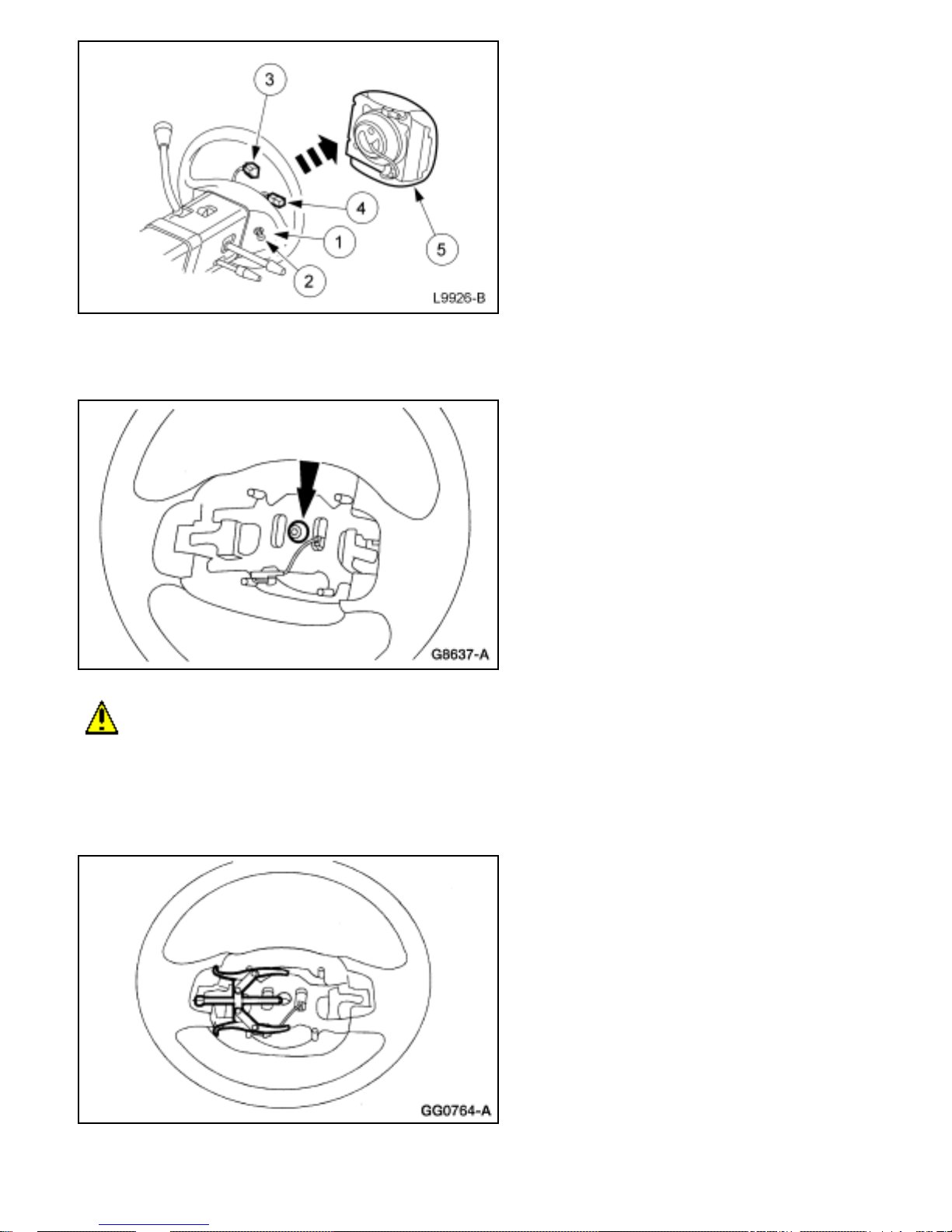
2. Remove the driver side air bag module (043B13).
1. Remove the two back cover plugs.
2. Remove the screws.
3. Disconnect the horn electrical connector.
4. Disconnect the air bag sliding contact electrical connector.
5. Remove the driver side air bag module.
http://www.fordtechservice.dealerconnection.com/pubs/content/~WSV1/~MUS~LEN/19/SV1B4002.HTM (2 of 11) [7/10/2007 4:44:52 PM]
Page 3
1997 F-150/250
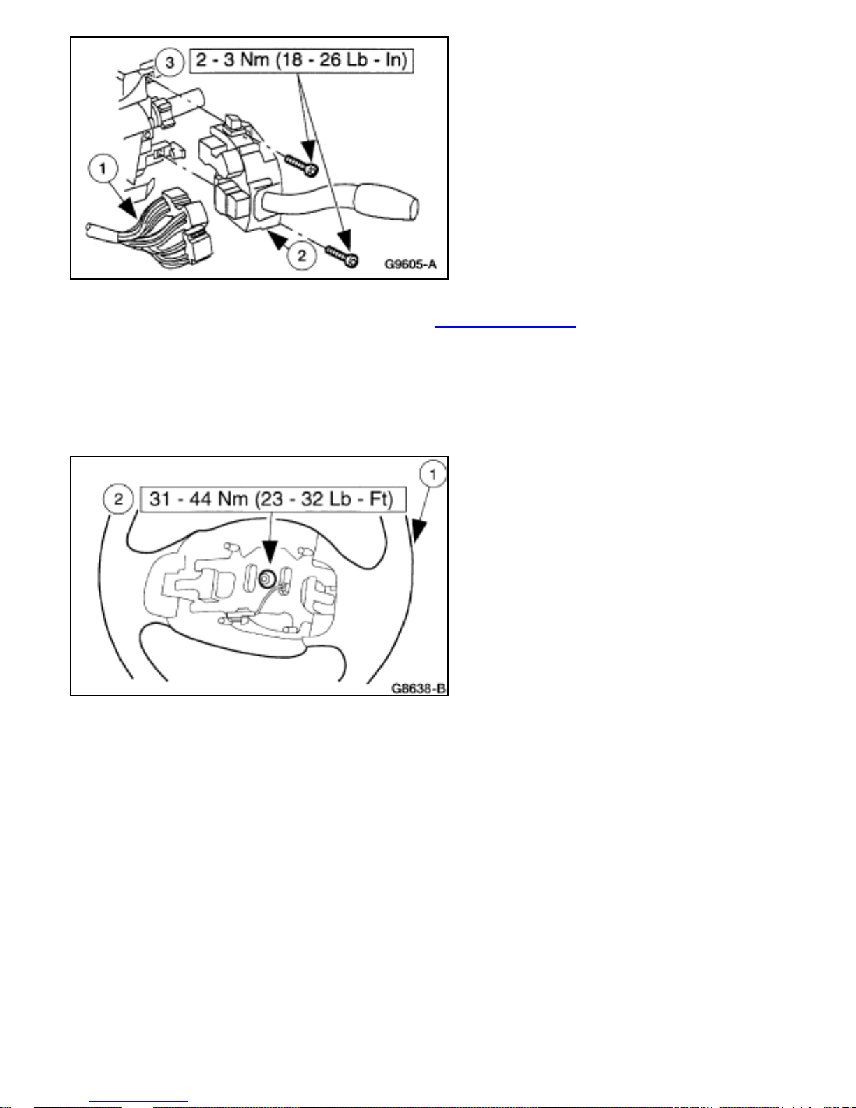
3. Remove the steering wheel bolt.
4. CAUTION: Removing the steering wheel without using a puller can
damage the column bearings.
Use 2-Jaw Puller to remove the steering wheel (3600).
http://www.fordtechservice.dealerconnection.com/pubs/content/~WSV1/~MUS~LEN/19/SV1B4002.HTM (3 of 11) [7/10/2007 4:44:52 PM]
Page 4
1997 F-150/250
5. Remove the air bag sliding contact (14A664); refer to Section 501-20B .
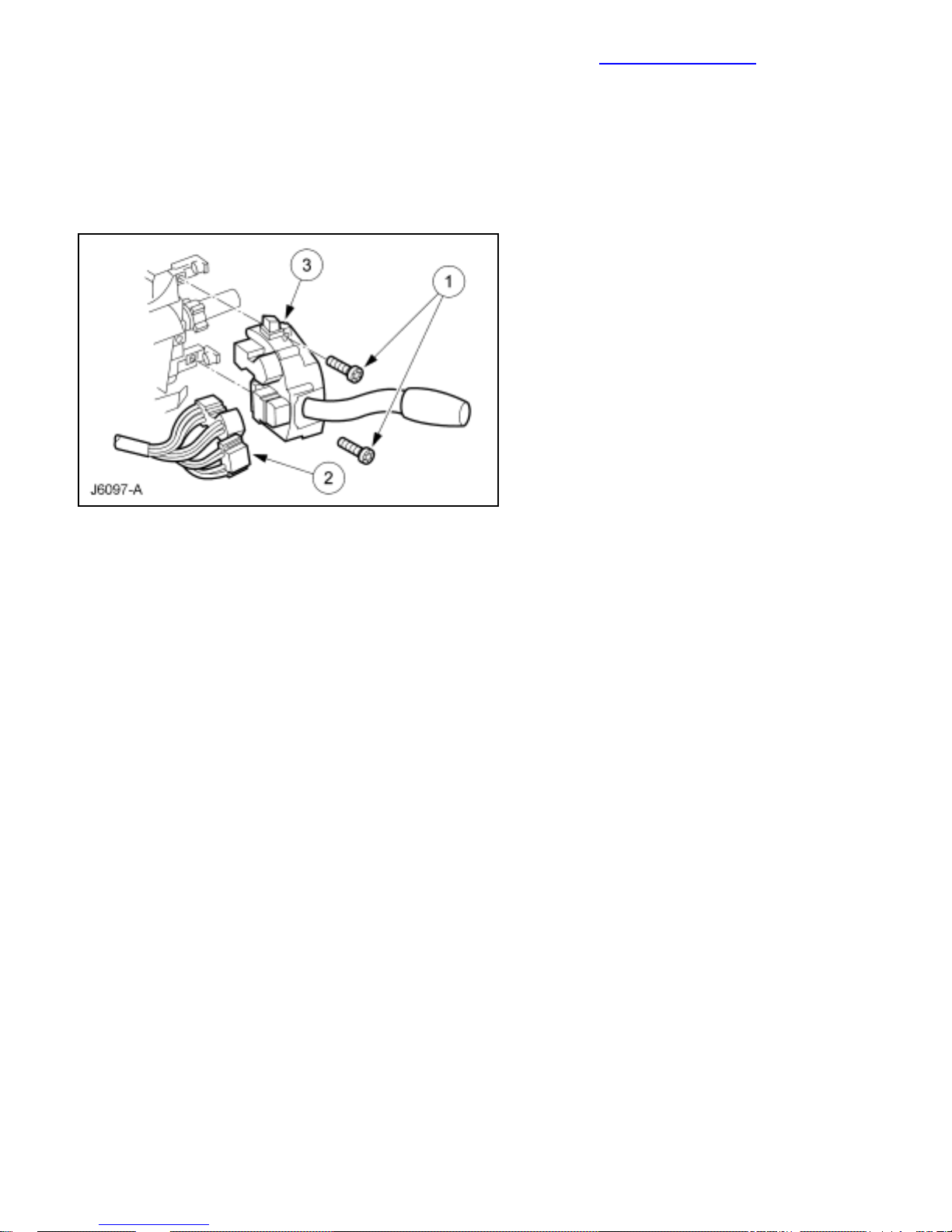
6. Remove the multi-function switch (13K359).
1. Remove the screws.
2. Disconnect the electrical connector.
3. Remove the multi-function switch.
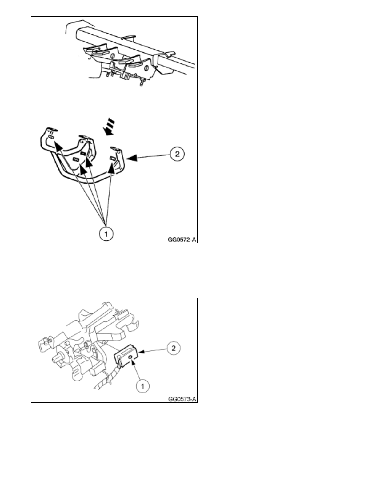
7. Remove the instrument panel steering column opening cover reinforcement.
1. Remove the nuts.
2. Remove the instrument panel steering column opening cover reinforcement.
http://www.fordtechservice.dealerconnection.com/pubs/content/~WSV1/~MUS~LEN/19/SV1B4002.HTM (4 of 11) [7/10/2007 4:44:52 PM]
Page 5
1997 F-150/250
8. Disconnect the ignition switch electrical connector.
1. Remove the bolt.
2. Disconnect the electrical connector.
9. On automatic transmission vehicles, remove the transmission range indicator from the
steering column.
http://www.fordtechservice.dealerconnection.com/pubs/content/~WSV1/~MUS~LEN/19/SV1B4002.HTM (5 of 11) [7/10/2007 4:44:52 PM]
Page 6
1997 F-150/250
10. Remove the steering column shaft bolt.
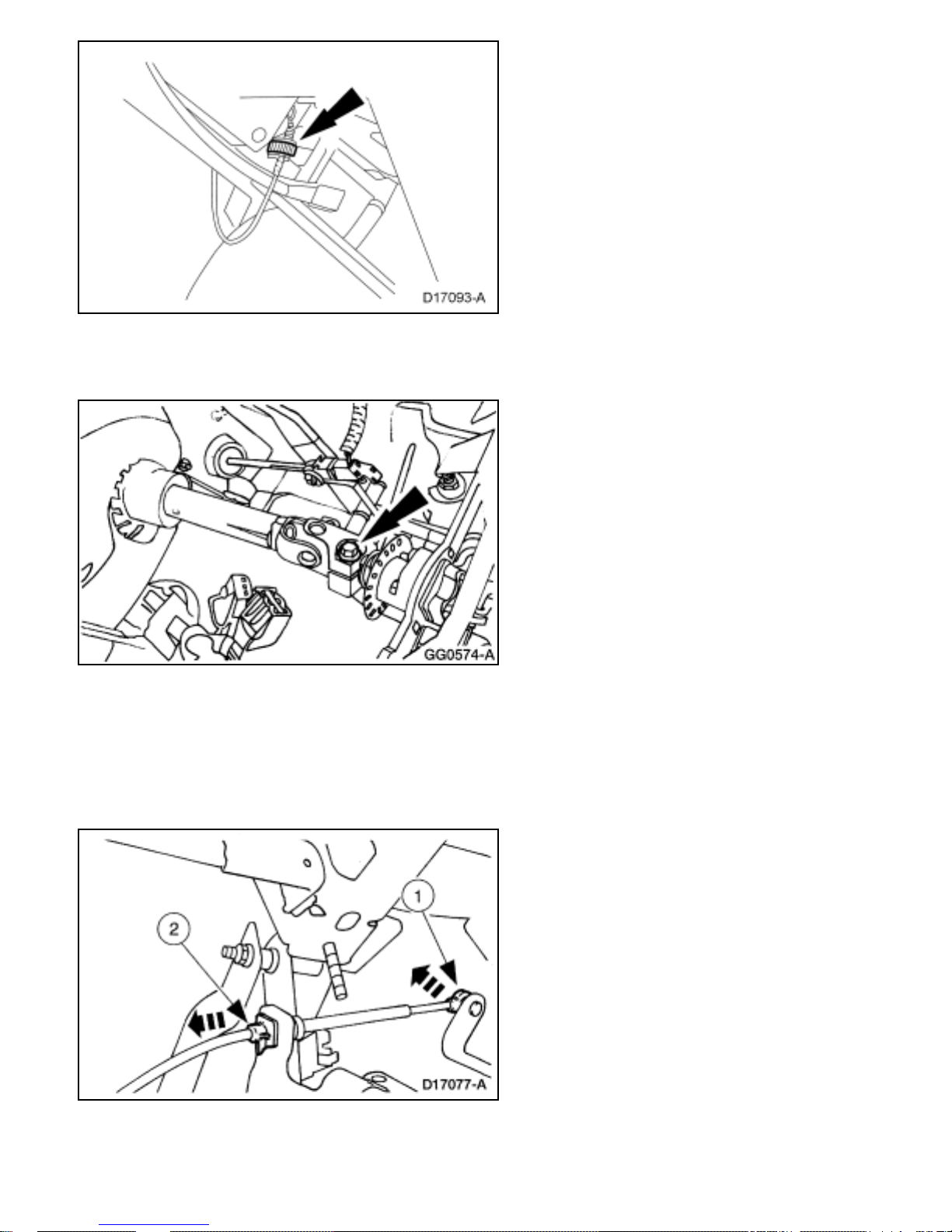
11. On automatic transmission vehicles, disconnect the shift cable from the steering
column.
1. Disconnect the shift cable from the steering column shift tube lever.
2. Disconnect the shift cable from the steering column bracket.
12. Remove the steering column.
http://www.fordtechservice.dealerconnection.com/pubs/content/~WSV1/~MUS~LEN/19/SV1B4002.HTM (6 of 11) [7/10/2007 4:44:52 PM]
Page 7
1997 F-150/250
1. Remove the nuts.
2. Remove the steering column.
Installation
1. Position the steering column and install the nuts.
2. Install the steering column shaft bolt.
http://www.fordtechservice.dealerconnection.com/pubs/content/~WSV1/~MUS~LEN/19/SV1B4002.HTM (7 of 11) [7/10/2007 4:44:52 PM]
Page 8

1997 F-150/250
3. On automatic transmission vehicles, connect the shift cable to the steering column.
1. Connect the shift cable to the steering column instrument panel bracket (3676).
2. Connect the shift cable to the shift tube lever.
4. On automatic transmission vehicles, install the transmission range indicator.
5. Connect the ignition switch electrical connector.
http://www.fordtechservice.dealerconnection.com/pubs/content/~WSV1/~MUS~LEN/19/SV1B4002.HTM (8 of 11) [7/10/2007 4:44:52 PM]
Page 9
1997 F-150/250
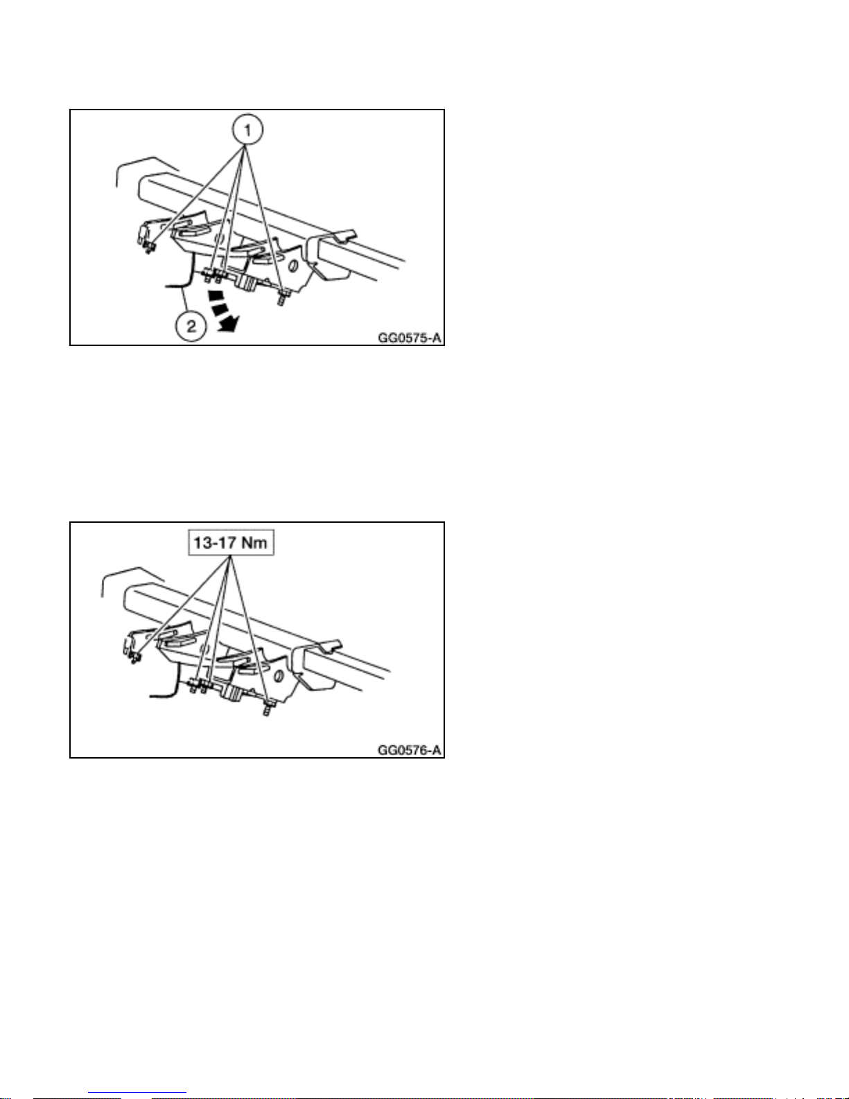
6. Position the instrument panel steering column opening cover reinforcement and install
the nuts.
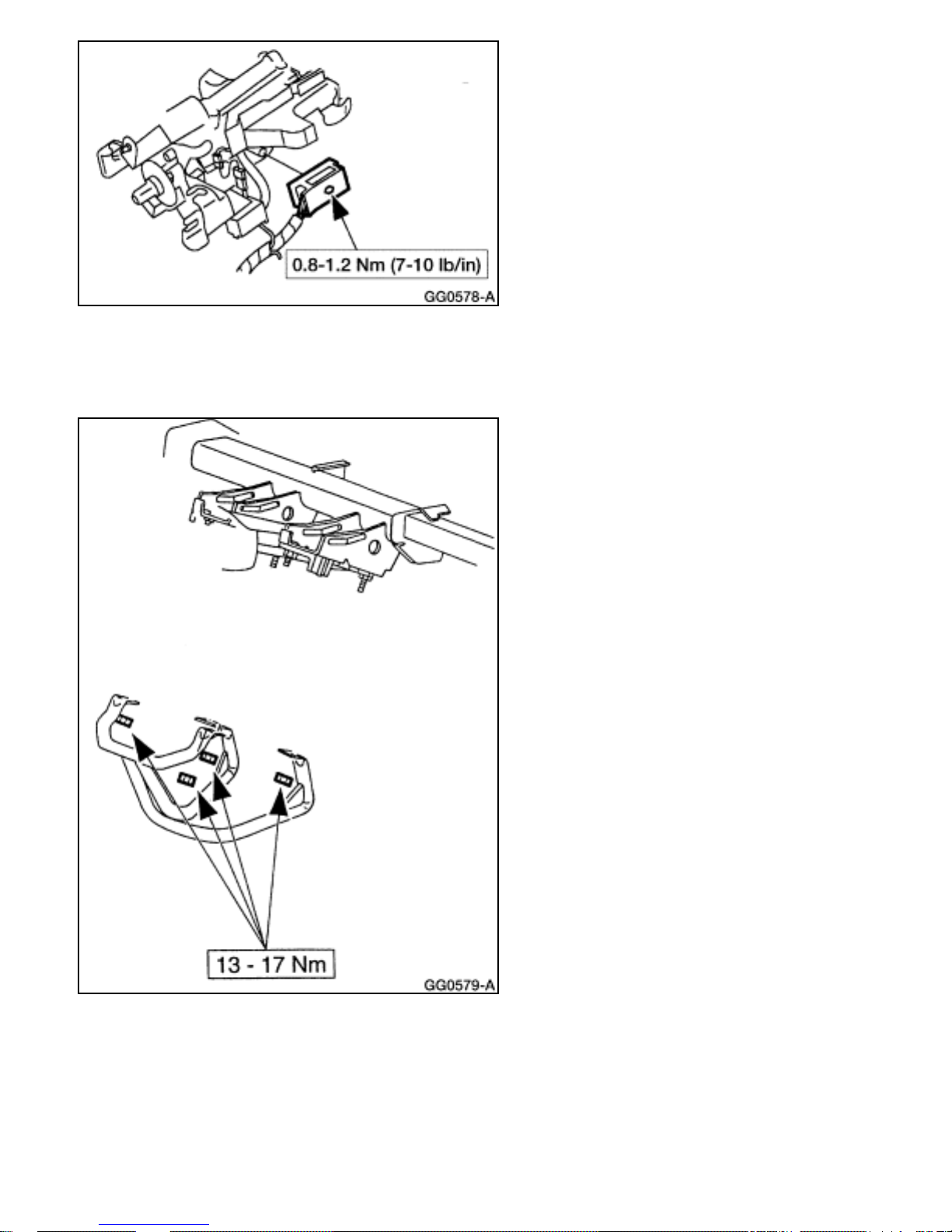
7. Install the multi-function switch.
1. Connect the electrical connector.
2. Position the multi-function switch.
3. Install the screws.
http://www.fordtechservice.dealerconnection.com/pubs/content/~WSV1/~MUS~LEN/19/SV1B4002.HTM (9 of 11) [7/10/2007 4:44:52 PM]
Page 10
1997 F-150/250
8. Install the air bag sliding contact; refer to Section 501-20B .
9. Install the steering wheel.
1. Position the steering wheel.
2. Install the bolt.
10. Install the driver side air bag module.
1. Connect the air bag sliding contact electrical connector.
2. Connect the horn electrical connector.
3. Position the driver side air bag module.
4. Install the two screws.
http://www.fordtechservice.dealerconnection.com/pubs/content/~WSV1/~MUS~LEN/19/SV1B4002.HTM (10 of 11) [7/10/2007 4:44:52 PM]
Page 11

1997 F-150/250
NOTE: When the battery (10655) is disconnected and reconnected, some abnormal drive
symptoms may occur while the vehicle relearns its adaptive strategy. The vehicle may need to
be driven 16 km (10 mi) to relearn the strategy.
11. Connect the battery cables.
1. Connect the battery to starter relay cable.
2. Connect the battery ground cable.
http://www.fordtechservice.dealerconnection.com/pubs/content/~WSV1/~MUS~LEN/19/SV1B4002.HTM (11 of 11) [7/10/2007 4:44:52 PM]
Page 12

1997 F-150/250
Automatic Transmission
Disassembly
1. Remove the
Steering Column; refer to the procedure in this section.
2. Remove the bearing retainer.
3. Remove the steering column lock housing bearing (3E700).
4. Remove the steering column lock gear (3E717).
http://www.fordtechservice.dealerconnection.com/pubs/content/~WSV1/~MUS~LEN/19/SV1B4007.HTM (1 of 20) [7/10/2007 4:46:03 PM]
Page 13

1997 F-150/250
5. On fixed steering columns, remove the bearing retainer from the bottom of the steering
column shaft.
6. On tilt steering columns, remove the sensor ring.
1. Remove the steering column bearing spring.
2. Remove the sensor ring.
7. Remove the steering column bearing tolerance ring from the steering column shaft.
http://www.fordtechservice.dealerconnection.com/pubs/content/~WSV1/~MUS~LEN/19/SV1B4007.HTM (2 of 20) [7/10/2007 4:46:03 PM]
Page 14

1997 F-150/250
8. Remove the lock cylinder housing screws.
9. WARNING: THE STEERING COLUMN POSITION SPRING IS UNDER TENSION
AND MAY COME OUT WITH GREAT FORCE.
Remove the steering column lock cylinder housing and the steering column shaft from the
steering actuator housing.
1. Pry up on the steering column locking levers using shop fabricated tool; refer to
General Procedures in this section.
2. On tilt steering columns, remove the steering column position spring.
http://www.fordtechservice.dealerconnection.com/pubs/content/~WSV1/~MUS~LEN/19/SV1B4007.HTM (3 of 20) [7/10/2007 4:46:03 PM]
Page 15

1997 F-150/250
10. Remove the bearing retainer.
11. Remove the steering column bearing spring.
12. Remove the steering column bearing sleeve.
13. Remove the steering column bearing tolerance ring.
1. Slide the steering column shaft in toward the steering column lock cylinder housing,
then out.
http://www.fordtechservice.dealerconnection.com/pubs/content/~WSV1/~MUS~LEN/19/SV1B4007.HTM (4 of 20) [7/10/2007 4:46:03 PM]
Page 16

1997 F-150/250
2. Slide the steering column bearing tolerance ring off the steering column shaft.
14. Remove the steering column bearing from the steering column lock cylinder housing.
15. On tilt columns, remove the steering column bearing from the steering column lock cylinder
housing.
16. Remove the brake shift interlock solenoid.
1. Remove the three bolts.
2. Remove the brake shift interlock solenoid.
http://www.fordtechservice.dealerconnection.com/pubs/content/~WSV1/~MUS~LEN/19/SV1B4007.HTM (5 of 20) [7/10/2007 4:46:03 PM]
Page 17

1997 F-150/250
17. Remove the shift tube.
1. Remove the bolts.
2. Remove the shift tube clamps.
3. Remove the shift tube.
18. Remove the transmission selector lever arm and support (7302).
1. Remove the bolts.
2. Remove the transmission selector lever arm and support.
19. Remove the transmission control selector lever plunger spring (7B071).
http://www.fordtechservice.dealerconnection.com/pubs/content/~WSV1/~MUS~LEN/19/SV1B4007.HTM (6 of 20) [7/10/2007 4:46:03 PM]
Page 18

1997 F-150/250
20. Drive out the gearshift lever pin (7W441) from the shift tube.
21. Remove the gearshift lever (7210).
22. Remove the column shift selector lever plunger (7361).
● If bent, replace the column shift selector lever plunger.
http://www.fordtechservice.dealerconnection.com/pubs/content/~WSV1/~MUS~LEN/19/SV1B4007.HTM (7 of 20) [7/10/2007 4:46:03 PM]
Page 19

1997 F-150/250
23. Remove the (A) gearshift lever socket bushings (7335) and the (B) transmission control
selector lever spring clip.
24. Remove the ignition switch.
1. Remove the bolts.
2. Remove the ignition switch.
25. Remove the lower steering column bearing.
http://www.fordtechservice.dealerconnection.com/pubs/content/~WSV1/~MUS~LEN/19/SV1B4007.HTM (8 of 20) [7/10/2007 4:46:03 PM]
Page 20

1997 F-150/250
26. Remove the steering column lower bearing retainer.
1. Remove the three bolts.
2. Remove the steering column lower bearing retainer.
27. Remove the steering column lock pawl (3E691).
1. Drive out the steering column lock lever pin (3B663).
2. Remove the steering column lock pawl.
28. Remove the (A) upper steering column lock lever actuator and the (B) lower steering column
lock lever actuator.
http://www.fordtechservice.dealerconnection.com/pubs/content/~WSV1/~MUS~LEN/19/SV1B4007.HTM (9 of 20) [7/10/2007 4:46:03 PM]
Page 21

1997 F-150/250
Assembly
1. Install the lower steering column lock actuator to the upper steering column lock lever
actuator.
1. Lubricate the steering column lock actuator.
● Use Steering Gear Grease C3AZ-19578-A or equivalent meeting Ford specification ESW-
M1C87-A.
3. Install the steering column lock actuator.
2. Install the steering column lock pawl.
1. Position the steering column lock pawl.
2. Drive in the steering column lock lever pin.
http://www.fordtechservice.dealerconnection.com/pubs/content/~WSV1/~MUS~LEN/19/SV1B4007.HTM (10 of 20) [7/10/2007 4:46:03 PM]
Page 22

1997 F-150/250
3. Install the steering column lower bearing retainer.
1. Position the steering column lower bearing retainer.
2. Install the three bolts.
4. Install the steering column bearing.
● Install the steering column bearing so that the inner race is visible when installed.
5. Install the ignition switch.
1. Align the ignition switch with the slot and index mark on the steering column.
2. Install the screws.
http://www.fordtechservice.dealerconnection.com/pubs/content/~WSV1/~MUS~LEN/19/SV1B4007.HTM (11 of 20) [7/10/2007 4:46:03 PM]
Page 23

1997 F-150/250
6. Install the (A) transmission control selector lever spring clip and the (B) gearshift lever
socket bushings on the shift tube.
● Coat the gearshift lever socket bushings with Steering Gear Grease C3AZ-19578-A or
equivalent meeting Ford specification ESW-M1C87-A.
7. Install the column shift selector lever plunger.
● Coat the column shift selector plunger with Steering Gear Grease C3AZ-19578-A or
equivalent meeting Ford specification ESW-M1C87-A.
8. Position the gearshift lever in the shift tube.
http://www.fordtechservice.dealerconnection.com/pubs/content/~WSV1/~MUS~LEN/19/SV1B4007.HTM (12 of 20) [7/10/2007 4:46:03 PM]
Page 24

1997 F-150/250
9. Install the gearshift lever pin in the shift tube.
10. Install the gearshift selector tube spring (7379) in the shift tube.
● Coat the end of the spring with Steering Gear Grease C3AZ-19578-A or equivalent
meeting Ford specification ESW-M1C87-A.
11. Install the transmission selector lever arm and support on the shift tube.
1. Position the transmission selector lever arm and support.
2. Install the bolts.
http://www.fordtechservice.dealerconnection.com/pubs/content/~WSV1/~MUS~LEN/19/SV1B4007.HTM (13 of 20) [7/10/2007 4:46:03 PM]
Page 25

1997 F-150/250
12. Install the shift tube.
1. Position the shift tube.
2. Position the shift tube clamps.
3. Install the bolts.
13. Install the brake shift interlock solenoid.
● Position the brake shift interlock solenoid.
● Install the bolts.
14. Install the upper steering column bearing on the steering column lock cylinder housing.
● Use an appropriate bearing installer or socket.
http://www.fordtechservice.dealerconnection.com/pubs/content/~WSV1/~MUS~LEN/19/SV1B4007.HTM (14 of 20) [7/10/2007 4:46:03 PM]
Page 26

1997 F-150/250
● Install the upper steering column bearing so that the inner race is visible when
installed.
15. On tilt steering columns, install the large steering column bearing into the steering column
lock cylinder housing.
● Use an appropriate bearing installer or socket.
● Install the lower steering column bearing so that the inner race is visible when
installed.
16. Install the (A) steering column bearing tolerance ring on the (B) steering column shaft and
position the steering column shaft in the steering column lock cylinder housing.
http://www.fordtechservice.dealerconnection.com/pubs/content/~WSV1/~MUS~LEN/19/SV1B4007.HTM (15 of 20) [7/10/2007 4:46:03 PM]
Page 27

1997 F-150/250
17. Install the steering column bearing sleeve.
18. Install the steering column bearing spring.
19. Install the bearing retainer.
http://www.fordtechservice.dealerconnection.com/pubs/content/~WSV1/~MUS~LEN/19/SV1B4007.HTM (16 of 20) [7/10/2007 4:46:03 PM]
Page 28

1997 F-150/250
20. Install the (A) lock cylinder housing screws loosely and position the (B) steering actuator
housing in a vise.
● Lubricate the lock cylinder housing screws with Rust Penetrant and Inhibitor F2AZ-
19A501-A or equivalent meeting Ford specification ESR-M99C56-A.
21. Position the (A) steering column lock cylinder housing and the (B) steering column shaft on
the (D) steering actuator housing.
● Make sure the upper and lower (C) steering column lock actuators are aligned.
http://www.fordtechservice.dealerconnection.com/pubs/content/~WSV1/~MUS~LEN/19/SV1B4007.HTM (17 of 20) [7/10/2007 4:46:03 PM]
Page 29

1997 F-150/250
22. Position the steering column locking levers on the steering actuator housing.
1. Use shop fabricated tool; refer to General Procedures in this section.
2. On tilt steering columns, install and compress the steering column position spring.
23. Tighten the lock cylinder housing screws.
http://www.fordtechservice.dealerconnection.com/pubs/content/~WSV1/~MUS~LEN/19/SV1B4007.HTM (18 of 20) [7/10/2007 4:46:03 PM]
Page 30

1997 F-150/250
24. Install the steering column bearing tolerance ring.
25. On tilt steering column, install the sensor ring.
1. Install the sensor ring.
2. Install the steering column bearing spring.
26. On fixed steering column, install the bearing retainer.
27. Install the steering column lock gear.
● Use Rust Penetrant and Inhibitor F2AZ-19A501-A or equivalent meeting Ford
http://www.fordtechservice.dealerconnection.com/pubs/content/~WSV1/~MUS~LEN/19/SV1B4007.HTM (19 of 20) [7/10/2007 4:46:03 PM]
Page 31

1997 F-150/250
specification ESR-M99C56-A to coat the steering column lock gear.
28. Lubricate and install the steering column lock housing bearing and rotate clockwise.
● Use Rust Penetrant and Inhibitor F2AZ-19A501-A or equivalent meeting Ford
specification ESR-M99C56-A.
29. Install the steering column upper bearing retainer.
http://www.fordtechservice.dealerconnection.com/pubs/content/~WSV1/~MUS~LEN/19/SV1B4007.HTM (20 of 20) [7/10/2007 4:46:03 PM]
 Loading...