

Ford 1997 Aerostar, 1997 Ranger Workshop Manual

Clean the valve covers and mating surfaces.
Section 03-01B: Engine, 3.0L V-6 1997 Aerostar, Ranger Workshop Manual
Page
1
of 41997 Aerostar/Ranger
2011
-04-27file://C:\TSO\tsocache\VDTOM_5368\SVK~us~en~file=SVK31B14.HTM~gen~ref.HTM
tomsn048@gmail.com
IN-VEHICLE SERVICE
Valve Cover and Gasket
NOTE: The rocker covers installed on the 3.0L engine incorporate integral (built-in) gaskets which
should last the life of the vehicle. Be sure to adhere to the following steps when removing and
replacing rocker covers. Replacement gaskets are available if required.
Removal
1. Disconnect battery ground cable (14301) and set aside.
2. Disconnect the crankcase ventilation hose from the air cleaner outlet tube. Disconnect the wiring
connectors from the mass air flow (MAF) sensor, intake air temperature (IAT) sensor, and the
harness locator from the outlet tube. Loosen the clamps at the throttle body and air cleaner and
remove the outlet tube.
3. Remove air cleaner outlet tube.
4. Disconnect the canister purge hose from the canister purge valve at the LH frame rail and the locator
from the accelerator control bracket. Remove the accelerator control splash shield.
5. Disconnect the throttle cable (09A758A) and speed control cable (9A825) from the throttle body and
the locator at the top of the intake manifold. Remove the cable bracket retaining bolts and remove
bracket with cables attached. Position the bracket and cables out of the way.
6. Disconnect the wiring connectors from the coil connector, radio noise suppressor, the EVR and left
side spark plug wires from coil. Disconnect right side spark plug wires from the locators and wires
from the spark plugs. Disconnect the vacuum hose from the EVR and heater control tee. Remove the
brace from the coil bracket and the exhaust manifold. Remove the coil assembly.
7. Disconnect the right side valve cover harness locators. Disconnect the IAT harness locator from the
generator bracket. Remove the right side valve cover and gasket.
8. Disconnect the DPFE vacuum hoses and the wiring connector. Remove the EGR valve tube from the
valve and exhaust manifold.
9. Disconnect the vacuum hoses from the brake booster, EGR, and the engine vacuum harness from
upper intake and position the harness out of the way.
10. Disconnec the wiring connectors from the throttle position sensor (TPS) and idle air control (IAC).
Disconnect the 42-pin connector from the bracket at the rear of intake manifold. Remove the positive
crankcase ventilation (PCV) valve from the valve cover.
11. Remove the upper intake manifold and gasket. Tape the lower intake openings closed.
12. Disconnect the left side spark plug wire locators and wires from the spark plugs. Remove the left side
valve cover and gasket.
13. NOTE: Do not clean the valve cover gasket with solvent. Damage to the valve cover gasket
may occur.

14. Clean upper intake manifold and mating surfaces.
symptoms may occur while the powertrain control module (PCM) (12A650) relearns its
Page
2
of 41997 Aerostar/Ranger
2011
-04-27file://C:\TSO\tsocache\VDTOM_5368\SVK~us~en~file=SVK31B14.HTM~gen~ref.HTM
tomsn048@gmail.com
Installation
1. NOTE: Use Silicone Gasket and Sealant F6AZ-19562-AA or equivalent meeting Ford
specification WSE-M4G323-A6.
Apply sealant and install the left valve cover and a new gasket. Tighten the bolts to 14 Nm (10 lb-ft).
2. NOTE: Use Silicone Gasket and Sealant F6AZ-19562-AA or equivalent meeting Ford
specification WSE-M4G323-A6.
Apply sealant and install the right valve cover and a new gasket. Tighten the bolts to 14 Nm (10 lb-ft).
3. Route the left side spark plug wires and connect the wires to the locators on the valve cover and to
the spark plugs.
4. NOTE: Tighten the bolts in sequence in two steps.
Remove the tape from the lower intake manifold and install a new gasket. Install upper intake
manifold, and the three bolts and the three stud bolts. Tighten the bolts in two steps. Tighten to 20
Nm (14 (lb-ft) then tighten to 25 Nm (18 lb-ft). Route and connect the PCV valve and hose.
5. Connect the brake booster vacuum, EGR valve and the engine vacuum harness to the upper intake
manifold.
6. Install the coil and bracket assembly to the upper intake manifold. Install the coil bracket brace to the
bracket and exhaust manifold. Tighten the retainers to 18 Nm (13 lb-ft).
7. Connect the wiring connectors to the coil connector, radio noise suppressor, EVR vacuum and
electrical connectors, left side spark plug wires to the coil and right side spark plug wires to the spark
plugs.
8. Connect the right side valve cover harness locators. Connect the heater control vacuum hose source
to the engine vacuum harness. Connect the IAT harness locator to the generator bracket.
9. Install the EGR valve tube. Tighten the tube nut to 20 Nm (15 lb-ft). Tighten the bolt to 16 Nm (11 lbft). Connect the DPFE vacuum hoses and electrical connector.
10. Connect the throttle cable (09A758A) and speed control cable (9A825) to the throttle body and
locator. Install the bracket with cables attached to the throttle body. Tighten the bolts to 10 Nm (89 lbin).
11. Connect the canister purge hose to the valve and the locator to the accelerator control bracket. Install
the accelerator control splash shield.
12. Connect the wiring connectors to the TPS and IAC and the 42-pin connector to the bracket at the rear
of the intake manifold.
13. Install the outlet tube and tighten the clamps securely. Connect the crankcase ventilation hose to the
air cleaner outlet tube. Connect the wiring connectors to the MAF sensor, IAT sensor, and the
harness locator to the outlet tube.
14. NOTE: When the battery has been disconnected and reconnected, some abnormal drive
adaptive strategy. The vehicle may need to be driven 16 km (10 miles) or more to relearn the
Item
Page
3
of 41997 Aerostar/Ranger
2011
-04-27file://C:\TSO\tsocache\VDTOM_5368\SVK~us~en~file=SVK31B14.HTM~gen~ref.HTM
tomsn048@gmail.com
strategy.
Connect battery ground cable .
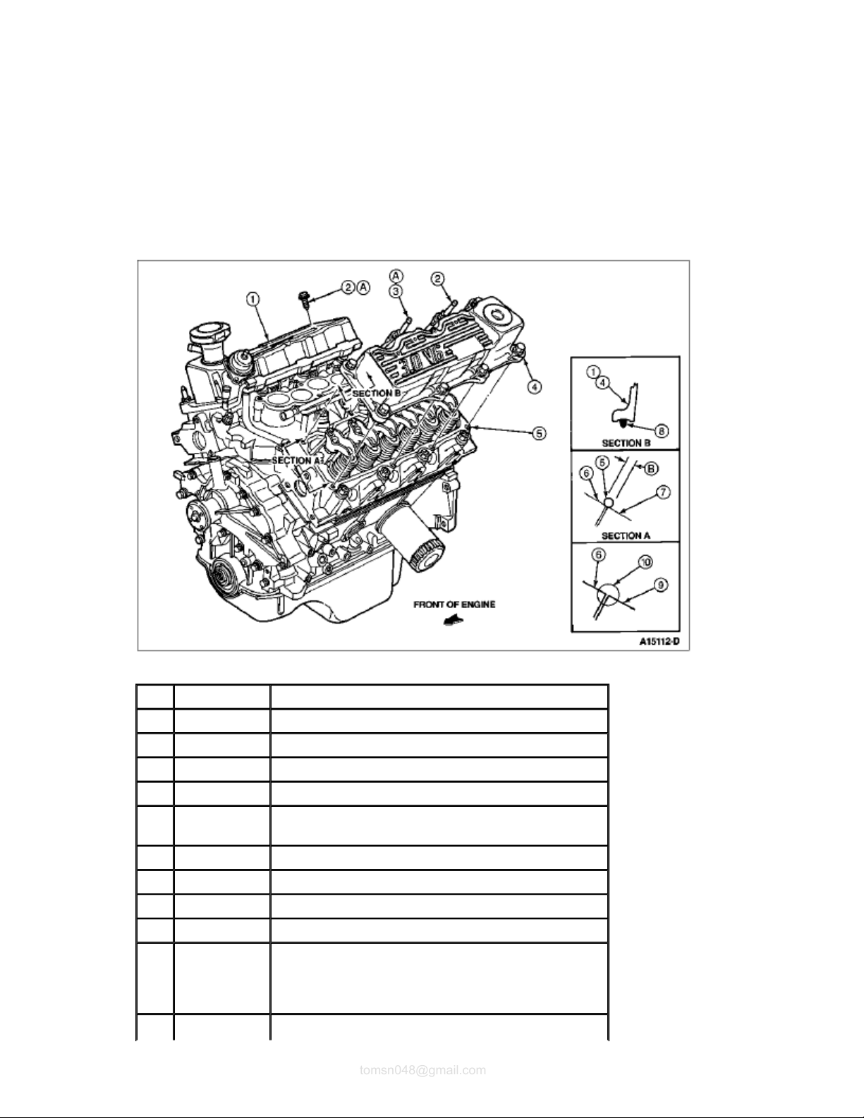
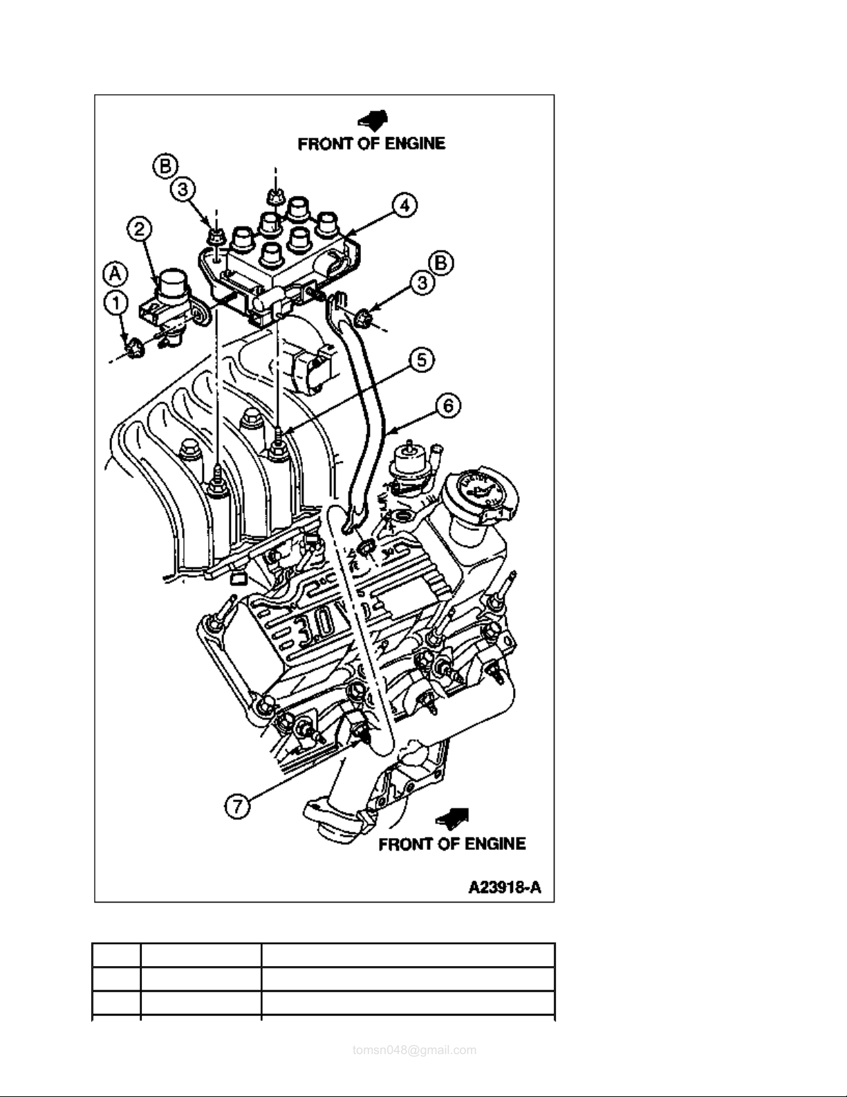
Valve Cover Installation, Ranger
Part Number Description
1 6582 Valve Cover (RH)
2 N803298-S Screw and Washer
3 N803262-S Stud
4 6582 Valve Cover (LH)
5 ESE-
M4G195-B
6 9424 Intake Manifold
7 6049 Cylinder Head
8 6584 Valve Cover Gasket
9 6049 Cylinder Head
10 — Intersection of Head and Intake Manifold Must Be
A — Tighten to 10-14 Nm
Sealer
Flush to Within ± 1mm
(0.04 In.). Gasket Must Not Protrude Above Highest
Surface.

Page
4
of 41997 Aerostar/Ranger
2011
-04-27file://C:\TSO\tsocache\VDTOM_5368\SVK~us~en~file=SVK31B14.HTM~gen~ref.HTM
tomsn048@gmail.com
(7-10 Lb-Ft)
B — 4-6mm (.15-.23 In.)

Section 03-01B: Engine, 3.0L V-6 1997 Aerostar, Ranger Workshop Manual
Page
1
of 11997 Aerostar/Ranger
2011
-04-27file://C:\TSO\tsocache\VDTOM_5368\SVK~us~en~file=SVK31B15.HTM~gen~ref.HTM
tomsn048@gmail.com
IN-VEHICLE SERVICE
Rocker Arm
Refer to Valve Tappet, Hydraulic In-Vehicle Service for removal and installation of the rocker arms. Perform
only the steps necessary to remove the rocker arms.
Section 03-01B: Engine, 3.0L V-6 1997 Aerostar, Ranger Workshop Manual
Page
1
of 61997 Aerostar/Ranger
2011
-04-27file://C:\TSO\tsocache\VDTOM_5368\SVK~us~en~file=SVK31B16.HTM~gen~ref.HTM
tomsn048@gmail.com
IN-VEHICLE SERVICE
Valve Tappet, Hydraulic
NOTE: Before replacing a tappet for noisy operation,
make sure the noise is not caused by improper
valve-to-rocker arm clearance or by worn rocker arms or push rods. Refer to Section 03-00 .
Removal
1. NOTE: On 3.0L Aerostar it is necessary to remove the engine (6007) from the vehicle to
perform this procedure. Refer to Engine Assembly, Aerostar , Removal and Installation, in this
section.
Disconnect ground cable at battery and set aside.
2. Drain engine cooling system.
3. Remove PCV closure hose from valve cover (6582) and air cleaner outlet tube.
4. Remove air cleaner outlet tube from throttle body (9E926) and engine air cleaner (ACL) (9600).
5. WARNING: COVER THE VALVE WITH A SHOP RAG TO PREVENT ACCIDENTAL FUEL
SPRAY INTO THE EYES.
Carefully relieve fuel pressure at fuel supply manifold fuel pressure relief valve as outlined in Section
03-04B .
6. Remove fuel tube clips. Disconnect fuel lines as outlined in Section 03-04B .
7. Mark location of vacuum lines and remove.
8. Disconnect electrical connectors of:
Intake air temperature sensor (IAT sensor) (12A697)
Idle air control valve (IAC valve) (9F715)
Engine coolant temperature sensor (ECT sensor) (12A648)
Camshaft position sensor (12A112)
Ignition coil
Radio ignition interference capacitor (18801)
Water temperature indicator sender unit (10884)
EGR pressure sensor, if equipped
EGR vacuum regulator control, if equipped
9. Disconnect upper radiator hose from thermostat housing. After loosening hose clamp, use a twisting
motion on hose to loosen from housing.

10. Remove ignition coil and bracket assembly (two nuts) from top of throttle body and pencil brace at
rag in the tappet valley to catch any gasket material. After scraping, carefully lift cloth from tappet
Page
2
of 61997 Aerostar/Ranger
2011
-04-27file://C:\TSO\tsocache\VDTOM_5368\SVK~us~en~file=SVK31B16.HTM~gen~ref.HTM
tomsn048@gmail.com
exhaust manifold.
11. Remove throttle body, refer to Section 03-04B .
12. Disconnect fuel injector harness retaining standoffs from inboard rocker arm cover studs. Carefully
disconnect electrical connections to each fuel injector and remove fuel charging wiring (9D930) from
engine.
13. Disconnect heater water hoses at engine.
14. Remove spark plug wire set (12281) from spark plugs (12405) by using a twisting motion on the
rubber boot. Remove harness retaining standoffs from rocker arm cover studs.
15. Remove valve covers as outlined in this section.
16. NOTE: Intake manifold (9424) may be removed with fuel injection supply manifold (9F792) and
fuel injectors in place.
Remove intake manifold retaining bolts using a Torx® head socket. Before attempting to remove
intake manifold, break the seal between the manifold and cylinder blocks (6010). Wedge a large
screwdriver or similar heavy-duty tool between the intake manifold and the cylinder blocks. Pry
upward on the tool using the lug on top of the engine front cover (6019) as a leverage point. Removal
of generator (GEN) (10300) may be required for this step. Use care to prevent damage to machined
surfaces.
17. Loosen rocker arm bolt of the valve tappet (6500) to be replaced enough to allow the rocker arm
(6564) to be lifted off the push rod (6565) and rotated to one side.
18. Remove push rods. If more than one is removed, identify each push rod's location. The push rods
should be installed in their original location and position during reassembly.
19. Loosen roller tappet guide plate retainer bolts (2). Remove tappet guide plate retainer from tappet
valley.
20. Remove valve tappet guide plate (6K512) from valve tappets by lifting straight up.
21. NOTE: If the valve tappets are stuck in the bore(s) due to excessive varnish or gum deposits, it
may be necessary to use a claw-type tool to aid removal. Work the valve tappet in and out of
the lifter bore to loosen it from the deposits.
To remove, grasp valve tappet and pull in line with bore.
nstallation
I
NOTE: Lightly oil all bolt and stud threads before installation.
1. CAUTION: Aluminum components gouge easily, which may result in gasket leaks.
Always use care when scraping aluminum gasket surfaces.
Clean mating gasket surfaces of intake manifold and cylinder head (6049). Lay a clean cloth or shop
valley preventing any particles to enter oil drain holes or cylinder head. Use a suitable solvent to
Page
3
of 61997 Aerostar/Ranger
2011
-04-27file://C:\TSO\tsocache\VDTOM_5368\SVK~us~en~file=SVK31B16.HTM~gen~ref.HTM
tomsn048@gmail.com
remove old rubber sealant.
2. Lubricate valve tappets and bore with Engine Assembly Lubricant D9AZ-19579-D or equivalent
meeting Ford specification ESR-M99C80-A.
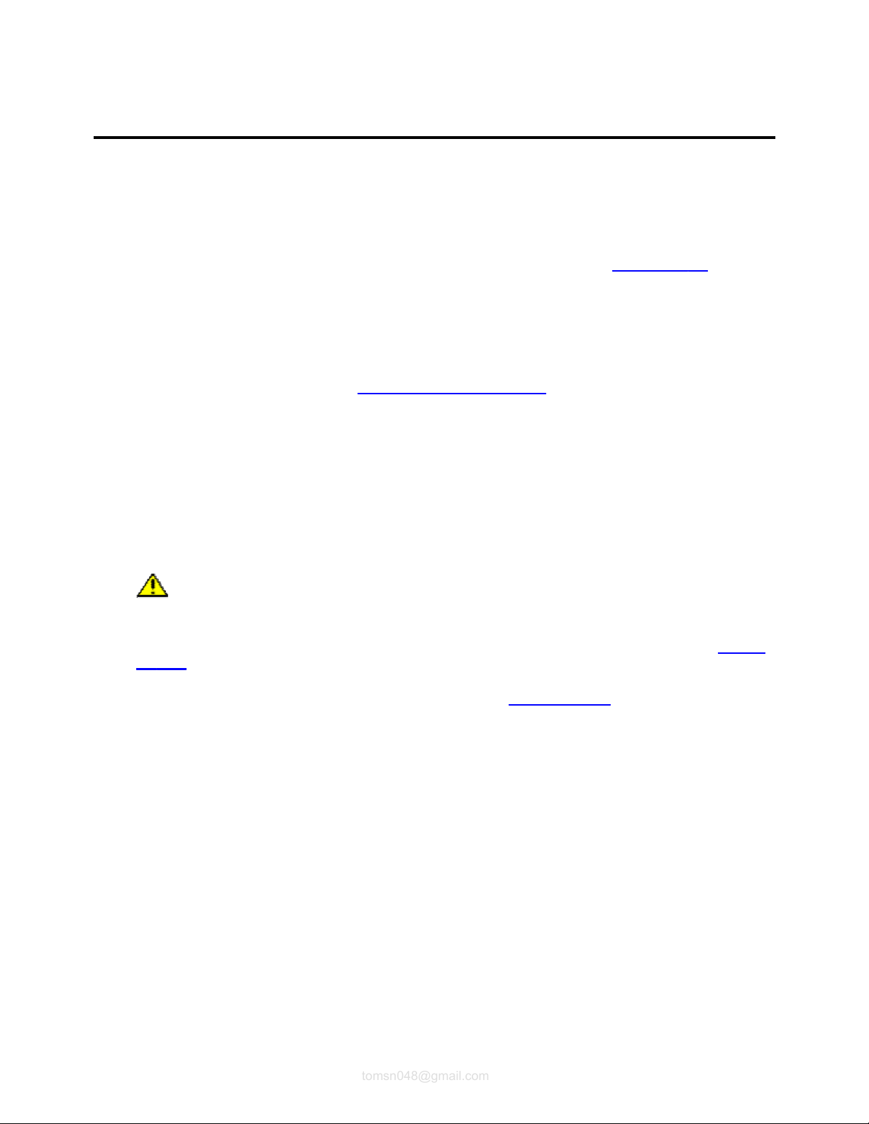
Item Part Number Description
1 — Bolt (Part of 6K564)
2 6K564 Tappet Guide Plate and Retainer
3 — Cylinder Block Assembly Tappet Bore
(Part of 6010)
4 — Washer (Part of 6K564)
5 — Cylinder Block Assembly Guide Plate Retainer
(Part of 6010)
6 6500 Valve Tappet
7 6K512 Valve Tappet Guide Plate
A — Tighten to 10-14 Nm
(7-10 Lb-Ft)
3. Install valve tappet into bore.
in rocker arm and lifter sockets prior to final
-
tightening.
Page
4
of 61997 Aerostar/Ranger
2011
-04-27file://C:\TSO\tsocache\VDTOM_5368\SVK~us~en~file=SVK31B16.HTM~gen~ref.HTM
tomsn048@gmail.com
4. NOTE: Install plate with the word "UP" and button visible.
Align valve tappet flats. Install valve tappet guide plate.
5. Install tappet guide plate retainer over valve tappet guide plates. Retainer orientation is not important.
Hand-start two retaining bolts. Tighten bolts to 10-14 Nm (7-10 lb-ft).
6. Apply a 5-6mm drop of Silicone Rubber D6AZ-19562-AA or -BA or equivalent meeting Ford
specification ESB-M4G92-A or ESE-M4G195-A to intersection of cylinder block and cylinder head
assembly at four corners as shown in the illustration under Intake Manifold in this section.
7. Position intake manifold gaskets (9439) onto cylinder heads. Align the intake gasket locking tabs to
the provisions on the cylinder head gaskets as shown in the illustration.
8. Install front and rear intake manifold seals as shown in the illustration under Intake Manifold in this
section. Secure with retaining features.
9. Lower intake manifold into position aligning manifold bolt holes to those in the cylinder head. Use
care to prevent disturbing the rubber sealer which can cause sealing voids. Install bolts 1, 2, 3 and 4
and hand-snug. Install remaining bolts and tighten in a two-step process. Tighten in numerical
sequence to 15 Nm (11 lb-ft), then again to 26-32 Nm (19-24 lb-ft).
10. NOTE: Rocker arm must be fully seated into cylinder head and push rod must be fully seated

Apply ESE-M2C39-F oil to removed push rods and rocker arms. Install push rods. Move rocker arms
adaptive strategy. The vehicle may need to be driven 16 km (10 miles) or more to relearn the
Page
5
of 61997 Aerostar/Ranger
2011
-04-27file://C:\TSO\tsocache\VDTOM_5368\SVK~us~en~file=SVK31B16.HTM~gen~ref.HTM
tomsn048@gmail.com
into position with push rod and snug rocker arm bolts. Rotate crankshaft (6303) to position camshaft
lobe(s) straight down and away from push rods. Tighten rocker arm bolt to 11 Nm (8 lb-ft) to seat
rocker arm into cylinder head. Final-tighten bolt to 26-38 Nm (19-28 lb-ft).
11. Install valve covers as outlined in this section.
12. Install fuel charging wiring to each fuel injector. Secure with standoffs to inboard rocker arm cover
studs.
13. Install throttle body assembly and new intake manifold upper gasket (9H486) as outlined in Section
03-04B . Install ignition coil and bracket assembly (Ranger only). Tighten retaining nuts to 16-20 Nm
(12-15 lb-ft).
14. Install spark plug wire set and bracket RH and/or spark plug wire set LH. Install wire harness
standoffs to rocker arm cover studs and connect wires to spark plugs and ignition coil.
15. Install fuel lines to fuel injection supply manifold as outlined in Section 03-04B .
16. Install fuel tube clips.
17. Install upper radiator hose and heater water hoses. Tighten hose clamps securely.
18. Connect vacuum lines to premarked locations.
19. Connect electrical connections of:
Intake air temperature sensor
Idle air control valve (IAC valve)
Engine coolant temperature sensor
Distributor
Ignition coil
Radio ignition interference capacitor
Water temperature indicator sender unit
EGR pressure sensor, if equipped
EGR vacuum regulator control, if equipped
Refer to Section 18-01 for further information.
20. NOTE: Engine coolant is corrosive to all engine bearing material. Replacing oil after removal
of a coolant carrying component prevents failure later.
Fill and bleed cooling system with specified coolant and proper mixture.
21. Replace crankcase oil and filter.
22. Install air cleaner outlet tube to throttle body and engine air cleaner. Tighten retaining clamps to 1.9
Nm (17 lb-in).
23. Install PCV closure hose to valve cover and air cleaner outlet tube.
24. NOTE: When the battery has been disconnected and reconnected, some abnormal drive
symptoms may occur while the powertrain control module (PCM) (12A650) relearns its

strategy.
Page
6
of 61997 Aerostar/Ranger
2011
-04-27file://C:\TSO\tsocache\VDTOM_5368\SVK~us~en~file=SVK31B16.HTM~gen~ref.HTM
tomsn048@gmail.com
Connect ground cable at battery.
25. Start engine and check for coolant, oil fuel and vacuum leaks.
26. Verify and correct default base initial engine timing to 10 degrees BTDC. Refer to the Powertrain
Control/Emissions Diagnosis Manual.
Section 03-01B: Engine, 3.0L V-6 1997 Aerostar, Ranger Workshop Manual
Page
1
of 91997 Aerostar/Ranger
2011
-04-27file://C:\TSO\tsocache\VDTOM_5368\SVK~us~en~file=SVK31B17.HTM~gen~ref.HTM
tomsn048@gmail.com
IN-VEHICLE SERVICE
Intake Manifold
Upper
Refer to Section 03
-04B for throttle body removal and installation procedures.
Lower
Removal
1. Disconnect ground cable at battery and set aside.
2. Drain engine cooling system.
3. Remove PCV closure hose from valve cover (6582) and air cleaner outlet tube.
4. Remove air cleaner outlet tube from throttle body (9E926) and engine air cleaner (ACL) (9600).
5. CAUTION: Cover the fuel pressure relief valve with a shop rag to prevent accidental fuel
spray into the eyes.
Carefully relieve fuel pressure at fuel pressure relief valve as outlined in Section 03
-04B .
6. Remove fuel tube clips. Disconnect fuel supply and return lines as outlined in Section 03-04B .
7. Mark location of vacuum lines and remove.
8. Disconnect electrical connectors of:
Intake air temperature sensor (IAT sensor) (12A697)
Idle air control valve (IAC valve) (9F715)
Engine coolant temperature sensor (ECT sensor) (12A648)
Camshaft position sensor (12A112)
Ignition coil
Radio ignition interference capacitor (18801)
Water temperature indicator sender unit (10884)
EGR pressure sensor, if equipped
EGR vacuum regulator control, if equipped
Refer to Section 18-01 for further information.

15.
Remove valve covers as outlined in this section.
Page
2
of 91997 Aerostar/Ranger
2011
-04-27file://C:\TSO\tsocache\VDTOM_5368\SVK~us~en~file=SVK31B17.HTM~gen~ref.HTM
tomsn048@gmail.com
Item Part Number Description
1 12A648 Engine Coolant Temperature Sensor(Ranger)
2 124648 Engine Coolant Temperature Sensor (Aerostar)
3 9424 Intake Manifold
4 806344 Heater Elbow
5 18599 Hot Water Heater Elbow Connection
6 10884 Water Temperature Indicator Sender Unit
A — Tighten to 16-24 Nm
(12-17 Lb-Ft)
9. Disconnect upper radiator hose from thermostat housing connection. After loosening hose clamp, use
a twisting motion on hose to loosen from housing.
10. Remove ignition coil and bracket assembly (two nuts) from top of throttle body and pencil brace at
exhaust manifold.
11. Remove throttle body as outlined in Section 03
12. Disconnect fuel charging wiring retaining standoffs from inboard rocker arm cover studs. Carefully
disconnect electrical connections to each fuel injector and remove harness from engine.
13. Disconnect heater water hoses.
14. Remove spark plug wire set (12281) from spark plugs (12405) by using a twisting motion on the
rubber boot. Remove harness retaining standoffs from rocker arm cover studs.
-04B .
16. Loosen cylinder No. 3 intake valve rocker arm bolt and rotate rocker arm (6564) off push rod (6565)
Page
3
of 91997 Aerostar/Ranger
2011
-04-27file://C:\TSO\tsocache\VDTOM_5368\SVK~us~en~file=SVK31B17.HTM~gen~ref.HTM
tomsn048@gmail.com
and away from top of valve stem. Remove push rod.
NOTE: Intake manifold (9424) may be removed with fuel injector and fuel injection supply manifolds
(9F792) in place.
17. Remove intake manifold retaining bolts using a Torx® head socket. Before attempting to remove
intake manifold, break the seal between the intake manifold and cylinder blocks (6010). Wedge a
large screwdriver or similar heavy-duty tool between the manifold and the block. Pry upward on the
tool using the lug on top of the front cover as a leverage point. Removal of generator (GEN) (10300)
may be required for this step. Use care to prevent damage to machined surfaces.
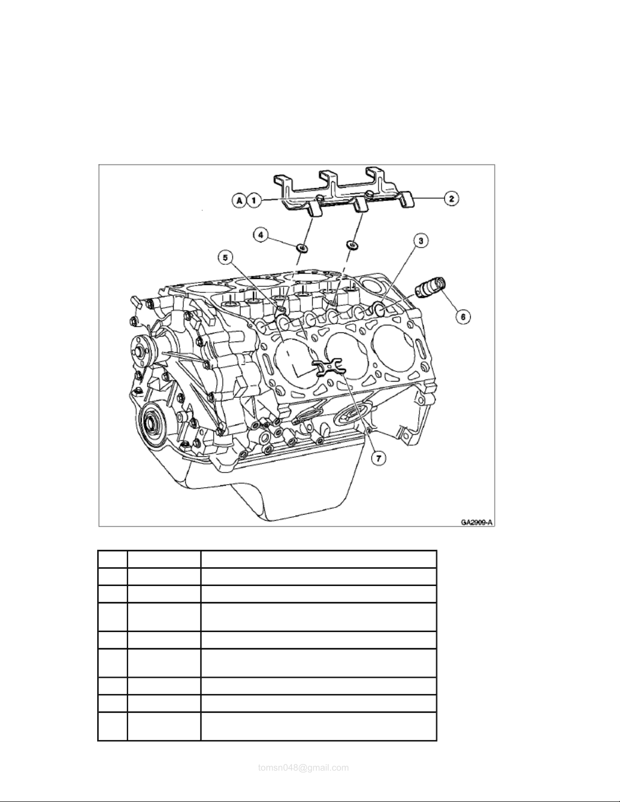
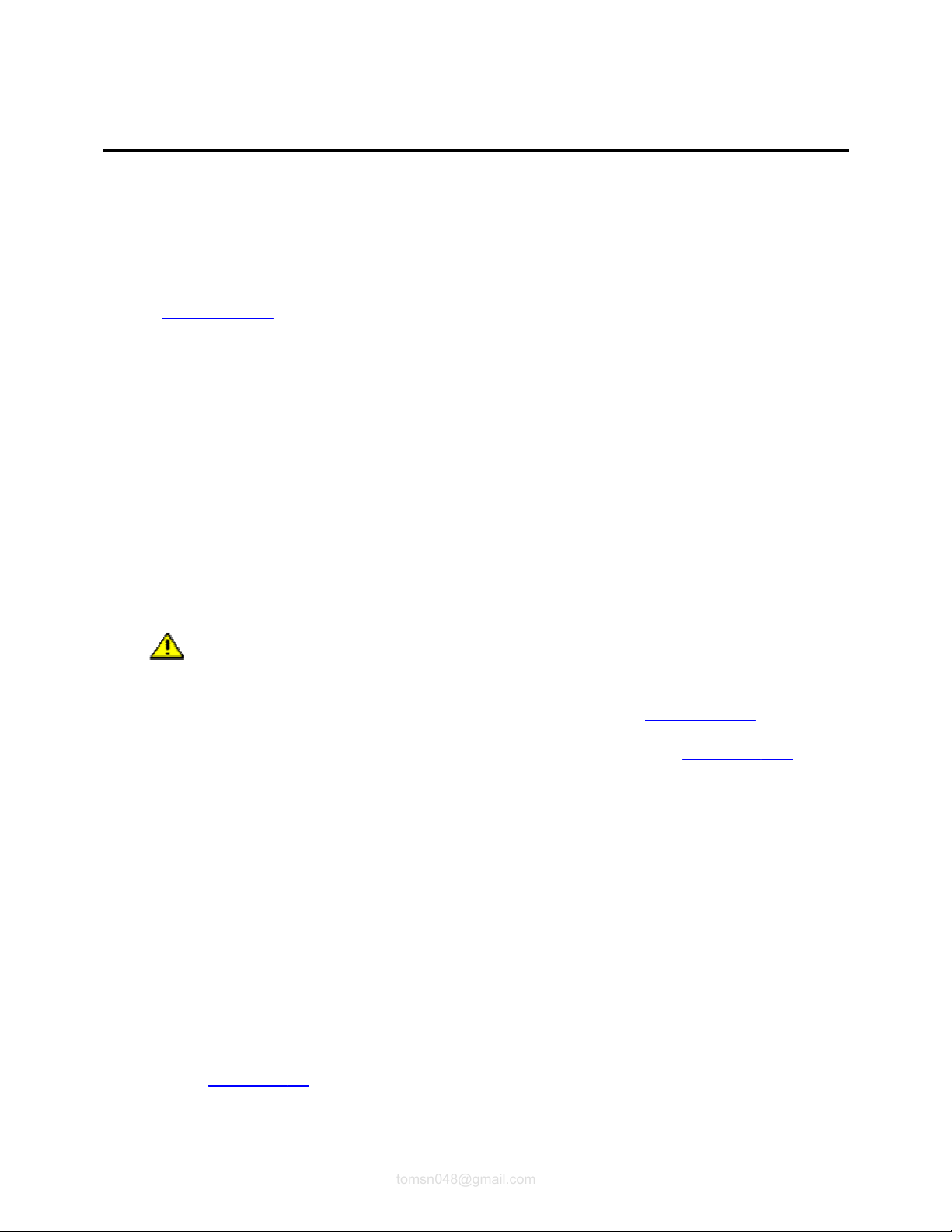
Fuel Rail and Injectors to Intake Manifold, Installation
Item Part Number Description
1 — Outlet End (Part of 9F593)
2 9F593 Fuel Injector
3 — Inlet End (Part of 9F593)
4 — Black Shipping Cap
(Part of 9F593)
5 — Green Shipping Cap
(Part of 9F593)
6 N802353-S100 Bolt
7 9F792 Fuel Injection Supply Manifold
8 9424 Intake Manifold
A — Tighten to 8-12 Nm
(71-106 Lb-In)

Page
4
of 91997 Aerostar/Ranger
2011
-04-27file://C:\TSO\tsocache\VDTOM_5368\SVK~us~en~file=SVK31B17.HTM~gen~ref.HTM
tomsn048@gmail.com
Installation
NOTE: Lightly oil all retaining bolt and stud threads before installation.
CAUTION: Aluminum components gouge easily which may cause gasket to leak. Always use
care when scraping aluminum gasket surfaces.
1. Clean mating gasket surfaces of intake manifold and cylinder blocks. Lay a clean cloth or shop rag in
the tappet valley to catch any gasket material. After scraping, carefully lift cloth from tappet valley
preventing any particles from entering oil drain holes or cylinder head. Use a suitable solvent to
remove old rubber sealant.
2. If installing new intake manifold, transfer:
Fuel injectors
Fuel injection supply manifold
Engine coolant temperature sensor
Water thermostat (8575)
Water thermostat housing
Hot water heater elbow connection (18599) by-pass fitting (18599).
Coolant temperature sending unit
3. Apply a 5-6mm drop of Silicone Rubber D6AZ-19562-AA or -BA or equivalent meeting Ford
specification ESB-M4G92-A or ESE-M4G195-A to intersection of cylinder blocks and cylinder head
(6049) at four corners as shown in the illustration.
4. Position intake manifold gaskets (9439) onto cylinder heads. Align the intake gasket locking tabs to
the provisions on the cylinder head gaskets as shown in the illustration.
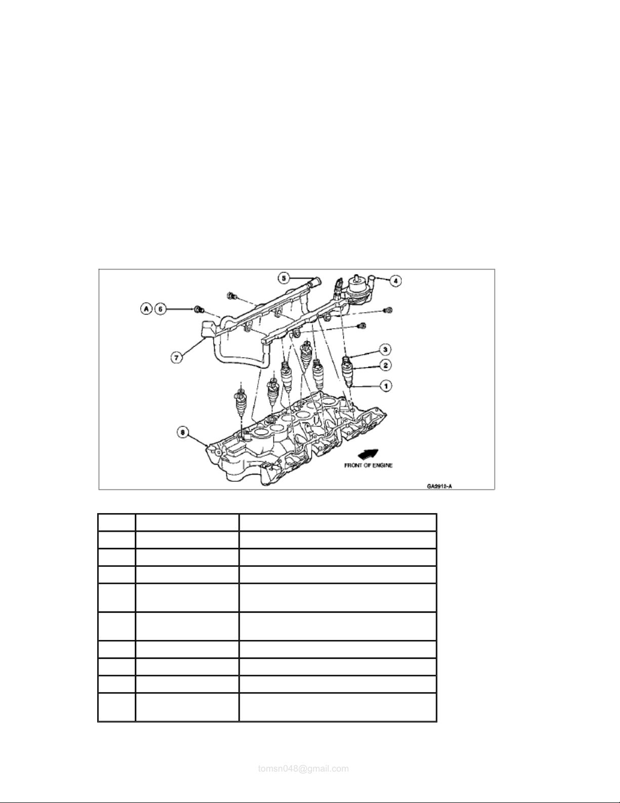
Intake Manifold Gasket, Installation
Page
5
of 91997 Aerostar/Ranger
2011
-04-27file://C:\TSO\tsocache\VDTOM_5368\SVK~us~en~file=SVK31B17.HTM~gen~ref.HTM
tomsn048@gmail.com
Item Part Number Description
1 9A424 Seal, Intake Manifold, Rear
2 — Distributor Hole
(Part of Cylinder Block)
3 6049 Cylinder Head
4 ESE-M4G195-B Sealer (4 places)
5 6010 Cylinder Blocks
6 9A424 Seal, Intake Manifold, Front
7 6051 Head Gasket
8 9439 Intake Manifold Gasket
5. Install front and rear intake manifold seals as shown in the illustration. Secure with retaining features.
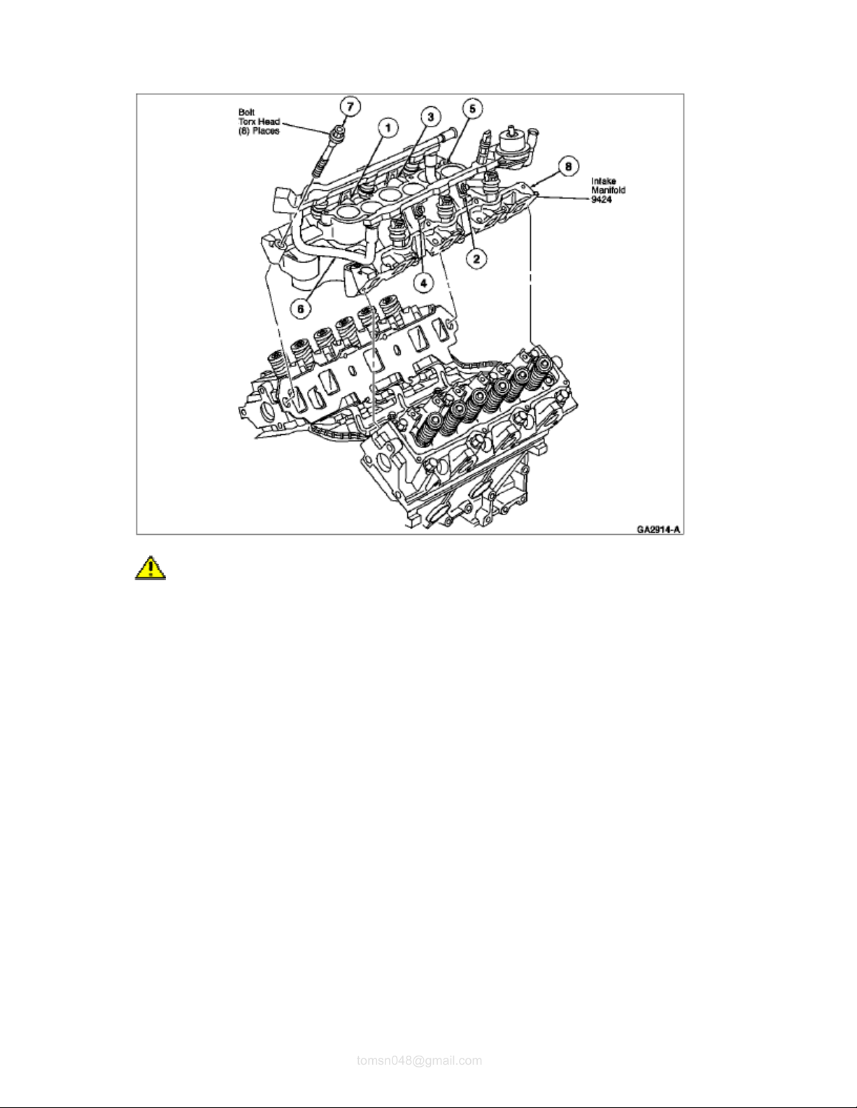
6. Lower intake manifold into position aligning manifold bolt holes to those in the cylinder head. Use
care to prevent disturbing the rubber sealer which can cause sealing voids. Install bolts 1, 2, 3 and 4
and hand-snug. Install remaining bolts and tighten in a two-step process. Tighten in numerical
sequence to 15 Nm (11 lb-ft), then again to 26-32 Nm (19-24 lb-ft).
Intake Manifold Bolt Torquing Sequence
Page
6
of 91997 Aerostar/Ranger
2011
-04-27file://C:\TSO\tsocache\VDTOM_5368\SVK~us~en~file=SVK31B17.HTM~gen~ref.HTM
tomsn048@gmail.com
7. CAUTION: If a new distributor or camshaft position sensor is installed, be sure to add the
rest of the pint of Engine Assembly Lubricant D9AZ-19579-D or equivalent meeting Ford
specification ESR-M99C80-A to the engine oil by pouring it through the distributor hole onto
the cam drive gear. Run engine at idle for five minutes before driving vehicle.
Dip entire distributor or camshaft position sensor drive gear in Engine Assembly Lubricant D9AZ19579-D or equivalent meeting Ford specification ESR-M99C80-A.
8. NOTE: Rocker arm fulcrum must be fully seated into cylinder head and push rod must be fully
seated in rocker arm and lifter sockets prior to final tightening.
Apply Engine Assembly Lubricant D9AZ-19579-D or equivalent meeting Ford specification ESRM99C80-A to cylinder No. 3 intake valve push rod and rocker arm. Install push rod. Move rocker arm
into position with push rod and snug rocker arm bolt. Rotate crankshaft (6303) to position camshaft
lobe straight down and away from valve tappet (6500). Tighten retaining bolt to 11 Nm (8 lb-ft) to seat
rocker arm fulcrum into cylinder head. Final-tighten bolt to 26-38 Nm (19-28 lb-ft) in any position.
9. Install valve covers as outlined in this section.
10. Install fuel charging wiring (9D930) to each fuel injector. Secure with standoffs to inboard rocker arm
cover studs.
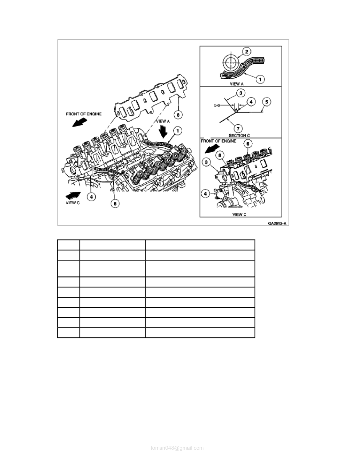
Ignition Coil Installation
Page
7
of 91997 Aerostar/Ranger
2011
-04-27file://C:\TSO\tsocache\VDTOM_5368\SVK~us~en~file=SVK31B17.HTM~gen~ref.HTM
tomsn048@gmail.com
Item Part Number Description
1 — Nut (Part of 12A310)
2 9J472 EGR Vacuum Regulator Bracket
3 — Nut (Part of 12A310)
Page
8
of 91997 Aerostar/Ranger
2011
-04-27file://C:\TSO\tsocache\VDTOM_5368\SVK~us~en~file=SVK31B17.HTM~gen~ref.HTM
tomsn048@gmail.com
4 12A310 Ignition Coil and Bracket Assembly
5 — Stud (Part of 9E926)
6 12N004 Ignition Coil Mounting Bracket
7 — Exhaust Manifold Stud
(Part of 9430)
A — Tighten to 8-12 Nm
(6-9 Lb-Ft)
B — Tighten to 16-20 Nm
(12-15 Lb-Ft)
11. Installthrottle body and newintake manifold gasketas outlined in Section 03-04B . Install coil and
bracket assembly (Ranger only). Tighten retaining nuts to 16-20 Nm (12-15 lb-ft).
12. Install wire harness standoffs to rocker arm cover studs and connect wires to spark plug and ignition
coil.
13. Install fuel supply and return lines to fuel injection supply manifold as outlined in Section 03-04B .
14. Install fuel tube clips.
15. Install upper radiator hose and heater water hoses. Tighten hose clamps securely.
16. Connect vacuum lines to premarked locations.
17. Connect electrical connections of:
Radio ignition interference capacitor
Idle air control valve
Engine coolant temperature sensor
Distributor
Ignition coil
Radio ignition interference capacitor
Water temperature indicator sender unit
EGR pressure sensor, if equipped
EGR vacuum regulator control, if equipped
Refer to Section 18-01 for further information.
18. NOTE: Engine coolant is corrosive to all engine bearing material. Replacing oil after removal
of a coolant carrying component prevents failure later.
Fill and bleed cooling system with specified coolant and proper mixture.
19. Replace crankcase oil and oil filter.
20. Install air cleaner outlet tube to throttle body and MAF sensor (12B579). Tighten retaining clamps to
1.9 Nm (17 lb-in).
21. Install closure hose to valve cover and air cleaner outlet tube.

22. NOTE: When the battery has been disconnected and reconnected, some abnormal drive
Page
9
of 91997 Aerostar/Ranger
2011
-04-27file://C:\TSO\tsocache\VDTOM_5368\SVK~us~en~file=SVK31B17.HTM~gen~ref.HTM
tomsn048@gmail.com
symptoms may occur while the powertrain control module (PCM) (12A650) relearns its
adaptive strategy. The vehicle may need to be driven 16 km (10 miles) or more to relearn the
strategy.
Connect ground cable at battery.
23. Start engine (6007) and check for coolant, oil, fuel and vacuum leaks.
24. Verify and correct default base initial engine timing to 10 degrees BTDC. Refer to the Powertrain
Control/Emissions Diagnosis Manual. Tighten retaining bolt to 19-30 Nm (14-22 lb-ft).

Section 03-01B: Engine, 3.0L V-6 1997 Aerostar, Ranger Workshop Manual
Page
1
of 81997 Aerostar/Ranger
2011
-04-27file://C:\TSO\tsocache\VDTOM_5368\SVK~us~en~file=SVK31B18.HTM~gen~ref.HTM
tomsn048@gmail.com
IN-VEHICLE SERVICE
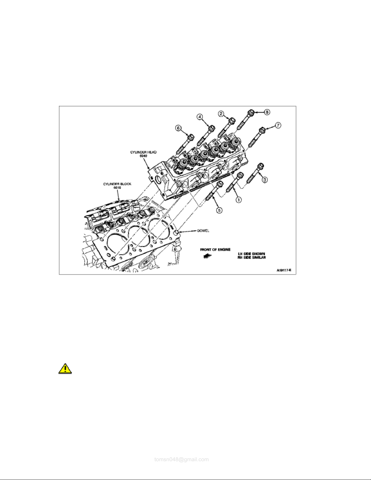
Cylinder Head(s)
Removal
1. NOTE: On 3.0L Aerostar it is necessary to remove the engine (6007) from the vehicle to
perform this procedure. Refer to Engine Assembly, Aerostar
section.
Disconnect ground cable at battery and set aside.
2. Drain cooling system. Refer to Section 03-03 .
3. Remove:
Engine air cleaner outlet tube
Engine air cleaner
PCV closure hose
, Removal and Installation, in this
4. Remove throttle body (9E926) as outlined in Section 03-04B .
5. Remove engine oil filler adapter (Aerostar only).
6. Disconnect fuel lines as outlined in Section 03
-04B .
7. Mark vacuum line location and remove lines.
8. Disconnect upper radiator hose and heater water hoses and move out of the way.
9. Disconnect spark plug wires from spark plugs with a turning motion and remove spark plug wire
separators from valve cover retaining pins.
10. Remove ignition coil and bracket from top of throttle body and pencil at exhaust manifold.
11. Remove spark plugs (12405) and bring number one piston to top dead center of the compression
stroke.
12. Remove intake manifold (9424) as outlined.
13. Remove engine accessory drive belt (8620).
14. On Ranger only:
a. Recover refrigerant from A/C system. Refer to Section 12
-00 .
b. Disconnect liquid line at condenser and suction hose from accumulator.
c. Plug or cap all openings in the air conditioning system to keep dirt, foreign material and excess
moisture out of the system.
d. Remove 4 bolts securing A/C compressor to power steering pump support bracket and remove
A/C compressor and hoses assembly from vehicle.
15. If left cylinder head is being removed, perform the following:
Page
2
of 81997 Aerostar/Ranger
2011
-04-27file://C:\TSO\tsocache\VDTOM_5368\SVK~us~en~file=SVK31B18.HTM~gen~ref.HTM
tomsn048@gmail.com
a. Remove fuel line retaining bracket from stud bolt on left side of power steering pump support
bracket and remove stud bolt.
b. Loosen lower bolt on left side of power steering pump support bracket two or three turns, but
DO NOT REMOVE.
c. Remove three bolts securing power steering pump support bracket to front of left cylinder head
and carefully allow power steering pump and bracket to tilt forward.
d. Remove engine oil level indicator tube attaching nut from exhaust manifold stud. Remove oil
level indicator tube from exhaust manifold.
16. If right cylinder head (6049) is being removed, perform the following:
a. Disconnect wiring from generator.
b. Remove three generator bracket and adjusting arm retaining bolts. Remove generator/bracket
assembly from vehicle.
17. Remove exhaust inlet pipe or pipes and exhaust manifolds (9430) and exhaust manifold.
18. Loosen rocker arm bolts and remove rocker arm assemblies. Identify the location of each assembly.
The rocker arm assemblies must be installed in their original location during reassembly.
19. Remove push rods (6565). Identify the position of each rod. The push rods should be installed in their
original position during reassembly.
20. Remove cylinder head retaining bolts.
21. Remove cylinder heads.
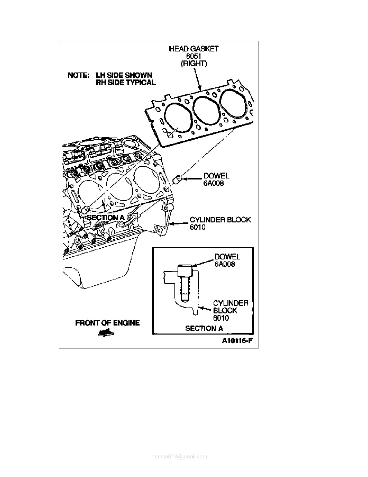
22. Remove head gaskets (6051) and discard.
nstallation
I
NOTE: Lightly oil all bolt and threads before installation. Always use new bolts when installing a
cylinder head.
1. CAUTION: Aluminum components gouge easily. Gouges in aluminum components will
cause gaskets to leak.
Lay a clean shop rag in lifter valley to catch any gasket particles. Clean cylinder head, intake manifold
and cylinder head to block gasket surfaces. After scraping, lift cloth so no gasket material falls into
lifter valley. If the cylinder head was removed for a head gasket replacement, check the flatness of
the cylinder head and block gasket surfaces. Refer to Section 03-00 .
2. NOTE: Replace alignment dowels if damaged.
Position head gaskets on cylinder blocks (6010) using the dowels for alignment. Make sure gasket is
aligned as shown in the illustration.
be checked for tightness if desired.
Page
3
of 81997 Aerostar/Ranger
2011
-04-27file://C:\TSO\tsocache\VDTOM_5368\SVK~us~en~file=SVK31B18.HTM~gen~ref.HTM
tomsn048@gmail.com
3. Carefully position cylinder heads on cylinder blocks.
4. Install new cylinder head retaining bolts and hand tighten.
5. Tighten retaining bolts in sequence as illustrated to 80 Nm (59 lb-ft).
6. Back off all bolts a minimum of one full turn (360 degrees).
7. NOTE: When the cylinder head retaining bolts have been tightened using this procedure, it is
not necessary to retighten the bolts after extended engine operation. However, the bolts can
Retighten the cylinder head retaining bolts in sequence in two tightening steps as follows:
required.
Page
4
of 81997 Aerostar/Ranger
2011
-04-27file://C:\TSO\tsocache\VDTOM_5368\SVK~us~en~file=SVK31B18.HTM~gen~ref.HTM
tomsn048@gmail.com
45-55 Nm (33-41 lb-ft)
85-99 Nm (63-73 lb-ft)
Cylinder Head Assembly, Installation
8. Install intake manifold as outlined in this section.
9. Dip each push rod Engine Assembly Lubricant D9AZ-19579-D or equivalent meeting Ford
specification ESR-M99C80-A heavy engine oil. Install push rods in their original positions and
orientation.
10. Loosely install rocker arm assemblies in original locations. Apply Engine Assembly Lubricant D9AZ19579-D or equivalent meeting Ford specification ESR-M99C80-A heavy engine oil. Tighten rocker
arm fulcrum bolts to 10-12 Nm (8-10 lb/ft) while lifter is on base circle of corresponding cam lobe.
Final tighten rocker arm fulcrum bolts to 26-38 Nm (20-28 lb/ft).
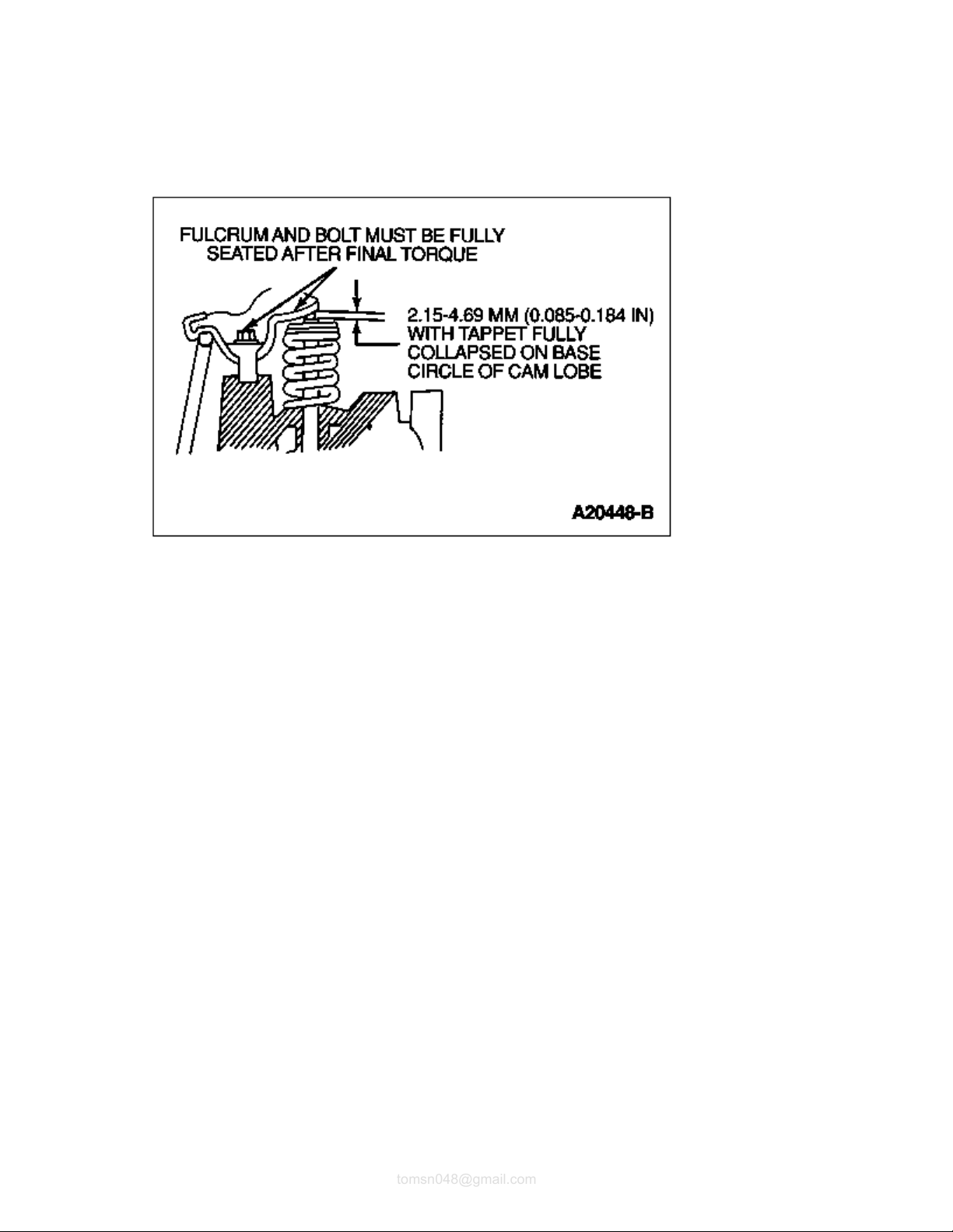
11. CAUTION: Rocker arm fulcrum must be fully seated into cylinder head and push rods
must be fully seated in lifter and rocker arm sockets during final tightening.
NOTE: With number one piston at top dead center (TDC) of the exhaust stroke, you can tighten
intake rockers of cylinder numbers 1 and 4, and exhaust rockers of cylinder 2 and 5. With the
crankshaft rotated so number one piston is 135 degs. after top dead center (ATDC) of the
exhaust stroke, you can tighten intake rockers of cylinder numbers 2, 3, 5 and 6, and exhaust
rockers of cylinder numbers 1, 3, 4 and 6.
NOTE: If the original valve train components are being reused, a valve clearance check is not
You must check rocker arm to valve tip clearance if a cam, lifters, push rods, rocker arms, rocker arm
Page
5
of 81997 Aerostar/Ranger
2011
-04-27file://C:\TSO\tsocache\VDTOM_5368\SVK~us~en~file=SVK31B18.HTM~gen~ref.HTM
tomsn048@gmail.com
fulcrums or valves are replaced, or valves are ground.
12. Install valve covers as outlined in this section.
13. Install exhaust manifolds as outlined in this section. Tighten retaining bolts to 20-30 Nm (15-22 lb/ft).
Install inlet pipe retaining nuts, tighten to 39-42 Nm (30-32 lb/ft).
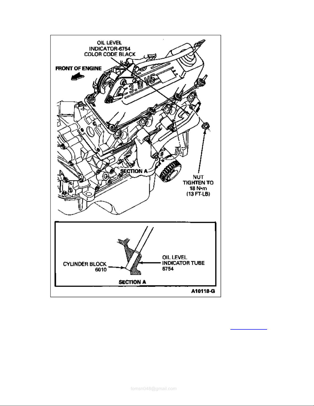
14. Apply Cup Plug Sealer meeting Ford specification ESE-M4621-A or equivalent to cylinder block.
Install oil level indicator tube into cylinder block. Oil level indicator tube must bottom out as illustrated.
Tighten oil level indicator tube retaining nut at exhaust manifold stud bolt to 16-20 Nm (12-14 lb/ft).
Page
6
of 81997 Aerostar/Ranger
2011
-04-27file://C:\TSO\tsocache\VDTOM_5368\SVK~us~en~file=SVK31B18.HTM~gen~ref.HTM
tomsn048@gmail.com
15. Install fuel charging wiring (9D930) to fuel injectors and inboard rocker arm cover studs. Connect fuel
charging wiring to engine control sensor wiring (12A581) and secure with retaining features.
16. Install throttle body and new intake manifold gasket (9439) as outlined. Refer to Section 03-04B .
17. If left cylinder head was removed, perform the following:
a. Install three bolts securing power steering pump support bracket to front of left cylinder head,
finger tight only.
b. Install stud bolt at left side of power steering pump support bracket. Tighten all five bolts
securing power steering pump support bracket to engine block and cylinder head to 40-62 Nm

(30-46 lb/ft).
strategy.
Page
7
of 81997 Aerostar/Ranger
2011
-04-27file://C:\TSO\tsocache\VDTOM_5368\SVK~us~en~file=SVK31B18.HTM~gen~ref.HTM
tomsn048@gmail.com
c. Install fuel line retaining bracket to stud bolt on left side of power steering pump support
bracket and secure with nut. Tighten nut to 16-20 Nm (12-15 lb/ft).
18. If right cylinder head was removed, perform the following:
a. Install generator (GEN) (10300) and generator bracket assembly. Tighten three retaining bolts
to 48 Nm (35 lb-ft).
b. Install generator brace and tighten nuts to 26-35 Nm (20-25 lb-ft).
c. Connect generator voltage regulator wiring.
19. On Ranger only:
a. Position A/C compressor and hose assembly on power steering pump support bracket. Install
4 bolts securing A/C compressor to power steering pump support bracket and tighten four
fasteners to 21-29 Nm (15-21 lb/ft).
b. Remove plugs and caps from all openings in the air conditioning system.
c. Connect liquid line at condenser and suction hose to accumulator.
d. Evacuate and recharge A/C system. Refer to Section 12
20. Install engine accessory drive belt.
21. Install ignition coil and bracket assembly to throttle body stud bolts and pencil brace at exhaust
manifold. Tighten three nuts to 16-20 Nm (12-14 lb/ft).
-00 .
22. Connect fuel lines to fuel injection supply manifold (9F792) as outlined in Section 03-04A . Install fuel
tube clips.
23. Connect upper radiator hose and heater water hoses. Tighten hose clamps securely. Refer to Section
03-03 .
24. Connect vacuum lines to premarked locations.
25. Install engine oil filler adapter (Aerostar only).
26. NOTE: Engine coolant is corrosive to all engine bearing material. Replacing engine oil after
removal of a coolant-carrying component prevents failure later.
Drain and change engine oil.
27. Install air cleaner outlet tube to throttle body and engine air cleaner (ACL) (9600). Tighten clamps
securely. Refer to Section 03-12 .
28. Install closure hose at air cleaner outlet tube and valve cover (6582).
29. CAUTION: This engine has aluminum components and requires a special corrosion-
inhibiting coolant formulation to avoid radiator damage. Refer to Section 03-03 for coolant
specifications.
Fill and bleed cooling system.
30. NOTE: When the battery has been disconnected and reconnected, some abnormal drive
symptoms may occur while the powertrain control module (PCM) (12A650) relearns its
adaptive strategy. The vehicle may need to be driven 16 km (10 miles) or more to relearn the

Connect ground cable at battery.
Page
8
of 81997 Aerostar/Ranger
2011
-04-27file://C:\TSO\tsocache\VDTOM_5368\SVK~us~en~file=SVK31B18.HTM~gen~ref.HTM
tomsn048@gmail.com
31. Start engine and check for coolant, fuel, oil, vacuum and exhaust leaks.
32. Verify base ignition timing as outlined.
33. Check and, if necessary, adjust speed control linkage.
Section 03-01B: Engine, 3.0L V-6 1997 Aerostar, Ranger Workshop Manual
A
Vibration Damper and Seal Replacer
Page
1
of 31997 Aerostar/Ranger
2011
-04-27file://C:\TSO\tsocache\VDTOM_5368\SVK~us~en~file=SVK31B19.HTM~gen~ref.HTM
tomsn048@gmail.com
IN-VEHICLE SERVICE
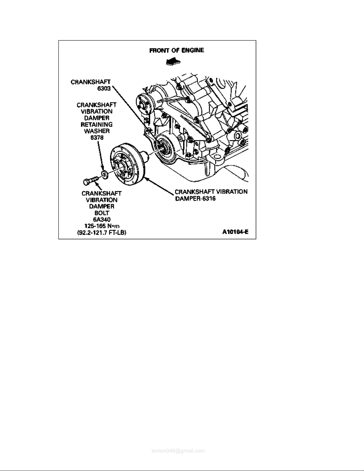
Crankshaft Pulley/Vibration Damper/Crankshaft Front Seal
SPECIAL SERVICE TOOL(S) REQUIRED
Description Tool Number
Front Cover Seal Replacer T70P-6B070Crankshaft Damper Remover T58P-6316-D
Vibration Damper Remover Adapter T82L-6316-B
T82L-6316-A
Removal
1. Disconnect ground cable at battery and set aside.
2. Remove air cleaner outlet tube assembly.
3. Remove drive belts.
4. Remove four pulley-to-damper retaining bolts.
5. Remove crankshaft pulley (6312).
6. Remove crankshaft vibration damper bolt and crankshaft vibration damper washer.
7. Remove crankshaft vibration damper from crankshaft (6303) using Crankshaft Damper Remover
T58P-6316-D and Vibration Damper Remover Adapter T82L-6316-B.
8. Pry crankshaft front seal (6700) from engine front cover (6019) with a flat-bladed screwdriver or other
similar tool. Use care to prevent damage to engine front cover and crankshaft.
strategy.
Page
2
of 31997 Aerostar/Ranger
2011
-04-27file://C:\TSO\tsocache\VDTOM_5368\SVK~us~en~file=SVK31B19.HTM~gen~ref.HTM
tomsn048@gmail.com
Installation
1. Inspect front cover and shaft seal surface of the crankshaft damper for damage, nicks, burrs or other
roughness which may cause the new seal to fail. Service or replace components as necessary.
2. Lubricate seal lip with clean engine oil and install crankshaft front seal using Vibration Damper and
Seal Replacer T82L-6316-A and Front Cover Seal Replacer T70P-6B070-A.
3. Coat crankshaft damper sealing surface with clean engine oil. Apply RTV F4AZ-19562-B or
equivalent meeting Ford specification WSE-M4G323-A1 using Rotunda Gasket Gun with Regulator
071-R0001 or equivalent to keyway of damper prior to installation. Install crankshaft vibration damper
using Vibration Damper and Seal Replacer T82L-6316-A. Install crankshaft vibration damper bolt and
crankshaft vibration damper washer and tighten to 125-165 Nm (92-122 lb-ft).
4. Position crankshaft pulley and install attaching bolts. Tighten attaching bolts to 32 Nm (24 lb-ft).
5. Install engine (6007) accessory drive belt (8620) and route as illustrated. Check to ensure drive belt is
riding in ribbed pulley correctly or early failure will result.
6. Install air cleaner outlet tube.
7. NOTE: When the battery has been disconnected and reconnected, some abnormal drive
symptoms may occur while the powertrain control module (PCM) (12A650) relearns its
adaptive strategy. The vehicle may need to be driven 16 km (10 miles) or more to relearn the
 Loading...