

Page 1
Page 2

Page 3

Table of Contents
Introductory Information ............... 1
Safety Restraints ................... 7
Starting Your Windstar ................55
Warning Lights and Gauges ..............65
Instrument Panel Controls .............. 105
Steering Column Controls .............. 129
Features ...................... 143
Electronic Sound Systems .............. 195
Driving Your Windstar ............... 235
Roadside Emergencies ................ 261
Customer Assistance ................ 283
Reporting Safety Defects ............. 290
Accessories ..................... 295
Servicing Your Windstar ............... 301
Quick Index .................... 371
Index........................ 381
Service Station Information ............. 396
Page 4

Introductory Information
At Ford Motor Company, excellence is the continuous
commitment to achieve the best result possible. It is dedication
to learning what you want, determination to develop the right
concept, and execution of that concept with care, precision, and
attention to detail. In short, excellence means being the standard
by which others are judged.
Our Guiding Principles
■ Quality comes first. For your satisfaction, the quality of our
products and services must be our number one priority.
■ You are the focus of everything we do. Our work must be
done with you in mind, providing better products and
services than our competition.
■ Continuous improvement is essential to our success. We
must strive for excellence in everything we do: in our
products — in their safety and value — and in our services,
our human relations, our competitiveness, and our
profitability.
■ Employee involvement is our way of life. We are a team.
We must treat one another with trust and respect.
■ Dealers and suppliers are our partners. We must maintain
mutually beneficial relationships with dealers, suppliers, and
our other business associates.
■ Integrity is never compromised. Our conduct worldwide
must be pursued in a manner that is socially responsible and
Page 5

Congratulations on the purchase of your new vehicle. This
guide has information about the equipment and the options for
your new vehicle. You may not have bought all of the options
available to you. If you do not know which information applies
to your vehicle, talk to your dealer.
This guide describes equipment and gives specifications for
equipment that was in effect when this guide was approved for
printing. Ford may discontinue models or change specifications
or design without any notice and without incurring obligation.
NOTES and WARNINGS
NOTES give you additional information about the subject
matter you are referencing.
WARNINGS remind you to be especially careful in those areas
where carelessness can cause damage to your vehicle or
personal injury to yourself, your passengers or other people.
Please read all WARNINGS carefully.
RWARNING
Finding Information in This Guide
After you have read this guide once, you will probably return
to it when you have a specific question or need additional
information. To help you find specific information quickly, you
Page 6

Introductory Information
To use the Index, turn to the back of the book and search in the
alphabetical listing for the word that best describes the
information you need. If the word you chose is not listed, think
of other related words and look them up. We have designed the
Index so that you can find information under a technical term.
Canadian Owners — French Version
French Owner Guides can be obtained from your dealer or by
writing to Ford Motor Company of Canada, Limited, Service
Publications, P.O. Box 1580, Station B, Mississauga, Ontario L4Y
4G3.
Booklet
The Maintenance Schedule and Record booklet lists the services
that are most important for keeping your vehicle in good
condition. A record log is also provided to help you keep track
of all services performed.
Your vehicle is covered by three types of warranties: Basic
Vehicle Warranty, Extended Warranties on certain parts, and
Emissions Warranties.
Read your Warranty Information Booklet carefully to find out
about your vehicle’s warranties and your basic rights and
responsibilities.
If you lose your Warranty Information Booklet, you can get a new
one free of charge. Contact any Ford or Lincoln-Mercury dealer,
Page 7

Buying a Ford Extended Service Plan
If you bought your vehicle in the U.S., you can buy a Ford
Extended Service Plan for your vehicle. This optional contract
provides service protection for a longer period of time than the
basic warranty that comes with your vehicle.
You do not have to buy this option when you buy your vehicle.
However, your option to purchase the Ford Extended Service
Plan runs out after 18 months or 18,000 miles. See your dealer
for more details about the Ford Extended Service Plan.
If you purchased a Canadian vehicle and did not take
advantage of the Ford Extended Service Plan at the time of
purchase, you may still be eligible. See your dealer for the
details.
Your new vehicle goes through an adjustment or break-in
period during the first 1,000 miles (1,600 km) that you drive it.
During the break-in period, you need to pay careful attention to
how you drive your vehicle.
■ Avoid sudden stops. Because your vehicle has new brake
linings, you should take these steps:
— Watch traffic carefully so that you can anticipate when to
stop.
— Begin braking well in advance.
— Apply the brakes gradually.
Page 8

Introductory Information
■ Wheel lug nuts must be retightened to proper torque
specifications at 500 miles/800 km of new vehicle operation.
Proper torque specifications are provided in this guide. Also
retighten to proper torque specification at 500 miles/800 km
after any wheel change or any other time the wheel lug nuts
have been loosened.
■ Use only the type of engine oil that Ford recommends. See
Engine oil recommendations in the Index. Do not use special
“break-in” oils.
Your vehicle is equipped with an Electronic Powertrain Control
Module that limits engine and/or vehicle speeds with a cut-out
mode to promote durability.
Washing and Polishing Your Vehicle
Wash the outside of your vehicle, including the underside, with
a mild detergent.
DO NOT:
■ Wash your vehicle with hot water
■ Wash your vehicle while it sits in direct sunlight
■ Wash your vehicle while the body is hot
Pollen, bird droppings and tree sap can damage the paint,
especially in hot weather. Wash your vehicle as often as
necessary to keep it clean.
Page 9

Paint damage resulting from fallout is not related to a defect in
paint materials or workmanship and therefore is not covered by
warranty. Ford, however, believes that continual improvement
in customer satisfaction is a high priority. For this reason, Ford
has authorized its dealers to repair, at no charge to the owner,
the surfaces of new vehicles damaged by environmental fallout
within 12 months or 12,000 miles (20,000 km) of purchase,
whichever comes first. Customers may be required to bring their
vehicle in for inspection by a Ford representative.
Polish your vehicle to remove harmful deposits and protect the
finish.
Cleaning Chrome and Aluminum Parts
Wash chrome and aluminum parts with a mild detergent. Do
not use steel wool, abrasive cleaners, fuel, or strong detergents.
Cleaning Plastic Parts
Some of your vehicle’s exterior trim parts are plastic. Clean with
a tar and road oil remover if necessary. Use a vinyl cleaner for
routine cleaning.
Do not clean plastic parts with thinners, solvents or
petroleum-based cleaners.
If you have your vehicle rustproofed, remove oversprayed
rustproofing with a tar and road oil remover. If rustproofing is
not removed from plastic and rubber parts, it can cause
deterioration.
Page 10

Safety Restraints
The use of safety belts helps to restrain you and your
passengers in case of a collision. In most states and in Canada,
the law requires their use. We strongly recommend that you use
them every time you travel in your vehicle.
Safety belts provide best restraint when:
■ the seatback is upright
■ the occupant is sitting upright (not slouched)
■ the lap belt is snug and low on the hips
■ the shoulder belt is snug against the chest
■ the knees are straight forward
See the following sections in this chapter for directions on how
to properly use these safety belts. Also see Safety Restraints for
Children in this chapter for special instructions about using
safety belts for children.
RWARNING
Make sure that you and your passengers, including
pregnant women, wear safety belts. Be sure that the lap
belt portion of your safety belt fits snugly and as low as
possible around the hips. If safety belts are not used
properly, the risk of you or your passengers being
injured in a collision greatly increases.
Page 11
RWARNING
Passengers should not be allowed to ride in the cargo
area. Persons not riding in a seat with a fastened seat
belt are much more likely to suffer serious injury in a
collision. Cargo should always be secured to prevent it
from shifting and causing damage to the vehicle or harm
to passengers.
RWARNING
Failure to follow these precautions could increase the risk
and/or severity of injury in a collision. 1) Use the
shoulder belt on the outside shoulder only. Never wear
the shoulder belt under the arm. 2) Never swing it
around your neck over the inside shoulder. 3) Never use
a single belt for more than one person.
RWARNING
To reduce the risk of serious injury in a collision, always
drive and ride with your seatback upright and the lap
belt snug and low across the hips.
RWARNING
To reduce the risk of serious injury in a collision,
children should always ride with the seatback upright.
Page 12
Safety Restraints
RWARNING
Never let a passenger hold a child on his or her lap
while the vehicle is moving. The passenger cannot
protect the child from injury in a collision.
RWARNING
Never use a single belt for more than one person or
across more than one seating position. This greatly
increases the risk that one or both of the people will be
injured in a collision. Each seating position in your
vehicle has a specific safety belt assembly which is made
up of one buckle and one tongue that are designed to be
used as a pair.
Lock the doors of your vehicle before driving to lessen the risk
of the door coming open in a collision.
While your vehicle is in motion, the combination lap and
shoulder belt adjusts to your movement. However, if you brake
hard, turn hard, or if your vehicle receives an impact of 5 mph
(8 km/h) or more, the lap/shoulder belt locks and helps reduce
your forward movement.
After you get into your vehicle, close the door and lock it. Then
adjust the seat to the position that suits you best.
Page 13
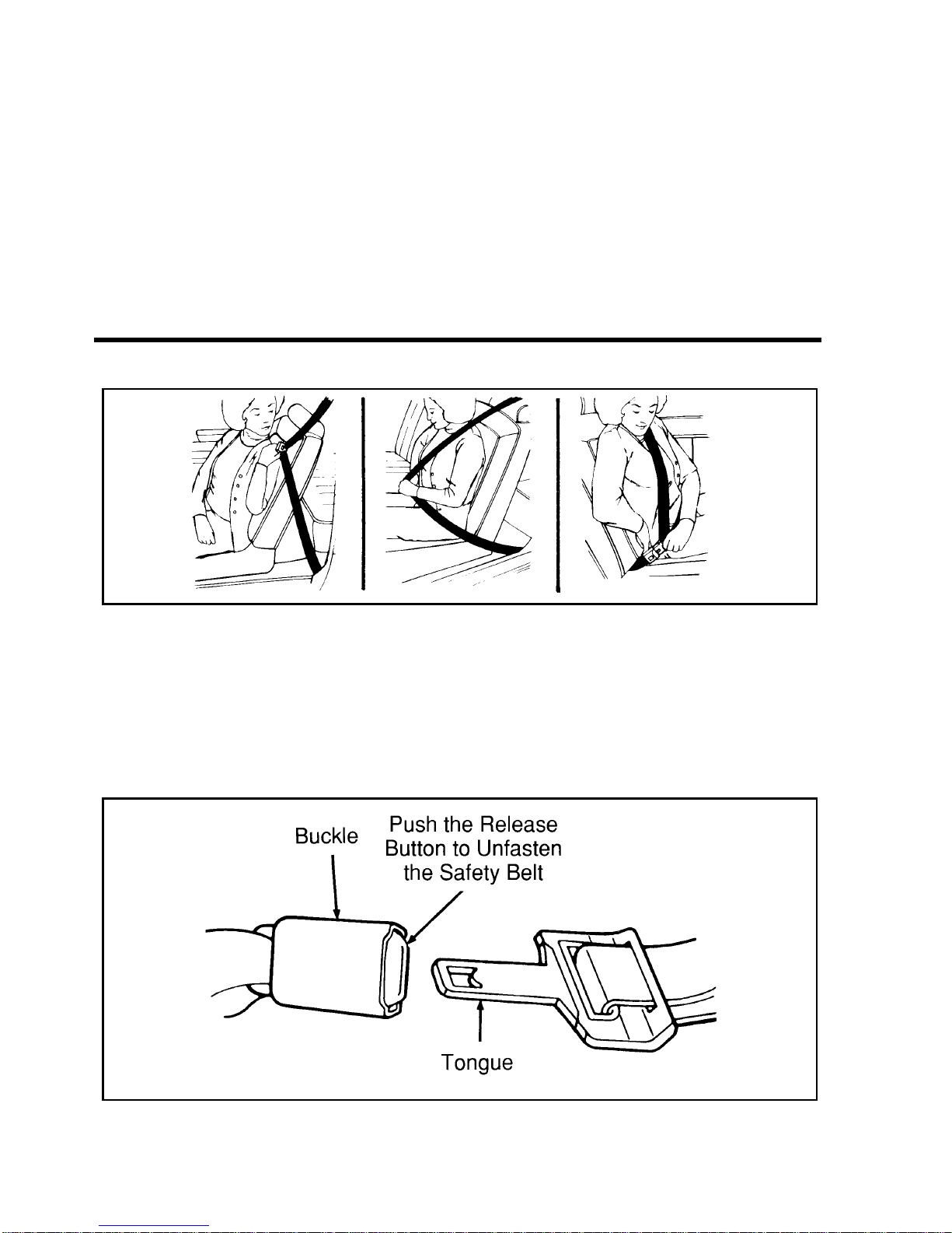
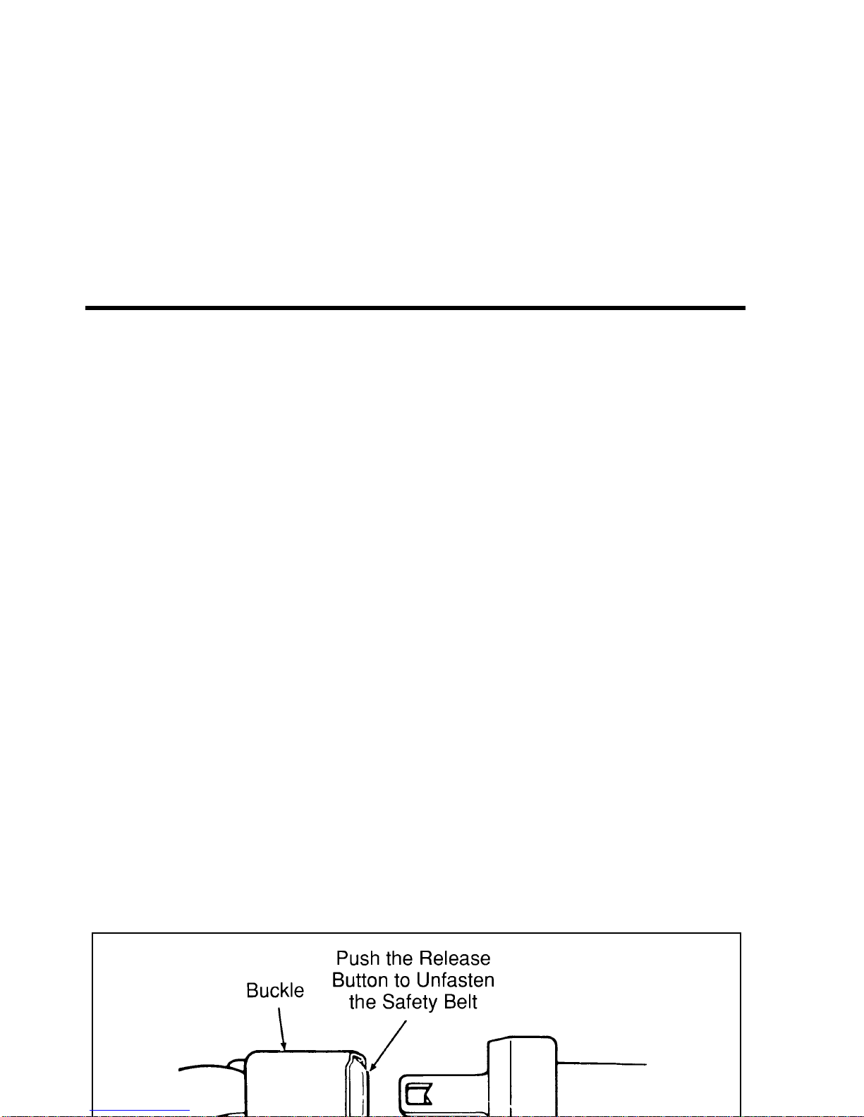
Fastening the front seat lap and shoulder belt
Adjust the lap part of the belt by pulling up on the shoulder
belt until the lap belt fits snugly and as low as possible around
your hips.
Push the release button on the buckle. This allows the tongue to
unlatch from the buckle.
Unfastening the combination lap and shoulder belts
While the belt retracts, guide the tongue to its original position
to prevent it from striking you or part of the vehicle.
Page 14

Safety Restraints
Shoulder Belt Adjustment (Driver and Right Front
Passenger)
You can adjust the shoulder belt height to one of five (5)
positions. To adjust, pinch the release button and slide it up or
down until the belt rests on your shoulder near your neck.
Release the button and make sure the adjuster is firmly seated
in one of the five (5) positions.
The shoulder belt height adjuster
Combination Lap and Shoulder Belt — Second Row
Bench Seat
There is a unique safety restraint system for the outside seating
position of the second row bench seat. It is very important that
you read and understand this section before anyone rides in the
outside seating position (near the sliding door) of the
two-passenger bench seat.
In addition to safety belt anchorages in the floor and roof
structures, the second row bench seat has a detachable safety
belt anchor mounted to the right window side of the seat. The
Page 15
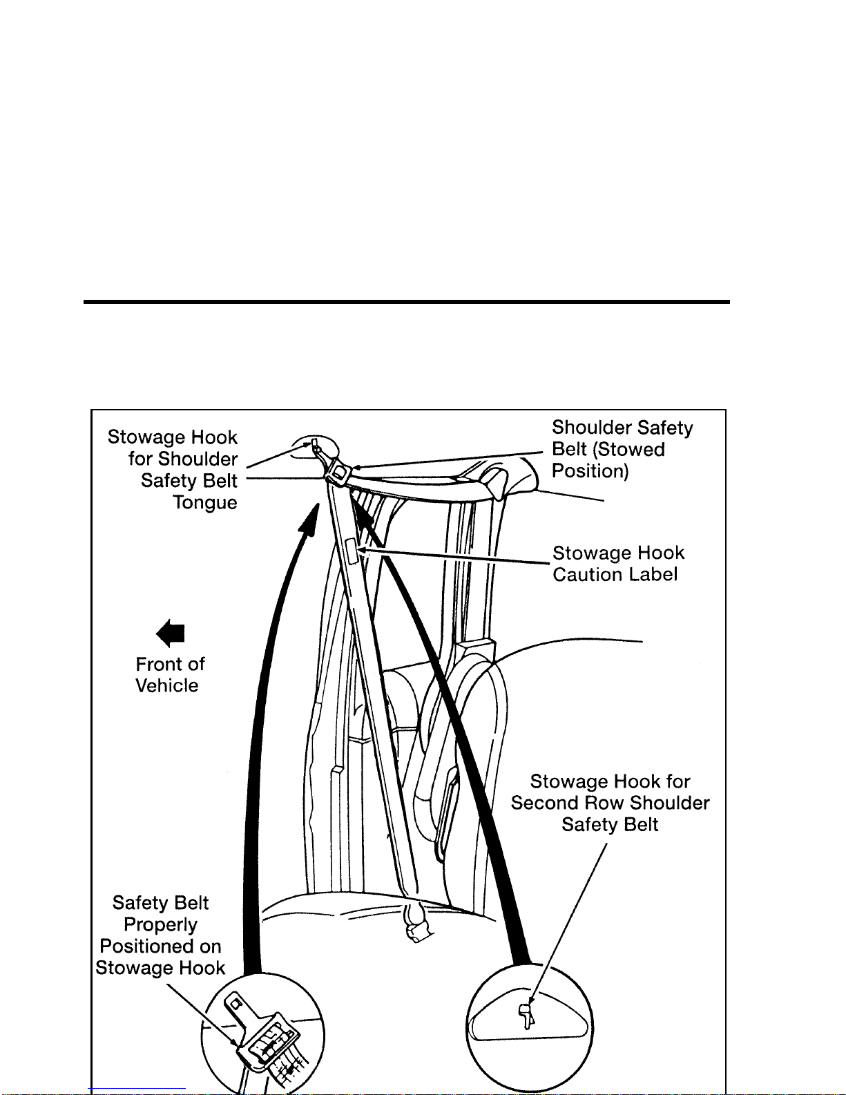
NOTE: When the belt is stowed usin g the hook, DO NOT use
the hanging belt as an assist when entering the vehicle.
Page 16

Safety Restraints
When removing the second row bench seat:
small screwdriver into the slot provided on the detachable
anchor (see Figure 1). When this shoulder belt assembly is free
of the seat, allow the retractor to wind up the slack in the belt.
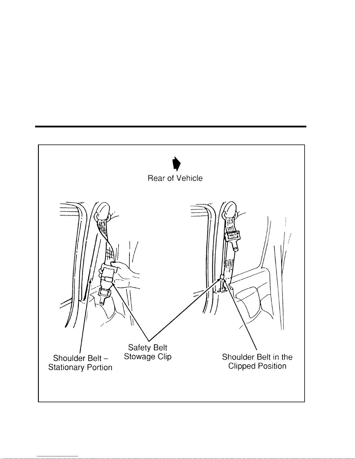
the end of the belt to the stationary portion of the shoulder
belt (see Figure 2). The end of the shoulder belt must be
clipped in order to keep it from striking anything during
vehicle operation.
Page 17
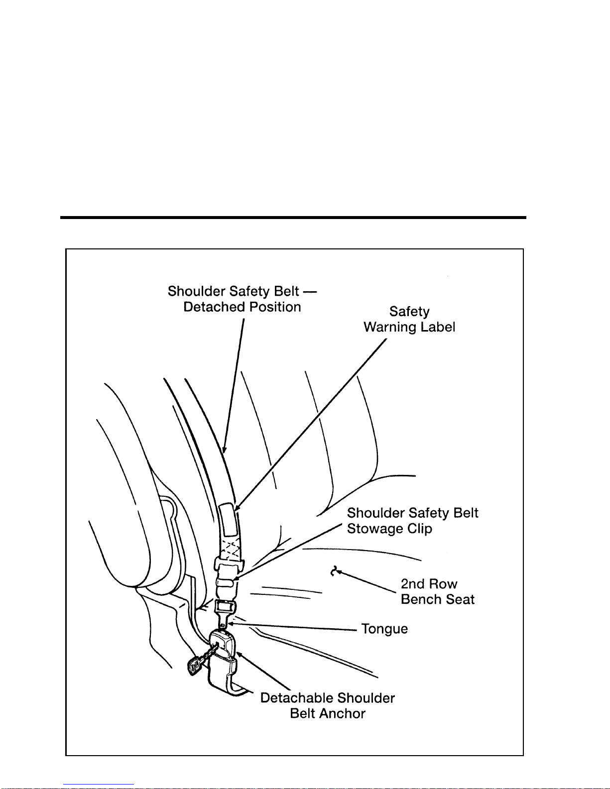
Figure 1: Second row bench seat detachable anchor
Page 18
Safety Restraints
Figure 2: Securing the detachable shoulder belt
Refer to the “Seats” section in the Features chapter of this
Owner Guide for information on removing and installing seats.
After re-installing the second row bench seat, make sure that the
Page 19
RWARNING
When reinstalling a rear seat in your vehicle it must be
placed in its original position. Improper installation of
the seat will prevent correct use of the safety belts and
could increase the risk of injury. Refer to the warning
label on the seat belt.
Your vehicle is equipped with a dual locking mode retractor on
the shoulder belt portion of the combination lap/shoulder safety
belt for front passenger and rear seat window passengers.
Dual locking mode retractors operate in two ways:
Vehicle Sensitive (Emergency) Locking Mode
In this operating mode, the shoulder belt retractor will allow the
occupant freedom of movement, locking tight only on hard
braking, hard cornering or impacts of approximately five mph
(8 km/h) or more.
Automatic Locking Mode
In this operating mode, the shoulder belt retractor will be
automatically locked and remain locked when the combination
lap/shoulder safety belt is buckled, and does not allow the
occupant freedom of movement. This mode provides the
following:
■ A tight lap/shoulder belt fit on occupant
■ Child seat or infant carrier restraint
Rear-facing infant seats should never be placed in the front seat.
This mode must be used when installing a child seat on the
front passenger seat and rear window seats where dual locking
Page 20
Safety Restraints
until all of the belt is extracted, and when allowed to retract,
a clicking sound will be heard. At this time, the belt retractor
is in the automatic locking mode (child restraint mode).
retract. This indicates that the retractor is in the automatic
locking mode.
NOTE: When the combination lap/shoulder belt is unbuckled
and allowed to retract completely, the retractor will
switch back to the vehicle sensitive (emergency)
locking mode. See detailed instructions under Safety
Seats for Children later in this chapter.
The lap belt in the center of the rear seat does not adjust
automatically. You must adjust it to fit snugly and as low as
possible around your hips. Do not wear it around your waist.
If you need to lengthen the belt, unfasten it and tip the belt
tongue at a right angle to the belt. Pull the belt tongue over
your lap until it reaches the buckle.
If you need to shorten the belt, pull on the loose end of the
webbing until the belt fits snugly.
To unfasten the belt, push the release button on the buckle.
Page 21

Check the safety belt systems periodically to make sure that
they work properly and are not damaged.
All safety belt assemblies, including retractors, buckles, front
seat belt buckle support assemblies (slide bar) (if so equipped),
child safety seat tether bracket assemblies (if so equipped), and
attaching hardware, should be inspected after any collision. Ford
recommends that all safety belt assemblies used in vehicles
involved in a collision be replaced. However, if the collision was
minor and a qualified technician finds that the belts do not
show damage and continue to operate properly, they do not
need to be replaced. Safety belt assemblies not in use during a
collision should also be inspected and replaced if either damage
or improper operation is noted.
Cleaning the Safety Belts
Clean the safety belts with any mild soap solution that is
recommended for cleaning upholstery or carpets. Do not bleach
or dye the belt webbing because this may weaken it.
Safety Belt Extension Assembly
For some people, the safety belt may be too short even when it
is fully extended. You can add about eight inches (20 cm) to the
belt length with a safety belt extension assembly (part number
611C22). Safety belt extensions are available at no cost from
your dealer.
RWARNING
Page 22
Safety Restraints
(SRS)
The driver and right front passenger air bags are Supplemental
Restraint Systems (SRS), provided at these seating positions in
addition to the lap/shoulder belt, and are designed to
supplement the protection provided to properly belted
occupants in moderate to severe frontal collisions. The
supplemental air bag system does not provide restraint to the
lower body.
The Importance of Wearing Safety Belts
RWARNING
Safety belts must be worn by all vehicle occupants to be
properly restrained and help reduce the risk of injury in
a collision.
RWARNING
All occupants of the vehicle, including the driver, should
always wear their safety belts, whether or not an airbag
Supplemental Restraint System is also provided at their
seating position. Failure to do so may increase the risk of
severe injury or death in the event of a collision.
There are four very important reasons to use safety belts even
with an air bag system. Use your safety belts to:
■ help keep you in the proper position (away from the air bag)
Page 23

■ reduce the risk of harm in frontal collisions that are not
severe enough to activate the supplemental air bag
■ reduce the risk of being thrown from your vehicle
The Importance of Being Properly Seated
In a collision, the air bag must inflate extremely fast to help
provide additional protection for you. In order to do this, the
air bag must inflate with considerable force. If you are not
seated in a normal riding position with your back against the
seatback, the air bag may not protect you properly and could
possibly hurt you as it inflates.
RWARNING
If a passenger is not properly seated and restrained, an
inflating air bag could cause serious injury.
Your vehicle is equipped with a right front passenger air bag.
Air bags deploy with great force, faster than the blink of an eye.
Front passengers, especially children and small adults, must
never sit on the front edge of the seat, stand near the glove
compartment of the instrument panel, or lean over near the air
bag cover when the vehicle is moving. All occupants should sit
with their backs against the seatback, move the seat to the most
rearward position if possible and use the safety belts. Children
weighing less than 40 lbs. (18 kg) always should use child or
infant seats.
RWARNING
Page 24

Safety Restraints
THE FORCE OF THE RAPIDLY INFLATING PASSENGER AIR
BAG COULD PUSH THE TOP OF THE REAR-FACING SEAT
AGAINST THE VEHICLE SEATBACK, ARMRESTS OR
CONSOLE. REAR-FACING INFANT SEATS MUST ALWAYS
BE SECURED IN THE REAR SEAT.
RWARNING
Do not place objects or mount equipment on or near the
air bag cover on the steering wheel or in front seat areas
that may come in contact with a deploying air bag.
Failure to follow this instruction may increase the risk of
personal injury in the event of a collision.
For further information about the proper mounting of
equipment in the front seat of this vehicle, please refer to Ford’s
brochure entitled Some Important Information About Air Bag
Supplemental Restraint System which can be obtained by calling
Helm Inc. at 1-800-782-4356. Ask for brochure FPS-8602.
For additional important safety information on the proper use of
seat belts, child seats, and infant seats, please read the other
sections of this part of the Owner Guide, especially sections
entitled Safety Belts for Children and Safety Seats for Children.
How the Air Bag Supplemental Restraint System
Operates
The Air Bag Supplemental Restraint System consists of the
driver and passenger air bags, impact sensors, a system
diagnostic module, a readiness light and tone, and the electrical
wiring which connects the components.
The driver air bag is in the center of the steering wheel and is
Page 25

RWARNING
Do not attempt to service, repair, or modify the Air Bag
Supplemental Restraint System or its fuses. See your
Ford or Lincoln-Mercury dealer.
If a collision occurs, the sensors sense the severity of the impact
and activates the air bags if necessary. The air bag system is
designed to deploy in frontal and front-angled collisions more
severe than hitting a parked vehicle (of similar size and weight)
head-on at about 28 mph (45 km/h). Because the system senses
the crash severity rather than vehicle speed, some frontal
collisions at speeds above 28 mph (45 km/h) will not inflate the
air bag.
When the sensors activate the system, the air bags inflate
rapidly, filling with non-toxic nitrogen gas in a fraction of a
second. Immediately after inflation, the air bags deflate by
releasing the nitrogen gas through vent holes. The whole
process takes place in a matter of seconds.
RWARNING
Air bag system components get hot after inflation. Do
not touch them after inflation.
Page 26
Safety Restraints
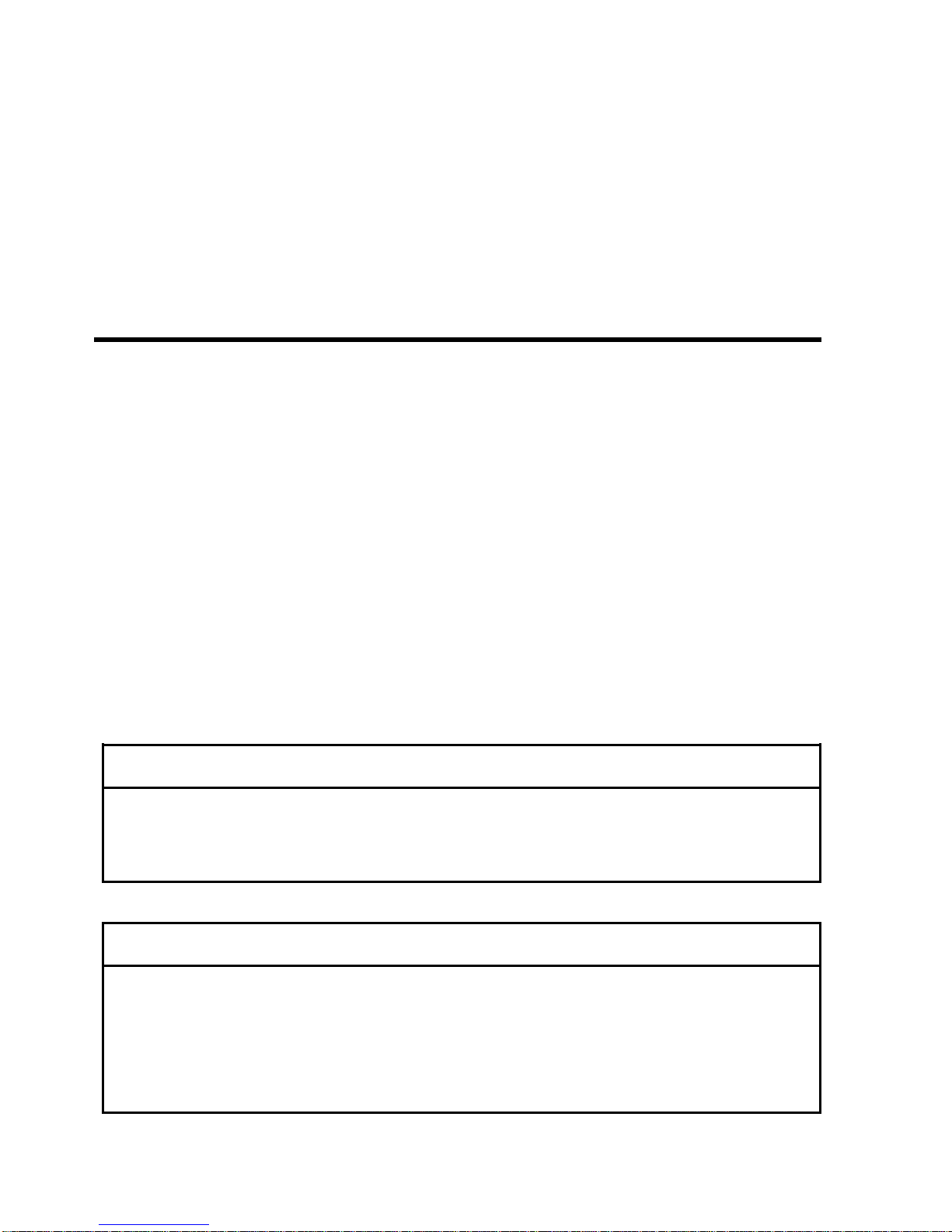
Inflated driver-side air bag
Page 27
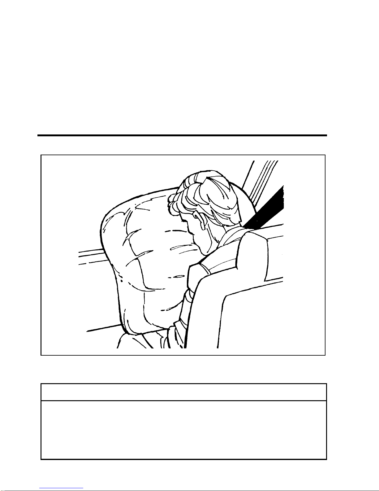
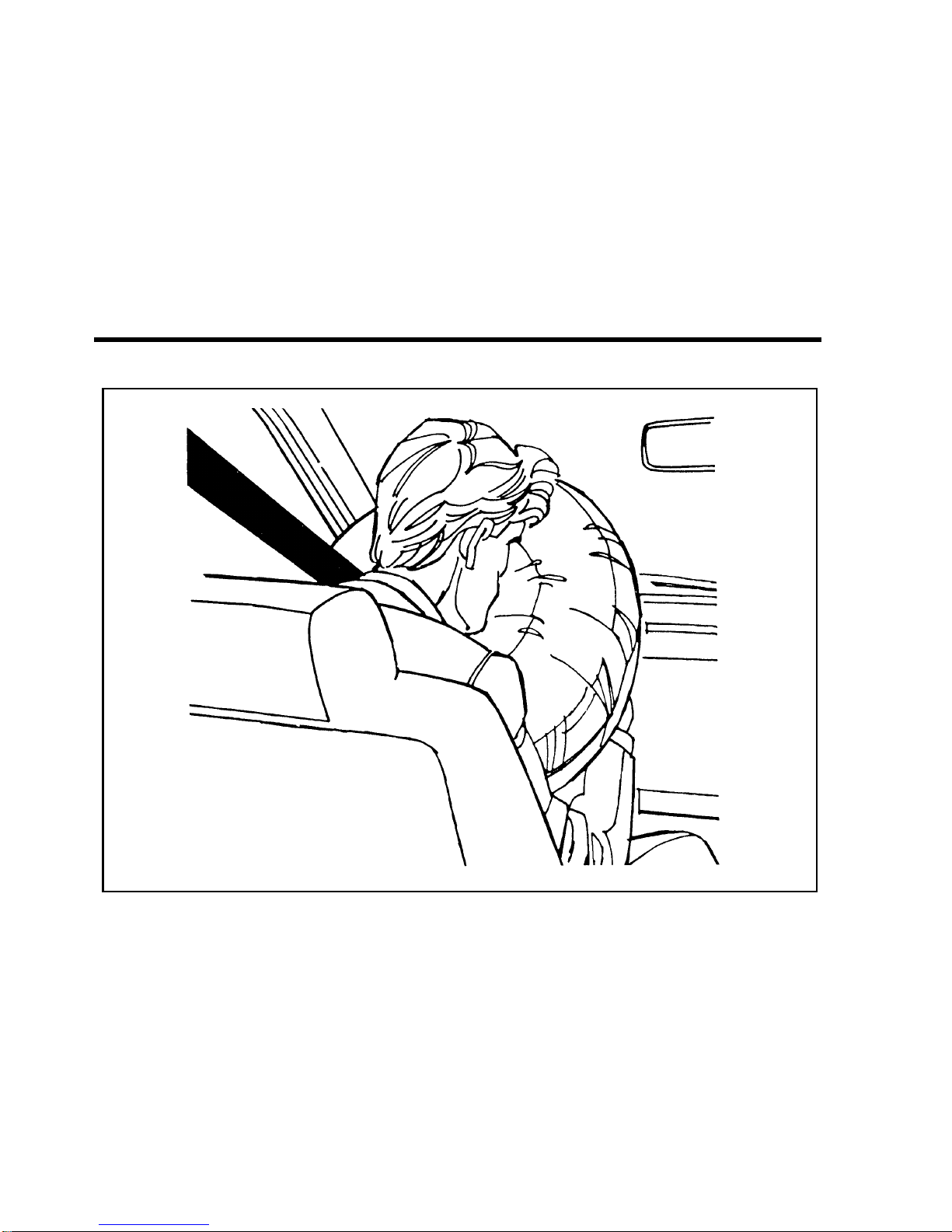
Inflated passenger-side air bag
RWARNING
If the air bag is inflated, THE AIR BAG WILL NOT
FUNCTION AGAIN AND MUST BE REPLACED
IMMEDIATELY. If the air bag is not replaced, the
unrepaired area will increase the risk of injury in a
collision.
To ensure that the air bag system will operate as intended in a
crash, the system is equipped with a diagnostic module, which
Page 28

Safety Restraints
The air bag system uses a readiness light and a tone to indicate
the condition of the system. The readiness light is in the
instrument cluster. When you turn the ignition to the ON
position, this light will illuminate for approximately six (6)
seconds and then turn off. This indicates that the system is
operating normally. NOTE: Maintenance of the air bag system is
not required.
A problem with the system is indicated by one or more of the
following:
■ the readiness light will either flash or stay lit,
■ or it will not light immediately after ignition is turned on,
■ a group of five beeps will be heard. The tone pattern will
repeat periodically until the problem and light are repaired.
If any of these things happen, even intermittently, have the air
bag system serviced at your Ford or Lincoln-Mercury dealer
immediately.
Disposal of supplemental air bag equipped vehicles
For disposal of air bags or air bag equipped vehicles, see your
local Ford or Lincoln-Mercury dealer. Air bags MUST be
disposed of by qualified personnel.
In the U.S. and Canada, you are required by law to use safety
restraints for children. If small children ride in your vehicle —
this generally includes children who are four years old or
younger and who weigh 40 pounds (18 kg) or less — you must
Page 29
RWARNING
Never let a passenger hold a child on his or her lap
while the vehicle is moving. The passenger cannot
protect the child from injury in a collision.
RWARNING
Passengers should not be allowed to ride in the cargo
area. Persons not riding in a seat with a fastened seat
belt are much more likely to suffer serious injury in a
collision. Cargo should always be secured to prevent it
from shifting and causing damage to the vehicle or harm
to passengers.
RWARNING
Carefully follow all of the manufacturer’s instructions
included with the safety seat you put in your vehicle. If
you do not install and use the safety seat properly, the
child may be injured in a sudden stop or collision.
RWARNING
Never leave a child unattended in your vehicle.
RWARNING
Page 30
Safety Restraints
When possible, put children in the rear seat of your vehicle. Accident
statistics suggest that children are safer when properly restrained in the
rear seating positions than in the front seating positions.
Built-In Child Seat (If equipped)
The second row bench seat may include two optional built-in
child safety seats (one on the driver side and one on the
passenger side). This child restraint is to be used only by
children who are at least one year old, weigh between 9 and
27 kilograms (20 and 60 pounds) and whose shoulders (top) are
below the bottom of the headrest in the full up position.
If your child is less than one year old or weighs less than
9 kilograms (20 pounds), always use a rear facing infant or
convertible seat because a child of that size is not sufficiently
developed to withstand crash forces in a front facing position.
Follow the specific manufacturer’s instructions for weight and
height restrictions.
RWARNING
Always latch the vehicle seat to the floor, whether the
seat is occupied or empty. If not latched, the seat may
cause injury during a sudden stop.
Children must be properly buckled before riding in the vehicle.
It is the law in every state and province. This child seat
conforms to all Federal/Canadian motor vehicle safety
standards.
Built-in child seat belt retractors
The belts on the built-in child seat are equipped with a retractor
that locks when both belt tongues are latched into the crotch
safety belt and buckle.
Page 31

The automatic locking mode must be used to hold small
children in position, particularly sleeping children and those
who may try to squirm out of the belts. The emergency locking
mode is also used while buckling the belts.
Frequently check the child seat’s lap and shoulder harness belts
for correct placement and tightness. Use the child seat only if
the harness belts will stay snug when belts are placed into the
lock mode with a child in the seat. If belts do not remain snug,
take the vehicle to the dealer for child seat repair.
Always adjust the lap and shoulder harness belts provided with
this child seat snugly around your child.
RWARNING
Never leave a child unattended in your vehicle.
RWARNING
Safety belts and seats can become hot in a vehicle that
has been closed up in sunny weather; they could burn a
small child. Check seat covers and buckles before you
place a child anywhere near them.
RWARNING
Failure to follow all of the instructions on the use of this
child restraint system can result in your child striking the
vehicle’s interior during a sudden stop or crash.
Page 32

Safety Restraints
How to use the Built-In Child Seat
Read the following procedures and all of the labels on the
Built-In Child Seat before using the seat.
RWARNING
Never use the Built-In Child Seat as a booster cushion
with the adult safety belts. A child using the adult belts
could slide forward and out from under the safety belts.
shown in Figure 1. Then release the lever and rotate the
headrest full up until the latch “clicks” in the full up
position. Refer to Figure 2.
Figure 1: Releasing the headrest
Page 33

Figure 2: Release the lever and rotate the headrest to the full up position
seat will move to a semi-reclined position as the seat cushion
is lowered.
protector flap and shoulder safety belt. Refer to Figure 3.
Check the child’s size, weight and age to be sure the child is
not too small or too large for the child seat. Then fold the
flap down onto the adult seat cushion.
Page 34

Safety Restraints
Figure 3: Child seat information and warnings
half of the chest clip and pull to separate both halves.
Page 35

belts over each shoulder. Refer to Figure 4.
Figure 4: Shoulder safety belt placement on the child
NOTE: Read the following steps carefully to become familiar
with the indicator windows located on each safety belt
tongue and the chest clip. When either of the tongues
or the chest clip is unbuckled, the color red appears in
the window. When the tongues or chest clip are
securely buckled, the color green appears.
Page 36

Safety Restraints
single opening of the crotch safety belt buckle as shown in
Figure 5. (It does not matter which tongue is inserted first.)
Then insert the other tongue. The color green must appear in
the indicator window on each tongue when buckled.
Page 37

shoulders and adjust it to comfortably hold the shoulder
belts in place on the child’s chest. The color green must
appear in the indicator window when fastened. (The purpose
of this clip is to position the shoulder belts correctly on the
child’s shoulders.) Refer to Figure 6.
RWARNING
If both tongues do not latch in the buckle, do not use the
child seat. See your dealer for repairs.
Page 38

Safety Restraints
Figure 6: Securing the chest clip
Page 39

belt buckle and chest clip are securely fastened. Refer to
Figure 7.
Figure 7: Checking for securely latched buckle and chest clip
lock mode. Allow belts to retract and fit snugly. The purpose
of the lock mode is to prevent the child from getting out of
the seat while the vehicle is in operation and to hold a
sleeping child in position. The belts will lock automatically
during a collision or hard braking.
To remove the child from the built-in child seat:
Page 40

Safety Restraints
To fold up the child seat:
back to Figure 3.
downward until it latches against the child seat cushion.
Refer back to Figures 1 and 2.
that an adult may use the vehicle’s rear seat.
Inspection after a collision
RWARNING
All built-in child restraints, including seats, buckles,
retractors, seat latches, interlocks, and attaching hardware
should be inspected by a qualified dealer technician after
any collision.
If the child seat was in use during a collision, Ford recommends
replacing it. However, if the collision was minor and a qualified
tehcnician finds that the child restraints do not show damage
and continue to operate properly, they do not need to be
replaced. If there is any bending of the vehicle seat back or seat
structure, it should also be replaced. Built-in child seats not in
use during a collision should also be inspected and replaced if
either damage or improper operation is noted.
Cleaning
Page 41

Built-in child seat maintenance
Regularly inspect the lap and shoulder belts system of your
child seat. See your Ford Dealer if the shoulder belt webbing is
frayed, or if the buckle and tongue are damaged and/or do not
function properly.
Safety Belts for Children
Children who are too large for child safety seats should always
wear safety belts. (See instructions with your child seat, or
contact its manufacturer, to determine maximum size of child
that will safely fit in the seat.)
RWARNING
If safety belts are not properly worn and adjusted as
described, the risk of serious injury to the child in a
collision will be much greater.
If the shoulder belt portion of one of the lap and shoulder belts
can be positioned so that it does not cross or rest in front of the
child’s face or neck, the child should wear the lap and shoulder
belt. Moving the child closer to the center of the vehicle may
help provide a good shoulder belt fit.
Lap belts and the lap belt portion of lap and shoulder belts
should always be worn snugly and below the hips, touching the
child’s thighs.
RWARNING
Page 42

Safety Restraints
Safety Seats for Children
Use a safety seat that is recommended for the size and weight
of the child. Always follow the safety seat manufacturer’s
instructions when installing and using the safety seat.
Ford recommends the use of a child safety seat having a top
tether strap. Install the child safety seat in a seating position
which is capable of providing a tether anchorage. For more
information on top tether straps see Attaching Safety Seats With
Tether Straps in this chapter.
When installing a child safety seat, be sure to use the correct
safety belt buckle for that seating position, and make sure the
tongue is securely fastened in the buckle.
In rear-facing infant seats, the infant’s head is closer to the
passenger air bag. The force of the rapidly inflating air bag
could push the top of the rear-facing seat against the vehicle
seatback. REAR-FACING INFANT SEATS MUST ALWAYS BE
SECURED IN THE REAR SEAT, and other child seats and
infant seats should be secured in the rear seat whenever
possible. Forward-facing child seats used in the front seat must
have the passenger seat moved as far back from the instrument
panel as possible.
Your vehicle is equipped with a right front passenger air bag.
Air bags deploy with great force, faster than the blink of an eye.
Front passengers, especially children and small adults, must
never sit on the front edge of the seat, stand near the glove
compartment of the instrument panel, or lean over near the air
bag cover when the vehicle is moving. All occupants should sit
with their backs against the seatback, move the seat to the most
Page 43

RWARNING
When using forward-facing child seats move the
passenger seat as far back from the instrument panel as
possible. NEVER SECURE REAR-FACING INFANT
SEATS IN THE FRONT SEAT.
THE FORCE OF THE RAPIDLY INFLATING PASSENGER AIR
BAG COULD PUSH THE TOP OF THE REAR-FACING SEAT
AGAINST THE VEHICLE SEATBACK, ARMRESTS OR
CONSOLE. REAR-FACING INFANT SEATS MUST ALWAYS
BE SECURED IN THE REAR SEAT.
All child restraint systems are designed to be secured in vehicle
seats by lap belts or by the lap portion of a lap-shoulder belt.
RWARNING
If you do not properly secure the safety seat, the child
occupying the seat may be injured during a collision or
sudden stop. An unsecured safety seat could also injure
other passengers.
RWARNING
Carefully follow all of the manufacturer’s instructions
included with the safety seat you put in your vehicle. If
you do not install and use the safety seat properly, the
child may be injured in a sudden stop or collision.
Page 44

Safety Restraints
RWARNING
Always keep the buckle release button pointing upward
and away from the child seat, with the tongue between
the child seat and the release button as shown in the
following illustration.
Seat and Rear Window Passenger Seating
Positions
Your vehicle is equipped with a dual locking mode retractor on
the shoulder belt portion of the combination lap/shoulder safety
belt for the front seat passenger and for the rear window
passengers.
If you choose to install a forward-facing child seat or infant
carrier in the front seating positions, move the seat as far back
as possible.
Page 45

For seating positions equipped with a dual-locking mode
retractor, use the following procedure:
belt together. Figure 1.
Page 46

Safety Restraints
route the tongue through the child seat according to the
child seat manufacturer’s instructions. See Figure 2. Be sure
that the belt webbing is not twisted.
Routing the lap/shoulder belt
Page 47

until you hear and feel the latch engage. See Figure 3. Make
sure the tongue is latched securely to buckle by pulling on
the tongue.
Buckling the belt
until all of the belt is extracted and a click is heard. At this
time, the retractor is in the automatic locking mode (child
restraint mode). See Figure 4.
NOTE: The dual-locking mode retractor must be in the
Page 48

Safety Restraints
Setting the retractor to automatic locking mode
the belt retracts. This indicates the retractor is in the
automatic locking mode. Pull on the lap belt portion across
the child seat towards the buckle and continue to pull up on
the shoulder belt portion while pushing down on the child
seat allowing the shoulder belt to retract, to remove any
slack in seat belt. See Figures 5 and 6.
Page 49

Page 50

Safety Restraints
Page 51

seat from side to side and in forward directions to make
sure that the seat is securely held in place. See Figure 7.
Checking that the seat is secure
Try to pull more belt out of the retractor. If you cannot, the
belt is in the automatic locking mode. See Figure 8.
Page 52

Safety Restraints
Checking the retractor
each use. If the retractor is not locked, repeat steps 6
through 8.
NOTE: To remove retractor from the automatic lock mode,
allow seat belt to retract fully to its stowed position
and the retractor will automatically switch back to the
vehicle sensitive locking mode for normal adult usage.
Installing a Child Safety Seat at the Rear Center
Seating Position with Locking Adjustable Lap Belt
Page 53

according to the child seat manufacturer’s instructions.
seating position until you hear a snap and feel it latch. Make
sure the tongue is securely fastened to the buckle by pulling
on tongue.
of the lap belt webbing to tighten the belt.
child seat from side to side and in forward directions to
ensure that the seat is held securely in place. If the child seat
moves excessively, repeat steps 5 through 6 or properly
install the child seat in a different seating position.
Attaching Safety Seats With Tether Straps
Some manufacturers make safety seats that include a tether
strap that goes over the back of the vehicle seat and attaches to
an anchoring point. Other manufacturers offer the tether strap
as an accessory. Contact the manufacturer of your child safety
seat for information about ordering a tether strap.
You can attach a tether strap to the front passenger or second
row seats by using the built-in tether anchors provided on the
back of the seats as described below.
Follow the child seat manufacturer’s instructions to attach the
tether strap to the tether anchor.
Page 54

Safety Restraints
Three tether strap anchor locations have been provided in your
vehicle. They are as follows:
Tether strap anchor locations
■ FRONT PASSENGER SEATING POSITION — You must use
Page 55

Figure 1: Tether anchor location — Front passenger seat
■ SECOND ROW BENCH (if equipped) SEATING POSITION
— You must use one of the two tether strap anchor locations
(one each side) provided on the back of the seat cushion.
(Refer to Figures 2 and 3.)
Page 56

Safety Restraints
Figure 3: Tether anchor location — second row bench seat (without built-in
child safety seat)
■ SECOND ROW BUCKET (if equipped) SEATING POSITION
— You must use the tether strap anchor location provided
on the back of the seat cushion. (Refer to Figure 4.)
Page 57

Figure 4: Tether anchor location — second row bucket seat
RWARNING
Only use the tether attachment hole locations shown in
the illustrations. The tether anchor may not perform
properly if the wrong mounting location is used.
Once you have attached the safety seat, test the seat before you
place the child in it. Tilt the seat from side to side. Also try to
tug the seat forward. Check to see if the belt holds the seat in
place.
RWARNING
If the safety seat is not anchored properly, the risk of a
Page 58

Starting Your Windstar
Understanding the Positions of the Ignition
The ignition positions
ACCESSORY allows you to operate some of your vehicle’s
electrical accessories while the engine is not running. For
example, you can use ACCESSORY to turn on the radio or
windshield wipers without starting the engine.
LOCK locks the steering wheel and the gearshift lever.
OFF allows you to shut off the engine and all accessories
without locking the steering wheel, or the gearshift lever.
ON allows you to test your vehicle’s warning lights to make
sure they work before you start the engine. The key returns to
the ON position once the engine is started and remains in this
Page 59

Removing the Key From the Ignition
LOCK is the only position that allows you to remove the key
from the ignition. The LOCK feature helps to protect your
vehicle from theft, because it also locks the steering wheel and
the gearshift lever when the key is removed.
If your key is stuck in the LOCK position, and you are unable
to turn it, move your steering wheel left or right until the key
turns freely.
To remove your key from the ignition:
RWARNING
When you leave your vehicle, place the gearshift lever in
Park (P). Set the parking brake fully, and shut off the
engine. Never park your vehicle in Neutral (N). If you do
not take these precautions, your vehicle may move
suddenly and injure someone.
RWARNING
Do not leave children, unreliable adults, or pets alone in
your vehicle. They could accidentally injure themselves
or others through inadvertent operation of the vehicle.
Page 60

Starting Your Windstar
Since your vehicle has a fuel-injected engine, the most
important thing to remember is to avoid pressing down on the
accelerator while cranking the engine to start. Only use the
accelerator when you have problems getting your vehicle
started. See Starting a Cold Engine and Starting a Warm Engine
later in this chapter for details about when to use the
accelerator while you start your vehicle.
Preparing to Start Your Vehicle
RWARNING
Do not start your vehicle in a closed garage or in other
enclosed areas. Exhaust fumes can be toxic. Always open
the garage door before you start the engine. See
Guarding Against Exhaust Fumes in this chapter for more
instructions.
Before you start your vehicle, always:
belts. See Safety belts in the Index for more details.
off when starting.
parking brake is set before you turn the key.
Before you start your vehicle, you should test the warning lights
on the instrument cluster to make sure that they work. Refer to
the Warning Lights and Gauges chapter.
Page 61

Starting the Engine
To start the engine:
under Testing the Warning Lights in this section.
to ON.
engine. DO NOT use the accelerator until after the engine is
running and you are ready to drive away.
(Release the key after the engine has started and it will
return to the ON position.)
If you have difficulty in turning the key, rotate the steering
wheel slightly to relieve any binding.
For a cold engine:
■ At temperatures 10˚F (-12˚C) and below: If the engine does
not start in fifteen (15) seconds on the first try, turn the key
to OFF, wait approximately ten (10) seconds so you do not
flood the engine, then try again.
■ At temperatures above 10˚F (-12˚C): If the engine does not
start in five (5) seconds on the first try, turn the key to OFF,
wait approximately ten (10) seconds so you do not flood the
engine, then try again.
For a warm engine:
■ Do not hold the key in the START position for more than
Page 62

Starting Your Windstar
Whenever you start your vehicle, release the key as soon as the
engine starts. Excessive cranking could damage the starter or
flood the engine.
After you start the engine, let it idle for a few seconds. Keep
your foot on the brake pedal and release the parking brake.
Put the gearshift lever in gear, slowly release the brake pedal
and drive away in the normal manner.
NOTE: Your vehicle has an interlock that prevents you from
shifting out of P (Park) unless your foot is on the
brake pedal.
If the engine still does not start after two attempts:
minutes.
Then drive away in the normal manner.
If the engine still does not start, the fuel pump shut-off switch
may have been triggered. For directions on how to reset the
switch see Fuel Pump Shut-Off Switch later in this chapter.
A computer system controls the engine’s idle rpm. When you
start your vehicle, the engine’s idling rpm normally runs high.
These faster engine speeds will make your vehicle move slightly
faster than when the engine is at its normal warm engine idle
speed. It should, however, slow down when the vehicle warms
Page 63

RWARNING
Do not park, idle, or drive your vehicle in dry grass or
other dry ground cover. The emission system heats up
the engine compartment and exhaust system, which can
start a fire.
Using the Engine Block Heater (If equipped)
(Standard in Canada)
Using your engine block heater is strongly recommended if you
live in a region where temperatures consistently reach s20˚F
(s29˚C) or below during the winter months. An engine block
heater warms the engine coolant which improves starting,
warms up the engine faster, and allows the heater-defrost
system to respond more quickly.
RWARNING
To prevent electrical shock, do not use your heater with
ungrounded electrical systems or two-pronged (cheater)
adapters.
For best results, plug the heater in at least three hours before
you start your vehicle. Using the heater for longer than three
hours will not damage the engine, so you can leave it plugged
in all night to start your vehicle the following morning.
Page 64

Starting Your Windstar
Fuel Pump Shut-Off Switch
If the engine cranks but does not start or does not start after a
collision, the fuel pump shut-off switch may have been
triggered. The shut-off switch is a device intended to stop the
fuel pump when your vehicle has been involved in a substantial
jolt.
Once the shut-off switch is triggered, you must reset the switch
by hand before you can start your vehicle.
The fuel pump shut-off switch reset button is located behind the
jack access cover under the jack in the cargo compartment.
Fuel pump shut-off switch reset button location
RWARNING
If you see or smell fuel, do not reset the switch or try to
Page 65

If your engine cranks, but does not start after a collision:
reset button down. If the red button is already set, you may
have a different mechanical or electrical problem.
then turn it to the OFF position.
smell fuel, do not start your vehicle again. If there is no fuel,
you can try to start your vehicle again.
Guarding Against Exhaust Fumes
Carbon monoxide, although colorless and odorless, is present in
exhaust fumes.
RWARNING
Never let your vehicle idle in an enclosed area, and do
not sit in a parked vehicle, (with the engine running) for
more than a short period of time. Exhaust fumes,
particularly carbon monoxide, might build up. These
fumes are harmful and could kill you.
RWARNING
Page 66

Starting Your Windstar
Have the exhaust and body ventilation systems checked by a
qualified technician whenever:
■ your vehicle is raised for service
■ the sound of the exhaust system changes
■ your vehicle has been damaged in an accident
If the exhaust system has any indications of leaks it should be
repaired immediately.
Improve your ventilation by keeping all air intake vents clear of
snow, leaves, and other objects.
If the engine idles while you are stopped in an open area for
long periods of time, open the windows at least one inch. Also,
adjust the heating or air conditioning to bring in outside air.
Read the section Climate Control Systems for instructions on
bringing fresh outside air into your vehicle. Refer to the Index.
Page 67

Warning Lights and Gauges
The instrument panel (dashboard) on your vehicle is divided
into several different sections. The illustrations on the following
pages show the major parts of the instrument panel that are
described in this chapter. Some items shown may not be on all
vehicles.
Your vehicle has one of the following clusters:
■ Mechanical Cluster
■ Mechanical Cluster with a tachometer
■ Electronic Cluster
If you are not sure which cluster your vehicle has, check the
diagrams on the following pages.
Page 68

[LG00401(ALL)04/95]
33-1/2 pica
File:wnlgs.ex
Update:Tue Mar 19 08:25:03 1996
Page 69

[LG00450(ALL)04/95]
33-1/2 pica art:0050127-F
File:wnlgs.ex
Update:Tue Mar 19 08:25:03 1996
Page 70

The following warning lights and gauges are on the Mechanical
Cluster. All of these indicators alert you to the status of vehicle
systems or possible problems with your vehicle. Some of the
lights listed are optional. The following section explains each of
the indicators.
Brake System Light
The warning light for the brakes indicates two things — that
either the parking brake is on or not fully released, or that the
brake fluid level is low in the master cylinder reservoir. If the
fluid level is low, the brake system should be checked by a
qualified service technician.
The brake system light
The BRAKE light normally comes on when you turn the
ignition key to the ON or START position to verify that the
indicator bulb is working. If the light stays on or comes on
when the engine is running and after you have released the
parking brake fully, have the hydraulic brake system serviced.
Page 71

Warning Lights and Gauges
Anti-lock Brake System (ABS) Warning Light
To check the anti-lock brake warning light, turn the ignition key
to the ON position. The ABS warning light should glow
momentarily.
NOTE: If it does not glow at all or stays on for a long time,
have your vehicle’s electrical system checked
immediately.
The anti-lock brake warning light
RWARNING
If the anti-lock brake system warning light remains on or
comes on while driving, have the braking system checked
by a qualified service technician as soon as possible.
NOTE: If a fault occurs in the anti-lock system, and the brake
warning light is not lit, the anti-lock system is
disabled but normal brake function remains
operational.
Safety Belt Warning Light and Chime
This warning light and chime remind you to fasten your safety
belt. The following conditions will take place:
Page 72

■ If the driver fastens the safety belt before the ignition is
turned to ON, the chime will not sound and the light will
not illuminate.
■ If the safety belt is buckled while the light is on and the
chime is sounding, both the light and the chime turn off.
The safety belt warning light
Check Engine Warning Light
The Powertrain On-Board Diagnostic II (OBD II) system consists
of the hardware and software necessary to monitor the
operation of the powertrain. The OBD II system is designed to
check the function of the vehicle’s powertrain control system
during normal operation. If an emission problem is detected, the
Check Engine Warning Light (in the cluster) is turned on.
The check engine warning light
Modification or additions to the vehicle may cause incorrect
Page 73

Warning Lights and Gauges
The light comes on briefly when you turn the ignition key to
ON, but it should turn off when the engine starts. If the light
does not come on when you turn the ignition to ON or if it
comes on and stays on when you are driving, have your vehicle
serviced as soon as possible. This indicates a possible problem
with one of the vehicle’s emission control systems. You do not
need to have your vehicle towed in.
If the light turns on and off at one (1) second intervals while
you are driving the vehicle, it means that the engine is
misfiring. If this condition persists, damage could occur to the
engine or catalytic convertor. Have your vehicle serviced at the
first opportunity. You do not need to have your vehicle towed
in.
If the light turns on and off on rare occasions while you are
driving, it means that a malfunction occurred and the condition
corrected itself.
An example of a condition which corrects itself occurs when an
engine running out of fuel begins to misfire. In this case, the
Check Engine Warning Light may turn on and will then set a
Diagnostic Trouble Code indicating that the engine was
misfiring while the last of the fuel was being consumed. After
refueling, the Check Engine Warning Light will turn off after
the vehicle has completed three consecutive warm up cycles
without a misfire condition occurring. A warm up cycle consists
of engine start from a cold condition (engine at ambient
temperature) and running until the engine reaches normal
operating temperature.
On the fourth engine start up, the Check Engine Warning Light
will turn off as soon as the engine begins to crank. It is not
Page 74

Under certain conditions, the Check Engine Warning Light may
come on if the fuel cap is not properly installed. If the Check
Engine Warning Light comes on and you suspect that the fuel
cap is not properly installed, pull off the road as soon as it is
safely possible and turn off the engine. Remove and replace the
cap, making sure it is properly seated.
After completing the three consecutive warm up cycles and on
the fourth engine start up, the Check Engine Warning Light
should turn off. If the light does not go off after the fourth
engine re-start, have your vehicle serviced by your dealer or a
qualified technician.
Charging System Light
This light indicates that your battery is not being charged. The
light comes on briefly during the display self-test every time
you turn your ignition key to the ON position. The light will go
off when the key is turned to the START position. The light
should stay off when the self-test is done if the engine is
running and the alternator is charging.
If the light stays on or comes on when the engine is running,
have the electrical system checked as soon as possible.
The charging system light
Page 75

Warning Lights and Gauges
Oil Pressure Light
The oil pressure light
This light indicates the engine’s oil pressure, not the oil level.
However, if your engine’s oil level is low, it could affect the oil
pressure. The light should come on every time your ignition key
is turned to ON or START, and should go out when the engine
starts. If the light stays on or turns on while the engine is
running, you have lost oil pressure and continued operation will
cause severe engine damage.
If you lose engine oil pressure:
engine as soon as safely possible, severe engine damage
could result.
Engine Oil” in the Servicing Your Vehicle chapter of this
Owner Guide.) If you do not follow these instructions, you
or others could be injured. To ensure an accurate reading,
your vehicle should be on level ground.
you start the engine again. Do not overfill. Do not operate
Page 76

Door Ajar Warning Light
If the ignition switch is in the ON position and any door or the
liftgate is not completely closed, the light will illuminate.
If the light illuminates, safely stop the vehicle and check and
close all doors until the light turns off.
The door ajar warning light
Air Bag Readiness Light
This light indicates that the Air Bag system is not functional
and needs to be serviced. The light illuminates for
approximately six seconds when the ignition is turned to the
ON position to verify that the indicator bulb is working. If the
light fails to illuminate, flashes continuously, or remains on,
have the air bag system serviced as soon as possible.
The air bag readiness light
Page 77

Warning Lights and Gauges
Turn Signal Indicator Lights
See “Turn Signals” in the Steering Column Controls chapter of
this Owner Guide.
The turn signal indicator lights
If one or both of your turn signal indicators does not light up
or remains on continuously when you signal a turn, have the
turn signaling system serviced as soon as possible.
High Beam Light
This light comes on when the headlamps are turned to high
beam or when the high beams are flashed. If your vehicle is
equipped with Daytime Running Lights (Canadian vehicles
only) and the headlamps are on when the high beams are
flashed, the high beam indicator will not light.
The high beam indicator light
Page 78

Low Windshield Washer Fluid Level Warning
(Optional Chime with Light)
This light indicates that the level of your washer fluid is low,
and you have to add more fluid. This light comes on briefly
after you turn your ignition key from the START to the ON
position. If the washer fluid is low, a one second chime will
sound and the light will remain on for 60 seconds. If the washer
fluid is not low, the light should turn off a few seconds after
the engine has started. The light and chime also come on if the
washer fluid is low when you use your windshield washers.
The washer fluid is only checked when the engine is started or
the windshield washers are in operation. The light will not
come on if the fluid level becomes low while you are driving
unless you turn on the windshield washers.
The low windshield washer indicator light
Low Fuel Indicator Light
This light comes on when your fuel gauge indicates
approximately 1/16 of a tank. The ignition must be turned to
ON in order for this light to come on.
Page 79

Warning Lights and Gauges
Fuel Gauge
The fuel gauge displays approximately how much fuel is in the
fuel tank only when the ignition is ON. For proper fuel gauge
indication after adding fuel, the ignition should be in the OFF
position while the vehicle is being refueled.
The fuel gauge indicator may also vary slightly when the
vehicle is in motion. With the ignition OFF, the fuel gauge
indicator may drift from the ignition ON position as well.
Fuel gauge — base cluster
Page 80

The engine coolant temperature and fuel gauge
Engine Coolant Temperature Gauge
This gauge indicates the temperature of the engine coolant, not
the coolant level. If the coolant is not at its proper level or
mixture, the gauge indication will not be accurate.
Engine coolant temperature gauge — base cluster
Page 81

Warning Lights and Gauges
The pointer moves from the C (cold) mark into the NORMAL
band as the engine coolant warms up. It is acceptable for the
pointer to fluctuate within the normal band under normal
driving conditions. Under certain driving conditions such as
heavy stop and go traffic, or driving up hills in hot weather, the
pointer may indicate at the top of the NORMAL band. This is
also acceptable.
If, under any circumstances, the pointer moves above the
NORMAL band, the engine coolant is overheating and
continued operation may cause engine damage.
If your engine coolant overheats:
safely possible, severe engine damage could result.
SYSTEM FILL CAP UNTIL THE ENGINE IS COOL.
checking and adding coolant to your engine in this Owner
Guide. See engine coolant in the index. If you do not follow
these instructions, you or others could be injured.
If the coolant continues to overheat, have the coolant system
serviced.
Speedometer
The speedometer tells you how many miles (kilometers) per
hour your vehicle is moving.
Odometer
Page 82

Trip Odometer
The trip odometer records the distance of individual trips.
Before each trip, set the trip odometer to zero by pushing the
reset button.
The speedometer, odometer and trip odometer
Tachometer (If equipped)
The tachometer will show you the engine’s speed measured in
revolutions per minute (RPM).
The tachometer may move slightly when the key is placed in
the ACC or ON position, with the engine off. This is normal
and does not affect the performance of the tachometer when the
engine is running.
Some vehicles are equipped with an engine speed (RPM)
limiting device that is contained within the Electronic Engine
Control Module. The purpose of this device is to maintain peak
engine speed (RPM) below a specified limit. (Engine speed
Page 83

Warning Lights and Gauges
If you are experiencing an “engine cut-out” condition at high
speeds, it may be the result of this limiting device. It is a
normal condition and can be avoided by reducing
vehicle/engine speed.
The tachometer
Page 84

[LG09570(ALL)04/95]
33-1/2 pica art:0050076-E
File:wnlgs.ex
Update:Tue Mar 19 08:25:03 1996
Page 85

Warning Lights and Gauges
Electronic Cluster (If Equipped)
The Electronic Cluster works only when your ignition is in the
ON position. Each time you start your vehicle, the displays go
through a self-test by lighting up all segments for about one
second and then turning off all segments for about one second,
before displaying actual gauge readings. (The turn signal and
high beam indicators do not light during the self-test. The LOW
OIL light may remain on throughout the self-test and for several
seconds after normal readings are displayed.) This self-test
demonstrates that all of the display segments are working
properly.
The electronic cluster has three major functions to provide you
with information about your vehicle’s operating status:
■ Warning and Indicator Lights
■ Electronic Gauges
■ The Fuel Computer
Safety Belt Warning Light and Chime
This warning light and chime remind you to fasten your safety
belt. The following conditions will take place:
■ If the driver does not fasten the safety belt before the
ignition is turned to ON, the chime will sound for four (4) to
eight (8) seconds and the light will illuminate for one (1) to
two (2) minutes, or until the safety belt is fastened.
■ If the driver fastens the safety belt before the ignition is
turned to ON, the chime will not sound and the light will
Page 86

The safety belt warning light
Brake System Light
The warning light for the brakes indicates two things — that
either the parking brake is on or not fully released, or that the
brake fluid level is low in the master cylinder reservoir. If the
fluid level is low, the brake system should be checked by a
qualified service technician.
The brake system light
The BRAKE light normally comes on when you turn the
ignition key to the ON or START position to verify that the
indicator bulb is working. If the light stays on or comes on
when the engine is running and after you have released the
parking brake fully, have the hydraulic brake system serviced.
RWARNING
Page 87

Warning Lights and Gauges
Air Bag Readiness Light
This light indicates that the Air Bag system is not functional
and needs to be serviced. The light illuminates for
approximately six seconds when the ignition is turned to the
ON position to verify that the indicator bulb is working. If the
light fails to illuminate, flashes continuously, or remains on,
have the air bag system serviced as soon as possible.
The air bag readiness light
Charging System Light
This light indicates that your battery is not being charged. The
light comes on briefly during the display self-test every time
you turn your ignition key to the ON position. The light will go
off when the key is turned to the START position. The light
should stay off when the self-test is done if the engine is
running and the alternator is charging.
If the light stays on or comes on when the engine is running,
have the electrical system checked as soon as possible.
Page 88

Check Engine Warning Light
The Powertrain On-Board Diagnostic II (OBD II) system consists
of the hardware and software necessary to monitor the
operation of the powetrain. The OBD II system is designed to
check the function of the vehicle’s powertrain control system
during normal operation. If an emission problem is detected, the
Check Engine Warning Light (in the cluster) is turned on.
The check engine warning light
Modification or additions to the vehicle may cause incorrect
operation of the OBD II system. Additions such as burglar
alarms, cellular phones, and CB radios must be carefully
installed. Do not install these devices by tapping into or running
wires close to powertrain control system wires or components.
The light comes on briefly when you turn the ignition key to
ON, but it should turn off when the engine starts. If the light
does not come on when you turn the ignition to ON or if it
comes on and stays on when you are driving, have your vehicle
serviced as soon as possible. This indicates a possible problem
with one of the vehicle’s emission control systems. You do not
need to have your vehicle towed in.
If the light turns on and off at one (1) second intervals while
Page 89

Warning Lights and Gauges
If the light turns on and off on rare occasions while you are
driving, it means that a malfunction occurred and the condition
corrected itself.
An example of a condition which corrects itself occurs when an
engine running out of fuel begins to misfire. In this case, the
Check Engine Warning Light may turn on and will then set a
Diagnostic Trouble Code indicating that the engine was
misfiring while the last of the fuel was being consumed. After
refueling, the Check Engine Warning Light will turn off after
the vehicle has completed three consecutive warm up cycles
without a misfire condition occurring. A warm up cycle consists
of engine start from a cold condition (engine at ambient
temperature) and running until the engine reaches normal
operating temperature.
On the fourth engine start up, the Check Engine Warning Light
will turn off as soon as the engine begins to crank. It is not
necessary to have the engine serviced.
Under certain conditions, the Check Engine Warning Light may
come on if the fuel cap is not properly installed. If the Check
Engine Warning Light comes on and you suspect that the fuel
cap is not properly installed, pull off the road as soon as it is
safely possible and turn off the engine. Remove and replace the
fuel cap, making sure it is properly seated.
After completing three (3) consecutive warm up cycles and on
the fourth engine start up, the Check Engine Warning Light
should turn off. If the light does not go off after the fourth
engine re-start, have your vehicle serviced by your dealer or a
qualified technician.
Page 90

Anti-lock Brake System (ABS) Warning Light
To check the anti-lock brake warning light, turn the ignition key
to the ON position. The ABS warning light should glow
momentarily.
NOTE: If it does not glow at all or stays on for a long time,
have your vehicle’s electrical system checked
immediately.
The anti-lock brake warning light
RWARNING
If the anti-lock brake system warning light remains on or
comes on while driving, have the braking system checked
by a qualified service technician as soon as possible.
NOTE: If a fault occurs in the anti-lock system, and the brake
warning light is not lit, the anti-lock system is
disabled but normal brake function remains
operational.
Page 91

Warning Lights and Gauges
Oil Pressure Light
The oil pressure light
This light indicates the engine’s oil pressure, not the oil level.
However, if your engine’s oil level is low, it could affect the oil
pressure. The light will come on briefly during the display
self-test every time you turn your key to the ON position. The
light will go off when the key is turned to the START position.
The light should stay off when the self-test is done if the engine
is running with normal oil pressure. If the light comes on while
the engine is running, you have lost oil pressure and continued
operation will cause severe engine damage.
If you lose engine oil pressure:
engine as soon as safely possible, severe engine damage
could result.
Engine Oil” in the Servicing Your Vehicle chapter of this
Owner Guide.) If you do not follow these instructions, you
or others could be injured. To ensure an accurate reading,
your vehicle should be on level ground.
Page 92

Door Ajar Warning Light
If the ignition switch is in the ON position and any door or the
liftgate is not completely closed, the light will illuminate.
If the light illuminates, safely stop the vehicle and check and
close all doors until the light turns off.
The door ajar warning light
High Beam Light
This light comes on when the headlamps are turned to high
beam or when the high beams are flashed. If your vehicle is
equipped with Daytime Running Lights (Canadian vehicles
only) and the headlamps are on when the high beams are
flashed, the high beam indicator will not light.
The high beam indicator light
Page 93

Warning Lights and Gauges
Low Windshield Washer Fluid Level Warning Light
This light indicates that the level of your washer fluid is low,
and you have to add more fluid. This light comes on briefly
after you turn your ignition key from the START to the ON
position. If the washer fluid is low, a one second chime will
sound and the light will remain on for 60 seconds. If the washer
fluid is not low, the light should turn off a few seconds after
the engine has started. The light and chime also come on if the
washer fluid is low when you use your windshield washers.
The washer fluid is only checked when the engine is started or
the windshield washers are in operation. The light will not
come on if the fluid level becomes low while you are driving
unless you turn on the windshield washers.
The low windshield washer indicator light
Speed Control Indicator
A SPEED CONTROL light is displayed in the optional electronic
instrument cluster when the speed control system is engaged.
The display will turn off when the brake pedal is pressed or if
speed control is shut off.
This display does not indicate any problems with the speed
Page 94

The speed control light
Turn Signal Indicator Lights
See “Turn Signals” in the Steering Column Controls chapter of
this Owner Guide.
The turn signal indicator lights
If one or both of your turn signal indicators does not light up
or remains on continuously when you signal a turn, have the
turn signaling system serviced as soon as possible.
Page 95

Warning Lights and Gauges
Hazard Flasher Indicator Light
This light flashes when you turn on the hazard flashers. If your
ignition is ON, the turn signal indicator lights in the electronic
cluster will flash in time with the hazard flashers.
Engine Coolant Temperature Gauge
Engine coolant temperature gauge
This gauge indicates the temperature of the engine’s coolant, not
the coolant level. If the coolant is not at its proper level or
mixture, the gauge indication will not be accurate. The gauge is
identified by a thermometer symbol, an “H” (hot), and a “C”
(cold). The “NORM” indicates the normal operating range. The
Page 96

indicate at the top of the NORMAL band. This is also
acceptable.
If, under any circumstances, the bars move above the NORMAL
band, the temperature symbol will flash and a chime will sound
to alert the driver that the engine coolant is overheating and
continued operation may cause engine damage.
If your engine coolant overheats:
safely possible, severe engine damage could result.
SYSTEM FILL CAP UNTIL THE ENGINE IS COOL.
checking and adding coolant to your engine in this Owner
Guide. See engine coolant in the index. If you do not follow
these instructions, you or others could be injured.
If the coolant continues to overheat, have the coolant system
serviced.
If the temperature gauge displays only the top two and bottom
two bars, the temperature indication system is indicating that it
requires servicing. Take the vehicle to a dealership for service as
soon as possible.
Fuel Gauge
The fuel gauge displays approximately how much fuel you have
in the fuel tank. The number of bars illuminated in the display
Page 97

Warning Lights and Gauges
If the fuel gauge displays only the top two bars and bottom two
bars, or if the Distance to Empty function in the fuel computer
displays CO or CS, you must have the fuel indication system
serviced.
Turn your ignition to OFF while fueling to obtain an accurate
fuel gauge indication. If you do not turn your ignition off, the
fuel gauge will not display the new fuel level immediately, but
will slowly increase to the correct value.
The fuel gauge
Speedometer
The electronic speedometer in the left center of the cluster has
two displays that indicate how fast your vehicle is moving in
miles or kilometers per hour. Press the fuel computer E/M
(English/Metric) button to switch between MPH and km/h. The
main digital speedometer indicates speed up to 120 MPH
(199 km/h). The secondary bar graph speedometer indicates
approximate speed up to 120 MPH in steps of 4 MPH
(180 km/h in steps of 6 km/h). The bar graph speedometer
shows your approximate speed relative to the full scale, and it
gives you a visual indication of how fast your speed is changing
when you accelerate or decelerate.
Page 98

The speedometer and odometer
Odometer
The odometer displays the total number of miles or kilometers
your vehicle has been driven. Press the fuel computer E/M
(English/Metric) button to switch between miles and kilometers.
If the electronic cluster is replaced and the mileage on the old
odometer is unknown, the replacement cluster will be set to
zero miles (kilometers), and the circle “S” symbol to the left of
the odometer will be lit to indicate that a service cluster has
been installed. A label showing the estimated mileage will then
be attached to the door pillar. If the actual mileage can be
verified, an authorized service center can program the correct
mileage into the replacement cluster, and the circled “S” will
not be lit.
If the odometer displays the word “Error,” have your vehicle
serviced.
Page 99

Warning Lights and Gauges
Tachometer
The electronic bar graph tachometer in the right center of the
cluster displays the approximate engine speed in revolutions per
minute (RPM). Each bar on the display represents 200 RPM.
The tachometer
The Electronic Cluster Fuel Computer display is located under
the tachometer and consists of a menu and a digital display.
The fuel computer can display five different functions. They are:
■ Trip distance
■ Instantaneous fuel economy
■ Average fuel economy
■ Distance to empty
Page 100

Fuel Computer Buttons
The fuel computer functions are controlled by the three buttons
located to the right of the electronic cluster:
The fuel computer buttons
SELECT — The SELECT button lets you choose the function
displayed by the fuel computer. Each time you press the
SELECT button, the fuel computer points to the next choice on
the menu. After it reaches the last choice, it returns to the top
of the menu.
E/M — The E/M button lets you switch the fuel computer
functions and the speedometer and odometer displays between
English and metric units. The displays remain in the chosen
units until you switch them again, even after you turn off the
vehicle and restart it.
RESET — The RESET button lets you reset or initialize the fuel
computer function that is displayed. Only TRIP DISTANCE,
AVERAGE ECONOMY, and AVERAGE SPEED can be reset.
Any time one of the fuel computer buttons is pressed, a short
chime will sound.
 Loading...