

Force FX Electrosurgical Generator C Service Manual

Service Manual
TM
Force FX
Electrosurgical Generator C

Preface
This manual and the equipment it describes are for use only by qualified medical
professionals trained in the particular technique and surgical procedure to be performed.
It is intended as a guide for servicing the Force FX Electrosurgical Generator C only.
Additional users information is available in the Force FX Electrosurgical Generator C
User’s Guide.
Equipment covered in this manual:
Covidien Force FX Electrosurgical Generator C
110 V ~ Nominal / 230 V ~ Nominal (auto selected)
The Force FX Electrosurgical Generator C Service Manual consists of two parts: the text
(part 1 of 2) and a Schematics Supplement (part 2 of 2) which contains the schematics.
Device is compliant with the European Communities Council Directive 93/42/EEC,
Medical Device Directive.
Conventions Used in this Guide
Warning
Indicates a potentially hazardous situation which, if not avoided, could result in death or serious
injury.
Caution
Indicates a hazardous situation which, if not avoided, may result in minor or moderate injury.
Notice
Indicates a hazard which may result in product damage.
Important
Indicates an operating tip or maintenance suggestion.
ii Force FX Electrosurgical Generator C Service Manual

Limited Warranty
Covidien warrants each covered product listed below to be free from defects in material
and workmanship for normal use and service for the period(s) set forth below. Covidien’s
obligation under this warranty is limited to the repair or replacement, at its sole option,
of any product, or part thereof, which has been returned to it (or its authorized
distributor) within the applicable time period shown below after delivery of the product
to the original purchaser, and which examination discloses, to Covidien’s satisfaction, that
the product is defective. This limited warranty does not apply to any product, or part
thereof, which has been repaired or altered in a way so as, in Covidien’s judgment, to
affect its stability or reliability, or which has been subjected to misuse, neglect, or
accident.
The warranty periods for Covidien products are as follows:
ForceTriadTM Energy Platform One year from date of shipment
Electrosurgical Generators One year from date of shipment
TM
Cool-tip
EvidentTM MWA Generator One year from date of shipment
RFG-3C
LigaSure
RFA Generator One year from date of shipment
TM
Plus Lesion Generator One year from date of shipment
TM
Vessel Sealing System One year from date of shipment
LigaSureTM Reusable Instruments One year from date of shipment
Mounting Fixtures (all models) One year from date of shipment
Footswitches (all models) One year from date of shipment
TM
Valleylab
RapidVac
LigaSure
Argon Gas Delivery Unit II One year from date of shipment
TM
Smoke Evacuator One year from date of shipment
TM
Sterile Single Use Items Sterility only as stated on packaging
Cool-tipTM Sterile Single Use Items Sterility only as stated on packaging
Sterile Single Use Items Sterility only as stated on packaging
Patient Return Electrodes Shelf life only as stated on packaging
Notwithstanding any other provision herein or in any other document or communication,
Covidien’s liability with respect to this limited warranty and the products sold hereunder
shall be limited to the aggregate purchase price for the products sold to the customer.
This limited warranty is non-transferable and runs only to the original purchaser of the
Force FX Electrosurgical Generator C Service Manual iii

covered product(s). There are no warranties which extend beyond the terms hereof.
Covidien disclaims any liability hereunder or elsewhere in connection with the sale of
products and for any form of indirect, tort, or consequential damages.
This limited warranty and the rights and obligations hereunder shall be construed under
and governed by the laws of the State of Colorado, USA. The sole forum for resolving
disputes arising under or relating in any way to this limited warranty is the District Court
of the County of Boulder, State of Colorado, USA.
Covidien reserves the right to make changes in covered products built or sold by it at any
time without incurring any obligation to make the same or similar changes to equipment
previously built or sold by it.
THE OBLICATION TO REPAIR OR REPLACE A DEFECTIVE OR NONPERFORMING PRODUCT
IS THE SOLE REMEDY OF THE CUSTOMER UNDER THIS LIMITED WARRANTY. EXCEPT AS
EXPRESSLY PROVIDED HEREIN, COVIDIEN DISCLAIMS ALL OTHER WARRANTIES,
WHETHER EXPRESS OR IMPLIED, ORAL OR WRITTEN, WITH RESPECT TO
PRODUCTS, INCLUDING WITHOUT LIMITATION ALL IMPLIED WARRANTIES,
WARRANTIES OF MERCHANTABILITY OR FITNESS FOR A PARTICULAR PURPOSE.
iv Force FX Electrosurgical Generator C Service Manual

Table of Contents
Preface . . . . . . . . . . . . . . . . . . . . . . . . . . . . . . . . . . . . . . . . . . . . . . . ii
Conventions Used in this Guide . . . . . . . . . . . . . . . . . . . . . . . . . . . ii
Limited Warranty . . . . . . . . . . . . . . . . . . . . . . . . . . . . . . . . . . . . . . iii
Chapter 1. Introduction
General Description . . . . . . . . . . . . . . . . . . . . . . . . . . . . . . . . . . . 1-2
List of Components . . . . . . . . . . . . . . . . . . . . . . . . . . . . . . . . . . . 1-2
Service Personnel Safety . . . . . . . . . . . . . . . . . . . . . . . . . . . . . . . 1-3
General. . . . . . . . . . . . . . . . . . . . . . . . . . . . . . . . . . . . . . . . . . 1-3
Active Accessories . . . . . . . . . . . . . . . . . . . . . . . . . . . . . . . . . 1-3
Patient Return Electrodes . . . . . . . . . . . . . . . . . . . . . . . . . . . 1-4
Fire/Explosion Hazards . . . . . . . . . . . . . . . . . . . . . . . . . . . . . 1-4
Electric Shock Hazards. . . . . . . . . . . . . . . . . . . . . . . . . . . . . . 1-4
Servicing . . . . . . . . . . . . . . . . . . . . . . . . . . . . . . . . . . . . . . . . . 1-5
Calibration . . . . . . . . . . . . . . . . . . . . . . . . . . . . . . . . . . . . . . . 1-5
Cleaning . . . . . . . . . . . . . . . . . . . . . . . . . . . . . . . . . . . . . . . . . 1-6
Chapter 2. Controls, Indicators, and Receptacles
Front Panel . . . . . . . . . . . . . . . . . . . . . . . . . . . . . . . . . . . . . . . . . . 2-2
Bipolar Controls . . . . . . . . . . . . . . . . . . . . . . . . . . . . . . . . . . . . . . 2-3
Bipolar Instrument Receptacle . . . . . . . . . . . . . . . . . . . . . . . . . . 2-4
Monopolar Cut Controls . . . . . . . . . . . . . . . . . . . . . . . . . . . . . . . 2-5
Monopolar Coag Controls . . . . . . . . . . . . . . . . . . . . . . . . . . . . . . 2-6
Monopolar Instrument Receptacles . . . . . . . . . . . . . . . . . . . . . . 2-7
REM Alarm Indicator . . . . . . . . . . . . . . . . . . . . . . . . . . . . . . . . . . 2-8
Rear Panel. . . . . . . . . . . . . . . . . . . . . . . . . . . . . . . . . . . . . . . . . . . 2-8
Footswitch Receptacles . . . . . . . . . . . . . . . . . . . . . . . . . . . . . . . . 2-9
Monopolar Footswitch Receptacles . . . . . . . . . . . . . . . . . . . 2-9
Bipolar Footswitch Receptacle . . . . . . . . . . . . . . . . . . . . . . . 2-9
Power Entry Module . . . . . . . . . . . . . . . . . . . . . . . . . . . . . . . . . 2-10
Activation Tone Volume Control . . . . . . . . . . . . . . . . . . . . . . . 2-10
Option Panel . . . . . . . . . . . . . . . . . . . . . . . . . . . . . . . . . . . . . . . 2-11
Chapter 3. Technical Specifications
Performance Characteristics . . . . . . . . . . . . . . . . . . . . . . . . . . . . 3-2
General. . . . . . . . . . . . . . . . . . . . . . . . . . . . . . . . . . . . . . . . . . 3-2
Dimensions and Weight . . . . . . . . . . . . . . . . . . . . . . . . . . . . 3-2
Operating Parameters . . . . . . . . . . . . . . . . . . . . . . . . . . . . . . 3-2
Transport and Storage . . . . . . . . . . . . . . . . . . . . . . . . . . . . . 3-3
Duty Cycle . . . . . . . . . . . . . . . . . . . . . . . . . . . . . . . . . . . . . . . 3-3
Force FX Electrosurgical Generator C Service Manual v

Internal Memory . . . . . . . . . . . . . . . . . . . . . . . . . . . . . . . . . . 3-3
Audio Volume . . . . . . . . . . . . . . . . . . . . . . . . . . . . . . . . . . . . 3-4
REM Contact Quality Monitor. . . . . . . . . . . . . . . . . . . . . . . . 3-4
Serial Port . . . . . . . . . . . . . . . . . . . . . . . . . . . . . . . . . . . . . . . . 3-5
RF Activation Port . . . . . . . . . . . . . . . . . . . . . . . . . . . . . . . . . 3-5
Expansion Port . . . . . . . . . . . . . . . . . . . . . . . . . . . . . . . . . . . . 3-6
Low Frequency (50–60 Hz) Leakage Current . . . . . . . . . . . . 3-6
High Frequency (RF) Leakage Current . . . . . . . . . . . . . . . . . 3-6
Input Power . . . . . . . . . . . . . . . . . . . . . . . . . . . . . . . . . . . . . . 3-7
Power Cord Specification . . . . . . . . . . . . . . . . . . . . . . . . . . . 3-7
Standards and IEC Classifications . . . . . . . . . . . . . . . . . . . . . . . . 3-8
Class I Equipment (IEC 60601-1) . . . . . . . . . . . . . . . . . . . . . . 3-9
Type CF Equipment (IEC 60601-1)/Defibrillator Proof . . . . . 3-9
Liquid Spillage (IEC 60601-2-2 Clause 44.3) . . . . . . . . . . . . . 3-9
Electromagnetic Interference . . . . . . . . . . . . . . . . . . . . . . . . 3-9
Electromagnetic Compatibility (IEC 60601-1-2 and
IEC 60601-2-2) . . . . . . . . . . . . . . . . . . . . . . . . . . . . . . . . . . . . 3-9
Voltage Transients (Emergency Generator Mains
Transfer) . . . . . . . . . . . . . . . . . . . . . . . . . . . . . . . . . . . . . . . . 3-10
Output Characteristics . . . . . . . . . . . . . . . . . . . . . . . . . . . . . . . . 3-14
Maximum Output for Bipolar and Monopolar Modes . . . 3-14
Maximum Output for Ultrasonic Electrosurgery . . . . . . . . 3-15
Available Power Settings in Watts . . . . . . . . . . . . . . . . . . . 3-15
Output Waveforms . . . . . . . . . . . . . . . . . . . . . . . . . . . . . . . 3-17
Output Power vs. Resistance Graphs. . . . . . . . . . . . . . . . . . . . . 3-18
Bipolar Graphs . . . . . . . . . . . . . . . . . . . . . . . . . . . . . . . . . . . 3-18
Monopolar Cut Graphs . . . . . . . . . . . . . . . . . . . . . . . . . . . . 3-25
Monopolar Coag Graphs . . . . . . . . . . . . . . . . . . . . . . . . . . . 3-33
Chapter 4. Principles of Operation
Block Diagram . . . . . . . . . . . . . . . . . . . . . . . . . . . . . . . . . . . . . . . 4-2
Functional Overview . . . . . . . . . . . . . . . . . . . . . . . . . . . . . . . . . . 4-3
Instant Response Technology . . . . . . . . . . . . . . . . . . . . . . . . 4-3
Ultrasonic Electrosurgery . . . . . . . . . . . . . . . . . . . . . . . . . . . 4-3
Simultaneous Coag . . . . . . . . . . . . . . . . . . . . . . . . . . . . . . . . 4-3
REM Contact Quality Monitoring System. . . . . . . . . . . . . . . 4-4
Control Board . . . . . . . . . . . . . . . . . . . . . . . . . . . . . . . . . . . . . . . . 4-6
Microcontrollers . . . . . . . . . . . . . . . . . . . . . . . . . . . . . . . . . . . 4-6
Main Microcontroller. . . . . . . . . . . . . . . . . . . . . . . . . . . . . . . 4-6
Feedback Microcontroller . . . . . . . . . . . . . . . . . . . . . . . . . . . 4-7
Shared RAM . . . . . . . . . . . . . . . . . . . . . . . . . . . . . . . . . . . . . . 4-8
vi Force FX Electrosurgical Generator C Service Manual

I/0 Expansion . . . . . . . . . . . . . . . . . . . . . . . . . . . . . . . . . . . . . 4-8
Keyboard Interface and Activation Inputs. . . . . . . . . . . . . . 4-8
Power Supply Supervisor Circuit . . . . . . . . . . . . . . . . . . . . . . 4-9
A/D and D/A Conversion . . . . . . . . . . . . . . . . . . . . . . . . . . . . 4-9
Waveform Generation (T_ON ASIC) . . . . . . . . . . . . . . . . . . . 4-9
T_ON Average Check. . . . . . . . . . . . . . . . . . . . . . . . . . . . . . 4-10
Audio Alarm. . . . . . . . . . . . . . . . . . . . . . . . . . . . . . . . . . . . . 4-10
Serial Interface. . . . . . . . . . . . . . . . . . . . . . . . . . . . . . . . . . . 4-10
Dosage Error Algorithm . . . . . . . . . . . . . . . . . . . . . . . . . . . 4-11
Instant Response Algorithm . . . . . . . . . . . . . . . . . . . . . . . . 4-12
Front Panel . . . . . . . . . . . . . . . . . . . . . . . . . . . . . . . . . . . . . . . . . 4-13
Membrane Keyboard . . . . . . . . . . . . . . . . . . . . . . . . . . . . . 4-13
Power Switch . . . . . . . . . . . . . . . . . . . . . . . . . . . . . . . . . . . . 4-13
REM Connector/Switch . . . . . . . . . . . . . . . . . . . . . . . . . . . . 4-13
CEM Mechanism Switch . . . . . . . . . . . . . . . . . . . . . . . . . . . 4-13
Display Board . . . . . . . . . . . . . . . . . . . . . . . . . . . . . . . . . . . . . . . 4-14
RF Indicator Lamps . . . . . . . . . . . . . . . . . . . . . . . . . . . . . . . 4-14
REM Indicators . . . . . . . . . . . . . . . . . . . . . . . . . . . . . . . . . . . 4-14
LED and Seven-Segment Display Drivers . . . . . . . . . . . . . . 4-14
CEM Switch Circuit. . . . . . . . . . . . . . . . . . . . . . . . . . . . . . . . 4-15
Mode Selection and Power Control Switches . . . . . . . . . . 4-15
Footswitch Board . . . . . . . . . . . . . . . . . . . . . . . . . . . . . . . . . . . . 4-17
Footswitch Decode Circuit . . . . . . . . . . . . . . . . . . . . . . . . . 4-17
Audio Circuit . . . . . . . . . . . . . . . . . . . . . . . . . . . . . . . . . . . . 4-18
Power Supply/RF Board . . . . . . . . . . . . . . . . . . . . . . . . . . . . . . . 4-20
Power Supply/RF Board Interfaces . . . . . . . . . . . . . . . . . . . 4-20
High Voltage Power Supply . . . . . . . . . . . . . . . . . . . . . . . . 4-21
Low Voltage Power Supply . . . . . . . . . . . . . . . . . . . . . . . . . 4-23
RF Output Stage . . . . . . . . . . . . . . . . . . . . . . . . . . . . . . . . . 4-24
Spark Control Circuit . . . . . . . . . . . . . . . . . . . . . . . . . . . . . . 4-27
RF Leakage Reduction Circuit . . . . . . . . . . . . . . . . . . . . . . . 4-27
REM Circuit. . . . . . . . . . . . . . . . . . . . . . . . . . . . . . . . . . . . . . 4-28
IsoBloc Circuit. . . . . . . . . . . . . . . . . . . . . . . . . . . . . . . . . . . . 4-28
Temperature Sense Circuits. . . . . . . . . . . . . . . . . . . . . . . . . 4-29
Chapter 5. Setup, Tests, and Adjustment
Setting Up the Generator . . . . . . . . . . . . . . . . . . . . . . . . . . . . . . 5-2
Connections for Bipolar or Macrobipolar Surgery . . . . . . . 5-4
Setting the Bipolar Output . . . . . . . . . . . . . . . . . . . . . . . . . . 5-5
Connections for Monopolar Surgery . . . . . . . . . . . . . . . . . . 5-6
Force FX Electrosurgical Generator C Service Manual vii

Selecting Cut and Coag Modes . . . . . . . . . . . . . . . . . . . . . . . 5-8
Simultaneous Coag . . . . . . . . . . . . . . . . . . . . . . . . . . . . . . . . 5-8
Using Two Generators Simultaneously. . . . . . . . . . . . . . . . 5-10
Connecting the CUSA Handpiece with CEM Nosecone . . . 5-11
Setting the Output Power . . . . . . . . . . . . . . . . . . . . . . . . . . 5-12
Simultaneous Coag with a CUSA System . . . . . . . . . . . . . . 5-12
Changing the Mode. . . . . . . . . . . . . . . . . . . . . . . . . . . . . . . 5-12
Changing the Power Setting . . . . . . . . . . . . . . . . . . . . . . . . 5-13
Activating the Surgical Instrument. . . . . . . . . . . . . . . . . . . 5-13
Periodic Safety Check . . . . . . . . . . . . . . . . . . . . . . . . . . . . . . . . . 5-14
Recommended Test Equipment . . . . . . . . . . . . . . . . . . . . . 5-15
Inspecting the Generator and Accessories . . . . . . . . . . . . . 5-16
Inspecting the Internal Components . . . . . . . . . . . . . . . . . 5-17
Testing the Generator . . . . . . . . . . . . . . . . . . . . . . . . . . . . . 5-18
Verifying REM Function. . . . . . . . . . . . . . . . . . . . . . . . . . . . 5-19
Confirming Outputs . . . . . . . . . . . . . . . . . . . . . . . . . . . . . . . . . . 5-19
Checking the Bipolar Output . . . . . . . . . . . . . . . . . . . . . . . 5-19
Checking Output for the Monopolar Cut Modes . . . . . . . 5-20
Checking Output for the Monopolar Coag Modes . . . . . . 5-22
Checking Low Frequency Leakage Current and
Ground Resistance . . . . . . . . . . . . . . . . . . . . . . . . . . . . . . . . 5-23
Checking High Frequency Leakage Current . . . . . . . . . . . . 5-24
Calibrating the Generator . . . . . . . . . . . . . . . . . . . . . . . . . . . . . 5-26
Preparing for Calibration . . . . . . . . . . . . . . . . . . . . . . . . . . 5-27
Entering Calibration Mode . . . . . . . . . . . . . . . . . . . . . . . . . 5-27
Exiting Calibration Mode . . . . . . . . . . . . . . . . . . . . . . . . . . 5-28
Verifying the Generator Data . . . . . . . . . . . . . . . . . . . . . . . 5-28
Adjusting the Calendar . . . . . . . . . . . . . . . . . . . . . . . . . . . . 5-29
Adjusting the Clock . . . . . . . . . . . . . . . . . . . . . . . . . . . . . . . 5-30
Checking and Adjusting the REM Oscillator Frequency
and Impedance . . . . . . . . . . . . . . . . . . . . . . . . . . . . . . . . . . 5-30
Checking and Adjusting the Current Sense Gain. . . . . . . . 5-31
Checking and Adjusting the Voltage Sense Gain . . . . . . . 5-33
Checking and Adjusting the Reactance Gain . . . . . . . . . . . 5-36
Checking and Adjusting the ECON Factor . . . . . . . . . . . . . 5-38
Using the RS-232 Serial Port . . . . . . . . . . . . . . . . . . . . . . . . . . . 5-42
Establish the Communications Link . . . . . . . . . . . . . . . . . . 5-42
Enter the Commands . . . . . . . . . . . . . . . . . . . . . . . . . . . . . . 5-43
Disconnect the Computer from the Generator . . . . . . . . . 5-46
viii Force FX Electrosurgical Generator C Service Manual

Chapter 6. Troubleshooting
Inspecting the Generator. . . . . . . . . . . . . . . . . . . . . . . . . . . . . . . 6-2
Inspecting the Receptacles . . . . . . . . . . . . . . . . . . . . . . . . . . 6-2
Inspecting the Internal Components . . . . . . . . . . . . . . . . . . 6-3
Correcting Malfunctions . . . . . . . . . . . . . . . . . . . . . . . . . . . . . . . 6-4
Responding to System Alarms . . . . . . . . . . . . . . . . . . . . . . . . . . 6-11
Correcting T_ON ASIC Malfunctions . . . . . . . . . . . . . . . . . . . . . 6-22
Correcting Battery-Backed RAM Malfunctions . . . . . . . . . . . . 6-24
Chapter 7. Replacement Procedures
Interconnect Diagram . . . . . . . . . . . . . . . . . . . . . . . . . . . . . . . . . 7-2
Battery Replacement . . . . . . . . . . . . . . . . . . . . . . . . . . . . . . . . . . 7-3
Control Board Replacement . . . . . . . . . . . . . . . . . . . . . . . . . . . . 7-4
Display Board Replacement. . . . . . . . . . . . . . . . . . . . . . . . . . . . . 7-5
Remove the Display Board . . . . . . . . . . . . . . . . . . . . . . . . . . 7-5
Install the Display Board . . . . . . . . . . . . . . . . . . . . . . . . . . . . 7-6
Display Board Seven-Segment LED Replacement. . . . . . . . . . . . 7-7
Fan Replacement . . . . . . . . . . . . . . . . . . . . . . . . . . . . . . . . . . . . . 7-7
Footswitch Board Replacement. . . . . . . . . . . . . . . . . . . . . . . . . . 7-8
Front Panel Replacement . . . . . . . . . . . . . . . . . . . . . . . . . . . . . . 7-9
Remove the Front Panel Assembly . . . . . . . . . . . . . . . . . . . . 7-9
Remove and Reinstall the Front Panel Components. . . . . . 7-9
Install the Front Panel Assembly. . . . . . . . . . . . . . . . . . . . . 7-10
Front Panel REM Module Replacement . . . . . . . . . . . . . . . . . . 7-11
Front Panel Power Switch Replacement . . . . . . . . . . . . . . . . . . 7-12
Fuse Replacement . . . . . . . . . . . . . . . . . . . . . . . . . . . . . . . . . . . 7-13
Replacing Fuses in the Fuse Drawer . . . . . . . . . . . . . . . . . . 7-13
Replacing the Fuse on the Power Supply/RF Board. . . . . . 7-14
Left Front Heat Sink and Component Replacement . . . . . . . . 7-15
Remove the Left Front Heat Sink . . . . . . . . . . . . . . . . . . . . 7-15
Replace Left Front Heat Sink Components . . . . . . . . . . . . 7-16
Install the Left Front Heat Sink . . . . . . . . . . . . . . . . . . . . . . 7-16
Left Rear Heat Sink and Component Replacement . . . . . . . . . 7-17
Remove the Left Rear Heat Sink . . . . . . . . . . . . . . . . . . . . . 7-17
Replace Left Rear Heat Sink Components . . . . . . . . . . . . . 7-18
Install the Left Rear Heat Sink . . . . . . . . . . . . . . . . . . . . . . 7-18
Right Heat Sink and Component Replacement . . . . . . . . . . . . 7-19
Remove the Right Heat Sink . . . . . . . . . . . . . . . . . . . . . . . . 7-19
Replace Right Heat Sink Components . . . . . . . . . . . . . . . . 7-20
Install the Right Heat Sink . . . . . . . . . . . . . . . . . . . . . . . . . 7-21
Force FX Electrosurgical Generator C Service Manual ix

Low Voltage Power Supply Replacement . . . . . . . . . . . . . . . . . 7-22
Remove the Low Voltage Power Supply . . . . . . . . . . . . . . 7-22
Install the Low Voltage Power Supply . . . . . . . . . . . . . . . . 7-22
Power Entry Module Replacement . . . . . . . . . . . . . . . . . . . . . . 7-24
Remove the Power Entry Module . . . . . . . . . . . . . . . . . . . . 7-24
Install the Power Entry Module . . . . . . . . . . . . . . . . . . . . . 7-25
Power Supply/RF Board Replacement . . . . . . . . . . . . . . . . . . . . 7-26
Remove the Power Supply/RF Board Assembly . . . . . . . . . 7-26
Remove Components from the Old Board . . . . . . . . . . . . . 7-27
Install Components on the New Board. . . . . . . . . . . . . . . . 7-28
Install the Power Supply/RF Board Assembly . . . . . . . . . . . 7-29
Chapter 8. Repair Policy and Procedures
Responsibility of the Manufacturer . . . . . . . . . . . . . . . . . . . . . . 8-2
Returning the Generator for Service. . . . . . . . . . . . . . . . . . . . . . 8-2
Obtain a Return Authorization Number . . . . . . . . . . . . . . . 8-2
Clean the Generator . . . . . . . . . . . . . . . . . . . . . . . . . . . . . . . 8-3
Ship the Generator . . . . . . . . . . . . . . . . . . . . . . . . . . . . . . . . 8-3
Returning Circuit Boards . . . . . . . . . . . . . . . . . . . . . . . . . . . . . . . 8-3
Service Centers . . . . . . . . . . . . . . . . . . . . . . . . . . . . . . . . . . . . . . . 8-3
Chapter 9. Service Parts
Ordering Replacement Parts . . . . . . . . . . . . . . . . . . . . . . . . . . . . 9-2
Generator Assembly . . . . . . . . . . . . . . . . . . . . . . . . . . . . . . . . . . . 9-3
Parts List . . . . . . . . . . . . . . . . . . . . . . . . . . . . . . . . . . . . . . . . . 9-5
Front Panel Assembly . . . . . . . . . . . . . . . . . . . . . . . . . . . . . . . . . . 9-7
Parts List . . . . . . . . . . . . . . . . . . . . . . . . . . . . . . . . . . . . . . . . . 9-9
Control Board Components . . . . . . . . . . . . . . . . . . . . . . . . . . . . 9-10
Display Board Components . . . . . . . . . . . . . . . . . . . . . . . . . . . . 9-10
Footswitch Board Components . . . . . . . . . . . . . . . . . . . . . . . . . 9-12
Power Supply/RF Board Assembly . . . . . . . . . . . . . . . . . . . . . . . 9-15
Parts List . . . . . . . . . . . . . . . . . . . . . . . . . . . . . . . . . . . . . . . . 9-17
Power Supply/RF Board Components . . . . . . . . . . . . . . . . . . . . 9-19
x Force FX Electrosurgical Generator C Service Manual

Chapter 1
Introduction
This manual provides instructions for servicing the Covidien Force FX
Electrosurgical Generator C with Instant Response
introduces the features and components of the generator and reviews the
precautions associated with generator repair.
TM
technology. This chapter
Force FX Electrosurgical Generator C Service Manual 1-1

General Description
General Description
The Covidien Force FX Electrosurgical Generator C is an isolated output electrosurgical
generator that provides the appropriate power for cutting, desiccating, and fulgurating
tissue during bipolar and monopolar surgery.
It includes the following features:
• Instant Response technology
• Three bipolar modes: precise (low), standard (medium), and macro (macrobipolar)
• Three monopolar cut modes: low, pure, and blend
• Three monopolar coag modes: desiccate (low), fulgurate (medium), and spray (high)
• Support for simultaneous coagulation
• The REM
• Support for ultrasonic electrosurgery using the CUSA EXcel
handpiece with a CUSA electrosurgical module (CEM
TM
Contact Quality Monitoring System
TM
TM
system and a CUSATM
) nosecone
• Handswitch or footswitch activation
• Recall of most recently used mode and power settings
• Adjustable activation tone volume
• An RF activation port, RS-232 serial port, and expansion port
• Valleylab
TM
Argon Gas Delivery Unit II system compatibility
List of Components
The Force FX Electrosurgical Generator C is a self-contained unit, consisting of a main
enclosure (cover and base) and power cord.
The main components of the generator are the following:
• Front panel components—power switch; controls for setting the modes and output
power; a button for recalling the power settings and modes that were used last;
receptacles for connecting electrosurgical accessories; and indicators that alert you to
the current settings and patient return electrode status.
• Rear panel components—volume control; three footswitch receptacles; power entry
module; equipotential grounding lug; and three ports (serial port, RF activation port,
and expansion port).
• Internal components—Control (microcontroller) board; Display board; Footswitch
board; Power Supply/Radio Frequency (RF) board; low voltage power supply; fan; and
heat sinks.
A handle is located on the underside of the chassis.
For details about the interaction of the main components and circuit board descriptions,
refer to Chapter 4, Principles of Operation.
1-2 Force FX Electrosurgical Generator C Service Manual

Service Personnel Safety
Service Personnel Safety
Before servicing the generator, it is important that you read, understand, and follow the
instructions supplied with it and with any other equipment used to install, test, adjust, or
repair the generator.
General
Warning
Use the generator only if the self-test has been completed as described. Otherwise, inaccurate
power outputs may result.
The instrument receptacles on this generator are designed to accept only one instrument at a
time. Do not attempt to connect more than one instrument at a time into a given receptacle.
Doing so will cause simultaneous activation of the instruments.
Introduction
Caution
Do not stack equipment on top of the generator or place the generator on top of electrical
equipment (except a Valleylab Argon Gas Delivery Unit II or a CUSA EXcel unit). These
configurations are unstable and/or do not allow for adequate cooling.
Provide as much distance as possible between the electrosurgical generator and other electronic
equipment (such as monitors). An activated electrosurgical generator may cause interference with
them.
Do not turn the activation tone down to an inaudible level. The activation tone alerts the surgical
team when an accessory is active.
Notice
If required by local codes, connect the generator to the hospital equalization connector with an
equipotential cable.
Connect the power cord to a wall receptacle having the correct voltage. Otherwise, product
damage may result.
Active Accessories
Warning
Electric Shock Hazard Do not connect wet accessories to the generator.
Electric Shock Hazard Ensure that all accessories and adapters are correctly connected and
that no metal is exposed.
Force FX Electrosurgical Generator C Service Manual 1-3

Service Personnel Safety
Caution
Accessories must be connected to the proper receptacle type. In particular, bipolar accessories
must be connected to the Bipolar Instrument receptacle only. Improper connection may result in
inadvertent generator activation or a REM contact quality monitor alarm.
Set power levels to the lowest setting before testing an accessory.
Notice
During bipolar electrosurgery, do not activate the generator until the forceps have made contact
with the patient. Product damage may occur.
Patient Return Electrodes
Warning
Using a patient return electrode without the REM safety feature will not activate the REM Contact
Quality Monitoring System.
Fire/Explosion Hazards
Warning
Danger: Explosion Hazard Do not install the generator in the presence of flammable
anesthetics, gases, liquids, or objects.
Fire Hazard Do not place active accessories near or in contact with flammable materials (such
as gauze or surgical drapes). Electrosurgical accessories that are activated or hot from use can
cause a fire. Use a holster to hold electrosurgical accessories safely away from personnel and
flammable materials.
Fire Hazard Do not use extension cords.
Fire Hazard For continued protection against fire hazard, replace fuses only with fuses of the
same type and rating as the original fuse.
Electric Shock Hazards
Warning
Connect the generator power cord to a properly grounded receptacle. Do not use power plug
adapters.
Do not connect a wet power cord to the generator or to the wall receptacle.
To allow stored energy to dissipate after power is disconnected, wait at least five minutes before
replacing parts.
1-4 Force FX Electrosurgical Generator C Service Manual

Service Personnel Safety
Warning
Always turn off and unplug the generator before cleaning.
Do not touch any exposed wiring or conductive surfaces while the generator is disassembled and
energized. Never wear a grounding strap when working on an energized generator.
When taking measurements or troubleshooting the generator, take appropriate precautions, such
as using isolated tools and equipment, using the “one hand rule,” etc.
Potentially lethal AC and DC voltages are present in the AC line circuitry, high voltage DC circuitry,
and associated mounting and heat sink hardware described in this manual. They are not isolated
from the AC line. Take appropriate precautions when testing and troubleshooting this area of the
generator.
High frequency, high voltage signals that can cause severe burns are present in the RF output
stage and in the associated mounting and heat sink hardware described in this manual. Take
appropriate precautions when testing and troubleshooting this area of the generator.
Introduction
Servicing
Caution
Read all warnings, cautions, and instructions provided with this generator before servicing.
The generator contains electrostatic-sensitive components. When repairing the generator, work at
a static-control workstation. Wear a grounding strap when handling electrostatic-sensitive
components, except when working on an energized generator. Handle circuit boards by their
nonconductive edges. Use an antistatic container for transport of electrostatic-sensitive
components and circuit boards.
Notice
After installing a new low voltage power supply, verify that the voltages are correct.
Calibration
Caution
To avoid inadvertent coupling and/or shunting of RF currents around the resistor elements, keep
the resistors at least 4"(10.2 cm) away from any metal surface including tabletops and other
resistors. This is especially true if several resistors are connected in series or parallel to obtain a
specified value. Do not allow the resistor bodies to touch each other.
Notice
After completing any calibration step, proceed to the next step to save the values from the
completed calibration step.
Do not activate the generator with any load resistor higher than 10 ohms (10 Ω) while calibrating
the current sense gain. Otherwise, product damage will result.
Force FX Electrosurgical Generator C Service Manual 1-5

Service Personnel Safety
Notice
Do not activate the generator with any load resistor lower than 1000 Ω while calibrating the
voltage sense gain for bipolar output. Otherwise, product damage will result.
Do not activate the generator with any load resistor lower than 3000 Ω while calibrating the
voltage sense gain for the Low and Pure cut modes. Do not activate the generator with any load
resistor lower than 2000
Otherwise, product damage will result.
Do not adjust the current sense gain (I factor), the voltage sense gain (V factor), or the reactance
gain (Z factor) while the generator is activated.
After calibration, the generator will be ready to use only after you initiate the internal self-test by
turning the generator off, then on.
Calibrate the generator after you install a new battery. Calibration values are lost when the
battery is replaced.
Ω while calibrating the voltage sense gain for the Blend mode.
Calibrate the generator after you install a new Control board. Otherwise, the default calibration
values are used.
Calibrate the generator after you install a new heat sink or replace components on the heat sink.
Component differences may affect output waveforms.
Calibrate the generator after you install a new Power Supply/RF board. Component differences
may affect output waveforms.
Cleaning
Notice
Do not clean the generator with abrasive cleaning or disinfectant compounds, solvents, or other
materials that could scratch the panels or damage the generator.
1-6 Force FX Electrosurgical Generator C Service Manual

Chapter 2
Controls, Indicators, and Receptacles
This chapter describes the front and rear panels, including all controls, indicators,
receptacles, the fuse drawer, and ports.
Force FX Electrosurgical Generator C Service Manual 2-1
Front Panel
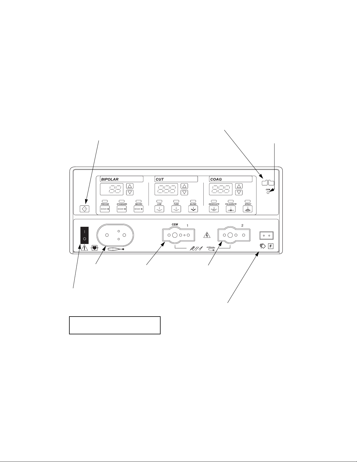
Front Panel
Layout of controls and indicators on the front panel
Recall button
Pressing this button sets the
generator to the most recently
used mode and power settings.
REM alarm indicator
CEM
indicator
Bipolar controls
Bipolar
instrument
receptacle
Power switch
This switch supplies power
to the generator.
To turn on the generator, press (|).
To turn off the generator, press (
Monopolar 1/CEM
Cut controls
instrument
receptacle
O).
Coag controls
Monopolar 2
instrument
receptacle
Patient return electrode
receptacle
For monopolar electrosurgery,
connect a patient return
electrode to this receptacle.
2-2 Force FX Electrosurgical Generator C Service Manual
Bipolar Controls
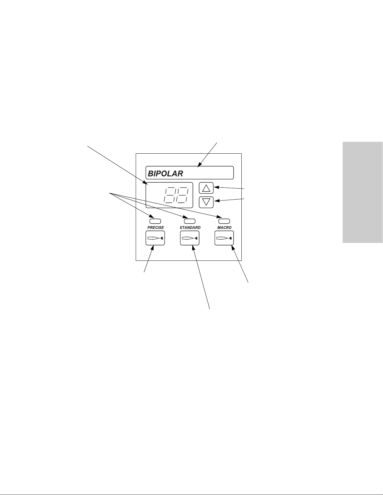
Buttons and indicators for bipolar contro ls
Bipolar Controls
Bipolar display
Shows the power setting,
in watts, for the selected
mode.
Mode indicators
Illuminate green when
you press the
corresponding mode
button.
Precise mode button
Select for fine bipolar
tissue desiccation.
Bipolar indicator
When you activate bipolar, this
indicator illuminates blue and
an activation tone sounds.
Power buttons
Δ to increase the power.
Press
Press ∇ to decrease the power.
Macro mode button
Select for macrobipolar output.
Controls, Indicators,
and Receptacles
Standard mode button
Select for standard bipolar tissue
desiccation. This is the default
bipolar mode.
Force FX Electrosurgical Generator C Service Manual 2-3

Bipolar Instrument Receptacle
Bipolar Instrument Receptacle
Caution
Connect accessories to the proper receptacle type. In particular, bipolar accessories
must be connected to the Bipolar Instrument receptacle only. Improper connection
may result in inadvertent generator activation or a REM contact quality monitor
alarm.
You can connect either a footswitching or handswitching bipolar instrument to the
Bipolar instrument receptacle.
Connect a footswitching instrument with a two-pin connector.
or
Connect a handswitching instrument with a three-pin connector.
2-4 Force FX Electrosurgical Generator C Service Manual

Monopolar Cut Controls
Buttons and indicators for cut controls (monopolar)
Monopolar Cut Controls
Cut display
Shows the power
setting, in watts, for the
selected mode.
Mode indicators
Illuminate green when
you press the
corresponding mode
button.
Low mode button
Select for a cut with little
or no sparking.
Cut indicator
When you activate cut, this
indicator illuminates yellow and
an activation tone sounds.
Power buttons
Press
Press ∇ to decrease the power.
Blend mode button
Select for slower cutting and
additional hemostasis.
Controls, Indicators,
and Receptacles
Δ to increase the power.
Pure mode button
Select for an even cut with little or no
hemostasis. This is the default monopolar cut
mode.
Force FX Electrosurgical Generator C Service Manual 2-5
Monopolar Coag Controls
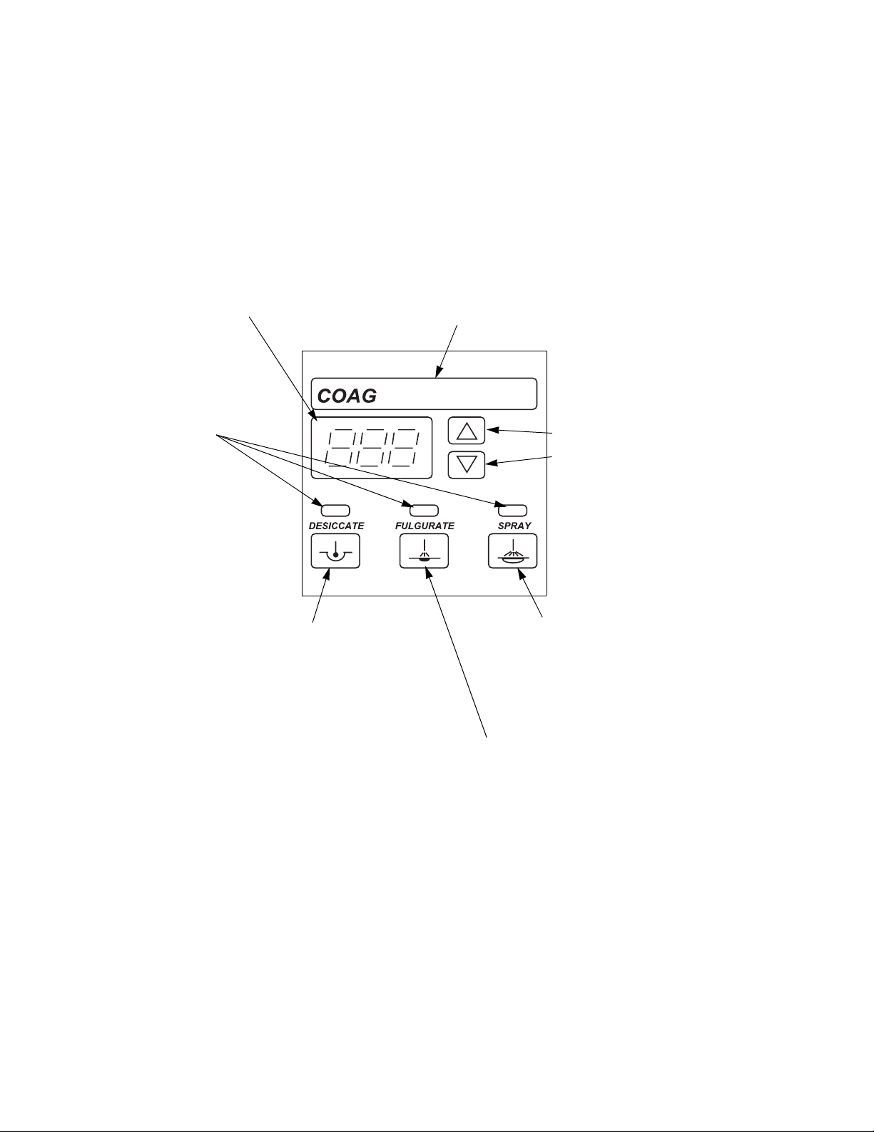
Monopolar Coag Controls
Buttons and indicators for coag controls (monopolar)
Coag display
Shows the power
setting, in watts, for
the selected mode.
Mode indicators
Illuminate green when
you press the
corresponding mode
button.
Desiccate mode button
Select to desiccate the area
of tissue that is in direct
contact with the active
electrode.
Coag indicator
When you activate coag, this
indicator illuminates blue and
an activation tone sounds.
Power buttons
Press
Press ∇ to decrease the power.
Spray mode button
Select to evenly coagulate a wide
area of tissue with a spray of
sparks; penetration is shallower
and tissue area is larger than in
fulgurate mode.
Δ to increase the power.
Fulgurate mode button
Select to fulgurate an area of tissue with a
spray of sparks.
This unit is equipped with an additional
fulgurate mode which incorporates a lower
crest factor (LCF) than the factory default
fulgurate mode. For details about this
additional fulgurate mode, LCF Fulgurate,
refer to Chapter 4, Before Surgery, in the
Force FX Electrosurgical Generator C User’s
Guide.
Fulgurate is the default monopolar coag
mode. However, the default coag mode
can be changed to either Desiccate or Spray
through the serial port on the rear panel.
2-6 Force FX Electrosurgical Generator C Service Manual
Monopolar Instrument Receptacles
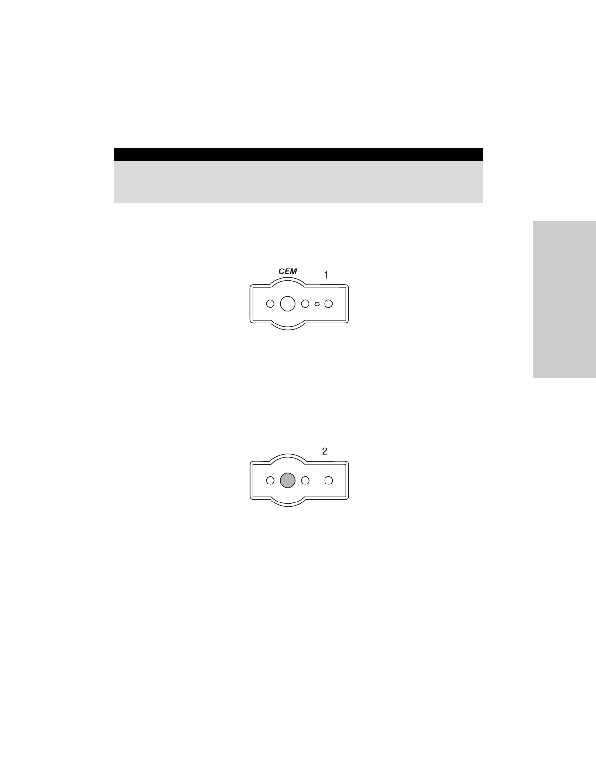
Monopolar Instrument Receptacles
Warning
The instrument receptacles on this generator are designed to accept only one instrument at a
time. Do not attempt to connect more than one instrument at a time into a given receptacle.
Doing so will cause simultaneous activation of the instruments.
You can connect a footswitching or handswitching monopolar instrument to the
monopolar receptacles. Some footswitching instruments may require a single-pin adapter
(E0502 Series or E0017), available from Covidien.
Connect one monopolar instrument to the Monopolar 1/CEM Instrument receptacle:
Controls, Indicators,
and Receptacles
• A single-pin footswitching instrument or a three-pin handswitching instrument
or
• A four-pin CUSA handpiece with CEM nosecone. (The CEM indicator in the upper
right of the front panel illuminates green.) Refer to Connecting the CUSA Handpiece
with CEM Nosecone on page 5-11.
Connect one monopolar instrument to the Monopolar 2 Instrument receptacle:
• A single-pin footswitching instrument or a three-pin handswitching instrument.
Force FX Electrosurgical Generator C Service Manual 2-7
REM Alarm Indicator
REM Alarm Indicator
This indicator illuminates red until you properly apply a REM PolyhesiveTM Patient Return
Electrode to the patient and connect it to the generator. Then the indicator illuminates
green. (When you connect an electrode without the REM safety feature, the indicator
does not illuminate.)
If the REM system senses an alarm condition, the indicator flashes red until you correct
the alarm condition—then the indicator illuminates green. (If you are using a return
electrode without the REM safety feature, the red indicator light is extinguished when
you correct the alarm condition.)
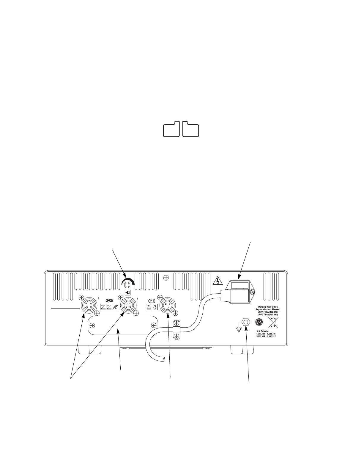
Rear Panel
Controls and receptacles on the rear panel
Volume control
Option panel
Monopolar
Footswitch
receptacles
Bipolar
Footswitch
receptacle
Power entry module
Equipotential grounding lug
Use to connect the generator to
earth ground.
2-8 Force FX Electrosurgical Generator C Service Manual

Footswitch Receptacles
Footswitch Receptacles
The rear panel contains three footswitch receptacles: two for monopolar and one for
bipolar.
Monopolar Footswitch Receptacles
You must connect a monopolar footswitch if you connect a monopolar footswitching
instrument to the generator.
Use only a Valleylab monopolar footswitch with the Force FX Electrosurgical Generator C.
Use of an incompatible footswitch may cause unexpected output.
Connect a two-pedal Valleylab monopolar footswitch to the Monopolar 1 Footswitch
receptacle.
1
Controls, Indicators,
and Receptacles
The connected footswitch activates monopolar output for the instrument that is
connected to the Monopolar 1/CEM Instrument receptacle on the front panel.
Connect a two-pedal monopolar footswitch to the Monopolar 2 Footswitch receptacle.
2
The connected footswitch activates monopolar output for the instrument that is
connected to the Monopolar 2 Instrument receptacle on the front panel.
Bipolar Footswitch Receptacle
You must connect a bipolar footswitch if you connect a bipolar footswitching instrument
to the generator.
Connect a single-pedal bipolar footswitch to the Bipolar Footswitch receptacle.
The connected footswitch activates bipolar output for the instrument that is connected
to the Bipolar Instrument receptacle on the front panel.
Force FX Electrosurgical Generator C Service Manual 2-9
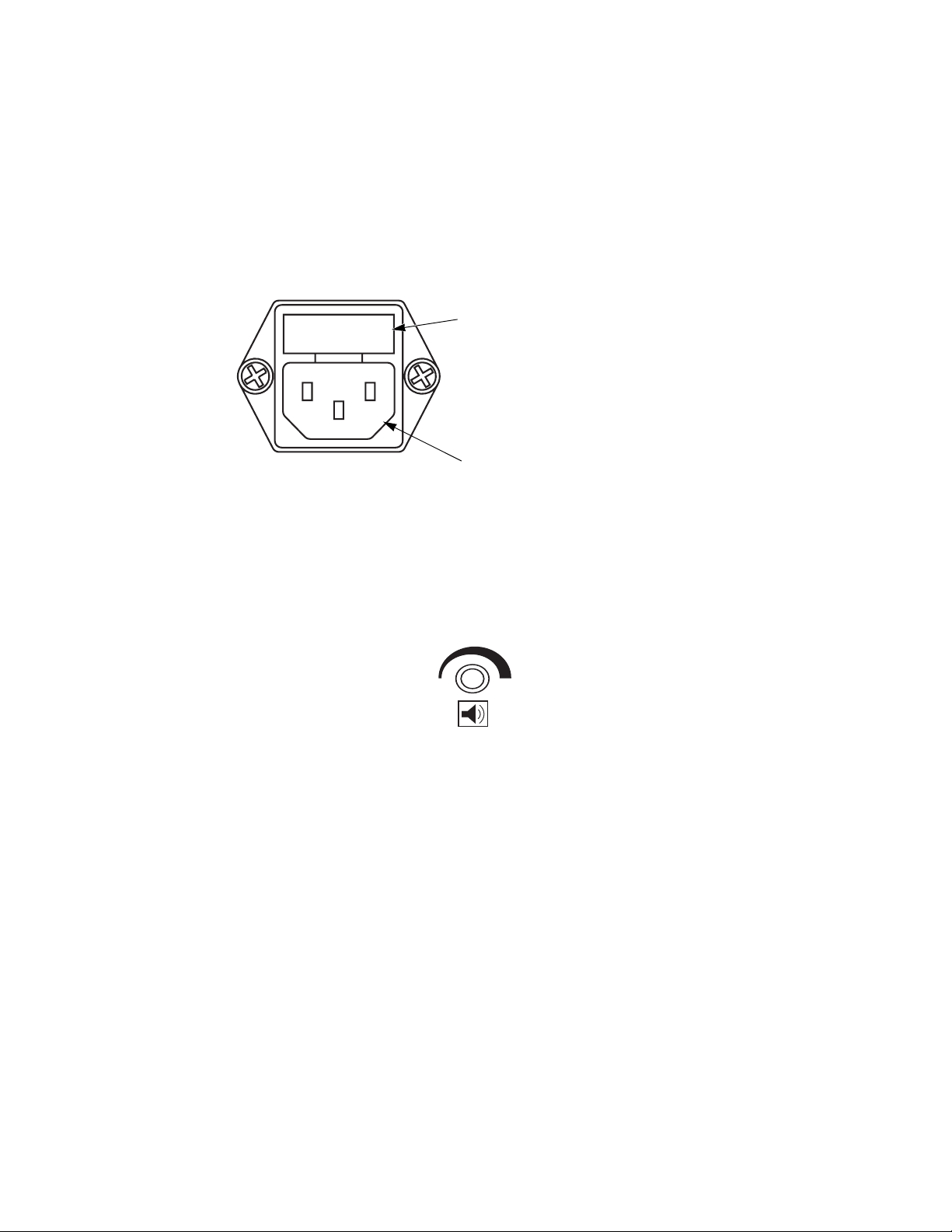
Power Entry Module
Power Entry Module
The power entry module consists of a power cord receptacle and a fuse drawer.
Components in the power entry module
Fuse drawer
The fuse drawer contains two fuses. Refer
to Fuse Replacement on page 7-13 for
instructions on changing the fuses.
Power cord receptacle
Activation Tone Volume Control
Turn to adjust the volume of the tones that sound when the generator is activated
(activation tone). To ensure that the surgical team is alerted to inadvertent activation,
these tones cannot be silenced.
To increase the volume of activation tones, turn the knob clockwise.
To decrease the volume, turn the knob counterclockwise.
2-10 Force FX Electrosurgical Generator C Service Manual
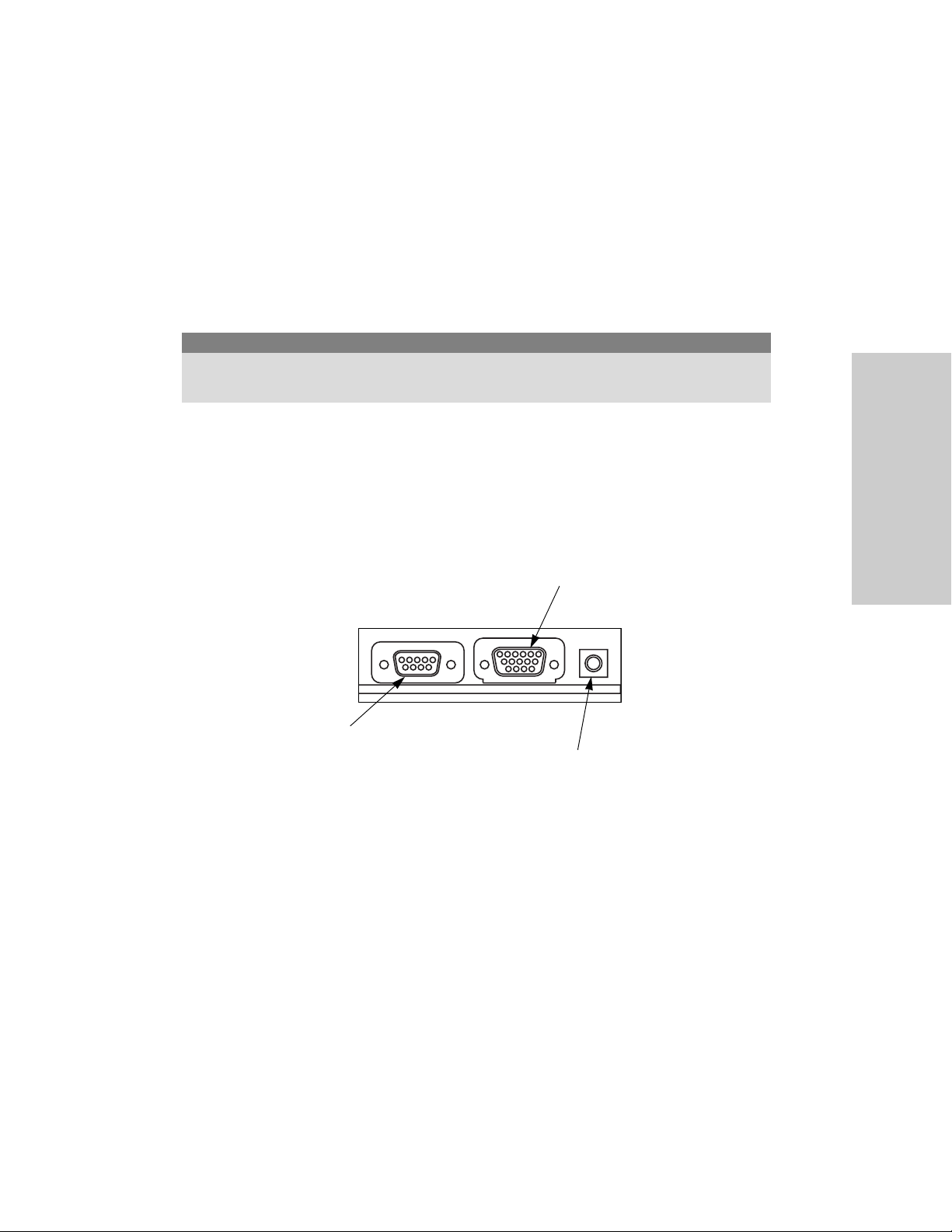
Option Panel
A removable plate on the rear panel covers a serial port, an expansion port, and a radio
frequency (RF) activation port. Remove this plate to obtain information through the RS232 port or to install a peripheral device such as a Bipolar Current Monitor, but retain the
original cover plate. After obtaining information or removing a peripheral device, reinstall
the original cover plate.
Caution
To avoid product damage, do not operate the Force FX Electrosurgical Generator C without an
appropriate cover plate in place.
To review the technical specifications for each port, refer to page 3-5 and page 3-6.
The three ports behind the option panel
Expansion port
Allows a connected device to receive
information about the RF voltage and
current being generated as well as signal
the generator to halt RF output.
Option Panel
Controls, Indicators,
and Receptacles
Serial port
Allows connection of a computer to the
generator. You can obtain information
about the generator using RS-232
communications protocol or change the
default coag mode from Fulgurate to
Desiccate or Spray. Refer to Using the RS-
232 Serial Port on page 5-42, for
instructions.
RF Activation port
Allows a connected device to
receive information during RF
activation of the generator,
which will then generate a
response in the device.
Force FX Electrosurgical Generator C Service Manual 2-11


Chapter 3
Technical Specifications
All specifications are nominal and subject to change without notice. A
specification referred to as “typical” is within ± 20% of a stated value at room
temperature (77° F/25° C) and a nominal input power voltage.
Force FX Electrosurgical Generator C Service Manual 3-1

Performance Characteristics
Performance Characteristics
General
Output configuration Isolated output
Cooling Natural convection; side and rear panel vents; fan
Display Eight digital seven-segment displays: 0.75" (1.9 cm)
Mounting Universal cart (UC8009), CUSA EXcel System, a
each
Valleylab Argon Gas Delivery Unit II, or any stable flat
surface
Dimensions and Weight
Width 14" (35.6 cm)
Depth 18" (45.7 cm)
Height 4 3/8" (11.1 cm)
Weight <18 lb (< 8.2 kg)
Operating Parameters
Ambient temperature
range
Relative humidity 30% to 75%, noncondensing
Atmospheric pressure 700 to 1060 millibars
Warm-up time If transported or stored at temperatures outside the
50° to 104° F (10° to 40° C)
operating temperature range, allow one hour for the
generator to reach room temperature before use.
3-2 Force FX Electrosurgical Generator C Service Manual
 Loading...