

Page 1
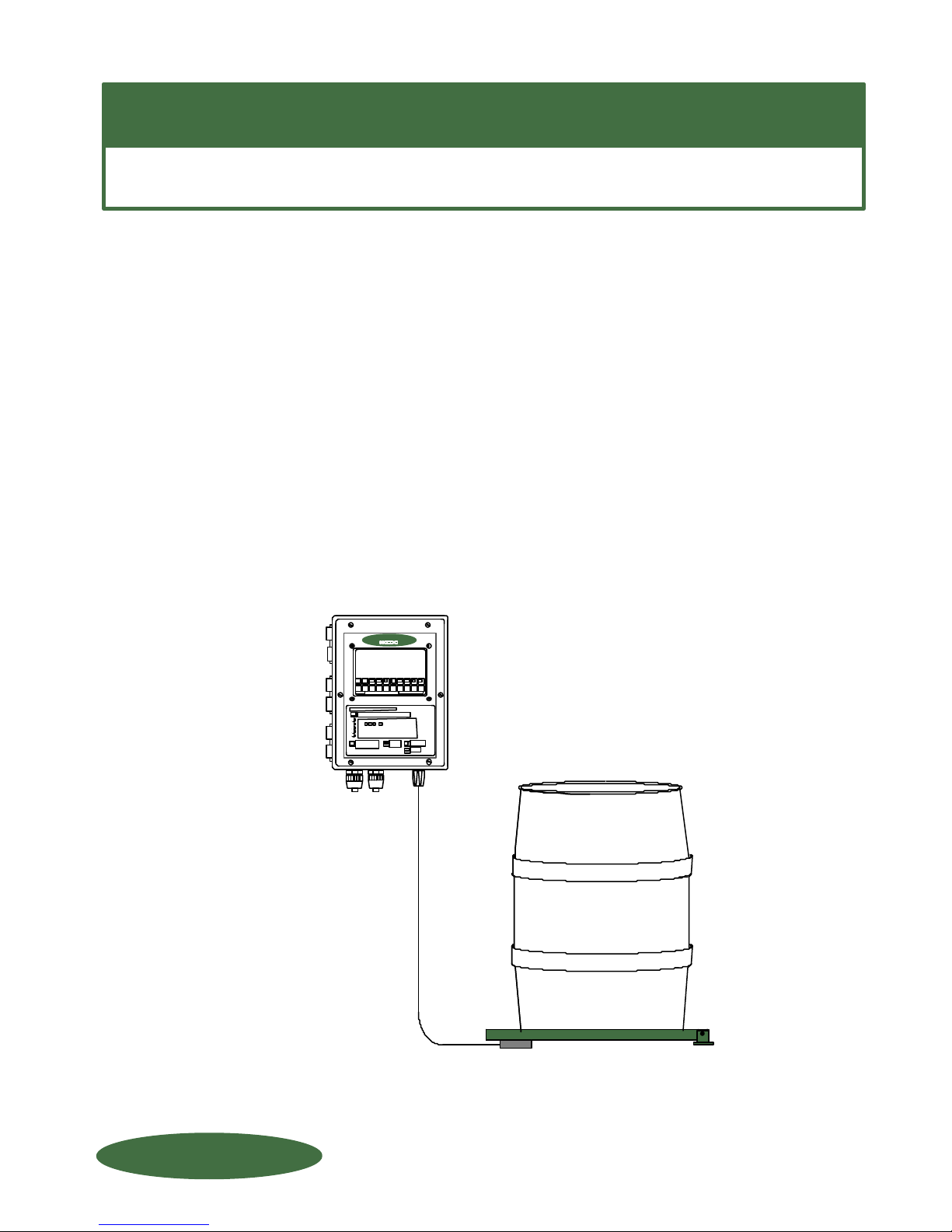
WIZARD 4000
DRUMM-SCALE
SCALE:
SCALE:
INDICATOR:
INDICATOR:
DRUMM-SCALE
DRUMM-SCALE
WIZARD 4000
WIZARD 4000
INSTALLATION & OPERATION
electronic 30- to 55-gallon drums
electronic 30- to 55-gallon drums
1- to 4-Channel Wizard Indicator
1- to 4-Channel Wizard Indicator
TM
7
7
to 1,000 lb. with
to 1,000 lb. with
factory calibrated
factory calibrated
s/n __________________
s/n __________________
FORCE FLOW
FORCE FLOW
WIZARD 4000
WIZARD 4000
SCALE 1 350 LBS
091234567
8
FORCE FLOW
FORCE FLOW
FFLLOOQQIIUUP
P
Version: PR128G
Version: PR128G
1150-D Burnett Ave, Concord, CA 94520 USA
1150-D Burnett Ave, Concord, CA 94520 USA
REF: T4\O&M\DRUMWIZ\CVRDRMWZ.tcw (G00.pdf)
REF: T4\O&M\DRUMWIZ\CVRDRMWZ.tcw (G00.pdf)
1-800-893-6723 Fax: 925-686-6713
1-800-893-6723 Fax: 925-686-6713
www.forceflow.com / [email protected]
www.forceflow.com / [email protected]
Page 2

INCLUDES MODELS:
ELECTRONIC
DRUMM-SCALE
with WIZARD 4000 DIGITAL INDICATOR
FOR CAPACITIES:
FOR PLATFORM SIZES:
COVERING MODELS:
Includes Stainless Steel Models
400 lbs. (181 kg) thru 1,000 lbs. (454 kg)
27-1/2" x 27-1/2" (699mm x 699mm)
400 lbs.
600 lbs.
800 lbs.
1000 lbs.
27-DR4DS
27-DR6DS
27-DR8DS
27-DR10DS
(Metric: DR2KDS 200 kg)
(Metric: DR3KDS 300 kg)
(Metric: DR4KDS 400 kg)
(Metric: DR5KDS 500 kg)
FORCE FLOW
FORCE FLOW
FFLLOOQQIIUUP
P
1150-D Burnett Ave, Concord, CA 94520 USA
1-800-893-6723 US & Canada, Fax: 925-686-6713
WWW.FORCEFLOW.COM / [email protected]
REF: T4\O&M\DRUMELEC\MODELNOS.tcw (G0A.pdf)
Page 3
SECTION
INDEX
WIZARD Indicator with DRUMM-SCALE
W.1.000
YOU
ARE
HERE !
W.2.000
INSTALLATION OF SCALE PLATFORM:
W.1.101
W.1.102
Installation Instructions
Dimensional Drawing
INSTALLATION OF LOAD CELL
W.1.141
Load Cell Installation Drawing
INDICATOR INSTALLATION
W.1.201
W.1.202-203
W.1.204
Indicator Wiring & Plumbing
Indicator Installation Instructions
Wizard Component Layout
INSTALLATION CHECK OFF LISTS
W.1.301
W.1.305
Installation Check-Off List
Installation Start-Up Check-Off List
INDICATOR OPERATION
W.2.101
W.2.102
W.2.103
Keyboard Display Selections
Keyboard Menu - Quick Reference
Tank Load Mode
MEMU OF DAY-TO-DAY OPERATIONS
W.2.104
W.2.105
W.2.106
W.2.107
W.2.108
Low Level Alarm & Date Last Cleared
Clear Amount Used & Set Scale Zero
Set Scale Zero cont... & Allarm Reset
Review Daily Usage & Printing Report
Report (example) & Protocol
SET-UP CODES - CUSTOM FORMATTING
W.2.201
W.2.202
W.2.203
W.2.204
W.2.205
W.2.206
W.3.000
MISCELLANEOUS
W.3.101
W.3.201
W.3.301
W.3.401
FORCE FLOW
FORCE FLOW
FFLLOOQQIIUUP
P
Code 9080 (Scale Set Up)
Code 9082-9083 (Feed Rate Format/Display Units)
Code 9084-9086 (Single or Dual Display/Tank Loading/Printer)
Code 9086 (cont...)-9089 (Time/Date/Calibration/Channels)
Code 4200 & 3256 (Set Point Configuration/4-20mA Output Configuration)
Code 3256 (cont...)
Code 9081 (Field Calibration)
Checking Calibration via Water Test
Troubleshooting Tips
Spare Parts List
1150-D Burnett Ave, Concord, CA 94520 USA
1-800-893-6723 US & Canada, Fax: 925-686-6713
www.forceflow.com / [email protected]
REF: T4\O&M\INDEX.\Y07.tcw etc (Y07.pdf etc) 1/24/02
Page 4

INSTALLATION
DRUMM-SCALE with ELECTRONIC INDICATOR
(1,000 lb. or 500 kg. Capacity)
DRUMM-SCALE SCALES
for PORTABLE Drums
INSTALLATION:
(See Installation Drawings 29886 and 29895 for Drumm-Scale)
1 Position scale platform on level surface. The hinge and load cell must be adequately supported
by concrete slab or other suitable substrate.
2 Anchor hinge to ground or substrate using suitable anchors. DO NOT OPERATE SCALE
UNLESS IT IS ANCHORED TO GROUND !
3 Install shear-beam load cell using 2 flat head socket screws, shim plate and threaded nuts per
Drawing 29886 and Drawing 29895. Load cell “arrow” should point upward, load button with jam
nut should face toward ground with shim plate between load cell and platform.
4 Level the platform by threading the load button in or out and locking the jam nut in place when
level. DO NOT extend the load button beyond the available threads in the load cell. This will
cause the improper operation of your scale. The load button is all that contacts the ground.
5 Feed load cell cable through notch in side of platform and use tab to keep cable suspended and
clear of platform edge and obstructions.
6 The Load Cell is equipped with 20' of shielded cable which connects to the inside of the bottom of
the indicator (see page 6). If you are imbedding conduit in your concrete pad, between your scale
and indicator, we recommend 1-1/2" ID conduit so you can fit all your load cell cables in one
conduit. DO NOT run any other inductive load with your load cell cable. Wire load cell cable to
indicator per indicator wiring instructions Page 9.
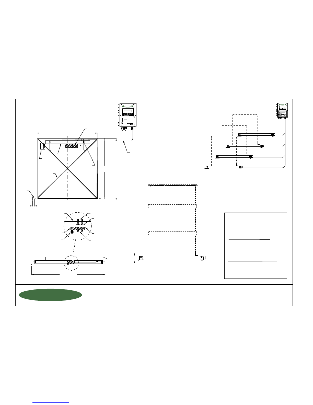
7 Measure the diameter of your drum and set the backstop on the platform to the drum diameter
using the calibration grid.
REF: WP File: O&M\DRUMWIZ\ELECDRUM.wpd (T01.pdf) QUESTIONS ? Call our HELP HOTLINE 1-800-893-6723
W.1.101
S.1.101
Page 5
C
L
________ Model Number of Platform
________ Model Number of Indicator
________ Feet of Cable (20' Std)
________ Pound or Kilo Indicator
________ Number of Scales
27 1/2"
(699mm)
27 1/2"
(699mm)
27 3/4"
(705mm)
2"
(51mm)
31 1/2" (800mm)
Mounting Bolt Sleeves
Mounting Bolt Sleeves
Load Button & Jam Nut
Arrow Facing Up
Scale Platform
Spacer
Shear Beam Load Cell
Platform
Cross Brace
Calibration
Grid
Backstop
Load Cell Anchor
Bolt Holes in Platform
Tab Guide
for Cable
Load Cell
Cable to
Indicator
1150-D Burnett Ave, Concord, CA 94520 USA
1-800-893-6723 US & Canada, Fax: 925-686-6713
www.forceflow.com / [email protected]
Drawn by: SLP
Date: 09/01/95
Revised:
Scale: NONE
Drawing Number
File: T4\O&M\DRUMELEC\DRUMWIZ.tcw (G02.pdf) (WEB: DRUMWIZ.pdf) 01/24/02
30290
ELECTRONIC DRUMM-SCALE
with WIZARD INDICATOR
for 30- to 55-Gallon Drums
(Capacities to 1000 lbs or 500 kg)
FORCE FLOW
FORCE FLOW
FFLLOOQQIIUUP
P
1/2"
9/16"
Hole
DR4DSS ( 400 lb) DR2KDSS (200 kg)
DR5DSS ( 500 lb) DR2.5KDSS (250 kg)
DR6DSS ( 600 lb) DR3KDSS (300 kg)
DR8DSS ( 800 lb) DR4KDSS (400 kg)
DR10DSS (1,000 lb) DR5KDSS (500 kg)
DR4DS ( 400 lb) DR2KDS (200 kg)
DR5DS ( 500 lb) DR2.5KDS (250 kg)
DR6DS ( 600 lb) DR3KDS (300 kg)
DR8DS ( 800 lb) DR4KDS (400 kg)
DR10DS (1,000 lb) DR5KDS (500 kg)
MODEL NUMBER (for WIZARD 4000 Indicator)
4000-1 1-Channel WIZARD 4000 Indicator
4000-2 2-Channel WIZARD 4000 Indicator
4000-3 3-Channel WIZARD 4000 Indicator
4000-4 4-Channel WIZARD 4000 Indicator
EPOXY MODEL (Platform with Load Cell)
316 SS MODEL (Platform with Load Cell)
W.1.102
Page 6
SECTION
INDEX
WIZARD Indicator with DRUMM-SCALE
W.1.000
YOU
ARE
HERE !
W.2.000
INSTALLATION OF SCALE PLATFORM:
W.1.101
W.1.102
Installation Instructions
Dimensional Drawing
INSTALLATION OF LOAD CELL
W.1.141
Load Cell Installation Drawing
INDICATOR INSTALLATION
W.1.201
W.1.202-203
W.1.204
Indicator Wiring & Plumbing
Indicator Installation Instructions
Wizard Component Layout
INSTALLATION CHECK OFF LISTS
W.1.301
W.1.305
Installation Check-Off List
Installation Start-Up Check-Off List
INDICATOR OPERATION
W.2.101
W.2.102
W.2.103
Keyboard Display Selections
Keyboard Menu - Quick Reference
Tank Load Mode
MEMU OF DAY-TO-DAY OPERATIONS
W.2.104
W.2.105
W.2.106
W.2.107
W.2.108
Low Level Alarm & Date Last Cleared
Clear Amount Used & Set Scale Zero
Set Scale Zero cont... & Allarm Reset
Review Daily Usage & Printing Report
Report (example) & Protocol
SET-UP CODES - CUSTOM FORMATTING
W.2.201
W.2.202
W.2.203
W.2.204
W.2.205
W.2.206
W.3.000
MISCELLANEOUS
W.3.101
W.3.201
W.3.301
W.3.401
FORCE FLOW
FORCE FLOW
FFLLOOQQIIUUP
P
Code 9080 (Scale Set Up)
Code 9082-9083 (Feed Rate Format/Display Units)
Code 9084-9086 (Single or Dual Display/Tank Loading/Printer)
Code 9086 (cont...)-9089 (Time/Date/Calibration/Channels)
Code 4200 & 3256 (Set Point Configuration/4-20mA Output Configuration)
Code 3256 (cont...)
Code 9081 (Field Calibration)
Checking Calibration via Water Test
Troubleshooting Tips
Spare Parts List
1150-D Burnett Ave, Concord, CA 94520 USA
1-800-893-6723 US & Canada, Fax: 925-686-6713
www.forceflow.com / [email protected]
REF: T4\O&M\INDEX.\Y07.tcw etc (Y07.pdf etc) 1/24/02
Page 7
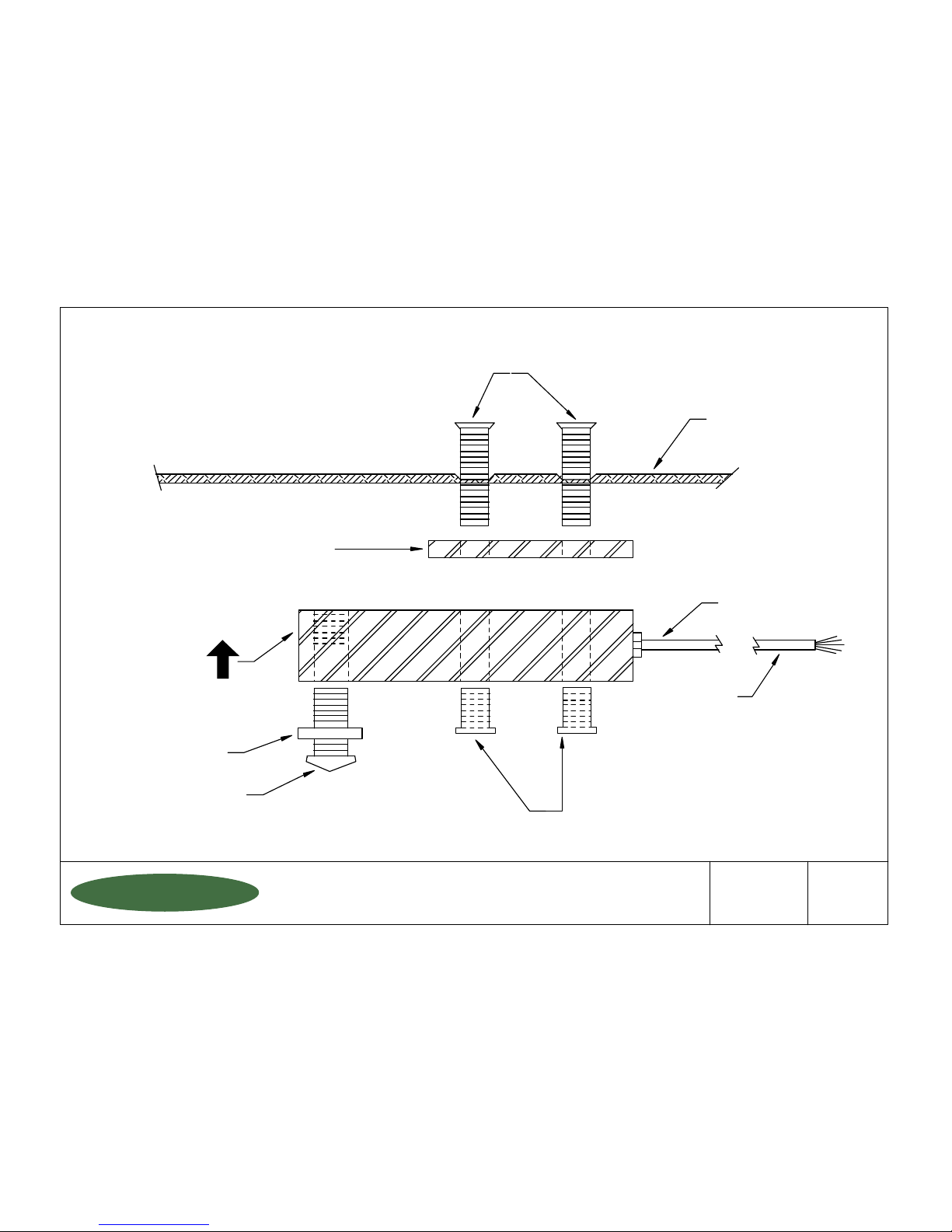
Mounting Bolts
Spacer
Arrow facing up
Load Button
Mounting Bolt Sleeves
Drumm-Scale
Platform Frame
Jam Nut
Strain Relief
Cable
1150-D Burnett Ave, Concord, CA 94520 USA
1-800-893-6723 US & Canada, Fax: 925-686-6713
www.forceflow.com / [email protected]
Drawn by: SLP
Date: 09/01/95
Revised: 05/20/97
Scale: NONE
Drawing Number
File: T4\O&M\DRUMWIZ\DRDRUMLC.tcw (T03.pdf)
29886
DRUMM-SCALE
Load Cell Mounting Drawing
FORCE FLOW
FORCE FLOW
FFLLOOQQIIUUP
P
S.1.141
W.1.141
Page 8
SECTION
INDEX
WIZARD Indicator with DRUMM-SCALE
W.1.000
YOU
ARE
HERE !
W.2.000
INSTALLATION OF SCALE PLATFORM:
W.1.101
W.1.102
Installation Instructions
Dimensional Drawing
INSTALLATION OF LOAD CELL
W.1.141
Load Cell Installation Drawing
INDICATOR INSTALLATION
W.1.201
W.1.202-203
W.1.204
Indicator Wiring & Plumbing
Indicator Installation Instructions
Wizard Component Layout
INSTALLATION CHECK OFF LISTS
W.1.301
W.1.305
Installation Check-Off List
Installation Start-Up Check-Off List
INDICATOR OPERATION
W.2.101
W.2.102
W.2.103
Keyboard Display Selections
Keyboard Menu - Quick Reference
Tank Load Mode
MEMU OF DAY-TO-DAY OPERATIONS
W.2.104
W.2.105
W.2.106
W.2.107
W.2.108
Low Level Alarm & Date Last Cleared
Clear Amount Used & Set Scale Zero
Set Scale Zero cont... & Allarm Reset
Review Daily Usage & Printing Report
Report (example) & Protocol
SET-UP CODES - CUSTOM FORMATTING
W.2.201
W.2.202
W.2.203
W.2.204
W.2.205
W.2.206
W.3.000
MISCELLANEOUS
W.3.101
W.3.201
W.3.301
W.3.401
FORCE FLOW
FORCE FLOW
FFLLOOQQIIUUP
P
Code 9080 (Scale Set Up)
Code 9082-9083 (Feed Rate Format/Display Units)
Code 9084-9086 (Single or Dual Display/Tank Loading/Printer)
Code 9086 (cont...)-9089 (Time/Date/Calibration/Channels)
Code 4200 & 3256 (Set Point Configuration/4-20mA Output Configuration)
Code 3256 (cont...)
Code 9081 (Field Calibration)
Checking Calibration via Water Test
Troubleshooting Tips
Spare Parts List
1150-D Burnett Ave, Concord, CA 94520 USA
1-800-893-6723 US & Canada, Fax: 925-686-6713
www.forceflow.com / [email protected]
REF: T4\O&M\INDEX.\Y07.tcw etc (Y07.pdf etc) 1/24/02
Page 9
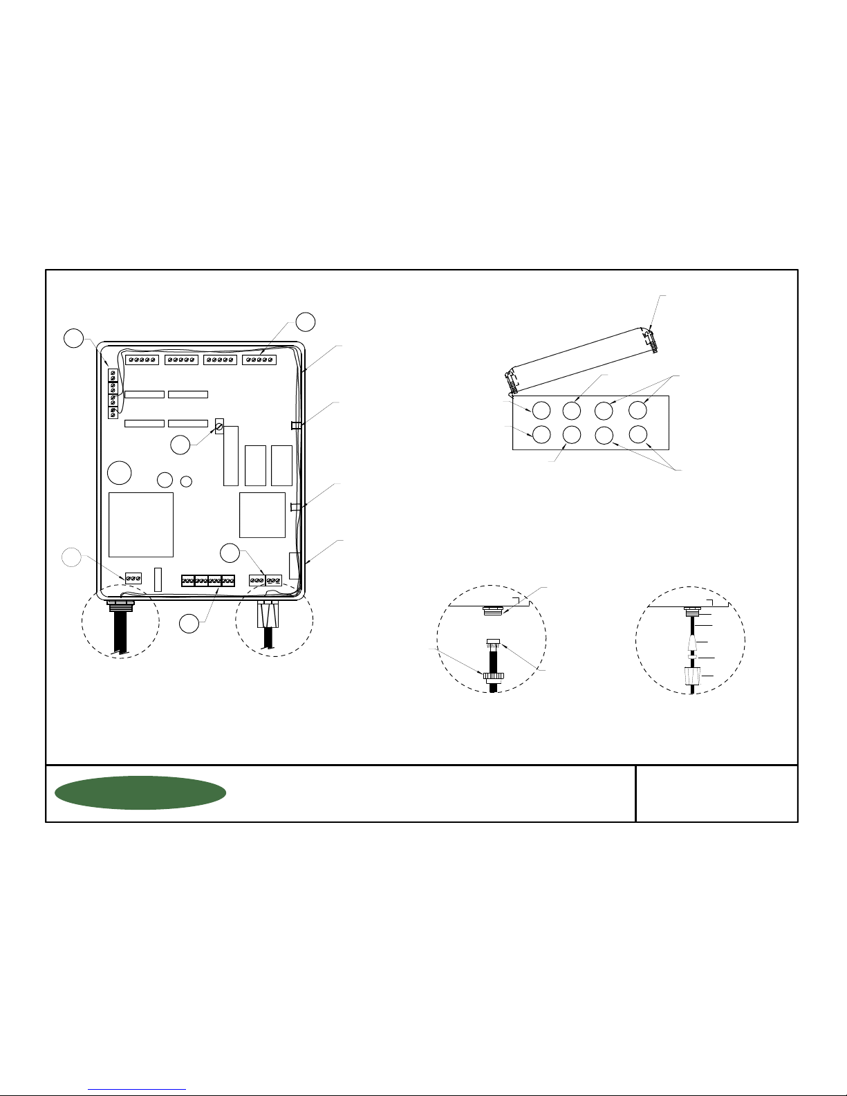
4-20mA
CONNECTIONS
LOAD CELL/ULTRASONIC CONNECTIONS
RELAYS
#1
#2
#3
#4
RS485/RS232
#1 #2 #3 #4
DISPLAY ANGLE
ADJUSTMENT (BLUE)
EPROM
RAM
CPU
POWER SUPPLY
POWER IN
CONNECTOR SLEEVE
PLASTIC WASHER
RUBBER GROMMET
CABLE
CONDUIT FITTING
BOX
#1 #2 #3 #4
BOX (FRONT VIEW)
1/4" CORD CONNECTOR, USED FOR:
3
2
4
1
6 SLOTTED PAN HEAD SCREWS.
(TIGHTEN SCREWS EVENLY TO
GET UNIFORM SEAL ON COVER GASKET)
3RD: ATTACH TO CONDUIT
OR CABLE CONNECTOR
FITTING ON BOX
2ND: SCREW CONDUIT
CONNECTOR ONTO
CONDUIT
1ST: SLIP CONDUIT
FITTING BASE
OVER CONDUIT
1/2" CONDUIT CONNECTOR, USED FOR:
5
LOAD CELL CABLE
ULTRASONIC CABLE
POWER
4-20 MA SIGNAL
RELAY WIRING
COMMUNICATIONS)
6
NOTE:
Mount Indicator at "EYE LEVEL"
with the mounting fixtures provided.
FUSE
BOX (BOTTOM VIEW)
1
3
4
2
1150-D Burnett Ave, Concord, CA 94520 USA
1-800-893-6723 US & Canada, Fax: 925-686-6713
www.forceflow.com / [email protected]
Drawn by: SLP
Date: 09/01/95
Revised: 01/17/01
Scale: NONE
Drawing Number
File: T4\O&M\AWIZMSTR\WIZINDI.tcw (B01.pdf)
29893
INDICATOR WIRING &
PLUMBING INSTRUCTIONS
FORCE FLOW
FORCE FLOW
FFLLOOQQIIUUP
P
4-20mA WIRING,
LOAD CELL CABLE,
ULTRASONIC CABLE
WIRE/CABLE
CLAMP
WIRE/CABLE
CLAMP
OPTIONAL
AUDIBLE
ALARM
CORD
CONNECTION
CONDUIT
CONNECTION
LOAD CELL/ULTRASONIC (1 & 3)
(1/4" CORD CONNECTION)
4-20mA OUTPUT
(1/2" CONDUIT
CONNECTION)
RS485/RS232
(1/2" CONDUIT
CONNECTION)
110V POWER CONNECTION
(1/2" CONDUIT CONNECTION)
RELAYS (1/2" CONDUIT CONNECTION)
OPTINOAL LOAD CELL
or ULTRASONIC (2 & 4)
(1/4" CORD CONNECTION)
BOX
CONDUIT
CONNECTION
CORD
CONNECTION
W.1.201
W.1.201
Page 10
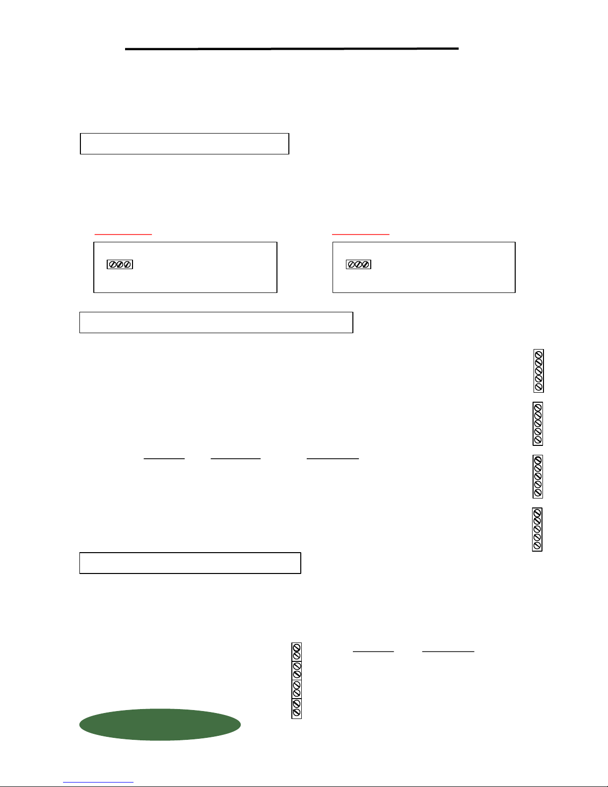
INDICATOR INSTALLATION & WIRING
ALWAYS SHUT OFF MAIN POWER, AS WELL AS POWER TO ANY AUXILIARY EQUIPMENT
THAT WILL BE INSTALLED IN THIS UNIT, BEFORE OPENING FRONT OF CASE !!
All connectors have a "PLUG IN" feature to assist in connecting wires. Remove the connector
from the board before attaching wires.
1 POWER HOOK-UP
TURN OFF MAIN POWER BEFORE CONNECTING !! Use a clean 110 Volt AC (or 220 Volt, if provided)
power line, connected directly to the main power panel at the facility. DO NOT connect any other inductive
loads, relays, etc. to this power line ! Resulting power surges can damage the electronics !!! Use far left
bottom port and connect per following: (NOTE: Use 1/2" conduit connector)
110 VOLT AC
POWER IN
+ G C
PC BOARD
+
G
C
110 Volt
Hot
Ground
Common
230 VOLT AC
POWER IN
+ G +
PC BOARD
+
G
+
2 LOAD CELL CONNECTION
DO NOT CUT LOAD CELL CABLE !! This may void your warranty!! Your WIZARD 4000
Indicator is shipped with the load cells connected and ready to power up. Should you
need to run the load cell cable through conduit, first unplug the connector from the board,
then disconnect wires, and remove by unscrewing cord connectors.
When routing load cell cable into box, use a separate 1/2" cord connector per cable. DO NOT
run load cell cable with any other inductive load or power cables !! Run load cell cable up right
hand side of enclosure and use the cable clamps provided to keep cables from laying on the
PC board. Connect load cell wires per following: (NOTE: Use 1/2" conduit connector)
PC BOARD
+ X
+ S
- S
- X
SH
WIRE COLOR
RED
GREEN
WHITE
BLACK
BRAIDED WIRE
DESCRIPTION
+ EXCITATION
+ SIGNAL
- SIGNAL
- EXCITATION
SHIELD
230 Volt
Hot
Ground
Hot
Scale #1
Scale #2
Scale #3
Scale #4
+X1
+S1
- S1
- X1
SH
+X2
+S2
- S2
- X2
SH
+X3
+S3
- S3
- X3
SH
+X4
+S4
- S4
- X4
SH
3 4-20 MA SIGNALS
Your 4-20 MA signals are internally powered for up to 900 OHMS each. DO NOT use external loop power.
Run 4-20 MA wiring up the right hand side of enclosure using the cableclamps to keep wires off of PC Board.
(NOTE: Use 1/2" conduit connector). If more than one (1) 4-20 MA signal is used, you may use the same conduit
and connector, but DO NOT run 4-20 MA signals with any other power lines, which carry an inductive load..
FORCE FLOW
FORCE FLOW
FFLLOOQQIIUUP
QUESTIONS ? Help Hotline: 1-800-893-6723
P
Scale #1
Scale #2
Scale #3
Scale #4
+
-
11
+
-
12
+
13
-
+
14
-
W.1.202
PC BOARD
+
-
DESCRIPTION
+ EXCITATION
- EXCITATION
1150-D Burnett Ave, Concord, CA 94520 USA
1-800-893-6723 US & Canada, Fax: 925-686-6713
www.forceflow.com / [email protected]
File: T4\O&M\AWIZMSTR\WZININST.tcw (B02.pdf)
Page 11
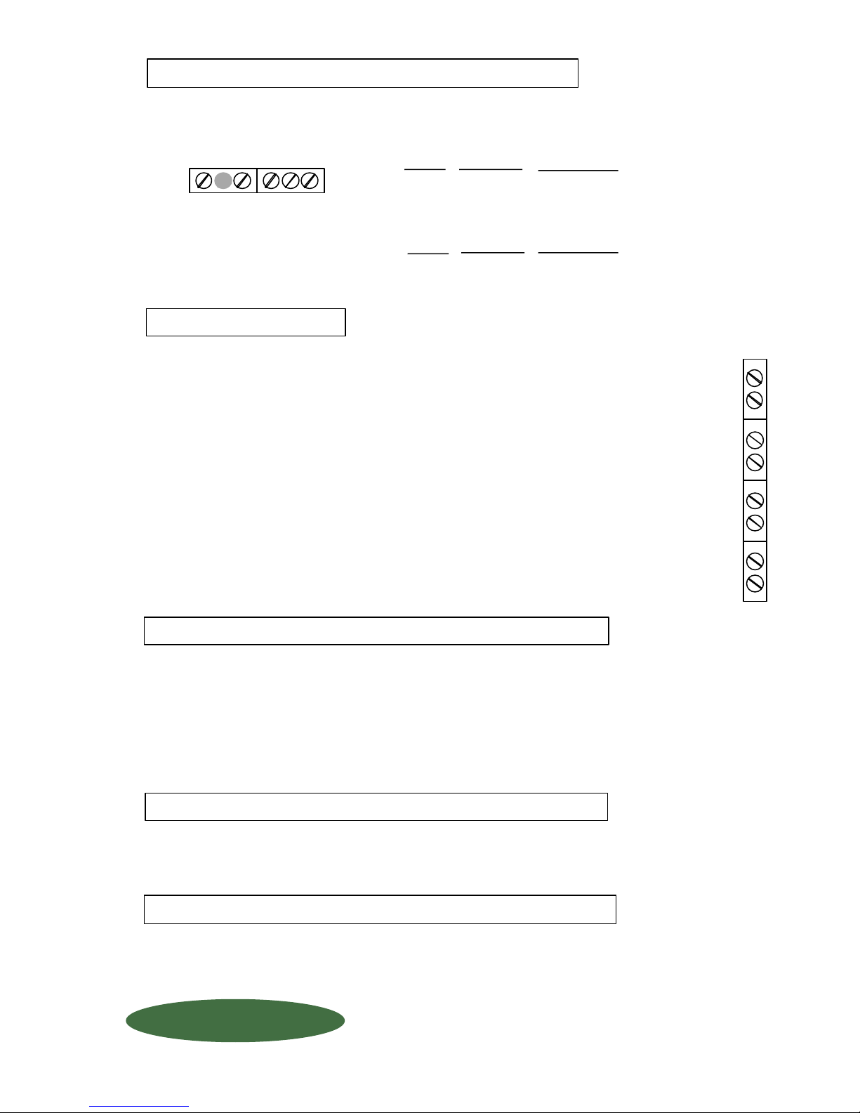
4 PRINTER COMMUNICATIONS
Use a separate conduit connector for your serial port communication. DO NOT RUN ANY OTHER
CONDUCTIVE LOAD or power lines with your communicationn wiring. Wire your communications
per the following: (NOTE: Use 1/2" conduit connector).
+ -
RS485
RS232
T G R
RS232
RS485
PC BOARD
T
G
R
PC BOARD
+
-
DESCRIPTION
Transmitted Data (printer data output line)
Signal Ground (signal)
Received Data (printer data input line)
DESCRIPTION
Positive
Negative
5 RELAYS
External apparatus (pumps, valves, alarms, etc) may be ordered either normally open
(N O) or normally closed (N C) These relays are rated at 5 AMPS maximum! To
format your relays, see Set-Up Code #4200 in Chapter "SCALE SET-UP CODES".
If more than one relay is being used, you may use the same conduit connector, but
DO NOT run any other wiring with your relays. (NOTE: Use 1/2" conduit connector).
If ordered NORMALLY OPEN:
If ordered NORMALLY CLOSED:
Circuit is NOT complete until the relay is activated.
(Example: Turning ON a warning light). We
recommend normally open for all "low level"
applications.
Circuit IS complete until relay is activated.
(Example: Turning OFF a pump)
RELAYS
IN (1)
OUT (1)
IN (2)
OUT (2)
IN (3)
OUT (3)
IN (4)
OUT (4)
#1
#2
#3
#4
6 DISPLAY ANGLE ADJUSTMENTS
Before adjusting the Display Angle Adjustment, make sure of the following:
A Indicator is mounted at "Eye Level". (Display angle is factory set for "eye level")
B POWER IS OFF !
If it is not possible to mount the indicator at eye level, you may adjust the angle of display by
turning the screw potentiometer clockwise (for down) or counterclockwise (for up). Rotate
1/2 turn at a time until display is clear.
LIGHTNING ~ SURGE PROTECTION:
Be sure that all power coming into the facility is sufficiently protected for transient lighting strikes and power
surges. Improper protection may void your warranty.
STATIC ELECTRICITY PROTECTION
CAUTION should be observed whenever box is open to avoid damage or memory loss by static
electricity. DO NOT touch any of the circuit board, other than the intended contact noted in these
instructions. Carpets, especially can build up static electricity.
FORCE FLOW
FORCE FLOW
FFLLOOQQIIUUP
QUESTIONS ? Help Hotline: 1-800-893-6723
P
W.1.203
1150-D Burnett Ave, Concord, CA 94520 USA
1-800-893-6723 US & Canada, Fax: 925-686-6713
www.forceflow.com / [email protected]
File: T4\O&M\AWIZMSTR\WZININ2A.tcw (5/27/99) (B03.pdf)
Page 12
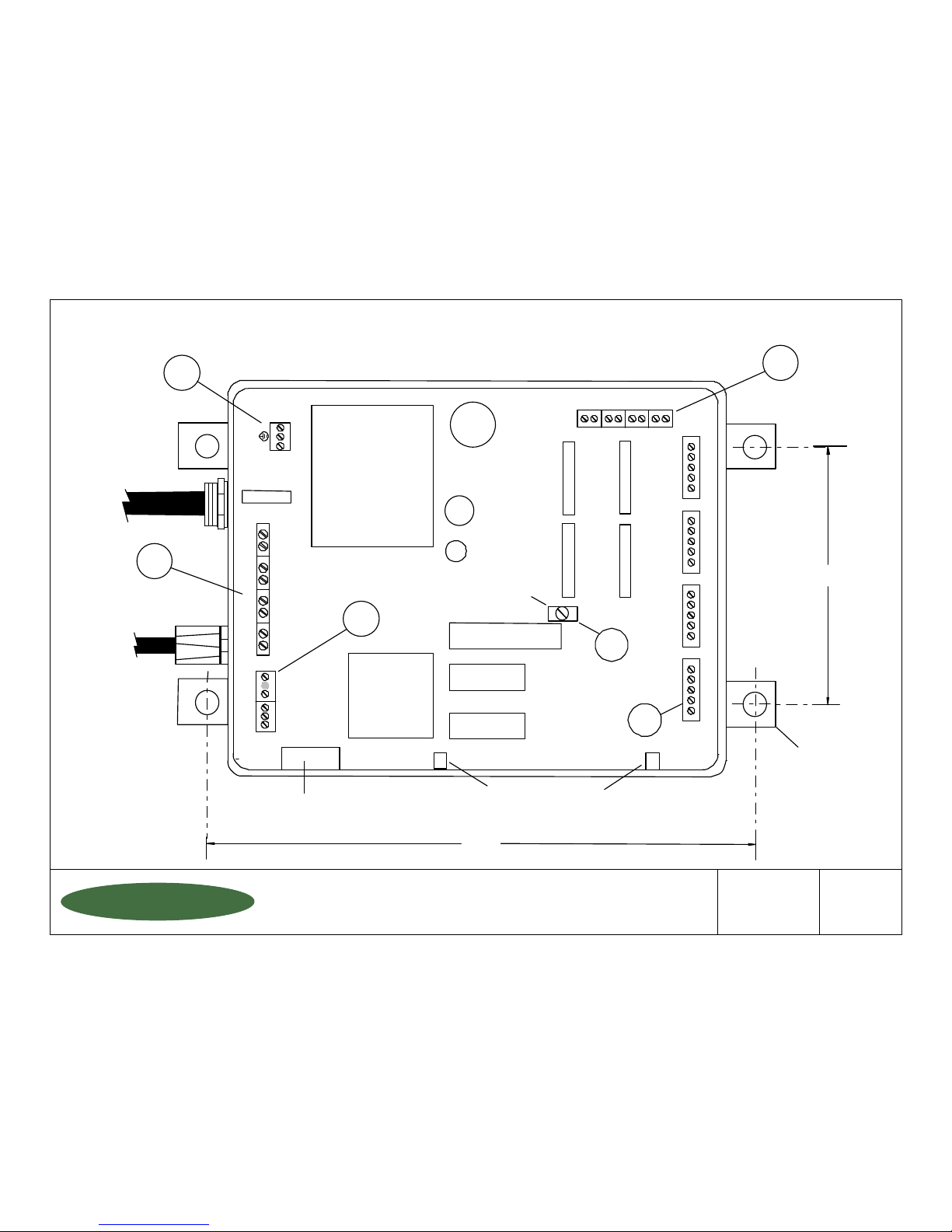
RS485
RS232
EPROM
RAM
CPU
POWER
SUPPLY
POWER IN
Scale #1
+ -
T
G
R
HI
LO
+
C
Scale #1 #2 #3 #4
- + - + - + - +
11 12 13 14
SH
-X1
+X1
+S1
-S1
+X2
+S2
-S2
-X2
SH
+X3
+S3
-S3
-X3
SH
+X4
+S4
-S4
-X4
SH
3
6
5
4
1
NOTE: For best viewing, mount indicator at "eye level"
with the mounting fixtures provided.
2
LOAD CELLS
or
ULTRASONIC
SENSORS
FUSE
RELAYS
#1
#2
#3
#4
OUR (1)
IN (1)
OUR (2)
IN (2)
OUT (3)
IN (3)
OUT (4)
IN (4)
6"
13"
WIRE CABLE CLAMP
DISPLAY ANGLE
ADJUSTMENT (Blue)
OPTIONAL
AUDIBLE
ALARM
MOUNTING
FIXTURE
4-20mA OUTPUT
1150-D Burnett Ave, Concord, CA 94520 USA
1-800-893-6723 US & Canada, Fax: 925-686-6713
www.forceflow.com / [email protected]
Drawn by: SLP
Date: 09/01/95
Revised: 05/27/99
Scale: NONE
Drawing Number
File: T4\O&M\AWZMSTR\WIZINDIA.tcw (B04.pdf) 05/27/99
29892
WIZARD INDICATOR
COMPONENT LAYOUT
FORCE FLOW
FORCE FLOW
FFLLOOQQIIUUP
P
Scale #2
Scale #3
Scale #4
W.1.204
Page 13
SECTION
INDEX
WIZARD Indicator with DRUMM-SCALE
W.1.000
YOU
ARE
HERE !
W.2.000
INSTALLATION OF SCALE PLATFORM:
W.1.101
W.1.102
Installation Instructions
Dimensional Drawing
INSTALLATION OF LOAD CELL
W.1.141
Load Cell Installation Drawing
INDICATOR INSTALLATION
W.1.201
W.1.202-203
W.1.204
Indicator Wiring & Plumbing
Indicator Installation Instructions
Wizard Component Layout
INSTALLATION CHECK OFF LISTS
W.1.301
W.1.305
Installation Check-Off List
Installation Start-Up Check-Off List
INDICATOR OPERATION
W.2.101
W.2.102
W.2.103
Keyboard Display Selections
Keyboard Menu - Quick Reference
Tank Load Mode
MEMU OF DAY-TO-DAY OPERATIONS
W.2.104
W.2.105
W.2.106
W.2.107
W.2.108
Low Level Alarm & Date Last Cleared
Clear Amount Used & Set Scale Zero
Set Scale Zero cont... & Allarm Reset
Review Daily Usage & Printing Report
Report (example) & Protocol
SET-UP CODES - CUSTOM FORMATTING
W.2.201
W.2.202
W.2.203
W.2.204
W.2.205
W.2.206
W.3.000
MISCELLANEOUS
W.3.101
W.3.201
W.3.301
W.3.401
FORCE FLOW
FORCE FLOW
FFLLOOQQIIUUP
P
Code 9080 (Scale Set Up)
Code 9082-9083 (Feed Rate Format/Display Units)
Code 9084-9086 (Single or Dual Display/Tank Loading/Printer)
Code 9086 (cont...)-9089 (Time/Date/Calibration/Channels)
Code 4200 & 3256 (Set Point Configuration/4-20mA Output Configuration)
Code 3256 (cont...)
Code 9081 (Field Calibration)
Checking Calibration via Water Test
Troubleshooting Tips
Spare Parts List
1150-D Burnett Ave, Concord, CA 94520 USA
1-800-893-6723 US & Canada, Fax: 925-686-6713
www.forceflow.com / [email protected]
REF: T4\O&M\INDEX.\Y07.tcw etc (Y07.pdf etc) 1/24/02
Page 14

L
I
S
F
O
C
A
R
F
l
O
T
A
O
L
&
M
S
M
R
O
i
n
d
i
e
c
t
o
L
C
D
E
o
r
m
a
t
S
T
I
N
L
E
A
C
A
L
L
S
I
N
(
S
e
c
S
T
t
i
o
n
.
1
W
M
M
D
R
U
o
u
t
-
e
R
P
.
0
0
0
)
A
L
-
S
C
d
l
o
a
L
A
L
L
A
T
F
O
A
T
E
P
L
a
b
c
e
l
l
c
C
H
N
I
K
E
L
n
t
i
n
g
o
u
l
F
-
c
o
p
a
t
i
o
n
T
s
r
e
u
r
i
n
s
t
.
c
t
i
o
n
M
(
W
(
F
n
o
R
W
s
S
R
M
O
i
l
o
o
r
o
r
t
f
o
d
h
i
s
u
A
M
n
d
h
i
0
.
2
c
a
i
z
a
N
E
d
c
c
a
i
g
i
c
a
r
o
d
j
u
r
p
l
a
s
a
n
g
e
l
y
c
o
p
p
S
E
a
e
m
F
r
s
a
n
g
e
4
)
n
,
a
t
i
o
i
n
"
r
d
F
O
F
A
e
f
o
R
b
n
1
1
l
e
a
s
t
h
b
l
e
s
t
h
n
a
l
n
s
t
t
i
o
1
/
2
u
g
h
i
f
n
s
t
"
a
f
m
n
s
n
n
t
d
r
r
r
h
"
u
d
e
e
c
t
i
n
n
f
o
r
(
s
)
n
s
u
d
e
y
e
l
e
"
c
t
"
i
r
e
W
L
P
L
O
i
r
i
n
e
w
o
l
t
0
v
g
h
o
u
g
h
1
o
u
u
g
h
r
o
n
d
c
o
s
s
a
e
c
e
n
c
h
l
o
a
r
e
t
o
/
o
n
s
h
o
r
a
n
c
l
o
a
d
r
e
.
"
e
v
e
l
l
i
g
h
s
u
n
E
E
B
R
A
l
w
g
.
o
w
A
C
p
c
o
1
/
4
"
c
o
/
2
"
c
"
1
/
2
o
n
u
i
t
c
r
y
c
b
o
l
t
l
l
b
d
c
e
t
a
f
r
o
m
t
l
o
b
o
l
l
l
b
c
e
t
.
E
R
F
O
f
o
a
y
s
n
e
e
r
l
i
n
r
n
o
n
n
d
c
o
t
c
d
u
i
i
t
n
d
u
o
r
.
e
c
t
t
a
t
i
o
n
i
u
t
t
o
n
f
a
n
k
(
i
n
c
a
t
i
o
i
u
t
t
o
n
I
W
R
I
N
L
"
l
l
o
w
u
g
t
h
r
o
r
.
e
c
t
o
c
t
o
n
n
e
e
c
c
o
n
n
d
o
a
v
o
a
t
e
d
p
e
r
l
y
s
p
r
o
p
p
l
i
c
t
o
a
v
s
p
r
o
!
G
o
c
k
-
h
1
/
o
r
.
t
o
r
.
s
a
b
l
e
)
.
o
i
d
p
e
r
l
y
s
u
,
t
"
"
O
c
"
o
n
2
d
.
e
a
t
e
d
.
e
a
T
u
"
g
O
u
t
e
c
t
o
r
i
t
c
o
n
n
.
L
-
S
M
C
C
H
E
-
L
-
C
T
O
N
-
L
T
N
U
O
t
i
o
n
S
e
c
-
M
-
D
E
I
N
I
R
t
i
o
n
S
e
c
-
T
-
C
-
C
-
C
-
C
-
C
-
A
A
o
n
e
i
h
e
C
n
e
i
I
N
W
o
u
O
I
D
W
R
U
o
n
o
n
o
n
o
n
o
n
d
j
a
u
p
l
n
b
i
n
d
i
r
c
k
f
o
O
N
T
A
o
a
u
p
l
n
b
i
n
d
i
A
I
C
T
D
.
2
0
1
.
1
p
n
t
a
t
m
N
T
O
A
T
R
O
C
.
2
0
2
)
.
1
F
N
O
F
p
r
o
c
e
d
n
e
c
t
l
o
n
e
c
t
4
n
e
c
t
c
n
e
c
t
r
n
e
c
t
i
u
s
t
D
"
T
E
P
L
A
a
d
l
e
l
l
g
f
I
g
t
d
e
e
f
r
a
m
e
l
e
x
i
b
l
N
h
e
o
s
R
E
R
F
l
a
d
c
e
l
e
f
r
a
m
R
O
r
u
.
1
W
l
r
o
p
e
r
o
u
n
t
W
-
T
U
a
l
l
P
O
u
r
e
s
.
e
d
i
c
a
t
l
l
a
d
c
e
2
A
0
m
n
u
m
m
h
l
a
y
s
t
A
p
l
a
y
T
R
O
F
T
M
O
C
S
U
.
2
W
l
D
e
W
C
T
T
D
D
0
.
2
h
e
c
k
m
E
:
A
r
e
q
u
i
A
T
I
C
.
2
0
.
1
i
g
h
t
e
o
u
b
l
o
u
b
l
O
W
-
8
0
:
1
t
i
o
(
S
(
E
R
C
O
F
S
T
I
Q
O
U
E
H
N
S
?
n
S
e
c
-
N
O
w
i
l
L
I
N
E
A
t
i
o
n
S
e
e
c
-
-
-
L
F
o
t
l
i
n
l
p
H
I
A
M
T
r
u
1
t
h
l
l
d
e
a
k
e
c
a
c
h
a
n
y
r
e
c
a
r
e
E
N
R
O
1
)
a
l
l
s
n
h
e
c
e
c
h
e
c
e
c
-
6
7
0
-
8
9
3
f
i
k
k
N
W
a
h
n
l
x
G
0
1
)
.
3
.
1
r
y
e
c
a
n
o
d
e
t
-
g
s
i
l
t
s
e
t
u
n
g
e
s
a
e
s
t
o
g
r
a
t
i
o
i
C
2
n
b
S
U
L
O
6
)
d
o
(
l
l
c
o
r
a
l
l
1
/
2
"
a
3
n
t
i
n
b
e
t
t
t
o
t
-
U
p
S
e
f
y
o
u
o
O
E
R
T
s
c
r
e
o
r
o
n
n
d
c
o
n
d
u
c
U
S
"
f
i
t
y
o
e
r
o
d
e
M
w
e
"
C
c
a
l
e
r
s
T
N
A
I
t
o
m
s
o
r
s
f
c
t
c
o
n
n
i
t
W
e
p
C
a
p
p
u
r
8
0
S
9
0
.
4
X
A
I
N
t
a
i
n
a
i
n
t
i
g
h
o
r
t
o
r
s
e
c
3
0
1
.
1
.
d
s
"
t
i
o
n
l
i
c
a
L
E
C
A
I
N
R
T
A
A
M
N
E
a
l
.
t
s
e
t
i
g
h
f
o
r
e
i
f
n
.
-
U
P
S
E
T
!
!
G
!
s
e
a
4
X
a
l
.
t
s
e
,
s
s
a
"
b
o
x
l
.
i
n
1
1
5
0
D
-
9
3
-
6
1
F
i
l
e
7
-
8
0
0
-
8
o
f
.
w
w
w
\
M
&
\
O
:
4
T
e
a
F
x
9
:
C
&
2
U
3
S
r
c
w
e
o
l
f
S
Z
W
M
A
a
a
a
n
d
,
r
o
@
f
o
f
n
i
/
c
m
o
.
.
H
t
C
c
K
Z
T
\
W
R
w
I
N
S
A
C
,
c
r
n
C
o
d
o
,
r
A
B
e
u
n
t
v
t
A
9
4
5
2
U
0
S
6
-
6
7
1
2
3
5
-
6
8
c
m
.
o
c
w
e
o
l
f
J
0
9
.
p
d
f
)
(
Page 15
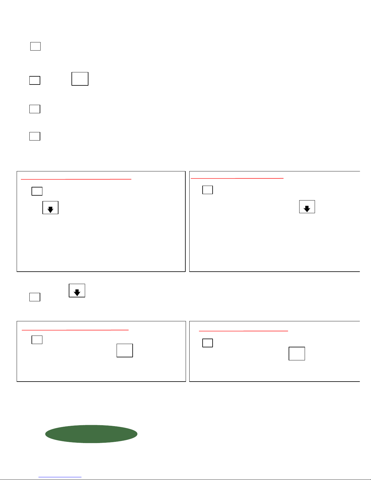
START-UP CHECK-OFF LIST
1
2
3
4
"PORTABLE" TANKS - Tank is REPLACED
POWER-UP: Scale display should read "NET WEIGHT REMAINING". The value will be the tare weight
of your SCALE PLATFORM(s) in "PORTABLE" Tank applications, or your VESSEL & PLATFORM in "FIXED" tank
applications.
Press and verify correct time and date. If incorrect, see SET-UP CODE 9087 (Section W.2.204).
Apply pressure to platform to see if indicator responds to changes in weight.
Review SET-UP CODES, especially 9082, 9084, 9085 and 9089 (Starting at Section W.2.201)
TIME
DATE
5
MENU
Press until "SET SCALE ZERO" appears
on display. Zero scale as per instructions in Section
W.2.106 "Menu of Day-To-Day Operations". For
future reference, record ZERO FACTOR on a
sticker inside Wizard cover. Refer to Section
W.2.204 "Custom Formatting your Scale",
CODE 9088, to obtain zero factor.
"FIXED" TANKS - Tank is REFILLED
5
MENU
With EMPTY tank on platform, press
until scale indicator reads "ENTER TARE". Zero scale as
per instructions in Section W.2.106 "Menu of Day-To-Day
Operations". For future reference, record ZERO FACTOR
on a sticker inside Wizard cover. Refer to Section W.2.204
"Custom Formatting your Scale", CODE 9088, to obtain
zero factor.
MENU
6
"PORTABLE" TANK - Tank is REPLACED
Press until "CLEAR AMOUNT USED" appears on display. Clear the memory per
instructions in Menu of Day-To-Day Operations (Section W.2.105).
7
TANK
Before LOADING Tank(s), press and wait
until Step 4 "CHANGE TANKS NOW" appears.
See instructions on Tank Load Mode Section W.2.103.
NOTE: If you load tank before reaching the "CHANGE TANK NOW" or the "FILL TANK NOW" step, your
usage data will be inaccurate.
FORCE FLOW
FORCE FLOW
FFLLOOQQIIUUP
QUESTIONS ? Help Hotline: 1-800-893-6723
LOAD
P
W.1.305
"FIXED" TANK - Tank is REFILLED
7
TANK
Before FILLING Tank(s), press and proceed
as directed. Refer to "Operating Instructions",
Section W.2.103 TANK LOAD MODE.
1150-D Burnett Ave, Concord, CA 94520 USA
1-800-893-6723 US & Canada, Fax: 925-686-6713
www.forceflow.com / [email protected]
File: T4\O&M\AWZMSTR\CHKOFF.tcw (J10.pdf) 01/24/02 BD
LOAD
Page 16
SECTION
INDEX
WIZARD Indicator with DRUMM-SCALE
W.1.000
W.2.000
YOU
ARE
HERE !
INSTALLATION OF SCALE PLATFORM:
W.1.101
W.1.102
Installation Instructions
Dimensional Drawing
INSTALLATION OF LOAD CELL
W.1.141
Load Cell Installation Drawing
INDICATOR INSTALLATION
W.1.201
W.1.202-203
W.1.204
Indicator Wiring & Plumbing
Indicator Installation Instructions
Wizard Component Layout
INSTALLATION CHECK OFF LISTS
W.1.301
W.1.305
Installation Check-Off List
Installation Start-Up Check-Off List
INDICATOR OPERATION
W.2.101
W.2.102
W.2.103
Keyboard Display Selections
Keyboard Menu - Quick Reference
Tank Load Mode
MEMU OF DAY-TO-DAY OPERATIONS
W.2.104
W.2.105
W.2.106
W.2.107
W.2.108
Low Level Alarm & Date Last Cleared
Clear Amount Used & Set Scale Zero
Set Scale Zero cont... & Allarm Reset
Review Daily Usage & Printing Report
Report (example) & Protocol
SET-UP CODES - CUSTOM FORMATTING
W.2.201
W.2.202
W.2.203
W.2.204
W.2.205
W.2.206
W.3.000
MISCELLANEOUS
W.3.101
W.3.201
W.3.301
W.3.401
FORCE FLOW
FORCE FLOW
FFLLOOQQIIUUP
P
Code 9080 (Scale Set Up)
Code 9082-9083 (Feed Rate Format/Display Units)
Code 9084-9086 (Single or Dual Display/Tank Loading/Printer)
Code 9086 (cont...)-9089 (Time/Date/Calibration/Channels)
Code 4200 & 3256 (Set Point Configuration/4-20mA Output Configuration)
Code 3256 (cont...)
Code 9081 (Field Calibration)
Checking Calibration via Water Test
Troubleshooting Tips
Spare Parts List
1150-D Burnett Ave, Concord, CA 94520 USA
1-800-893-6723 US & Canada, Fax: 925-686-6713
www.forceflow.com / [email protected]
REF: T4\O&M\INDEX.\Y07.tcw etc (Y07.pdf etc) 1/24/02
Page 17
WIZARD 4000
0
1
2
3
45678
9
SCALE
SELECT
DISPLAY
SELECT
TOTALS
TANK
LOAD
MENU
MENU
ENTER
AMOUNT USED
SCALE 1 = 7687 LB
SCALE 2 = 6521 LB
MENU
MENU
DEL
DEL
TANK
LOAD
SCALE
SELECT
ENTER
%
TOTALS
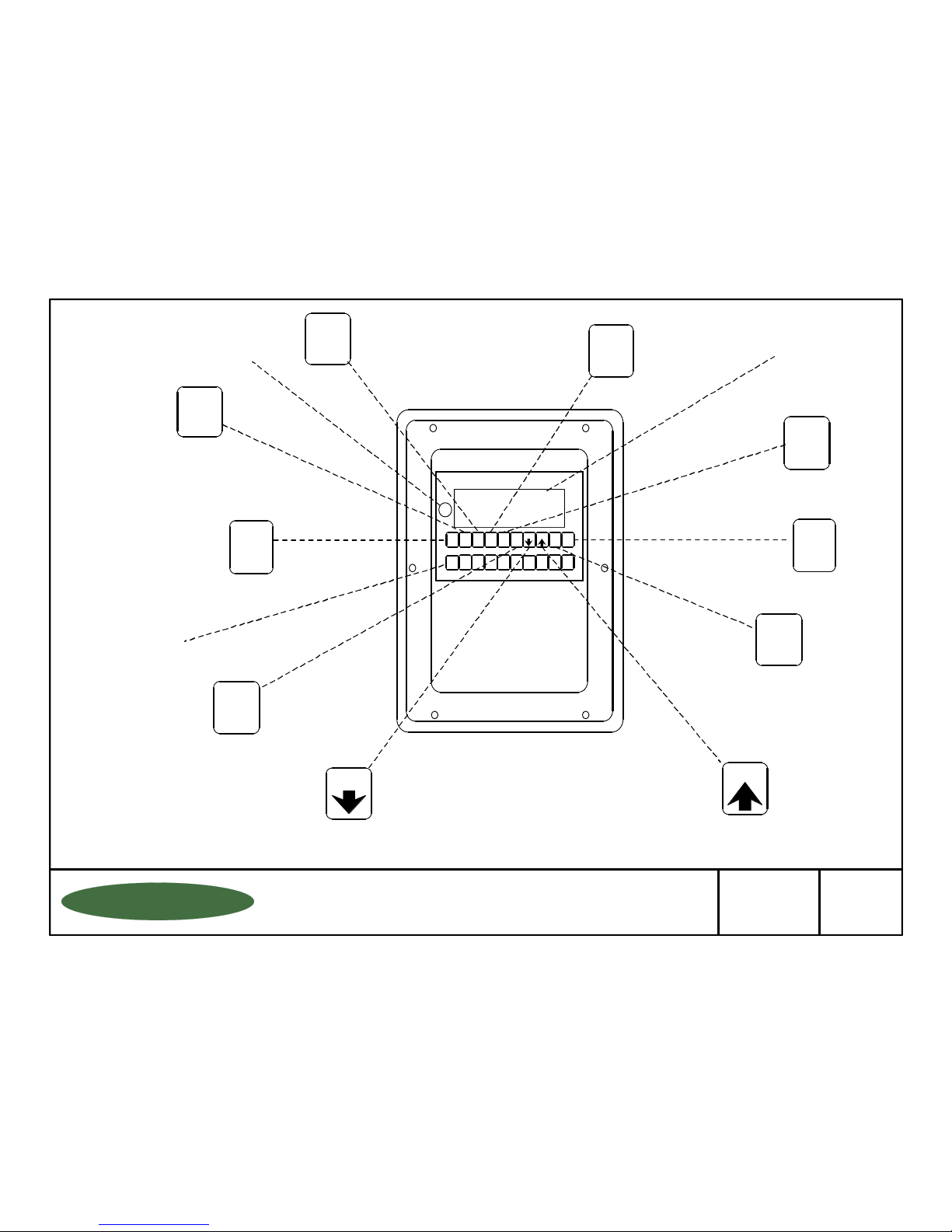
Toggles through a
multi-function display
for each scale.
Toggles through a
multi-function display
for the totals of all scales.
Toggles
Between
Individual
Scales
Scrolls
Back
Through
the Menu
OPERATIONS MENU
LOW LEVEL ALARM........................
DATE LAST CLEARED....................
CLEAR AMOUNT USED..................
SET SCALE ZERO/ENTER TARE..
ALARM RESET................................
REVIEW DAILY USE.......................
FUNCTION DESCRIPTION
Entering of low level setpoint
Date the "amount used" was last reset
Clears the "amount used" display
Zero's the display
Resets the low level alarm (if set in
the latching mode)
Reviews past 10 days usage
Backspace
or Escape
Menu Operations
Data Entry
and Menu
Function
Access
"Time" and
"Date"
Displays
Percent
of Full
Reset Button (Resets
screen to opening menu
in case of entry error)
Single or Dual
Display (16
Characters
per Line Screen)
Total Remaining
Total Used
Total Feed Rate
Net Remaining
Amount Used
Average Feed Rate
Days Until Empty
Daily Usage
If applicable:
Tare Weight
Gross Weight
Scrolls
Forward
Through
the Menu
Loading
New Tanks
or Chemicals
Numeric
Data Entry
Key Pad
DISPLAY
SELECT
TIME
DATE
TIME
DATE
%
1150-D Burnett Ave, Concord, CA 94520 USA
1-800-893-6723 US & Canada, Fax: 925-686-6713
www.forceflow.com / [email protected]
Drawn by: SLP
Date: 09/01/95
Revised: 11/01/99
Scale: NONE
Drawing Number
File: T4\O&M\AWZMSTR\WZBUTTON.tcw (B05.pdf) 10/20/99
29887
WIZ
INDICATOR BUTTON
FUNCTIONS LIST FOR
WIZARD INDICATOR
FORCE FLOW
FORCE FLOW
FFLLOOQQIIUUP
P
W.2.101
Page 18

KEYBOARD & MENU FUNCTIONS
QUICK REFERENCE GUIDE
These are the functions that are used on a day-to-day basis.
SCALE SELECT
DISPLAY SELECT
NET REMAINING............
AMOUNT USED..............
AVERAGE FEED RATE..
DAYS UNTIL EMPTY......
DAILY USAGE................
If applicable:
TARE WEIGHT...............
GROSS WEIGHT...........
TOTALS
TOTAL REMAINING.........
TOTAL USED...................
TOTAL FEED RATE.........
%
Scrolls forward through individual scales.
Toggles through a multi-function display for each scale in the
following decending order:
Chemical remaining in tank or cylinder
A running total of net chemical used since last reset
Current chemical feed rate in lbs. or gallons per day
Days until empty at the current feed rate
Previous day's total chemical usage
Tank tare weight
Tank tare plus chemical weight
Toggles through a multi-function display for the totals of all scales,
in the following descending order:
Chemical remaining in all tanks
Chemical used in all tanks
Chemical feed rate of all tanks
Displays NET REMAINING as a PERCENTAGE of full.
TIME DATE
TANK LOAD
MENU DOWN
Time and Date
Loading new tanks or chemicals and entering tank tare weights.
Scroll through a list of day-to-day operations in DESCENDING order.
See Section "OPERATING INSTRUCTIONS", under
"MENU OF DAY-TO-DAY OPERATIONS":
LOW LEVEL ALARM...........
DATE LAST CLEARED.......
CLEAR AMOUNT USED.....
SET SCALE ZERO/TARE...
ALARM RESET...................
REVIEW DAILY USE..........
PRINT.................................
FORCE FLOW
FORCE FLOW
FFLLOOQQIIUUP
QUESTIONS ? Help Hotline: 1-800-893-6723
P
Entering of low level set point values
Date the "amount used" display was last cleared
Clears the "amount used" display and "daily usage" display
Zero's the display
Resetsthe low level alarm (if set in the latching mode)
Stores the last 10 days Daily Usage
Outputs date via serial port to a printer
1150-D Burnett Ave, Concord, CA 94520 USA
1-800-893-6723 US & Canada, Fax: 925-686-6713
www.forceflow.com / [email protected]
W.2.102
File: T4\O&M\AWZMSTR\WZKEYBD2.tcw (B06.pdf) 10/20/99
Page 19
TANK LOAD MODE
It also allows you to enter the tare weight(s) of your tanks if you choose "Manual" tank load mode, or load the
net weight of a cylinder if you chose the "Auto" tank load mode. (See Code Set-up 9085)
WARNING !
DO NOT UNLOAD or LOAD tanks until "CHANGE TANKS NOW, THEN
PRESS ENTER" appears on the display. If you load or unload tanks
before reaching this step, the "amount used" and "daily usage" displays
will be incorrect.
TANK
LOAD
Allows you to load new tanks without adversly affecting
the "AMOUNT USED" and "DAILY USAGE" displays.
Step 1
Step 2
Digital Display
NET REMAINING
SCALE 1 = XXXX
ENTER SCALE #
1 THRU 2 X
Action Required - Press "ENTER" after completing each step.
Press to enter the tank load mode.
Press or then
Enter the scale NUMBER that you want to load/unload tanks.
This "freezes" or "holds" the AMOUNT USED and DAILY
USAGE displays until feeding resumes).
TANK
LOAD
1
Skip to STEP 7 in "FIXED" Tank Applications.
"PORTABLE" Tank Applications (Follow Steps 1 thru 6 only)
(such as Ton Containers, Drums and Cylinders)
Step 3
TARE MODE
*AUTO MANUAL
Press to select which method, then press
Use "MANUAL" for PARTIALLY FULL containers.
Use "AUTO" for FULL containers.
MENU
....If you chose "MANUAL" you will manually enter tank
tare weight in Step 6.
....If you chose "AUTO" the WIZARD automatically loads the
net weight and goes into the weighing mode (skip Step 6).
2
ENTER
ENTER
Step 4
CHANGE TANKS NOW
THEN PRESS ENTER
Step 5
....If MANUAL chosen above in Step 3...
Step 6
WAIT
SCALE #2 TANK #1
TARE = XXXX
"FIXED" Tank Applications (Follow Steps 1, 2 and 7 only)
(such as Chem-Scale, Hoppers, Powercells and Ultrasonic)
Step 7
FORCE FLOW
FORCE FLOW
FFLLOOQQIIUUP
QUESTIONS ? Help Hotline: 1-800-893-6723
FILL TANK NOW
THEN PRESS ENTER
P
Remove empty tanks and place new tank(s) onto the scale
then press
Wait until this clears to continue.
MANUAL Mode: Requires that you enter tare weight of EACH tank on
EACH scale. (Example: Scale #2, tare weight of TANK #1, then
TANK #2, etc). After entering the tare weights of all your tanks, the
WIZARD 4000 automatically adds them up and subtracts them from
the gross weight.
Fill your tank with chemicals, then press
W.2.103
ENTER
ENTER
1150-D Burnett Ave, Concord, CA 94520 USA
1-800-893-6723 US & Canada, Fax: 925-686-6713
www.forceflow.com / [email protected]
File: T4\O&M\AWZMSTR\WZDAY1B.tcw 11/99 (B07.pdf)
Page 20
SECTION
INDEX
WIZARD Indicator with DRUMM-SCALE
W.1.000
W.2.000
YOU
ARE
HERE !
INSTALLATION OF SCALE PLATFORM:
W.1.101
W.1.102
Installation Instructions
Dimensional Drawing
INSTALLATION OF LOAD CELL
W.1.141
Load Cell Installation Drawing
INDICATOR INSTALLATION
W.1.201
W.1.202-203
W.1.204
Indicator Wiring & Plumbing
Indicator Installation Instructions
Wizard Component Layout
INSTALLATION CHECK OFF LISTS
W.1.301
W.1.305
Installation Check-Off List
Installation Start-Up Check-Off List
INDICATOR OPERATION
W.2.101
W.2.102
W.2.103
Keyboard Display Selections
Keyboard Menu - Quick Reference
Tank Load Mode
MEMU OF DAY-TO-DAY OPERATIONS
W.2.104
W.2.105
W.2.106
W.2.107
W.2.108
Low Level Alarm & Date Last Cleared
Clear Amount Used & Set Scale Zero
Set Scale Zero cont... & Allarm Reset
Review Daily Usage & Printing Report
Report (example) & Protocol
SET-UP CODES - CUSTOM FORMATTING
W.2.201
W.2.202
W.2.203
W.2.204
W.2.205
W.2.206
W.3.000
MISCELLANEOUS
W.3.101
W.3.201
W.3.301
W.3.401
FORCE FLOW
FORCE FLOW
FFLLOOQQIIUUP
P
Code 9080 (Scale Set Up)
Code 9082-9083 (Feed Rate Format/Display Units)
Code 9084-9086 (Single or Dual Display/Tank Loading/Printer)
Code 9086 (cont...)-9089 (Time/Date/Calibration/Channels)
Code 4200 & 3256 (Set Point Configuration/4-20mA Output Configuration)
Code 3256 (cont...)
Code 9081 (Field Calibration)
Checking Calibration via Water Test
Troubleshooting Tips
Spare Parts List
1150-D Burnett Ave, Concord, CA 94520 USA
1-800-893-6723 US & Canada, Fax: 925-686-6713
www.forceflow.com / [email protected]
REF: T4\O&M\INDEX.\Y07.tcw etc (Y07.pdf etc) 1/24/02
Page 21
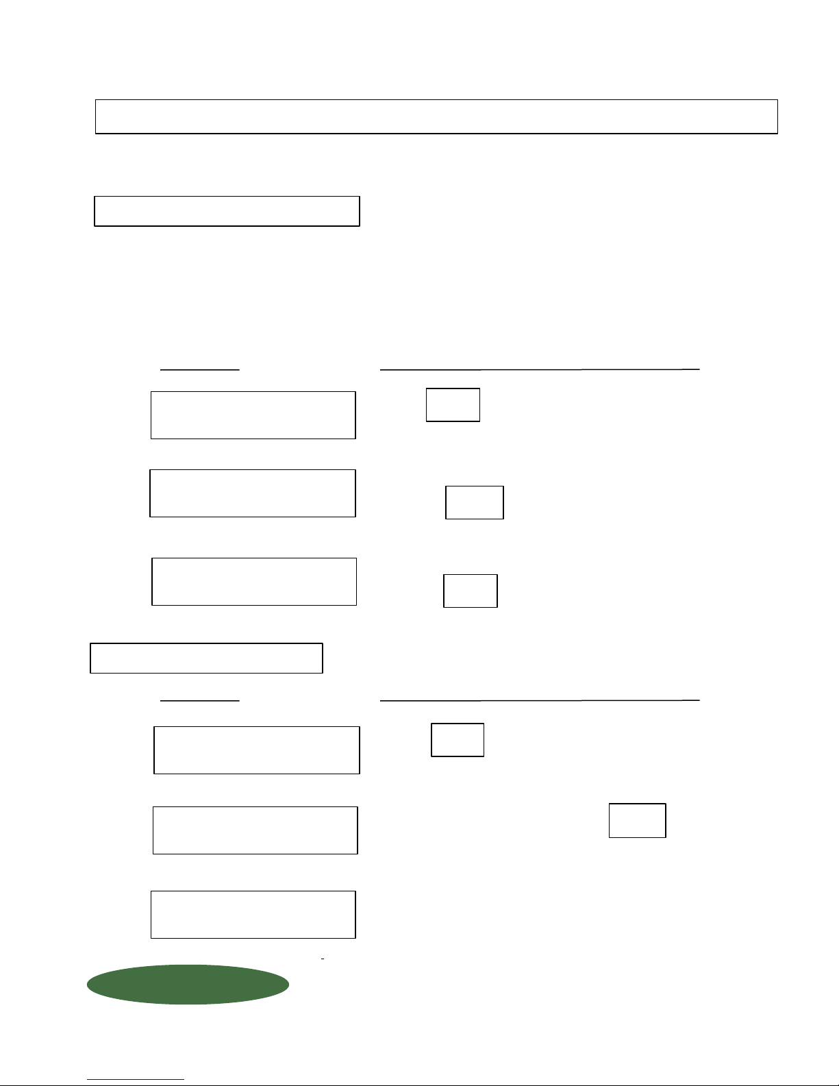
MENU OF DAY-TO-DAY OPERATIONS
This menu contains a list of operations that are used on a frequent basis. Each menu item is followed by
"THEN PRESS ENTER" and has step-by-step operating instructions.
LOW LEVEL ALARM
Allows you to enter your low level set point values for the optional low level alarm. For this function to work properly,
the alarm must be "enabled" under the Set-up Code #4200. Be sure to read this set-up code thoroughly before
using this function. When a low level condition exists, your display will continuously flash "Low Level Scale #_____"
and the optional 5 AMP relay will be activated. (See Chapter "SET-UP CODES")
NOTE: You must have purchased the low level alarm option and your alarm must be
enabled under Code Set-Up #4200 for this function to operate. (See Chapter "SET-UP CODES")
Digital Display
Step 1
LOW LEVEL ALARM
THEN PRESS ENTER
Step 2
LOW LEVEL ALARM
SCALE 1 = X LB.
Step 3
LOW LEVEL ALARM
SCALE 2 = X LB.
DATE LAST CLEARED
Digital Display
Step 1
DATE LAST CLEARED
THEN PRESS ENTER
Action Required - Press "ENTER" after completing each step.
Press to continue.
Enter low level VALUE via key pad for SCALE 1...
then press (Example: Low level set point 100 lbs)
Enter low level VALUE via key pad for SCALE 2...
then press (Example: Low level set point 150 lbs)
This function allows the user to find out the last time and date the
"Amount Used" display was cleared or reset for each scale.
Action Required - Press "ENTER" after completing each step.
Press to continue.
ENTER
ENTER
ENTER
ENTER
Step 2
ENTER SCALE #
1 THRU 2 X
(or 1 thru 4)
Step 3
SCALE 2 CLEARED
09/15/95 22:15
FORCE FLOW
FORCE FLOW
FFLLOOQQIIUUP
QUESTIONS ? Help Hotline: 1-800-893-6723
P
Enter which scale NUMBER... then press
Displays DATE and TIME "AMOUNT USED" function was last
cleared is displayed for 8 seconds
1150-D Burnett Ave, Concord, CA 94520 USA
1-800-893-6723 US & Canada, Fax: 925-686-6713
www.forceflow.com / [email protected]
W.2.104
File: T4\O&M\AWZMSTR\WZDAY2.tcw (B08.pdf)
ENTER
Page 22
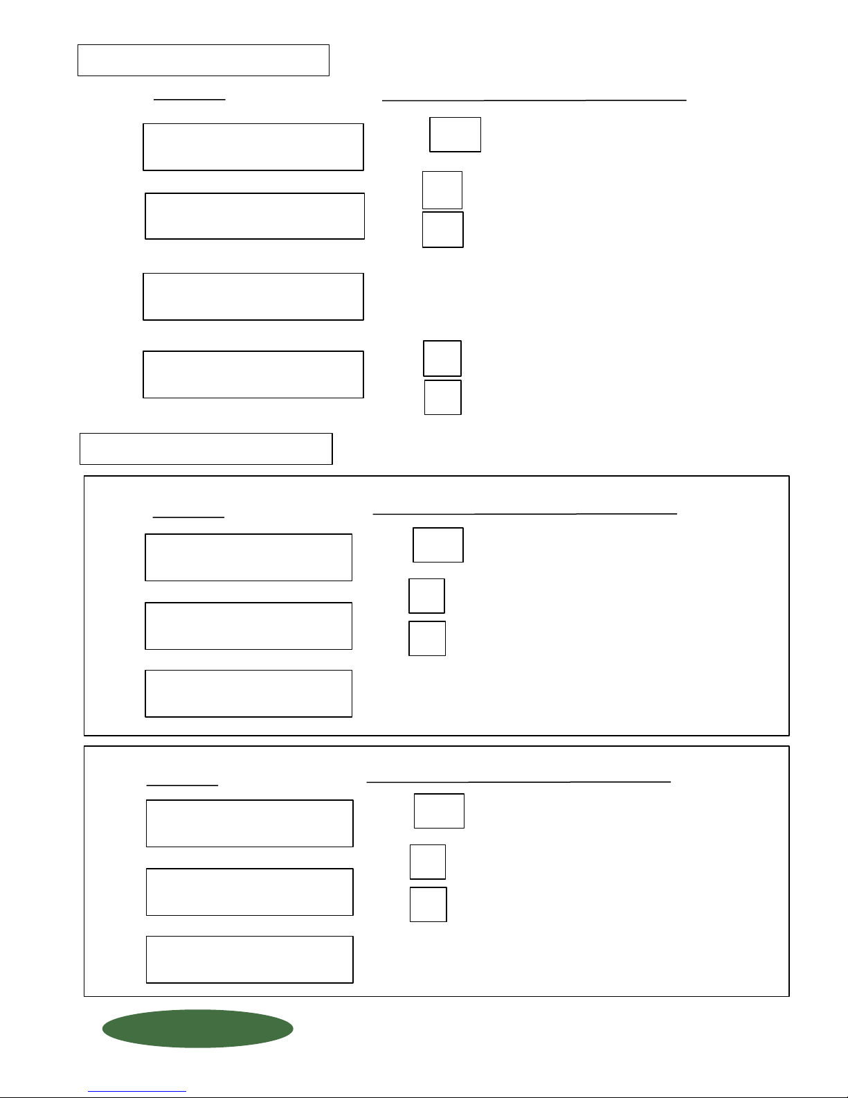
CLEAR AMOUNT USED
Clears or resets the "AMOUNT USED" and
"DAILY USAGE" display to zero.
Digital Display
Step 1
CLEAR AMOUNT USED
THEN PRESS ENTER
Step 2
CLEAR ALL SCALES
1 = Y 0 = N X
Step 3
ENTER SCALE #
1 THRU 4 X
Step 4
ARE YOU SURE?
1 = Y 0 = N X
SET SCALE ZERO / TARE
Allows the user re-zero the display if it has drifted or changed, OR enter
the TARE WEIGHT of the tank.
PORTABLE TANK APPLICATIONS . . . .
Digital Display
Action Required - Press "ENTER" after completing each step.
Press to continue.
Enter to clear all scales....or (if "1" entered, skip Step 3)
Enter to clear individual scales (go to Step 3)
If you chose INDIVIDUAL scales....
Enter the NUMBER of the scale you want to enter a Tare Weight.
Choose scale 1, 2, 3 or 4
Enter for YES...
Enter for NO
Action Required - Press "ENTER" after completing each step.
ENTER
1
0
1
0
Step 1
SET SCALE ZERO
THEN PRESS ENTER
Step 2
ARE YOU SURE?
1 = Y 0 = N X
Step 3
ENTER SCALE #
1 THRU 4 X
FIXED TANK APPLICATIONS . . . . .
Digital Display
Step 1
ZERO / TARE
THEN PRESS ENTER
Step 2
ARE YOU SURE?
1 = Y 0 = N X
Press to continue.
ENTER
Enter for YES....or
Enter for NO
1
0
Enter the NUMBER of the scale you want to enter a Tare Weight.
Choose scale 1, 2, 3 or 4
Action Required - Press "ENTER" after completing each step.
Press to continue.
ENTER
Enter for YES....or
Enter for NO
1
0
Step 3
ENTER SCALE #
1 THRU 4 X
FORCE FLOW
FORCE FLOW
FFLLOOQQIIUUP
QUESTIONS ? Help Hotline: 1-800-893-6723
P
Enter the NUMBER of the scale you want to enter a Tare Weight.
Choose scale 1, 2, 3 or 4
1150-D Burnett Ave, Concord, CA 94520 USA
1-800-893-6723 US & Canada, Fax: 925-686-6713
www.forceflow.com / [email protected]
W.2.105
File: T4\O&M\AWZMSTR\WZDAY3A.tcw 06/01/99 (B09.pdf)
Page 23
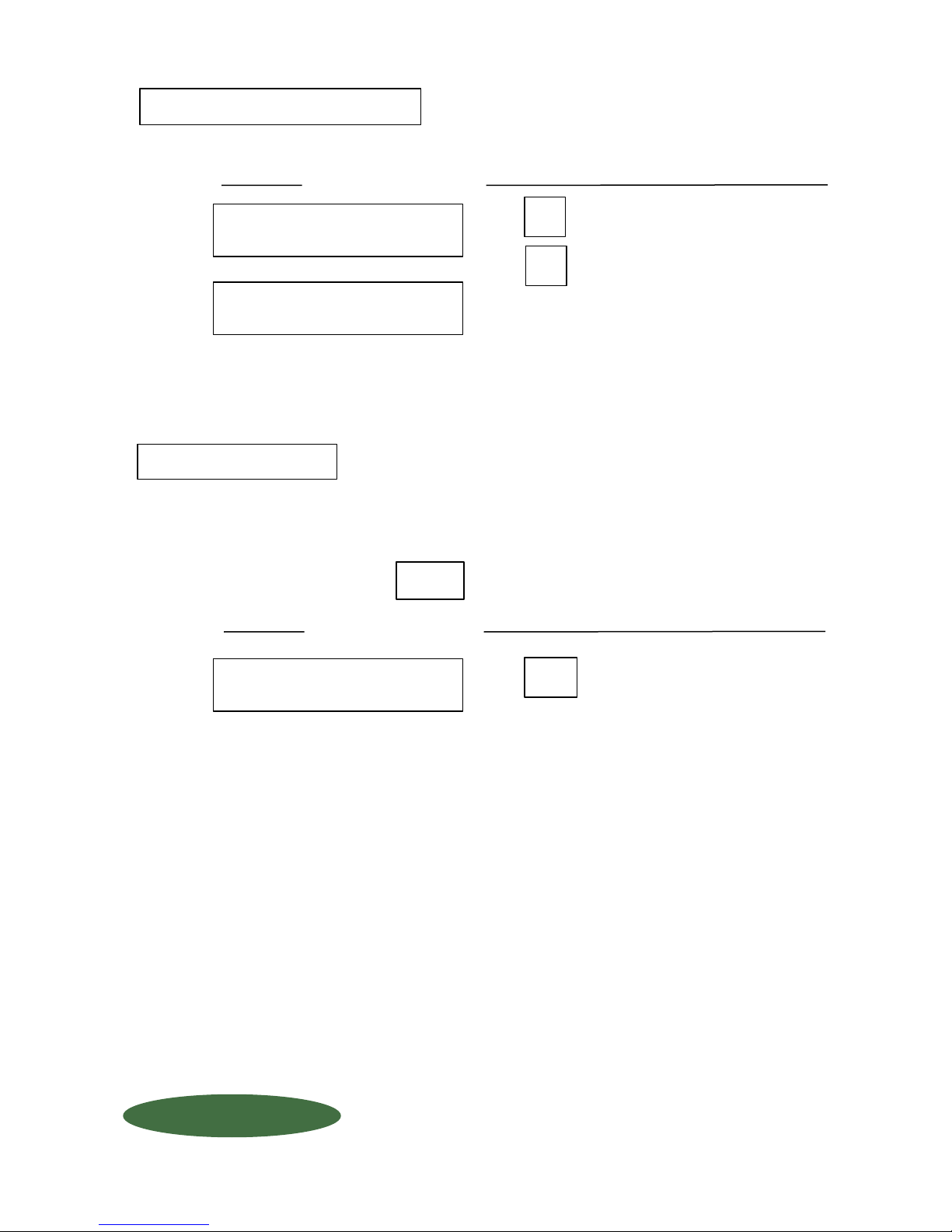
SET SCALE ZERO / TARE
FIXED TANK APPLICATIONS cont . . . .
Continued . . .
Digital Display
Step 4
IS TANK EMPTY ?
1 = Y O = N
Step 5
ENTER TANK
TARE = XXXX
ALARM RESET
Re-sets the optional low level alarm, if your alarm is set in the latching mode.
Digital Display
Action Required - Press "ENTER" after completing each step.
Enter for YES....or
Enter for NO
1
0
Using the Numeric Keys, input the TARE WEIGHT
(the weight of the empty tank and any other accessories)
NOTE: You must correct the low level condition (choose the applicable remedy):
Replace the CL2 or SO2 tank(s)
Fill the tank
before resetting the alarm. Silence the optional internal audible alarm by
pressing
Portable Tank:
Stationary Tank/Hopper:
DELETE
Action Required - Press "ENTER" after completing each step.
Step 1
ALARM RESET
THEN PRESS ENTER
FORCE FLOW
FORCE FLOW
FFLLOOQQIIUUP
QUESTIONS ? Help Hotline: 1-800-893-6723
P
Press to reset.
ENTER
W.2.106
1150-D Burnett Ave, Concord, CA 94520 USA
1-800-893-6723 US & Canada, Fax: 925-686-6713
www.forceflow.com / [email protected]
File: T4\O&M\AWZMSTR\WZDAY3B.tcw 11/99 (B10.pdf)
Page 24
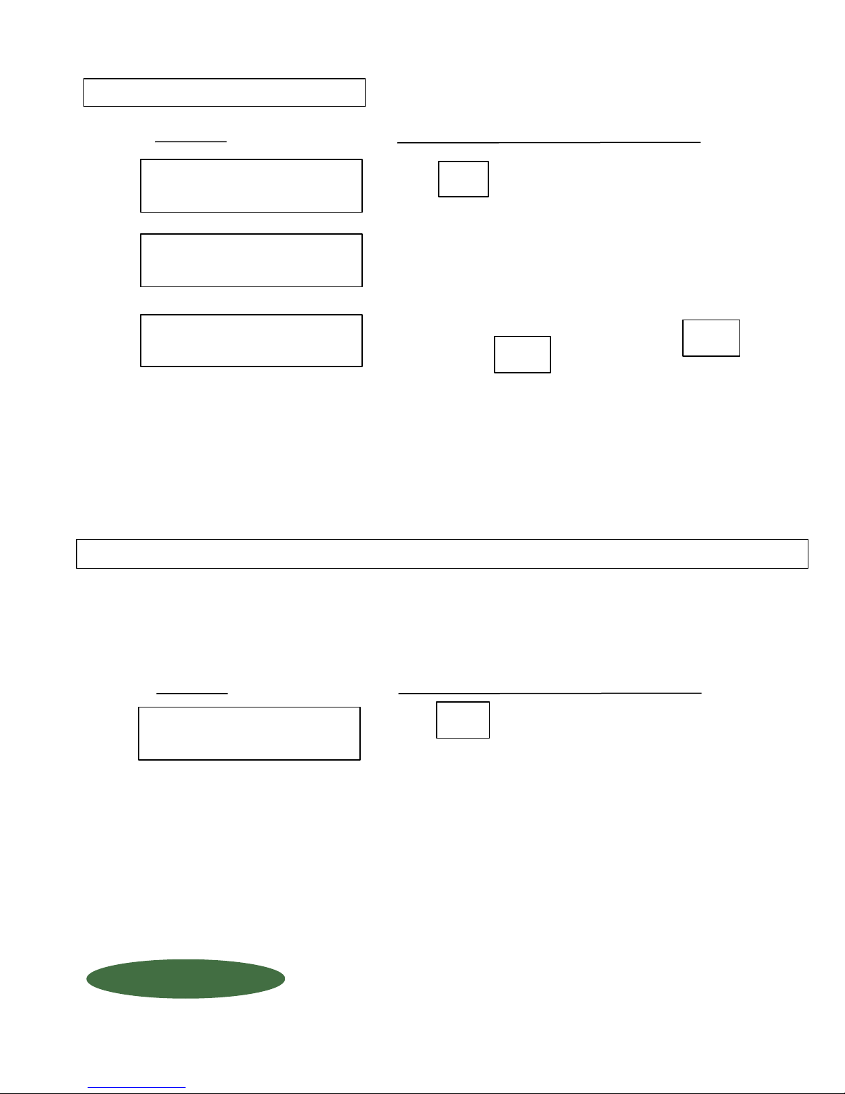
REVIEW DAILY USAGE
Allows the user to review past 10 days chemical usage.
Step 1
Step 2
Step 3
Digital Display
REVIEW DAILY USAGE
THEN PRESS ENTER
ENTER SCALE #
1 THRU 2 XXXX
SCALE 1 USAGE;
12/25/96 164
Action Required - Press "ENTER" after completing each step.
Press to continue.
Enter the number of the scale you want to review.
Chemical usage on that particular date. Press
for next date, or to escape.
ENTER
ENTER
DELETE
PRINT
The print function allows you to down load display functions to a printer or other aparatus on a
manual or automatic basis. If you chose "Auto Print" under Code Set-Up 9086, the entire report will be printed.
Step 1
Digital Display
PRINT
Action Required - Press "ENTER" after completing each step.
Press to continue.
ENTER
PRESS ENTER
FORCE FLOW
FORCE FLOW
FFLLOOQQIIUUP
QUESTIONS ? Help Hotline: 1-800-893-6723
P
W.2.107
1150-D Burnett Ave, Concord, CA 94520 USA
1-800-893-6723 US & Canada, Fax: 925-686-6713
www.forceflow.com / [email protected]
File: T4\O&M\AWZMSTR\WZDAY4A.tcw 11/99 (B11.pdf)
Page 25

REPORT (example of "REPORT")
Ready . . .
8/ 15/ 0 14:21
Net Chemical Remaining......
in the Tank
NET REMAINING
SCALE 1 1950 LB
SCALE 1832 LB
--------------------TOTAL = 3782 LB
AVG FEED RATE
SCALE 1 0 PD
SCALE 2 288 PD
---------------------TOTAL = 288 PD
PROTOCOL
Protocol for other communication devices.
Baud Rate: 600, 1200, 2400, 4800 or 9600
Bits: 8 Bit, 1 Start Bit, 1 Stop Bit, No Parity
Hand Shake: None
.....................Time and Date of Report
................Average Chemical Feed
Rate in Lbs/Days or Lbs/Hr
FORCE FLOW
FORCE FLOW
FFLLOOQQIIUUP
QUESTIONS ? Help Hotline: 1-800-893-6723
P
W.2.108
1150-D Burnett Ave, Concord, CA 94520 USA
1-800-893-6723 US & Canada, Fax: 925-686-6713
www.forceflow.com / [email protected]
File: T4\O&M\AWZMSTR\WZPRINTA.tcw 10/20/99 (B12.pdf)
Page 26
SECTION
INDEX
WIZARD Indicator with DRUMM-SCALE
W.1.000
W.2.000
INSTALLATION OF SCALE PLATFORM:
W.1.101
W.1.102
Installation Instructions
Dimensional Drawing
INSTALLATION OF LOAD CELL
W.1.141
Load Cell Installation Drawing
INDICATOR INSTALLATION
W.1.201
W.1.202-203
W.1.204
Indicator Wiring & Plumbing
Indicator Installation Instructions
Wizard Component Layout
INSTALLATION CHECK OFF LISTS
W.1.301
W.1.305
Installation Check-Off List
Installation Start-Up Check-Off List
INDICATOR OPERATION
W.2.101
W.2.102
W.2.103
Keyboard Display Selections
Keyboard Menu - Quick Reference
Tank Load Mode
MEMU OF DAY-TO-DAY OPERATIONS
W.2.104
W.2.105
W.2.106
W.2.107
W.2.108
Low Level Alarm & Date Last Cleared
Clear Amount Used & Set Scale Zero
Set Scale Zero cont... & Allarm Reset
Review Daily Usage & Printing Report
Report (example) & Protocol
SET-UP CODES - CUSTOM FORMATTING
YOU
ARE
HERE !
W.2.201
W.2.202
W.2.203
W.2.204
W.2.205
W.2.206
W.3.000
MISCELLANEOUS
W.3.101
W.3.201
W.3.301
W.3.401
FORCE FLOW
FORCE FLOW
FFLLOOQQIIUUP
P
Code 9080 (Scale Set Up)
Code 9082-9083 (Feed Rate Format/Display Units)
Code 9084-9086 (Single or Dual Display/Tank Loading/Printer)
Code 9086 (cont...)-9089 (Time/Date/Calibration/Channels)
Code 4200 & 3256 (Set Point Configuration/4-20mA Output Configuration)
Code 3256 (cont...)
Code 9081 (Field Calibration)
Checking Calibration via Water Test
Troubleshooting Tips
Spare Parts List
1150-D Burnett Ave, Concord, CA 94520 USA
1-800-893-6723 US & Canada, Fax: 925-686-6713
www.forceflow.com / [email protected]
REF: T4\O&M\INDEX.\Y07.tcw etc (Y07.pdf etc) 1/24/02
Page 27
SET-UP CODES
Model Number of Scale/Sensor: ___________
Quantity of Scale Platforms: ________ (if applicable)
These Set-Up Codes allow you to custom format your scale for your specific application. They may be accessed when
initially installing your scale, but otherwise, very infrequently. You may change your default setting by entering the
4-digit numeric password and then pressing "ENTER". You may NOT access Set-Up codes while in the "MENU". You
must press delete to escape the Menu.
NOTE:
All Set-Up Codes have been factory set for your specific application and your
scale(s) has been calibrated.
9080 SCALE SET-UP
This function allows you to format your display by choosing various parameters like "lbs" or "kilos"; how many fixed zeros;
number of decimal places; your increments or "county by"; total number of digits or "resolution", and your capacity.
NOTE:
Digital Display / Default (in red)
WEIGHT UNITS
*LBS or KGS _______
NUMBER OF
DECIMALS _______
FIXED ZEROS ______
If any of the scale Set-Up functions are changed, your scale must be recalibrated.
Action Required - Press "ENTER" after completing each step
Choose to read either "metric" or "imperial" units. Use arrow keys to select.
How many numbers right of the decimal point. Enter "O" or "1"
Example: 1 decimal place = 486.3 pounds.
NOTE: Most applications over 2,000 lbs. will use "O" decimal places.
This function is displayed only if "0" decimal places is selected. This
represents how many "dead" zeros you want on your display. Enter "0" or "1".
Example: 1 fixed zero = 26,340
1, 2, OR 5
COUNT BY _______
RESOLUTION
DIGITS = ________
CAPACITY _________
BY _________
FORCE FLOW
FORCE FLOW
FFLLOOQQIIUUP
QUESTIONS ? Help Hotline: 1-800-893-6723
P
NOTE: Most applications under 20,000 lbs. will have "0" fixed zeros.
Establishes the minimum increments of the display. Enter "1", "2" or "5".
Example: "1" = 1 lb. increments. "5" = 5 lb. increments. Choose 1, 2 or 5.
Establishes the number of displayed increments or total "counts".
Choices: 1,000, 2,000, 3,000, 4,000, 8,000 or 12,000. Scroll the Menu Keys
until the desired resolution displays, then press ENTER.
NOTE: This number is not the total "capacity". Capacity will be the
automatic result of the "count by" and "resolution" entry.
Displays the result of the above selections. Push ENTER to accept.
1150-D Burnett Ave, Concord, CA 94520 USA
1-800-893-6723 US & Canada, Fax: 925-686-6713
www.forceflow.com / [email protected]
W.2.201
File: T4\O&M\AWZMSTR\WZSETUP1.tcw (B13.pdf)
Page 28
9081 FIELD CALIBRATION
(See Chapter "FIELD CALIBRATION, SET-UP CODE 9081")
9082 FEED RATE FORMAT
Allows you to choose between "lbs per day" ("gallons per day") and "lbs. per hour" ("gallons per hour") and allows you
to set your sample time or "update period" for your feed rate function.
*IMPORTANT NOTE: Setting your "Update Period"
In general, if your feed rates are fairly constant on a daily basis, the longer you set your update period for, the more
accurate your feed rate function will be. However, if your feed rate varies from hour to hour or minute to mintue, choose
a shorter update period to give you a more accurate feed rate at a point in time. You may have to experiment with
different update periods to get the desired result for your application.
HIGH FEED
FLUCTUATING
CONSTANT
Use a Short
Update Period
Use a Short or
Long Update Period
For certain applications with very low feed rates (less than 2% of full scale capacity per day), low sample times will not
give you accurate readings.
LOW FEED (less than 2% capacity/day)
N/A (Not Accurate)
Use a Longer
Update Period
Digital Display / Default (in red)
RATE TIME BASE
____PPH ____ PPD
____KPH ____ KPD
Action Required - Press "ENTER" after completing each step
Use ARROWS to select: (If Lbs chosen) (If Kgs chosen)
If calibrated in LBS/KGS: PPH = Lbs. per HOUR KPH = Kgs. per HOUR
PPD = Lbs. per DAY KPD = Kgs. per DAY
Or if calibrated in GALLONS: GPH = Gallons per HOUR
GPD = Gallons per DAY
PERIOD BASE
____MIN ____ HOUR
Use ARROWS to select:
Rate Update Period In: MIN = Minutes
HOUR = Hours
UPDATE PERIOD
HOURS = _________
Use ARROWS to select update period:
Choice if HOURS: 2, 4, 6, 8, 12 Hours
Choice if MINUTES: 2, 5, 10, 20, 30, 60 Minutes
NOTE: See IMPORTANT NOTE above "Setting your Update Period".
9083 DISPLAY UNITS
This function allows you to choose your display to read in weight or gallons. If you choose gallons, you must enter
the specific gravity of the chemical being fed.
Digital Display / Default (in red)
DISPLAY UNITS
*LBS. GAL
*KGS GAL
Action Required - Press "ENTER" after completing each step
Use ARROWS to select WEIGHT (Lbs/Kgs) or VOLUME (Gallons).
SPECIFIC GRAVITY
SCALE 1 = X.XXX
NET REMAINING
SCALE 1 = X.XXX
FORCE FLOW
FORCE FLOW
FFLLOOQQIIUUP
QUESTIONS ? Help Hotline: 1-800-893-6723
P
If you choose VOLUME, enter the specific gravity of material being fed.
Displays the result of the above selections.
1150-D Burnett Ave, Concord, CA 94520 USA
W.2.202
1-800-893-6723 US & Canada, Fax: 925-686-6713
www.forceflow.com / [email protected]
File: T4\O&M\AWZMSTR\WZSETUP2.tcw (B14.pdf)
Page 29
9084 SINGLE or DUAL DISPLAY
Allows display to alternate between scale displays automatically or manually as well as displaying 1 or 2 scales at a time.
Digital Display / Default (in red)
Action Required - Press "ENTER" after completing each step
AUTO SCAN ?
1=Y 0=N
Do you want the sceen to automatically alternate between diplays?
Choices: "1" = YES "0" = NO
Use ARROW KEY to select:
DISPLAY FORMAT
*SINGLE DUAL
SINGLE = 1 scale displayed
DUAL = 2 scales displayed
NOTE: Single channel scale CANNOT Auto Scan and will only use
single scale display.
9085 TANK LOADING MODE
Cl2 & SO2
For applications: This allows the user to either manually enter tank tare weights, or to automatically
load full containers of 2,000 lbs.net weight. However, if container is partially empty, or if you are only loading one
tank on a multiple tank scale, you must use "MANUAL" mode.
For applications: You must use "MANUAL" mode.
ALL OTHER CHEMICAL FEED, HOPPER & TANK
Digital Display / Default (in red)
TARE MODE
___AUTO ___MANUAL
AUTO NET WT / LB (/KG)
WEIGHT = _______
100% / AUTO LOAD
SCALE 1 XXX
Action Required - Press "ENTER" after completing each step
Use ARROW KEY to select:
Automatically load the net contents of containers
AUTO =
Manually enter the tare weight of your tanks.
MANUAL =
NOTE: "AUTO" applies to CL2 & SO2 tanks only
(and on some Drumm-Scale applications)
Will be displayed if AUTO was chosen above.
Use key pad to enter the net contents of containers.
NET WEIGHT EXAMPLES
2000 lb. = Ton Containers (USA)
150 lb. = 150 lb. Cylinders (USA)
907 kg. = Canadian Ton Containers
1000 kg. = Metric Ton Containers
Enter the value that represents a full tank.
9086 FORMAT PRINTER PORT (RS232 / RS485)
Allows you to format your communications baud rate; print format and whether you want to engage the
datalogging (auto print) function.
Digital Display / Default (in red)
USE DEL , ENTER
BAUD = ______
TOP LINE FEEDS
NUMBER = ______
BTM LINE FEEDS
NUMBER = ______
FORCE FLOW
FORCE FLOW
FFLLOOQQIIUUP
QUESTIONS ? Help Hotline: 1-800-893-6723
P
Action Required - Press "ENTER" after completing each step
Use ARROW KEY to select your BAUD RATE:
Choices: 300, 600, 1200, 2400, 4800, 9600.
Enter the number of SPACES at the TOP of your printout.
Choices: 1 to 100
Enter the number of SPACES at the BOTTOM fo your printout.
Choices: 1 to 100.
1150-D Burnett Ave, Concord, CA 94520 USA
1-800-893-6723 US & Canada, Fax: 925-686-6713
W.2.203
File: T4\O&M\AWZMSTR\WZSET3C.tcw 11/99 (B15.pdf)
www.forceflow.com / [email protected]
Page 30
.
.
.
.
i
n
R
T
(
A
D
C
W
a
R
c
n
t
i
o
o
y
h
o
i
I
Z
A
n
d
O
E
P
6
9
0
8
D
i
g
i
t
A
1
R
F
O
f
D
i
a
l
T
U
=
a
/
l
a
s
y
D
p
e
P
O
R
Y
0
)
u
l
t
(
r
i
e
n
d
T
N
?
I
N
=
R
P
T
A
M
R
I
N
T
_
_
_
_
_
a
"
P
r
e
i
q
r
R
-
e
u
e
d
t
o
u
c
e
R
t
o
t
o
w
a
n
t
=
s
:
1
"
"
0
D
4
0
0
a
a
l
s
o
n
R
s
s
E
T
"
E
N
g
e
e
Y
w
n
n
g
a
0
"
E
S
t
o
m
i
l
l
a
u
l
y
o
h
o
u
r
)
c
4
8
S
5
R
2
3
S
2
/
u
n
o
t
p
m
l
e
f
t
t
h
"
t
e
r
c
o
U
T
e
A
O
(
=
N
a
l
l
y
a
t
i
c
l
y
b
r
d
a
i
.
e
d
s
h
t
e
i
n
g
O
b
d
a
p
e
a
c
o
n
g
)
f
t
a
l
o
I
N
T
P
y
o
s
(
R
n
g
a
g
i
e
n
l
o
a
d
w
.
i
s
)
g
D
a
t
h
i
s
n
g
d
i
s
p
a
l
l
u
g
i
n
t
i
o
n
f
u
n
c
f
u
n
c
l
a
y
?
n
c
t
i
,
t
h
e
s
t
i
o
n
l
e
i
l
l
w
s
A
f
B
f
e
T
N
T
I
I
a
H
E
a
1
M
_
_
_
A
D
D
N
d
a
t
e
)
l
t
u
(
i
n
r
e
d
X
X
X
X
X
X
X
X
X
X
T
I
O
A
R
v
u
=
a
e
r
i
f
y
C
)
l
t
(
i
n
r
e
d
F
X
S
,
"
y
o
I
f
Y
'
E
U
A
_
_
_
7
9
9
0
8
t
S
e
t
s
D
D
i
g
i
t
a
l
8
0
8
A
l
l
o
w
D
D
i
g
i
t
a
l
S
C
U
N
u
P
O
R
T
R
U
O
H
E
T
I
M
d
e
i
m
a
n
i
/
l
a
s
y
D
p
e
R
Y
E
A
T
O
N
M
D
A
Y
R
H
O
U
T
M
I
N
U
L
I
A
C
s
y
o
u
t
o
i
s
p
/
l
a
y
D
e
L
E
A
E
B
R
M
l
t
h
e
f
o
E
Y
A
D
E
T
C
A
F
N
n
l
i
b
r
a
t
i
o
T
C
O
A
X
X
X
X
:
g
o
i
n
w
o
r
U
R
c
t
o
r
n
f
a
t
o
r
e
r
e
s
u
e
.
v
a
l
T
R
e
r
H
o
n
c
I
N
T
I
U
T
O
s
e
l
e
c
t
K
E
Y
t
A
R
R
O
U
s
e
o
n
c
e
A
c
t
i
o
n
E
n
t
e
E
n
t
e
E
n
t
e
E
n
t
e
E
n
t
e
R
O
r
a
g
F
a
X
a
c
t
o
A
c
n
t
i
o
T
h
e
r
e
c
o
o
r
i
g
W
R
r
r
r
r
r
i
n
n
r
i
n
Y
p
e
r
D
A
i
q
r
e
u
e
d
-
t
h
e
Y
E
t
h
e
M
O
t
h
e
D
A
t
h
e
H
O
t
h
e
I
M
t
o
r
i
g
i
n
s
i
q
r
R
e
u
e
d
-
u
m
b
e
r
d
e
d
o
n
a
l
f
a
c
t
o
o
.
P
r
e
T
s
N
s
E
"
A
R
(
l
a
s
N
T
H
(
2
Y
(
2
d
i
g
U
R
i
(
m
U
T
E
(
N
l
f
a
c
t
o
a
s
r
s
e
E
P
T
"
N
d
i
s
p
l
a
y
t
h
e
c
a
l
i
r
y
v
a
l
u
e
a
"
f
R
t
e
r
c
E
2
d
i
g
i
t
t
d
i
g
i
t
s
.
i
t
s
.
E
x
a
i
t
a
r
y
t
i
m
l
d
i
g
i
t
s
.
2
C
a
l
i
b
r
y
a
"
f
R
t
e
r
c
E
d
s
h
o
u
e
r
a
t
i
o
n
b
d
,
u
s
e
n
P
A
l
e
p
t
i
m
n
g
o
o
n
l
y
.
s
x
p
a
m
E
p
l
e
:
m
.
E
x
a
e
E
x
a
m
p
i
o
n
F
r
a
t
p
m
l
e
t
i
n
g
o
c
o
r
r
e
l
d
t
a
i
n
s
a
m
e
r
i
c
u
N
R
h
s
t
e
p
e
a
c
p
a
l
m
E
x
:
0
9
=
l
e
=
2
n
0
e
i
k
d
2
p
l
e
:
1
m
:
0
5
l
e
o
r
.
a
c
t
s
h
t
e
p
a
c
o
n
d
t
s
p
e
t
h
e
d
y
p
a
d
e
e
G
9
6
=
e
:
e
p
t
)
S
)
2
=
p
4
m
i
n
=
5
h
e
c
a
o
t
n
t
c
o
f
r
o
e
n
t
e
r
t
o
O
p
9
6
)
1
9
)
m
s
)
u
t
e
r
a
t
i
o
l
i
b
.
T
o
v
e
r
r
r
e
c
t
c
o
n
t
h
c
o
r
d
f
a
c
t
o
h
e
z
e
o
n
d
t
c
o
r
r
e
d
s
h
o
u
d
i
s
p
l
a
y
n
u
m
b
e
r
T
h
e
O
Z
R
E
E
N
E
A
E
1
=
R
M
1
=
R
1
=
R
E
N
N
a
s
s
i
t
o
f
l
a
t
u
(
i
/
D
e
1
L
E
=
R
O
L
F
e
l
p
o
t
H
l
i
n
H
L
S
N
S
N
S
N
9
9
0
8
A
l
l
D
i
g
C
N
O
F
E
S
U
Q
E
A
C
B
M
U
L
E
A
C
E
B
M
U
L
E
A
C
B
M
U
H
C
s
y
o
u
o
w
D
i
l
a
s
y
p
i
t
a
l
N
A
H
B
M
U
R
C
?
S
N
I
O
T
E
X
X
X
X
N
S
T
C
5
1
R
I
L
T
E
7
4
e
a
t
:
R
I
F
T
d
e
n
t
L
E
X
X
e
p
T
A
I
C
i
f
i
c
a
t
i
o
n
T
O
F
E
N
O
T
E
I
D
L
a
n
I
g
n
)
r
e
n
d
A
C
S
W
6
7
2
1
-
8
0
0
:
e
3
-
3
8
-
9
r
c
a
l
i
b
e
n
u
m
o
F
a
c
t
o
F
a
c
t
e
a
c
h
f
o
r
U
N
N
I
O
N
u
m
b
e
R
A
c
n
t
i
o
t
U
s
e
i
i
d
e
n
t
a
t
i
o
n
d
a
r
i
c
k
e
y
p
r
y
s
e
t
t
i
n
r
y
s
e
t
t
i
n
i
t
i
o
r
h
f
n
a
d
d
R
E
B
M
(
f
r
o
m
1
P
i
q
r
-
e
u
e
d
b
e
n
u
m
y
e
a
c
h
.
W
.
A
W
e
t
a
e
a
i
n
s
i
d
d
t
o
e
n
g
i
s
1
5
.
g
i
s
4
7
.
c
a
l
e
a
l
s
S
t
o
9
9
)
s
r
s
e
E
T
"
E
N
y
e
r
i
c
k
e
s
c
a
l
e
.
4
2
0
2
.
.
2
0
4
2
l
t
h
e
f
r
o
t
e
r
c
o
r
r
D
O
N
D
O
N
.
e
a
c
h
t
R
o
a
"
f
t
e
o
r
c
p
a
d
t
o
i
l
F
e
:
T
s
d
n
t
c
o
v
e
e
c
t
v
a
l
u
O
T
C
H
T
C
H
A
O
c
a
l
e
.
s
l
e
p
t
i
m
n
e
g
a
e
n
t
e
r
a
n
S
M
Z
W
\
A
M
&
4
\
O
o
p
.
T
o
r
r
A
e
.
e
N
E
.
G
N
G
E
.
s
h
t
e
p
c
y
n
u
m
b
1
1
5
0
D
B
-
3
-
6
7
1
8
-
0
0
8
-
9
o
f
.
w
w
w
3
.
t
T
D
E
S
Z
W
R
T
\
r
t
t
o
r
e
o
s
r
f
r
o
m
e
A
e
r
t
C
u
v
t
n
o
e
,
a
d
2
&
C
U
3
a
S
n
/
m
c
.
o
w
c
e
o
l
f
r
1
B
6
.
p
d
f
)
(
W
w
c
(
r
o
i
n
a
l
f
a
r
g
t
o
9
9
1
C
A
9
c
r
4
,
o
5
d
n
6
-
8
a
x
9
F
:
2
5
a
,
r
@
c
f
o
o
f
e
o
n
l
f
i
1
B
6
.
p
d
f
)
B
E
:
e
r
e
o
r
y
v
a
c
t
t
o
U
S
A
2
0
6
-
6
7
1
3
c
m
o
.
w
3
0
2
/
2
0
0
e
d
o
,
u
s
e
l
u
e
Page 31
4200 SET POINT CONFIGURATION
This option requires a special access code, which will be provided when this option is supplied.
Digital Display / Default (in red)
ENTER CODE
NUMBER = ______
#1 SET POINT ENABLED
1 = Y 0 = N ______
#1 SET POINT LATCHED
1 = Y 0 = N ______
THIS UNIT CONTAINS:
INVERT RELAYS ?
1 = Y 0 = N ______
Action Required - Press "ENTER" after completing each step
Enter the PASSWORD to continue. Required to access this option.
(Optional Accessory)
For Scale ONE. Do you want to turn the low level alarm ON or OFF.
Choice: "1" = ON "0" = OFF
For Scale ONE. Do you want your alarm latching?
Choose: "1" =
Choose: "0" =
NOTE: Questions repeat for each additional scale.
Dry Contact Relays
Solid State Relay
For ALL Scales: Do you want to invert the operation of the relays?
Choose "1" =
EXAMPLE:
LATCHING (alarm condition exists until
operator acknowledges the alarm by re-setting in the menu)
NON-LATCHING (alarm condition exists until tank is refilled)
N/O (Normally Open)
N/C (Normally Closed)
The relay will be actuated in a NON-ALARM condition.
If an ALARM condition occurs, relay is de-activated.
If "INVERTED RELAY" is selected, a Normally
Closed relay will be actuated (OPENED contact)
in NON-ALARM status. During an ALARM
situation, relay is de-actuated (CLOSED contact).
FORCE FLOW
FORCE FLOW
FFLLOOQQIIUUP
QUESTIONS ? Help Hotline: 1-800-893-6723
P
Choose "0" =
EXAMPLE:
This feature allows configuration of FAIL SAFE alarm
relay contacts.
W.2.205
The relay will be actuated when an ALARM situation
is encountered.
If "INVERTED RELAY" is NOT selected, a Normally
Closed relay will NOT be actuated (CLOSED contact)
in NON-ALARM status. During an ALARM
situation, relay is actuated (OPEN contact).
1150-D Burnett Ave, Concord, CA 94520 USA
1-800-893-6723 US & Canada, Fax: 925-686-6713
www.forceflow.com / [email protected]
File: T4\O&M\AWZMSTR\WZSTUP4A.tcw (3/05/02) (B17.pdf)
Page 32
N
T
I
A
U
I
G
U
T
C
O
G
O
A
N
L
A
6
3
2
5
-
4
A
2
0
M
P
T
U
F
N
O
R
O
o
e
t
i
w
g
h
t
h
e
r
n
e
l
e
c
t
y
o
u
t
o
a
l
l
s
o
s
l
W
w
i
s
s
s
c
o
d
c
e
q
u
i
r
e
P
a
l
A
a
t
e
:
"
o
w
,
S
,
t
r
K
a
n
y
s
:
e
-
P
r
e
s
s
e
d
W
S
S
A
e
s
s
o
c
c
e
4
-
2
t
h
E
=
Y
1
"
o
u
t
o
s
y
t
r
a
n
s
o
r
i
t
m
t
a
"
i
n
s
t
o
s
Y
E
a
l
e
s
s
c
,
2
"
,
"
1
"
o
n
,
t
p
u
t
o
l
o
g
o
t
h
e
a
c
h
o
s
e
D
.
C
R
n
T
h
i
s
e
f
a
u
l
t
(
i
n
O
D
E
=
U
T
O
=
N
I
T
S
C
N
Y
P
_
u
h
a
v
e
h
D
A
N
o
i
T
M
0
W
Y
u
t
p
u
t
s
p
l
a
y
/
E
R
B
E
A
M
0
N
S
M
G
L
E
A
M
r
u
4
I
f
y
o
y
o
u
r
l
D
i
g
i
t
a
E
N
N
U
4
-
2
1
=
T
R
*
S
I
H
O
1
t
n
o
p
t
i
o
n
e
O
_
d
_
U
A
O
)
_
_
_
T
?
_
_
_
L
E
T
A
R
T
S
_
_
_
_
r
P
T
u
a
e
q
u
i
r
e
r
_
_
_
_
_
L
?
_
p
t
a
s
p
e
s
h
t
i
i
a
l
a
c
c
R
e
A
c
t
i
o
n
r
t
h
E
n
t
e
i
o
n
p
(
O
t
c
t
i
v
T
o
a
c
e
h
o
C
i
a
l
T
h
i
s
L
E
S
A
C
e
n
c
h
o
s
O
A
R
R
m
o
w
H
c
e
h
o
C
i
s
.
T
N
"
E
R
E
"
t
o
D
R
O
r
y
)
o
A
0
M
0
"
"
S
o
o
s
e
c
h
i
n
g
I
i
t
m
t
s
A
L
n
g
i
c
t
,
t
h
e
l
e
l
h
a
v
i
l
w
"
o
r
3
"
e
r
c
o
m
a
f
t
e
t
i
n
u
c
p
N
W
e
e
"
e
o
n
n
.
t
i
o
O
=
N
e
e
w
b
e
t
I
D
V
I
D
Y
d
S
A
NTE
n
E
n
s
m
t
r
a
4
"
e
i
n
g
e
a
c
p
l
e
.
n
A
U
o
R
i
t
h
t
i
e
q
u
i
r
R
n
smi
t
r
a
C
S
A
L
o
n
P
n
e
.
r
s
?
t
e
t
e
p
s
t
t
o
a
c
e
t
t
L
O
c
d
g
t
h
e
i
E
T
n
h
(
e
w
S
1
T
)
.
R
r
r
f
e
e
d
s
s
t
h
i
s
e
L
T
A
o
O
t
"
o
t
a
l
"
n
s
e
U
a
t
e
a
s
p
t
i
o
n
.
o
L
L
f
A
i
s
P
N
_
P
N
O
U
_
O
E
_
R
M
T
R
R
?
2
e
e
e
"
x
RT
u
s
,
e
o
s
"
q
u
:
p
1
1
f
o
r
g
o
P
i
n
.
t
c
(
f
o
r
t
e
t
h
e
s
f
o
r
W
T
E
N
t
o
y
a
l
t
y
o
S
e
t
t
o
s
e
c
S
r
t
1
c
a
l
e
h
e
s
e
o
n
c
a
l
HT"
I
G
E
s
c
a
o
u
l
u
r
l
l
s
c
r
f
u
n
t
h
e
e
o
,
c
a
l
e
)
,
e
i
t
h
e
r
RT
1
O
P
o
n
RT
1
O
P
e
r
e
c
o
:
W
p
e
c
a
e
a
l
e
c
a
t
s
m
a
c
i
t
y
.
q
t
u
a
l
t
o
a
l
e
.
:
e
a
t
e
m
h
e
n
d
t
h
u
i
m
a
m
x
t
y
o
u
s
m
P
i
l
l
w
h
s
c
h
W
i
c
:
E
T
O
C
A
L
T
1
S
B
E
R
A
T
E
T
1
R
T
W
E
=
_
=
A
_
_
_
E
N
G
_
_
_
_
_
_
_
_
T
N
_
T
W
F
S
_
_
_
_
N
U
R
N
E
P
A
R
R
s
e
(
E
R
A
T
T
W
E
T
r
FUL
n
t
e
T
O
E
N
u
r
f
y
o
y
o
u
I
f
e
d
r
f
e
a
l
e
r
e
c
o
e
W
2
f
o
o
r
t
K
E
W
O
o
f
F
a
t
e
t
W
e
(
N
A
C
L
S
y
o
:
I
f
c
a
l
e
u
l
l
s
o
s
e
c
h
o
h
i
w
a
t
e
O
h
a
v
e
e
n
d
m
m
l
e
c
r
a
S
c
h
o
Y
t
o
)
o
r
e
e
d
)
e
i
g
h
t
a
n
g
L
r
E
o
s
u
c
h
o
e
r
a
n
g
T
E
A
R
"
u
c
e
h
y
o
F
Q
U
E
C
O
T
I
S
H
O
N
S
?
n
e
l
p
H
o
t
l
i
-
e
:
1
-
8
0
0
O
F
W
L
E
R
1
1
5
0
-
D
6
0
.
2
.
W
2
0
.
.
2
6
2
A
W
\
:
i
l
4
e
F
8
9
3
-
6
7
2
3
T
3
6
-
7
1
-
8
0
0
-
8
9
o
f
.
w
w
w
S
M
Z
W
\
M
A
&
O
,
C
a
n
&
2
U
3
S
r
w
m
c
c
o
o
.
e
f
l
U
T
E
S
\
Z
W
R
T
9
2
5
-
6
8
6
-
6
7
1
a
x
F
:
a
a
,
d
@
f
o
f
o
n
i
/
.
8
w
t
1
(
c
B
5
P
3
w
m
c
o
o
.
f
l
r
c
e
3
0
/
0
2
2
0
d
.
f
p
)
4
5
2
U
0
A
S
C
A
9
,
r
c
d
o
n
o
A
C
r
e
v
B
t
t
n
e
u
Page 33

R
O
F
F
C
E
W
O
L
L
H
E
0
8
1
-
f
.
w
w
w
f
@
o
f
n
i
:
E
T
O
N
S
H
P
9
8
-
0
r
c
o
r
c
o
L
O
T
-
3
o
e
f
l
o
e
f
l
E
I
N
3
2
7
6
c
m
o
.
w
c
m
o
.
w
Page 34

SECTION
INDEX
WIZARD Indicator with DRUMM-SCALE
W.1.000
W.2.000
INSTALLATION OF SCALE PLATFORM:
W.1.101
W.1.102
Installation Instructions
Dimensional Drawing
INSTALLATION OF LOAD CELL
W.1.141
Load Cell Installation Drawing
INDICATOR INSTALLATION
W.1.201
W.1.202-203
W.1.204
Indicator Wiring & Plumbing
Indicator Installation Instructions
Wizard Component Layout
INSTALLATION CHECK OFF LISTS
W.1.301
W.1.305
Installation Check-Off List
Installation Start-Up Check-Off List
INDICATOR OPERATION
W.2.101
W.2.102
W.2.103
Keyboard Display Selections
Keyboard Menu - Quick Reference
Tank Load Mode
MEMU OF DAY-TO-DAY OPERATIONS
W.2.104
W.2.105
W.2.106
W.2.107
W.2.108
Low Level Alarm & Date Last Cleared
Clear Amount Used & Set Scale Zero
Set Scale Zero cont... & Allarm Reset
Review Daily Usage & Printing Report
Report (example) & Protocol
SET-UP CODES - CUSTOM FORMATTING
W.2.201
W.2.202
W.2.203
W.2.204
W.2.205
W.2.206
W.3.000
MISCELLANEOUS
W.3.101
YOU
ARE
HERE !
FORCE FLOW
FORCE FLOW
W.3.201
W.3.301
W.3.401
FFLLOOQQIIUUP
P
Code 9080 (Scale Set Up)
Code 9082-9083 (Feed Rate Format/Display Units)
Code 9084-9086 (Single or Dual Display/Tank Loading/Printer)
Code 9086 (cont...)-9089 (Time/Date/Calibration/Channels)
Code 4200 & 3256 (Set Point Configuration/4-20mA Output Configuration)
Code 3256 (cont...)
Code 9081 (Field Calibration)
Checking Calibration via Water Test
Troubleshooting Tips
Spare Parts List
1150-D Burnett Ave, Concord, CA 94520 USA
1-800-893-6723 US & Canada, Fax: 925-686-6713
www.forceflow.com / [email protected]
REF: T4\O&M\INDEX.\Y07.tcw etc (Y07.pdf etc) 1/24/02
Page 35
9081 FIELD CALIBRATION
Your scale has been factory calibrated. This function allows you to field calibrate your scales by setting
the zero and span for each scale with known weights.
NOTE:
Digital Display / Default (in red)
All Chlor-Scales, Chem-Scales and Drumm-Scales are factory calibrated for your specific
application. Should you notice any error, field calibration can be performed as follows:
DEL FACTORY CAL ?
1 = Y 0 = N X
ENTER SCALE
NUMBER X
WAIT ....
REMOVE ALL WEIGHT
THEN PRESS ENTER
Action Required - Press "ENTER" after completing each step
Do you want to DELETE THE FACTORY CALIBRATION ?
Enter "1" for YES, or "0" for NO. If answered "Y", you will see next question.
Enter which scale you want to calibrate. Choice "1", "2", 3" or "4"
Wait for further instructions.
To set your "ZERO", remove all weight from the scale.
APPLY WEIGHT
THEN PRESS ENTER
WAIT....
ENTER VALUE
XXXX
GROSS WEIGHT
SCALE X = XXXX
FORCE FLOW
FORCE FLOW
FFLLOOQQIIUUP
QUESTIONS ? Help Hotline: 1-800-893-6723
P
For Applications: Place full container(s) on scale.
CL2 & SO2
For Applications. Consult Factory
CHEM and DRUM SCALES
For Applications: Place test weight(s) on scale.
ALL OTHER
Wait for further instructions.
For Applications: Key in the combined gross weights (net
CL2 & SO2
WEIGHT contents and tare weights) using the key pad then press enter.
For Applications: Key in the test weight(s) using the key pad,
ALL OTHER
then press enter.
Your scale is now calibrated and goes into the gross weight display mode.
1150-D Burnett Ave, Concord, CA 94520 USA
1-800-893-6723 US & Canada, Fax: 925-686-6713
www.forceflow.com / [email protected]
W.3.101
File: T4\O&M\AWZMSTR\WZSETUP6.tcw (B19.pdf)
Page 36
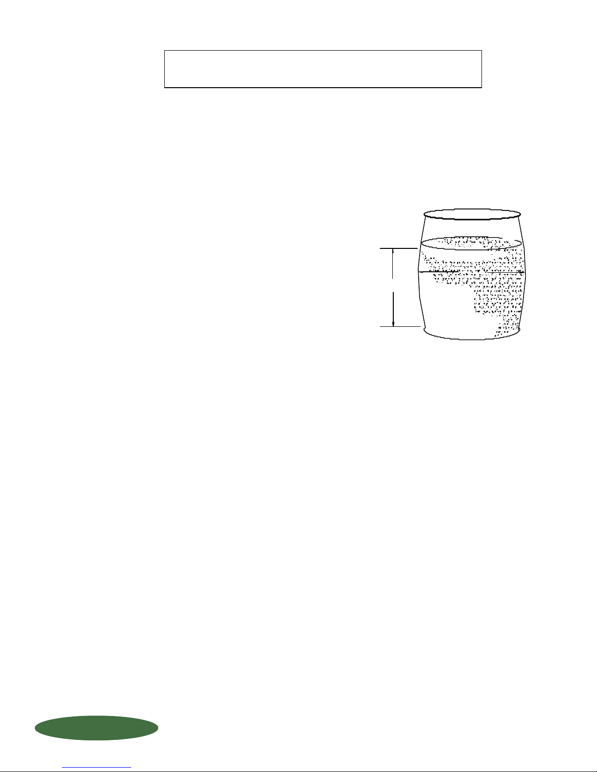
CHECKING SCALE CALIBRATION via the
"WATER TEST" on VERTICAL ROUND TANKS
TO DETERMINE TANK MEASUREMENTS:
To calculate volume, you need to make 2 basic measurements
with a tape measure: TANK "RADIUS" and WATER "HEIGHT".
STEP 1: With NO WATER in the tank,
measure the inside diameter (I.D.) of the
tank to the nearest 1/16" of an inch. Take
care when measuring so that your tape
measure is "level" and you are measuring
across the MIDDLE of the tank.
STEP 2: ZERO scale indicator, then fill the
tank with water approximately 80% full.
STEP 3: Put tape measure down through the water and
measure the water level to the nearest 1/16 of
an inch. This value represents your "HEIGHT".
TO DETERMINE VOLUME:
The volume (in gallons) of your container can be determined by this simple formula:
FORMULA: (3.1416 x Drum Radius x Drum Radius x Water Height) divided by 231 = Gallons
Example: (3.1416 X 11.281" x 11.281" x 35.187")
divided by 231 = 60.89 Gallons
3.1416 = PI (constant)
231 = Cubic inches in 1 gallon (constant)
Drum radius is half of drum inner diameter.
Example: 22-9/16" (22.562") divided by 2 = 11.281" Drum Radius
Water Height = 35-3/16 (35.1870)
Step 2:
Zero scale
indicator, then
fill 80% full
with water.
Step 3:
Measure
water height.
Step 1:
Measure tank
inside diameter.
3
1
TO DETERMINE WEIGHT:
Once the volume is determined, multiply the total gallons times the weight per gallon of water (which
is 8.34 lbs. per gallon). The weight of water is the same universally.
FORMULA:
Example: 60.89 x 8.34 lbs/gallon = 507.9 lbs. Total
IMPORTANT NOTE:
Minimum test sample: 20 gallons
All measurements should be made to + or - 1/16".
All calculations should be made to 3 decimal places (i.e. 7.225)
FORCE FLOW
FORCE FLOW
FFLLOOQQIIUUP
P
Gallons x Lbs. per gallon = Total lbs.
60.89 = Gallons as determined above
*8.34 = Weight of water (lbs. per gallon)
DO NOT GIVE CREDENCE TO "GALLON" MARKINGS ON TANK !!
THEY PROBABLY ARE NOT ACCURATE !!
S.3.201
W.3.201
1-800-893-6723 - Fax: 925-686-6713
www.forceflow.com / [email protected]
REF: T4\O&M\DRMHYD\DRMCAPCT.tcw (N05.pdf) 01/24/02
Page 37
TROUBLESHOOTING
PROBLEM
Cannot get INTO the MENU:
Cannot get OUT OF the MENU:
Cannot get OUT OF the CODE SET-UP:
AMOUNT USED and DAILY
USAGE values are incorrect.:
NET REMAINING is NOTcorrect:
FEED RATE and DAYS UNTIL
EMPTY is incorrect:
SOLUTION
- Exit CODE SET-UP function, then push "arrow" key.
- Push DELETE
- Keep pushing ENTER until you get to the display.
- When in the TANK LOAD mode, make sure you wait until the:
"CHANGE TANKS NOW" (for PORTABLE tank applications)
or "FILL TANKS NOW" (for PERMANENT tank applications)
before loading/unloading of tanks/chemicals.
- If using AUTO TARE mode, make sure you are using full tank(s).
- If you are using MANUAL TARE mode, make sure you are entering
the correct tare weight(s) for your tank(s).
- If you don't replace all tanks on a multiple tank scale, you must
use MANUAL mode.
- If all else fails, recalibrate under CODE SET-UP 9081 under field calibration.
- Read CODE SET-UP 9082 under custom formatting thoroughly and adjust accordingly.
ALARM does NOT operate:
Alarm RESET does NOT operate:
PRINTER does NOT operate:
4-20mA SIGNAL does NOT operate:
READOUT does NOT operate:
Fluctuating readings or
inacurate readings.
- Make sure you purchased this option.
- Make sure alarm for that scale is ENABLED under CODE SET-UP 4200.
- Make sure relay is wired NORMALLY OPEN under indicator wiring instructions.
- You must first correct your alarm condition before attempting to reset
(i.e. fill your tank, or load a full tank beforehand).
- Make sure printer protocol has been set properly (see #4 PRINTER COMMUNICATIONS
in Indicator Installation & Wiring)
- Printer must have at least 24 character width capability and a 2K buffer.
- Make sure you purchased this option.
- Make sure there is no more than 975 Ohms load on 4-20mA loop.
- Make sure 4-20mA signal is formatted properly under CODE SET-UP 3256.
- Check for proper power connections.
- Check fues in Indicator.
- Make sure load cell cable is not in proximity to any other power wiring.
FORCE FLOW
FORCE FLOW
FFLLOOQQIIUUP
QUESTIONS ? Help Hotline: 1-800-893-6723
P
W.3.301
1150-D Burnett Ave, Concord, CA 94520 USA
1-800-893-6723 US & Canada, Fax: 925-686-6713
www.forceflow.com / [email protected]
File: T4\O&M\AWZMSTR\WZTRBSHT.tcw (B20.pdf)
Page 38
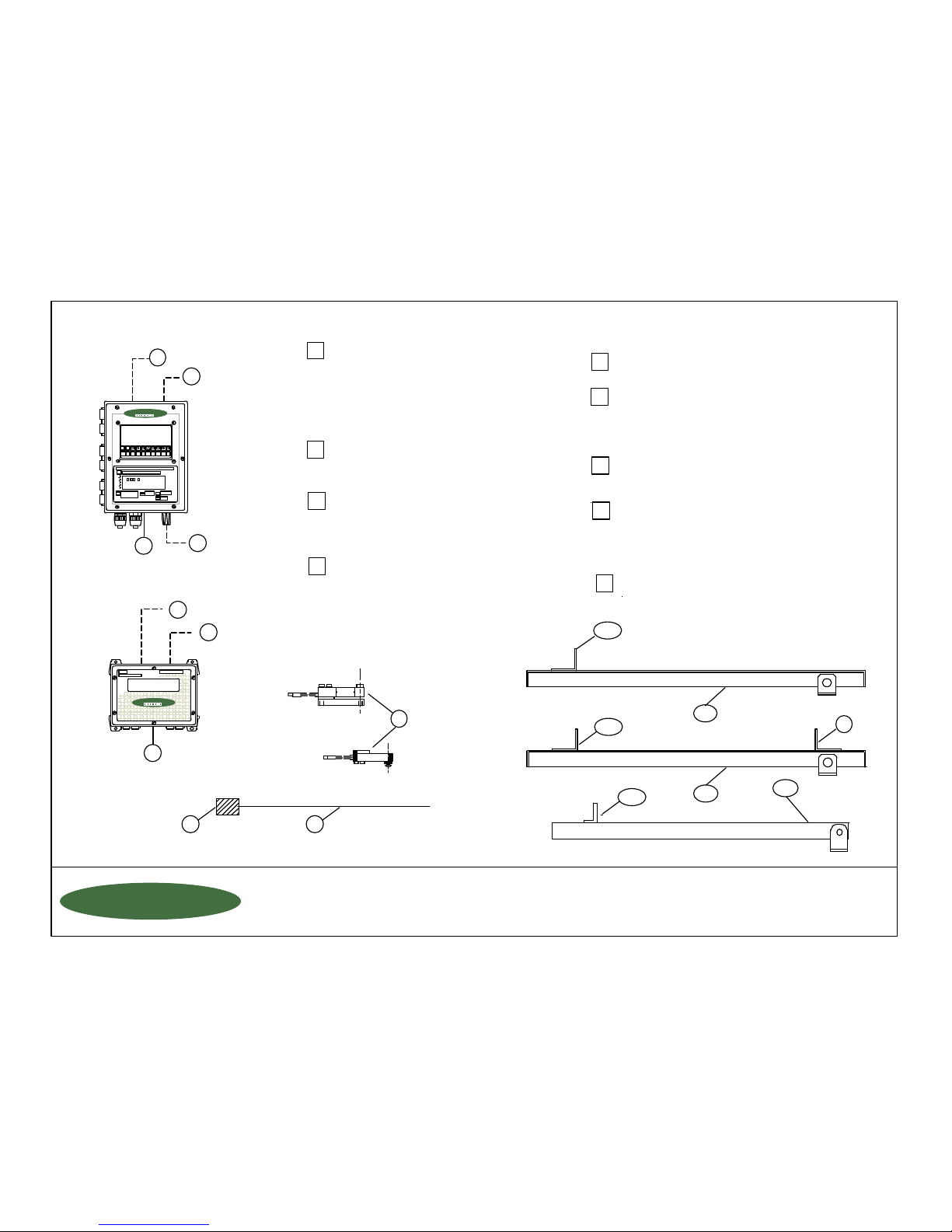
1a or b: Chem-Scale or Tote Bin Scale Platform:
30" x 30" Chem-Scale Platform
40" x 40" Chem-Scale Platform
50" x 50" Chem-Scale Platform
60" x 60" Chem-Scale Platform
72" x 72" Chem-Scale Platform
Electronic WIZARD Indicator:
Wizard 4000-1 (1-Channel)
Wizard 4000-2 (2-Channel)
Wizard 4000-3 (3-Channel)
Wizard 4000-4 (4-Channel)
Accessories for WIZARD:
W5ASP (level alarm)
WMA420 (4-20mA Output)
WRS232/WRS485 (Serial Port)
WMB4000 (Motherboard Replacement)
Electronic CHEM-SCALE or DRUMM-SCALE -- PARTS & ACCESSORIES
a) Backstop (1 for Chem Tote Bins)
b) Hold Down Clips (4 for Chem Tanks)
c) Backstop (1 for Drums)
Cable
8
2
6
5
1
3
Load Cell with Cable:
(Consult Factory on which
load cell fits your application)
Drawn by: SLP
Date: 01/01/89
Revised: 03/15/00
Scale: NONE
Drawing Number
File: T4\DRAWINGS\PARTCHDM.tcw (T07.pdf) 01/24/02
29502
ELECTRONIC CHEM-SCALE or DRUMM-SCALE
PARTS LIST for Tanks, Tote Bins or Drums
WIZARD 4000
091234567
8
SCALE 1 150 LBS
SCALE 2 300 LBS
3
6
7
5
Electronic SOLO Indicator:
Solo 1000 Single Channel
Solo 1000-2 Dual Channel
7
4
4
J10 JUNCTION BOX (to extend cable beyoond
the standard length)
J40 SUMMING BOX (to sum multiple scales or
for high accuracy applications)
1c: Drumm-Scale Frame:
27-1/2" x 27-1/2" Drumm-Scale Platform
MOTHERBOARD
(includes 4-20mA Output)
WMA420
W5ASP
9
Accessories for SOLO:
S5ASP (level alarm)
SMB1000 (Motherboard Replacement
(includes 4-20mA)
S5ASP
9
9
8
8
SERIAL PORT
8
1150-D Burnett Ave, Concord, CA 94520 USA
1-800-893-6723 US & Canada, Fax: 925-686-6713
www.forceflow.com / [email protected]
FORCE FLOW
FORCE FLOW
FFLLOOQQIIUUP
P
NET #1 150 LBS
FORCE FLOW
FORCE FLOW
FORCE FLOW
FORCE FLOW
1b
1c
2
CHEM-SCALE
DRUMM-SCALE
S.3.401
W.3.401
2a
1a
TOTE BIN SCALE
2b
2c
Page 39

R
O
F
F
C
E
W
O
L
L
H
E
0
8
1
-
f
.
w
w
w
f
@
o
f
n
i
:
E
T
O
N
S
H
P
9
8
-
0
r
c
o
r
c
o
L
O
T
-
3
o
e
f
l
o
e
f
l
E
I
N
3
2
7
6
c
m
o
.
w
c
m
o
.
w
 Loading...