

Force 12 Sigma-280 Magnum Assembly Instructions Manual
Sigma-280 Magnum
2 element 80/75 Meter Yagi Antenna
FREQUENCY COVERAGE: CW and Phone segments, each approximately 100 kHz 2:1 VSWR
Force 12, Inc.
P.O. Box 1293 Bridgeport, TX 76426
Technical Support and Order Line:1 940 683 8371 FAX 1.940 683 8378
Thank you for selecting the Force 12 Sigma-280 Magnum 2 element Yagi for 80/75 meters. Released in
the summer of 2003, the Sigma-280 Magnum is another step up in the finest 80/75 meter production Yagis.
It is the product of about 9 years of development and the Sigma design is the new era in efficient antenna
design for both horizontal and vertical antennas. Thanks to the members of Team Vertical and their years
of competitive operating that eventually led to this design. Sigma-280 Magnum is composed of a pair of
Sigma-180 Magnum dipole elements. One is the driver and the other is the reflector. Other than their
tuning, they are physically identical. The function of each element is determined by the tuning of each one
and that the coax feed line goes to the driver. This manual describes building each dipole element, the
attachment to the boom of both and how to tune the antenna. Yagis for 80/75 meters are tuned much
differently than one would expect. The old theory that the reflector is tuned 3-5% lower in frequency does
not hold. The reflector is actually tuned approximately 0.7% lower.
The Sigma-280 Magnum covers several segments of the 80/75 meter band with the 2-relay external switch
box. The antenna is composed of two elements. Each has T-bar capacitive loading about 24’ out on each
side, plus large diameter, Hi-Q coils on each side of the feed point, providing the highest efficiency of any
shortened antenna to date. The antenna is designed to present a low profile and withstand winds in excess
of 90 mph.
DW-Manual-Sigma-280 Magnum-001 FORCE 12 SIGMA-280Magnum Assembly Instructions Page 1 of 32

The Sigma design uses elements that are about 62% mechanically full size and are made electrically full
size with end loading and center loading. The Sigma-280 Magnum elements are 76’ long. The elements are
made electrically longer by adding 26’ T-bars towards each tip for end loading. This type of loading is the
most effective and coupled with the huge center loading coils, the efficiency is 96%.
Using these efficient elements results in a 2 element Yagi with forward gain at least equal to that of 3
element Yagis utilizing mid-point coil loading and a boom of >60’. Coils with a Q as high as 600 still have
loss and the mid-point placement of the coils on the element creates a current distribution that is not as
favorable as the Sigma design. Additional disadvantages of using mid-point coils are: the potential for arcover at the coil (it is typically wound on a PVC core); the covering can become ineffective over time (due
to sunlight and weather); and, the structure itself (the coil form) is vulnerable to fatigue from the everpresent wind, stress and vibration. The operating bandwidth (gain, F/B and VSWR) of the Sigma-280
Magnum is also wider than that of a coil-loaded Yagi with the same element length. This is due to the
added electrical length of the T-bars. The equivalent length of a Sigma-280 Magnum element (without the
center loading coils) is 102’.
Both elements supplied with the Sigma-280 Magnum are built the same. During assembly, one is selected
for use as the driver (the one connected to the feed line) and the other is selected as the reflector, the
parasitic element. The reflector will be tuned slightly lower in frequency than the driver and this is
accomplished by adjusting the center loading coils to the appropriate reflector frequency. The reflector is
set first, without the driver in the circuit, to the correct frequencies for phone and CW. The driver is then set
with the reflector active. Once set, the reflector is not re-adjusted, as it is pulled in frequency by the
presence of the driver. If measured by itself, the driver would resonate higher than in the 2 element Yagi,
because it is pulled down in the presence of the reflector.
The construction of the Sigma-280 Magnum elements uses all tubing. The coils are in series with each side
of the dipole and are enclosed with a large diameter styrene cover. The elements are also trussed using nonconductive line for added strength.
The power limit for this antenna is in excess of 8KW, with the limiting factor being the balun used to feed
the driver. The next limiting factor is the 30 amp relay contacts in the CW/SSB switch box. To date, these
relays have been used in many applications for more than 10 years with no failures except for a lightening
strike. The feed point is matched to 50 ohms using a hairpin (coil) match.
The Sigma-280 Magnum is a large antenna, so care should be taken during installation. The T-bars add
another dimension, so be aware of their presence. Knowing it is possible that not everyone who has
acquired the Sigma-280 Magnum is necessarily familiar with shortened elements, it is suggested that a
good book, such as the A.R.R.L. Antenna Book be utilized for further information. Of course, one can
always proceed directly and assemble the Sigma-280 Magnum!
Feed System and Antenna VSWR
The Sigma-280 Magnum feed system is straightforward. The feed point is less than 50 ohms and is stepped
up using a simple hairpin coil across the feed point. The hairpin and balun are connected to the feed point
end of the relay box and the other end of the box is connected to the feed point terminals on the driver
element on the antenna. Since this is a balanced antenna, it should be fed through either a 1:1 balun (such
as the Force 12 B-1, B-1/C), or a suitable coaxial RF choke. The reflector element has a similar relay box in
DW-Manual-Sigma-280 Magnum-001 FORCE 12 SIGMA-280Magnum Assembly Instructions Page 2 of 32

series at the center. The far side of the box (where the balun is attached on the driver) is jumpered across
with a short wire. The relays (i.e. relay #1 in each box) in both boxes are switched simultaneously (in
parallel).
The VSWR curves for the Sigma-280 Magnum allow coverage of about 100 kHz at the 2:1 points. Adding
the flexibility of the relay box, this gives the antenna 4 segments of about this bandwidth. Two (2)
segments are normally on CW and two (2) are normally on phone; however, all four (4) segments can be
set for phone. As a short note, a low or high VSWR does not necessarily mean that an antenna works or
not. A fine book addressing this is Reflections, published by the A.R.R.L.
Each element is set to the correct operating frequency by adjusting the spacing between turns on the two,
large coils located at the center of the element. The hairpin match is adjusted for the best match (usually
1:1) on the driver at the desired frequency. The input impedance at the feed point is much less than 50
ohms (about 30 ohms) and is stepped up to 50 ohms by using the hairpin match mounted across the feed
point. This hairpin is in the form of a "helical hairpin", or coil, as a typical hairpin would be physically too
large. The match to 50 ohms is adjusted by making the spacing on the coil wider or narrower. Adjustment
at the low phone position is normally sufficient for all operating segments.
Please consult FORCE 12, Inc. for any questions.
Mechanical Overview
The mechanical design of the Sigma-280 Magnum is a pair of Sigma-180 magnum dipoles attached to a
mounting plate (weldment) on each end of the boom. The mountings are bolted to the boom using several
stainless bolts. The bolts are inserted from inside the boom, through the boom and through the mount. The
non-conductive element truss is attached to the element and to the center riser post on the element mount.
The element tubing segments are both bolted and riveted. The bolted joints are on the larger tubing and the
riveted joints are on the tips and the T-bars. The riveted element is a Force 12 “first” and identifies the
product. The antenna can be fully assembled, tuned at a reasonable height (20-25’ minimum) and then
mounted in place. Antennas always shift upwards in frequency as they are raised, so checking it at as it is
raised to a reasonable height will ensure the shift is known. If one thinks about this, having an 80/75 meter
Yagi at 25’ is like having a 20 meter Yagi at 6’ above the ground. The higher the antenna is raised to check
and verify the frequencies, the more optimum the settings. Remember that the reflector frequency is going
to be set only about 35 kHz lower than the driver. It is important to do this right!
The elements are insulated from the plates and the mast. Connection to each element is through a pair of
10-24 stainless machine screws. As previously mentioned, since this is a balanced antenna and coaxial
line is unbalanced, a means to choke off antenna current from the outside of the coax feeding the
driver element should be used. Two devices are fine: one is an RF choke, made by winding several turns
of the coax in a circle close to the feed point; or, a 1:1 balun, such as the Force 12 B-1, can be used.
Most of the hardware is stainless steel. It is type 304, not 18-8, which is only rust resistant. The plated
hardware is used for the element-to-boom bracket installation, with stainless lock washers and nuts to
enable removal. Stainless U-bolts are not necessary, except in extreme environments and a preferred
method is to paint these parts. Stainless hardware is easy to gall, meaning to freeze the nut on the shaft,
rendering the bolt useless. If all stainless is required, please contact the factory. The entire antenna can be
painted to eliminate any glint in the sun, although methods have been employed to limit glint already. For
example, the tubing is all 6061-T6, with a matte finish.
DW-Manual-Sigma-280 Magnum-001 FORCE 12 SIGMA-280Magnum Assembly Instructions Page 3 of 32

On to the assembly.............................
Tools required:
A. Wrenches or ratchets.
1. 7/16"
2. 1/2"
3. 9/16"
B. A 3/8" nut driver, or small crescent wrench for the feed point 10-24 nuts.
C. Screwdriver to back-up the 10-24 feed point machine screws.
D. Cordless drill and these bits: ¼” and 1/8” or 3/16”
E. Hand riveter, also called a "POP™", or blind riveter. These are available from the company, a local
hardware store, or possibly your dealer where this antenna was purchased. This is used to secure the
element sections together. Use the smallest nozzle (tip) for the 1/8" rivets.
F. A means to control and hoist the antenna into position.
G. Some patience and common sense - be careful, as antennas can come into contact with high voltage
lines and they are lethal. Also, be careful installing, as towers and masts are also dangerous.
Thanks
The antenna is shipped in subassemblies and each assembly section is appropriately identified. The antenna
elements are divided into two (2) halves: "A" and "B". Each tubing section has either an "A" or "B" on it
and the sections taper as they go towards the tip. Assembly requires only that the identifications are
matched. All the rivet holes are pre-drilled and will align exactly when the proper sections are matched.
The elements are identical and are split at the center. The relay boxes are placed in series with each element
at the feed point. The driver is fed with 50 ohm coax through either a 1:1 balun, or other means of a current
balun (a coaxial RF choke would be quite large). The reflector is shorted across the far end of the relay box
(the same location the balun attaches on the driver).
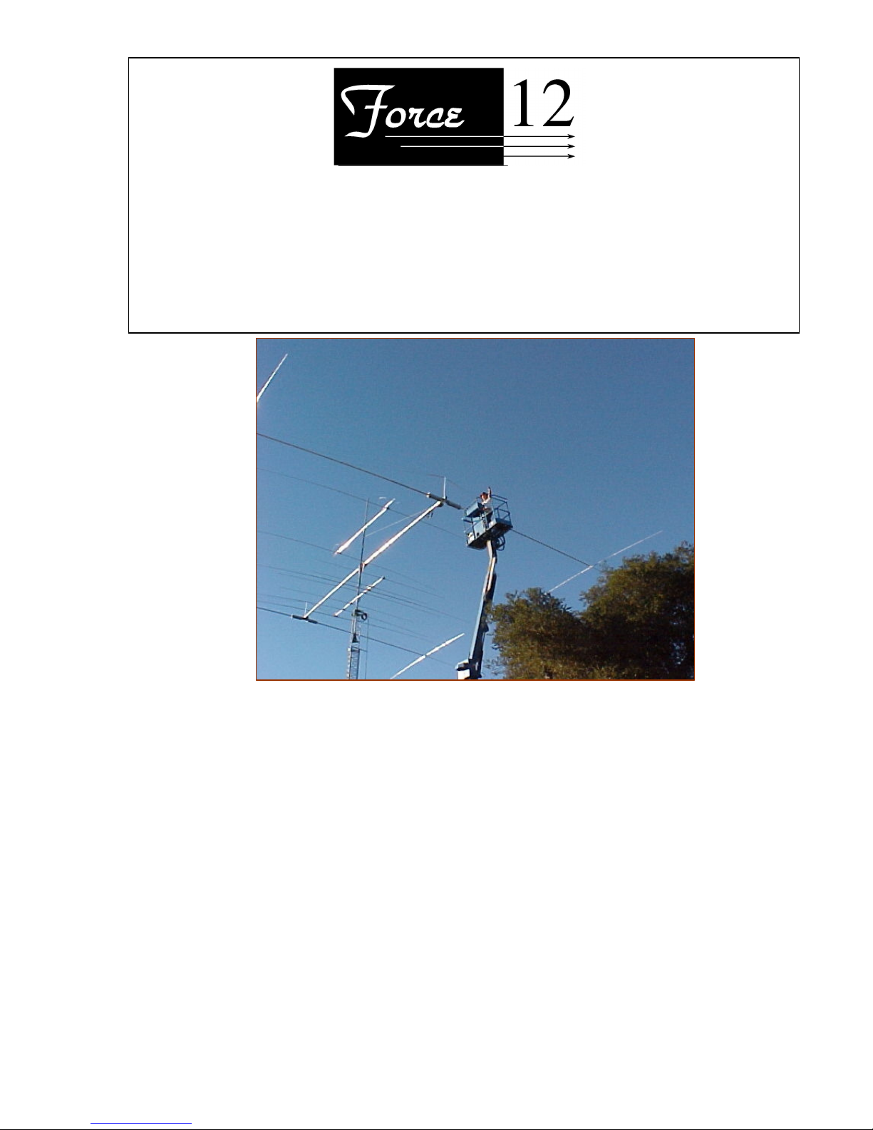
Please read all instructions carefully and also look at the pictures - they are truly worth a thousand words!
Assembly Notes:
1) Although the entire antenna has already been pre-assembled, it might be a good idea to doublecheck the measurements, especially on the elements. Please let us know if there are any discrepancies.
Thanks.
2) When using the hand riveter, please be sure the smallest nozzle is in the tool. Sometimes with a
larger nozzle, the mandrel of the rivet can get crooked within the tool, which can result in breaking the
mandrel before the rivet is "popped." The smaller nozzle also makes a smooth finish on the rivet head.
DW-Manual-Sigma-280 Magnum-001 FORCE 12 SIGMA-280Magnum Assembly Instructions Page 4 of 32

I. First is to build the individual elements. Each one is a Sigma-180 Magnum and they are
identical. Their function is determined later by which is selected for reflector and driver, then each
element’s tuning is set.
ELEMENT ASSEMBLY
_____1) NOTE: this entire antenna has already been assembled at the factory. This is how the
holes get drilled and how the subassemblies are made. This means that every piece will
align properly, provided that they are being assembled in the right position.
_____1a) It should never be necessary to drill a hole for a rivet, or bolt.
_____1b) Each element is disassembled and separately bundled, so working with one
element at a time is the best method. This will ensure that only the parts for a
particular element are available for assembly at one time.
_____1c) Please check the measurements and the element positions to double check us at
the factory. It is rare that a marking mistake is made, but it can happen.
___2) Each element is tapered and the taper runs smaller towards the tip. Each section slides into
another and to ensure a nice fit, the larger one is crimped/swaged to reduce its size slightly.
This means that one end of each section is crimped/swaged and the reduced size of one end
can be clearly seen. Only the tip is not done in this manner, since it is the end of the element.
_____2a) Please be sure that the non-crimped/swaged end goes into the crimped/swaged end of
the larger piece.
_____2b) If the rivet holes do not align, please check to be sure the section is oriented properly
and that the correct side (A or B) is on the correct side. It should not be necessary to
drill any holes.
_____2c) Thanks.
_____3) Lay out the element assembly sections.
_____a) Side A & Side B
_____b) Note how the large Sigma coils are attached on each side of the center.
_____c) Please refer to the drawings and photos.
_____d) Be sure to slide the coil covers (tubes and caps) on before completing the assembly.
_____4) Apply Noalox compound to each of the sections that will slip into another. This can be a
thin coat, spread evenly along and around the portion that is inserted into the larger tubing.
_____5) Assemble both of the tips first.
_____a) Insert the supplied 1/8" rivets into all rivet holes. It is important to insert all the
rivets before any are pulled; otherwise, there is a possibility that the other holes
might not align properly. If at any time it becomes necessary to remove a rivet, use
an 1/8" drill and use the hole at the center of the rivet as the hole guide. Even if the
hole is enlarged, the closed-end rivets will fill in the hole when they are pulled.
_____b) Pull each rivet with the hand riveter. The mandrel of the rivet (the "shaft") is inserted
into the riveter and the handles of the riveter are squeezed. Sometimes, a complete
squeeze of the riveter will not "pop" the rivet and release the mandrel. If this occurs,
release the pressure on the riveter and push it back down over the mandrel (which
will now be sticking out farther).
_____c) Slip each section into the matching larger tubing, as in the prior step and secure with
the rivets.
DW-Manual-Sigma-280 Magnum-001 FORCE 12 SIGMA-280Magnum Assembly Instructions Page 5 of 32

_____6) Assemble both of the T-bars
_____a) Using the similar technique as above, rivet each T-bar together.
_____7) Assemble the center section of the antenna.
_____a) Refer to the drawing and photos.
_____b) Be sure to add the coil cover caps and coil cover tubes before completing the
element; otherwise, the element will have to be disassembled.
_____c) Be sure to slide the PVC insulators on the center sections.
_____1. Locate the two (2) PVC center insulators and place them over the center
portions of each element half so that each insulator is to the outside of the 10/24
machine screws used at the feed point.
_____2. The U-bolts that will be holding the element to the mounting plate are
insulated from everything by the PVC insulators.
_____d) Double check that:
_____1. the two coil cover caps are on the inside of the coils (one per side).
_____2. the covers are on each element half, to the outside of the coils.
_____3. the two coil covers for the tip ends of the covers are on the element to the tip
ends of the antenna.
_____e) Using a 1/8” or 3/16” drill bit, drill four (4) holes along a straight line on each of the
cover tubes. Start the holes about 2” in from each end of the two (2) cover tubes.
These will be the drain holes. They can be drilled later, but now is a better time.
_____f) Spread the turns on the coils for about one (1) turn per inch, or about one tubing
diameter spacing between turns.
_____f) Temporarily attach the far end (T-bar end) of each coil to the element using a 2” U-
bolt and saddle.
_____8) Complete assembly of the element
_____a) Add the remainder of the larger diameter tubing using ¼ - 20 stainless bolts and ny-
loc nuts.
_____b) Add the T-bars to the brackets using the small U-bolts and hardware.
_____c) Do not over tighten the nuts, as it is not necessary to compress the tubing.
_____d) Add the non-conductive truss line to the eye-bolts on the element. These are simply
tied to the element and the center is later clamped to the mast. Set the slack for an
attachment above the element of about 2-3’
_____9) Double check that both sides "A" and "B" have been fully assembled.
_____a) Double check that the element looks like the drawings and pictures.
_____10) The element is always installed with the rivets pointing down. This will prevent any water
from sitting in the rivets, although there is no hole actually going through them.
_____11) The element mounting plate is attached next.
_____12) If not already done, remove the saddles from two (2) of the 2” U-bolt/saddle assemblies.
_____a) Do not use the saddles.
_____b) Place the 2 U-bolts over the PVC insulators and secure to the mounting plate with `
nuts and lock washers.
DW-Manual-Sigma-280 Magnum-001 FORCE 12 SIGMA-280Magnum Assembly Instructions Page 6 of 32
 Loading...