

Page 1

Traverse Hardware Guide
TR4.0.x/TN5.0.x June 2011
R
Page 2

Copyright © 2011 Force10 Networks, Inc.
All rights reserved. Force10 Networks ® reserves the right to change, modify, revise this publication without
notice.
Trademarks
Force10 Networks® and E-Series® are registered trademarks of Force10 Networks, Inc.
Traverse, T raverseEdge, T raversePacketEdge, T ransAccess, are registered trademar ks of Force10 Networks,
Inc. Force10, the Force10 logo, and TransNav are trademarks of Force10 Networks, Inc. or its affiliates in the
United States and other countries and are protected by U.S. and international copyright laws. All other brand
and product names are registered trademarks or trademarks of their respective holders.
Statement of Conditions
In the interest of improving internal design, operational function, and/or reliability, Force10 Networks, Inc.
reserves the right to make changes to products described in this document without notice. Force10 Networks,
Inc. does not assume any liability that may occur due to the use or application of the product(s) described
herein.
Page 3

CONTENTS
Chapter 1
Traverse 2000 Platform
Traverse 2000 Front View . . . . . . . . . . . . . . . . . . . . . . . . . . . . . . . . . . . . . . . 2
Traverse 2000 Rear View. . . . . . . . . . . . . . . . . . . . . . . . . . . . . . . . . . . . . . . . 3
Traverse 2000 Specifications. . . . . . . . . . . . . . . . . . . . . . . . . . . . . . . . . . . . . 4
Chapter 2
Traverse 1600 Platform
Traverse 1600 Front View . . . . . . . . . . . . . . . . . . . . . . . . . . . . . . . . . . . . . . . 2
Traverse 1600 Rear View. . . . . . . . . . . . . . . . . . . . . . . . . . . . . . . . . . . . . . . . 3
Traverse 1600 Specifications. . . . . . . . . . . . . . . . . . . . . . . . . . . . . . . . . . . . . 6
Chapter 3
Traverse 600 Platform
Traverse 600 Front View . . . . . . . . . . . . . . . . . . . . . . . . . . . . . . . . . . . . . . . . 1
Traverse 600 Rear View. . . . . . . . . . . . . . . . . . . . . . . . . . . . . . . . . . . . . . . . . 2
Traverse 600 Specifications. . . . . . . . . . . . . . . . . . . . . . . . . . . . . . . . . . . . . . 5
Chapter 4
Fan Assemblies
Traverse Fan Assemblies. . . . . . . . . . . . . . . . . . . . . . . . . . . . . . . . . . . . . . . . 1
Traverse 2000 and Traverse 1600 Front Inlet Fan Assemblies. . . . . . . . . . . 2
Traverse 600 Fan Assembly . . . . . . . . . . . . . . . . . . . . . . . . . . . . . . . . . . . . . 3
Fan Assembly Specifications . . . . . . . . . . . . . . . . . . . . . . . . . . . . . . . . . . . . . 4
Chapter 5
Power Distribution and Alarm Panels
PDAP-4S . . . . . . . . . . . . . . . . . . . . . . . . . . . . . . . . . . . . . . . . . . . . . . . . . . . . 2
PDAP-15A . . . . . . . . . . . . . . . . . . . . . . . . . . . . . . . . . . . . . . . . . . . . . . . . . . . 3
PDAP Specifications . . . . . . . . . . . . . . . . . . . . . . . . . . . . . . . . . . . . . . . . . . . 3
Chapter 6
General Control Module (GCM) Cards
GCM Card Description. . . . . . . . . . . . . . . . . . . . . . . . . . . . . . . . . . . . . . . . . . 2
GCM Card Types . . . . . . . . . . . . . . . . . . . . . . . . . . . . . . . . . . . . . . . . . . . . . . 5
Card Specifications . . . . . . . . . . . . . . . . . . . . . . . . . . . . . . . . . . . . . . . . . . . . 7
Chapter 7
Next-Generation Ethernet Cards
NGE / NGE Plus Card Description. . . . . . . . . . . . . . . . . . . . . . . . . . . . . . . . . 1
NGE/NGE Plus Card Types. . . . . . . . . . . . . . . . . . . . . . . . . . . . . . . . . . . . . . 3
NGE / NGE Plus Card Specifications. . . . . . . . . . . . . . . . . . . . . . . . . . . . . . . 4
NGE Gigabit Ethernet Ports. . . . . . . . . . . . . . . . . . . . . . . . . . . . . . . . . . . . . . 7
GbE CWDM Wavelengths . . . . . . . . . . . . . . . . . . . . . . . . . . . . . . . . . . . . . . . 8
NGE Fast Ethernet Ports . . . . . . . . . . . . . . . . . . . . . . . . . . . . . . . . . . . . . . . . 8
Traverse Hardware Guide, Release TR4.0.x 1
Page 4

Chapter 8
Gigabit Ethernet-only Cards (Dual-slot)
1-Port 10GbE Card. . . . . . . . . . . . . . . . . . . . . . . . . . . . . . . . . . . . . . . . . . . . . 2
10-Port GbE Card. . . . . . . . . . . . . . . . . . . . . . . . . . . . . . . . . . . . . . . . . . . . . . 6
GbE-10 Gigabit Ethernet Ports. . . . . . . . . . . . . . . . . . . . . . . . . . . . . . . . . . . . 9
Comparing Gigabit Ethernet Payload Capacity . . . . . . . . . . . . . . . . . . . . . . . 11
Chapter 9
Ethernet Over PDH Cards
EoPDH Card. . . . . . . . . . . . . . . . . . . . . . . . . . . . . . . . . . . . . . . . . . . . . . . . . . 2
Gigabit Ethernet Ports on EoPDH Cards . . . . . . . . . . . . . . . . . . . . . . . . . . . . 5
EoPDH Fast Ethernet Ports . . . . . . . . . . . . . . . . . . . . . . . . . . . . . . . . . . . . . . 6
Chapter 10
SONET/SDH Cards
OC-3/STM-1 Cards. . . . . . . . . . . . . . . . . . . . . . . . . . . . . . . . . . . . . . . . . . . . . 2
OC-12/STM-4 Cards. . . . . . . . . . . . . . . . . . . . . . . . . . . . . . . . . . . . . . . . . . . . 4
OC-48/STM-16 Cards. . . . . . . . . . . . . . . . . . . . . . . . . . . . . . . . . . . . . . . . . . . 6
8-Port OC-48 Card . . . . . . . . . . . . . . . . . . . . . . . . . . . . . . . . . . . . . . . . . . . . . 9
OC-48 LR / STM-16 LH CWDM Wavelengths . . . . . . . . . . . . . . . . . . . . . . . . 12
OC-48 ELR / STM-16 ELH ITU DWDM Wavelengths . . . . . . . . . . . . . . . . . . 13
OC-192/STM-64 Cards. . . . . . . . . . . . . . . . . . . . . . . . . . . . . . . . . . . . . . . . . . 14
OC-192 LR / STM-64 LH ITU DWDM Wavelengths. . . . . . . . . . . . . . . . . . . . 17
OC-192 ELR / STM-64 LH ITU DWDM Wavelengths. . . . . . . . . . . . . . . . . . . 18
Chapter 11
Electrical Cards
28-Port DS1 Card. . . . . . . . . . . . . . . . . . . . . . . . . . . . . . . . . . . . . . . . . . . . . . 2
12-Port DS3/E3/EC-1 Clear Channel Card. . . . . . . . . . . . . . . . . . . . . . . . . . . 4
24-Port DS3/E3/EC-1 Clear Channel Card. . . . . . . . . . . . . . . . . . . . . . . . . . . 6
12-Port DS3/EC-1 Transmux Card. . . . . . . . . . . . . . . . . . . . . . . . . . . . . . . . . 8
24-Port DS3/EC-1 Universal Transmux Card (UTMX-24) . . . . . . . . . . . . . . . 10
48-Port DS3/EC-1 Universal Transmux Card (UTMX-48) . . . . . . . . . . . . . . . 12
21-Port E1 Card . . . . . . . . . . . . . . . . . . . . . . . . . . . . . . . . . . . . . . . . . . . . . . . 14
Chapter 12
VT/VC Switching Cards
VT/VC Switching Features . . . . . . . . . . . . . . . . . . . . . . . . . . . . . . . . . . . . . . . 1
VT/TU 5G Switch Card. . . . . . . . . . . . . . . . . . . . . . . . . . . . . . . . . . . . . . . . . . 2
VT-HD 40G Switch Card. . . . . . . . . . . . . . . . . . . . . . . . . . . . . . . . . . . . . . . . . 3
VTX/VCX Integrated Cards. . . . . . . . . . . . . . . . . . . . . . . . . . . . . . . . . . . . . . . 4
2 Traverse Hardware Guide, Release TR4.0.x
Page 5

Chapter 1 Traverse 2000 Platform
Introduction
The Traverse 2000 platform is a 20-slot, 23-inch, rack-mountable shelf optimized for
stacked ring, metro/IOF hub switching and transport applications. The Traverse 2000 is
also scalable to 95 Gbps of STS/STM switching capacity, with the industry’s highest
DS1/E1 to OC-192/STM-64, 10/100, and Gigabit Ethernet (GbE) service densities.
This platform also offers a high-capacity wideband digital cross-connect matrix scales
from 96 to 384 protected STS/STM equivalents (2688 to 10,752 VT1.5s).
Note: If using a Traverse 2000 in a SONET-only DCS-768 matrix shelf configuration,
the platform supports 768 protected STS equivalents (21,504 VT1.5s).
This section has information on the following topics:
• Traverse 2000 Front View
• Traverse 2000 Rear View
• Traverse 2000 Specifications
Traverse Hardware Guide, Release TR4.0.x 1
Page 6
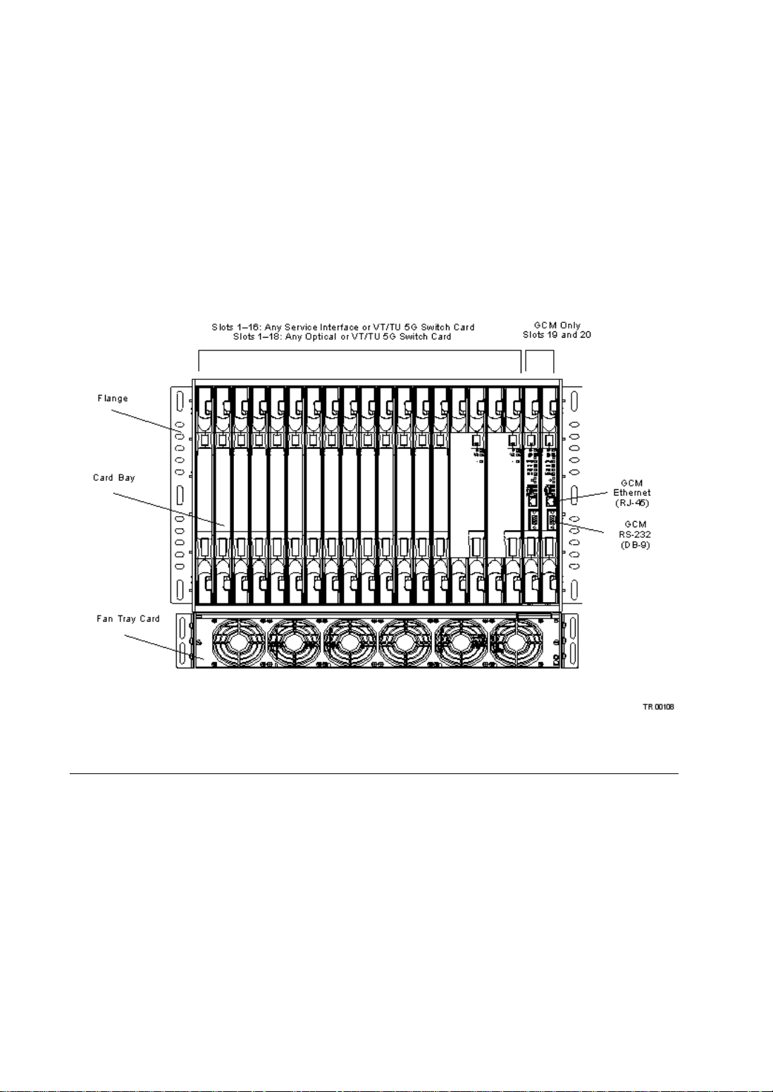
Traverse 2000 Front View
For most node configurations, eighteen slots accommodate service interface modules
and VT/TU 5G Switch cards, and two slots are dedicated to General Control Module
(GCM) cards. The Traverse 2000 shelf is configured by populating the system with
GCMs (control cards), service interface modules (SIMs or cards), and VT/TU 5G
Switch cards. Card guide rails are built into the shelf to allow for easy insertion of the
cards into connectors mounted on the backplane.
Note: For nodes configured as a DCS-768 matrix shelf, the system supports VT-HD
40G Switch cards only.
Figure 2 Front View of Traverse 2000
2 Traverse Hardware Guide, Release TR4.0.x
Page 7
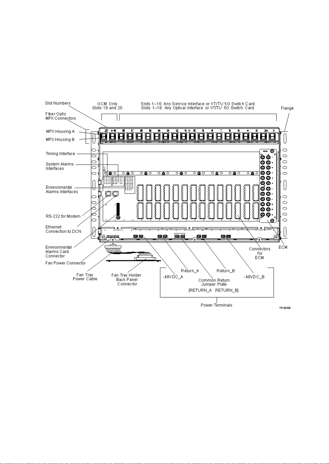
Traverse 2000 Rear View
The Traverse system’s fully-meshed passive backplane provides full interconnection
for cards and external interfaces such as power, timing, alarm, management, and the fan
tray card. All power and interface connections are terminated from the rear of the
Traverse shelf, except for the serial interface and the Ethernet port (for local craft
access), which are on the front faceplate of the control card.
Figure 3 Rear View of Traverse 2000
Slot Numbers. There are 20 slots in each T raverse 2000 shelf. For all nodes except the
DCS-768, the slot usage is:
• Slots 19 and 20 are reserved for GCM cards (control cards)
• Slots 1 through 16 are for any service interface or VT/TU 5G Switch card
• Slots 1 through 18 are for any optical interface or VT/TU 5G Switch card
For nodes commissioned as DCS-768, the slot usage is:
• Slots 19 and 20 are reserved for UGCM-XM cards (control cards)
• Slots 1 through 6 are reserved for UTMX cards
• Slots 7 through 14 are reserved for dual-slot 8-port OC-48 cards
• Slots 16 through 18 are for dual slot VT-HD 40G Switch cards
Traverse Hardware Guide, Release TR4.0.x 3
Page 8

For information on ECMs, see the Traverse Cabling and Cabling Specifications Guide,
Chapter 2—“ECM Interface Specifications.”
Traverse 2000 Specifications
This table lists the specifications for the Traverse 2000 platform.
T able 1 Traverse 2000 Specifications
Parameter Specification
Number of shelves per 7-foot rack 4
System configuration 20-slot shelf:
• 2 slots for redundant control cards
• 18 slots for universal service interface module (SIM) cards
Maximum switching capacity 95 Gbps
Power consumption 600 to 850 W atts typical (max. 1712 Watts including
front-inlet fan tray)
Redundant DC inputs
Operating range: -40 VDC to -60 VDC
Dimensions (height includes fan tray,
depth includes cable covers)
Weight Empty: 16 lbs
Operating temperature -5° C to +55° C
Humidity 90% maximum. Non-condensing
18.33 H x 21.1 W x 13.75 D (inches)
46.56 H x 53.6 W x 34.93 D (centimeters)
Fully loaded including fan: 63 lbs
Empty: 7.2 kg
Fully loaded including fan: 28.58 kg
1
4 Traverse Hardware Guide, Release TR4.0.x
Page 9

Table 1 Traverse 2000 Specifications (continued)
Parameter Specification
Supported service interface module
cards
Supported common cards • Control card
• 28-port DS1
• 12-port DS3/E3/EC-1 Clear Channel
• 24-port DS3/E3/EC-1 Clear Channel
• 12-port DS3/EC-1 Transmux
• 24-port Universal Transmux
• 48-port Universal Transmux
• 21-port E1
• 4- and 8-port OC-3/STM-1
• 16-port OC-3
• 4-port OC-12/STM-4
• 1- and 2-port OC-48/STM-16
• 8-port OC-48
2
• 1-port OC-192/STM-64
• 4-port GbE (LX or SX) plus 16-port 10/100BaseTX
[CEP/[EoPDH]]
• 4-port GbE CWDM (40 km) plus 16-port 10/100BaseTX
• 2-port GbE TX plus 2-port GbE (LX or SX) plus 16-port
10/100BaseTX [CEP/[EoPDH]]
• 2-port GbE LX CWDM plus 2-port GbE SX plus 16-port
10/100BaseTX
• Control card with VTX
• Control card with integrated optics
• Control card with integrated optics plus VTX
•VT/TU 5G Switch
• VT-HD 40G Switch
1
Carefully plan your power supply capacity. See the Planning and Engineering Guide,
Chapter 1—“Traverse Equipment Specifications,” Power Consumption.
2
The following cards can only be used in a DCS-768 matrix shelf: 8-port OC-48, VT -HD 40G switch card,
and UGCM-XM.
Traverse Hardware Guide, Release TR4.0.x 5
Page 10

6 Traverse Hardware Guide, Release TR4.0.x
Page 11

Chapter 2 Traverse 1600 Platform
Introduction
The Traverse 1600 is a 16-slot, 19-inch rack-mountable shelf optimized for access and
metro/IOF ring switching, as well as transport applications. The Traverse 1600 is also
scalable to 75 Gbps STS/STM switching capacity with high-density DS1/E1 to
OC-192/STM-64, 10/100, and Gigabit Ethernet (GbE) service flexibility.
This section has information on the following topics:
• Traverse 1600 Front View
• Traverse 1600 Rear View
• Traverse 1600 Specifications
Traverse Hardware Guide, Release TR4.0.x 1
Page 12

Traverse 1600 Front View
Fourteen slots accommodate service interface and VT/TU 5G Switch cards, and two
slots are dedicated to general control module cards (control cards). The Traverse 1600
shelf is configured by populating the system with control cards, SIMs, and VT/TU 5G
Switch cards. Card guide rails are built into the shelf to allow for easy insertion of the
cards into connectors mounted on the backplane.
Figure 3 Front View of Traverse 1600
2 Traverse Hardware Guide, Release TR4.0.x
Page 13
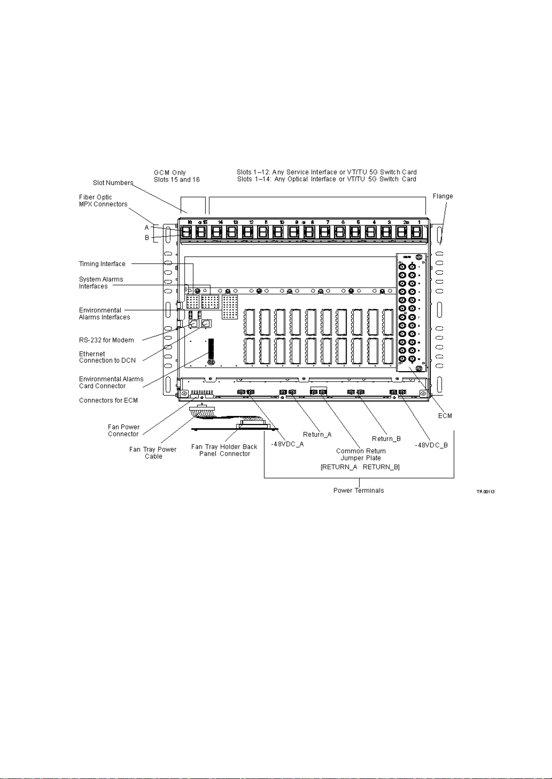
Traverse 1600 Rear View
The Traverse system’s fully-meshed passive backplane provides full interconnection
for cards and external interfaces such as power, timing, alarm, management, and the fan
tray card. All power and interface connections are terminated from the rear of the
Traverse shelf, except for the serial interface and the Ethernet port (for local craft
access), which are on the front faceplate of the control card.
Figure 4 Rear View of Traverse 1600
Slot Numbers. There are 16 slots in each Traverse 1600 shelf:
• Slots 15 and 16 are reserved for general control module cards (control cards)
• Slots 1 through 12 slots are for any service interface or VT/TU 5G Switch card
• Slots 1 through 14 slots are for any optical service interface or VT/TU 5G Switch
card
MPX Connectors
The Traverse shelf uses MPX optical fiber connectors to provide high-density and
easy-operation fiber connection for SONET/SDH and Gigabit Ethernet (SX and LX)
optical interface cards. The MPX connector design specifically supports high fiber
density applications in accordance with Bellcore GR-1435-CORE generic requirements
for multi-fiber connectors. Each slot has receptacles for up to two MPX ribbon fiber
connectors. Each connector supports from 1 to 12 fiber pairs, for a maximum fiber
count of 48 per slot.
Traverse Hardware Guide, Release TR4.0.x 3
Page 14

Timing Interface
The backplane provides primary and secondary T1/E1 and CC2M (Composite
Clock—64 kHz and 2 MHz) input and output timing interfaces, and primary and
secondary BITS input timing interfaces. These timing interfaces are routed to both
control cards, which distribute system timing references to all cards.
System and Environmental Alarms Interface
Support is provided for the full set of system alarm outputs, sixteen environmental
alarm inputs, a fail-safe alarm, and a remote alarm cut-off. The environmental
telemetry inputs and outputs are supported by the optional Environmental Alarm Card
located on the main backplane, which provides additional system-management
functions to accommodate customer-defined alarm input/output requirements. The card
is field replaceable and can be replaced without disconnecting the alarm wiring.
Modem Interface
The RS-232C modem interface uses a vertical 8-pin RJ-45 connector that is configured
as a data terminal equipment (DTE) port for connection to an external modem,
supporting dial-up remote access to the active control card. Dial-up access can also be
achieved by installing a terminal server on the DCN and communicating via Telnet to
any other Traverse node on the network. A local VT -100 terminal (or a PC with VT-100
terminal emulation software) can also be connected to the RS-232C connector
(Backplane interface).
Ethernet Connection to Data Communications Network
The Traverse system has a 10/100BaseT Ethernet interface that can be used to connect
a Traverse node to the TransNav system (or to another EMS) and to other remote
management devices. The RJ-45 signal connections are bridged to both the primary and
secondary control cards. This enables the TransNav management system to always talk
to the active control card, even after a protection switching.
In-band Management
A network of Traverse nodes can be managed over the service provider’s data
communications network (DCN) as long as at least one Traverse node is directly
connected to that network through the Traverse DCN Ethernet interface. Traverse
nodes that have no direct connection to a DCN can communicate with the EMS
indirectly, through any Traverse node that is connected to the DCN.
Out-of-band Management
A Traverse node that is not directly connected to a DCN is able to learn a route to
Traverse nodes on the DCN without any explicit local provisioning of routing
information, as long as it is connected via the Force10 Control Plane to one or more
gateway Traverse nodes. Service providers must use static IP routes to enable devices
on the DCN to reach both gateway and non-gateway Traverse nodes.
4 Traverse Hardware Guide, Release TR4.0.x
Page 15

Quality of Service
Traverse IP quality of service (IP QoS) provides filters and priority queueing with
statistics for all the traffic going over the Traverse DCC network. Priority is given to
traffic originating from the Traverse network and the TransNav server. An access
control list (ACL) manages IP hosts and networks for IP forwarding action to allow or
block traffic. Classifiers and queues prioritize and manage the IP forwarding based on
high priority or best effort.
Proxy ARP Management
The Traverse supports proxy address resolution protocol (ARP) on the Ethernet DCN
interface. Proxy ARP is the technique in which one host, usually a router, answers ARP
requests intended for another machine. By faking its identity, the router accepts
responsibility for routing packets to the real destination. Using proxy ARP in a network
helps machines on one subnet reach remote subnets without configuring routing or a
default gateway.
Power Terminals
The Traverse receives redundant -48 VDC feeds from the PDAP (PDAP-4S,
PDAP-15A, or legacy PDAP-4S) or third-party power distribution unit and distributes
these to each slot. Each slot has access to both A and B -48 VDC power feeds.
Electrical Connector Cards for Electrical Interfaces
The electrical connector cards (ECMs) enable copper and coax network interface
cabling using industry-standard cables and connectors.
For more information on ECMs, see the Traverse Cabling and Cabling Specifications
Guide, Chapter 2—“ECM Interface Specifications.”
Traverse Hardware Guide, Release TR4.0.x 5
Page 16

Traverse 1600 Specifications
This table lists the specifications for the Traverse 1600 platform.
T able 5 Traverse 1600 Specifications
Parameter Specification
Number of shelves per 7-foot rack 4
System configuration 16-slot shelf:
• 2 slots for redundant control cards
• 14 slots for universal service interface module cards
Maximum switching capacity 75 Gbps
Power consumption 400 to 650 W atts, typical (max. 1367 Watts, including front
inlet fan tray)
Redundant DC inputs
Operating range: -40 VDC to -60 VDC
Dimensions (height includes fan tray,
depth includes cable covers)
Weight Empty: 15 lbs
Operating temperature -5° C to +55° C
Humidity 90% maximum. Non-condensing
Supported service interface module
cards
Supported common cards • Control card
18.33 H x 17.25 W x 13.75 D in inches
46.56 H x 43.82 W x 34.93 D in centimeters
Fully loaded including fan: 52 lbs
Empty: 6.8 kg
Fully loaded including fan: 23.59 kg
• 28-port DS1
• 12-port DS3/E3/EC-1 Clear Channel
• 24-port DS3/E3/EC-1 Clear Channel
• 12-port DS3/EC-1 Transmux
• 24-port Universal Transmux
• 48-port Universal Transmux
• 21-port E1
• 4- and 8-port OC-3/STM-1
• 4-port OC-12/STM-4
• 16-port OC-3
• 1- and 2-port OC-48/STM-16
• 1-port OC-192/STM-64
• 4-port GbE (LX or SX) plus 16-port 10/100BaseTX
[CEP/[EoPDH]]
• 4-port GbE CWDM (40 km) plus 16-port 10/100BaseTX
• 2-port GbE TX plus 2-port GbE (LX or SX) plus 16-port
10/100BaseTX [CEP/[EoPDH]]
• 2-port GbE LX CWDM plus 2-port GbE SX plus 16-port
10/100BaseTX
• Control card with VTX
• Control card with integrated optics
• Control card with integrated optics plus VTX
• VT/TU 5G Switch
6 Traverse Hardware Guide, Release TR4.0.x
Page 17
Chapter 3 Traverse 600 Platform
Introduction
Traverse 600 Front View
The Traverse 600 system is physically smaller than the Traverse 1600 and Traverse
2000 systems, and is most efficiently used by service providers and carriers that do not
require the capacity of a full 16-slot or 20-slot shelf.
• Traverse 600 Front View
• Traverse 600 Rear View
• Traverse 600 Specifications
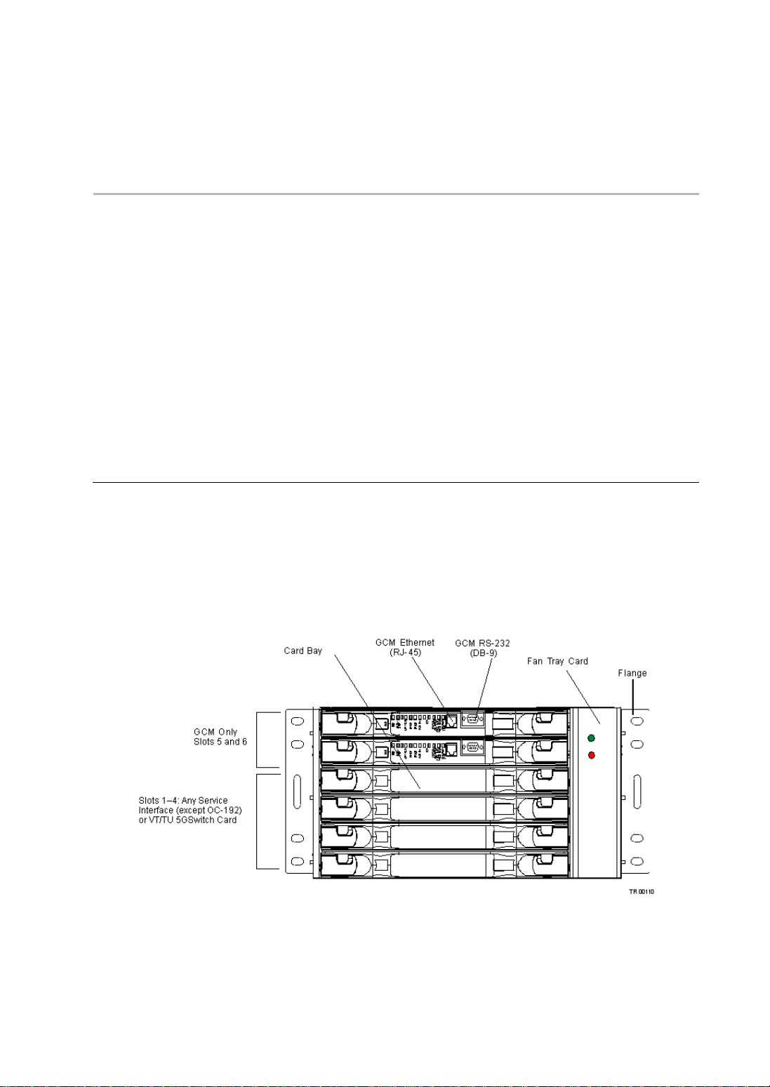
The Traverse 600 system has a total of six plug-in slots and can be mounted in standard
19-inch (483 mm) and 23-inch (584 mm) wide racks. Four slots accommodate service
or VT/TU 5G Switch cards, and two slots are for general control module cards (control
cards) or control cards with optional integrated OC-12/STM-4 or OC-48/STM-16
transport.
The unit also has a vertical slot for a field-replaceable fan module. The fan module
consists of a fan controller, six fans, and an air filter.
Figure 4 Front View of Traverse 600
Traverse Hardware Guide, Release TR4.0.x 1
Page 18
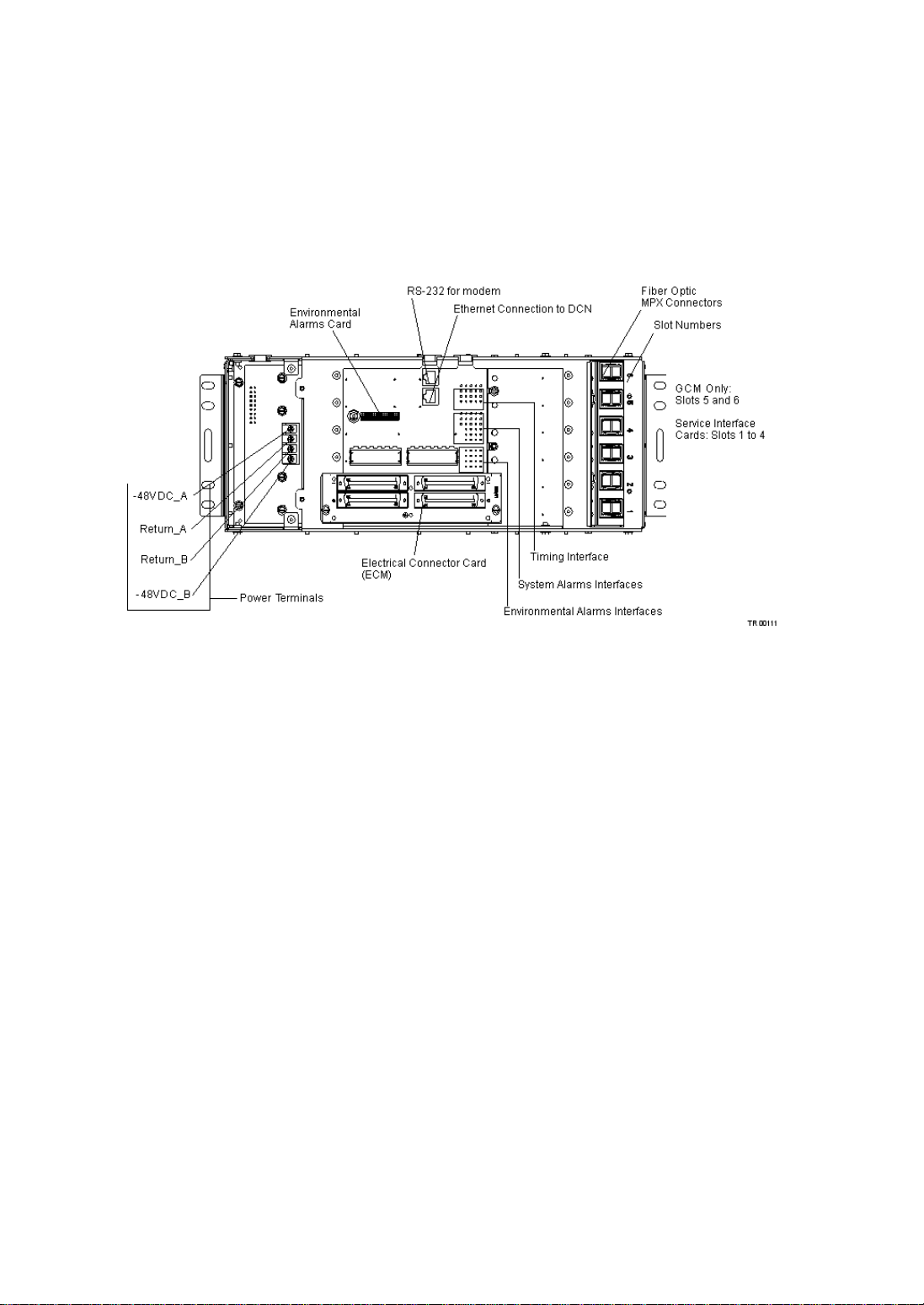
Traverse 600 Rear View
The Traverse system’s fully-meshed passive backplane provides full interconnection
for cards and external interfaces such as power , timing, alarm, management, and the fan
tray card. All power and interface connections are terminated from the rear of the
Traverse shelf, except for the serial interface and the Ethernet port (for local craft
access), which are on the front faceplate of the control card.
Figure 5 Rear View of Traverse 600
Slot Numbers. There are 6 slots in each Traverse 600 shelf:
• 2 slots are reserved for general control module cards
• 4 slots are for any service interface and VT/TU 5G Switch cards
MPX Connectors
The Traverse shelf uses MPX optical fiber connectors to provide high-density and
easy-operation fiber connection for SONET/SDH and Gigabit Ethernet (SX and LX)
optical interface cards. The MPX connector design specifically supports high fiber
density applications in accordance with Bellcore GR-1435-CORE generic requirements
for multi-fiber connectors. Each slot has receptacles for up to two MPX ribbon fiber
connectors. Each connector supports from 1 to 12 fiber pairs, for a maximum fiber
count of 48 per slot.
Timing Interface
The backplane provides primary and secondary T1/E1 and CC2M (Composite
Clock—64 kHz and 2 MHz) input and output timing interfaces, and primary and
secondary BITS input timing interfaces. These timing interfaces are routed to both
control cards, which distribute system timing references to all cards.
System and Environmental Alarms Interface
Support is provided for the full set of system alarm outputs, sixteen environmental
alarm inputs, a fail-safe alarm, and a remote alarm cut-off. The environmental
2 Traverse Hardware Guide, Release TR4.0.x
Page 19

telemetry inputs and outputs are supported by the optional Environmental Alarm Card
located on the main backplane, which provides additional system-management
functions to accommodate customer-defined alarm input/output requirements. The card
is field replaceable and can be replaced without disconnecting the alarm wiring.
Modem Interface
The RS-232C modem interface uses a vertical 8-pin RJ-45 connector that is configured
as a data terminal equipment (DTE) port for connection to an external modem,
supporting dial-up remote access to the active control card. Dial-up access can also be
achieved by installing a terminal server on the DCN and communicating via Telnet to
any other Traverse node on the network. A local VT -100 terminal (or a PC with VT-100
terminal emulation software) can also be connected to the RS-232C connector
(Backplane interface).
Ethernet Connection to Data Communications Network
The Traverse system has a 10/100BaseT Ethernet interface that can be used to connect
a Traverse node to the TransNav system (or to another EMS) and to other remote
management devices. The RJ-45 signal connections are bridged to both the primary and
secondary control cards. This enables the TransNav management system to always talk
to the active control card, even after a protection switching.
In-band Management
A network of Traverse nodes can be managed over the service provider’s data
communications network (DCN) as long as at least one Traverse node is directly
connected to that network through the Traverse DCN Ethernet interface. Traverse
nodes that have no direct connection to a DCN can communicate with the EMS
indirectly, through any Traverse node that is connected to the DCN.
Out-of-band Management
A Traverse node that is not directly connected to a DCN is able to learn a route to
Traverse nodes on the DCN without any explicit local provisioning of routing
information, as long as it is connected via the Force10 Control Plane to one or more
gateway Traverse nodes. Service providers must use static IP routes to enable devices
on the DCN to reach both gateway and non-gateway Traverse nodes.
Quality of Service
Traverse IP quality of service (IP QoS) provides filters and priority queueing with
statistics for all the traffic going over the Traverse DCC network. Priority is given to
traffic originating from the Traverse network and the TransNav server. An access
control list (ACL) manages IP hosts and networks for IP forwarding action to allow or
block traffic. Classifiers and queues prioritize and manage the IP forwarding based on
high priority or best effort.
Proxy ARP Management
The Traverse supports proxy address resolution protocol (ARP) on the Ethernet DCN
interface. Proxy ARP is the technique in which one host, usually a router, answers ARP
requests intended for another machine. By faking its identity, the router accepts
responsibility for routing packets to the real destination. Using proxy ARP in a network
Traverse Hardware Guide, Release TR4.0.x 3
Page 20

helps machines on one subnet reach remote subnets without configuring routing or a
default gateway.
Power Terminals
The Traverse receives redundant -48 VDC feeds from the PDAP (PDAP-4S,
PDAP-15A, or legacy PDAP-4S) or third-party power distribution unit and distributes
these to each slot. Each slot has access to both A and B -48 VDC power feeds.
Electrical Connector Cards for Electrical Interfaces
The electrical connector cards (ECMs) enable copper and coax network interface
cabling using industry-standard cables and connectors.
4 Traverse Hardware Guide, Release TR4.0.x
Page 21
Traverse 600 Specifications
This table lists the specifications for the Traverse 600 platform.
Table 6 Traverse 600 Specifications
Parameter Specification
System configuration 6-slot shelf:
2 slots for redundant control cards
4 slots for universal service interface module cards
Maximum switching capacity 15 Gbps
Power consumption 150 to 250 Watts, typical (max. 492 Watts)
Redundant DC inputs
Operating Range: -40 VDC to -60 VDC
Dimensions 6.5 H x 17.25 W x 13.75 D (inches)
16.51 H x 43.82 W x 34.93 D (centimeters)
Weight Fully loaded including fan: < 25 lbs
Fully loaded including fan: < 11.34 kg
Operating temperature -5° C to +55° C
Humidity 90% maximum. Non-condensing
Supported service interface module
cards
Supported common cards • Control card
• 28-port DS1
• 12-port and DS3/E3/EC-1 Clear Channel
• 24-port DS3/E3/EC-1 Clear Channel
• 12-port DS3/EC-1 Transmux
• 24-port Universal Transmux
• 48-port Universal Transmux
• 21-port E1
• 4- and 8-port OC-3/STM-1
• 16-port OC-3
• 4-port OC-12/STM-4
• 1- and 2-port OC-48/STM-16
• 4-port GbE (LX or SX) plus 16-port 10/100BaseTX
[CEP/[EoPDH]]
• 4-port GbE CWDM (40 km) plus 16-port 10/100BaseTX
• 2-port GbE TX plus 2-port GbE (LX or SX) plus 16-port
10/100BaseTX [CEP/[EoPDH]]
• 2-port GbE LX CWDM plus 2-port GbE SX plus 16-port
10/100BaseTX
• Control card with VTX
• Control card with integrated optics
• Control card with integrated optics plus VTX
• VT/TU 5G Switch
Traverse Hardware Guide, Release TR4.0.x 5
Page 22

6 Traverse Hardware Guide, Release TR4.0.x
Page 23

Chapter 4 Fan Assemblies
Introduction
Traverse Fan Assemblies
The Traverse fan assemblies cool the control card and service cards in the shelf. The
fan assembly draws in cooling air and pushes the air through the perforated shelf.
This chapter includes the following topics:
• Traverse Fan Assemblies
• Fan Assembly Specifications
Each Traverse shelf requires one fan assembly that includes the following basic
features:
• Multiple fans in each fan assembly
• Circuitry for event and alarm reporting to the general control module cards (control
card)
• Generates cool air flow to cards even if one of the multiple fans fail to operate
• Receives redundant power from the Traverse system
The system increases fan speed when temperature levels are detected that exceed the
factory-set threshold. If an individual control card or service card exceeds 59 ºC, the
control card raises an alarm (TEMPWARN) in the user interface (GUI) and increases
the speed of the fans.
Also, if any one of the multiple fans in a fan assembly fails to operate, the following
actions occur:
• The LED on the front of the fan assembly turns red
• The System increases the speed of the other fans
• The control card raises an alarm in the GUI
Traverse fan assembly differences are as follows:
• Traverse 2000 and Traverse 1600 Front Inlet Fan Assemblies
• Traverse 600 Fan Assembly
Traverse Hardware Guide, Release TR4.0.x 1
Page 24
Traverse 2000
Power
(green)
Fan Failure
(red)
FanFlange
and Traverse
1600 Front
Inlet Fan
Assemblies
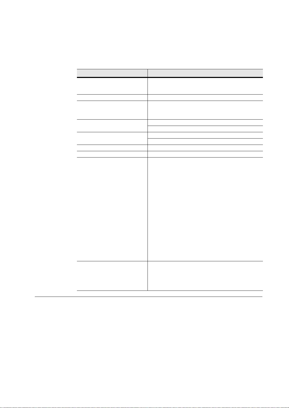
One fan assembly installs in the rack directly below each Traverse shelf.
The Traverse 1600 and Traverse 2000 front inlet fan assembly (fan tray with integrated
air ramp and fan card) cools the GCM and service cards in the shelf. The Traverse 1600
fan assembly has five fans. The Traverse 2000 fan assembly has six fans. The fans draw
in cooling air from the front and push the air upward through the perforated shelf. The
air ramp above the shelf directs the heated air out through the rear of the shelf. Each
front inlet fan assembly can force up to 200 cubic feet per minute of cooling air.
Use one fan assembly per Traverse shelf. The Traverse 1600 system fan assembly is
mountable in either 19-inch (483 mm) or 23-inch (584 mm) wide racks. The Traverse
2000 system fan assembly fits into 23-inch (584 mm) racks.
The front inlet fan assembly not only receives redundant power from the Traverse
system as a standard feature, but also provides additional controller functionality for
maximum redundancy with:
• Redundant fuses for each Traverse power input (-48VA and -48VB)
• Redundant inrush control circuitry to protect against power surge on startup
• Three redundant sub-circuits, each capable of supplying power for up to two fans.
Each sub-circuit has additional fuses designed to blow before the main fuses blow,
thereby ensuring that a failure in any one circuit does not affect the other two.
Figure 5 Front View Traverse 1600 Front Inlet Fan Assembly
2 Traverse Hardware Guide, Release TR4.0.x
Page 25
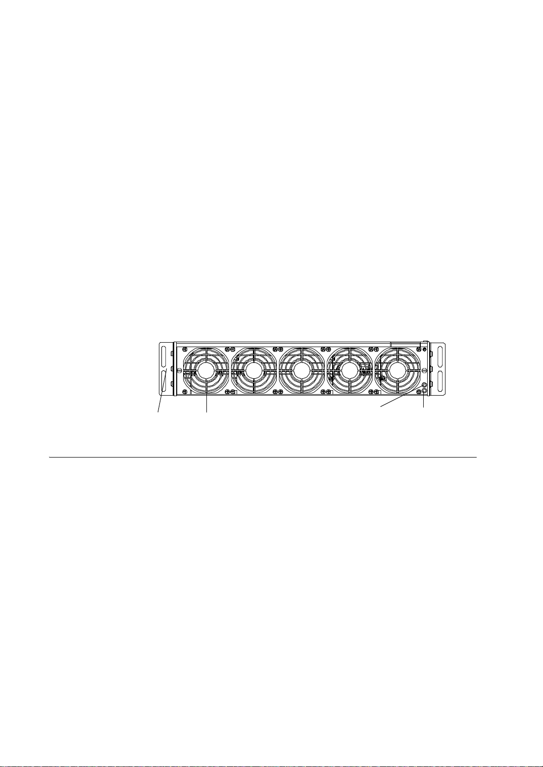
Traverse 600 Fan Assembly
One fan assembly is integrated within each Traverse 600 shelf.
The Traverse 600 fan assembly (fan card with integral shelf fan tray) cools the GCM
and service cards in the shelf. The Traverse 600 fan assembly has six fans and can force
up to 200 cubic feet per minute of cooling air. The fans draw in cooling air and push the
air through the perforated shelf.
The Traverse 600 fan assembly not only receives redundant power from the Traverse
system as a standard feature, but also provides additional controller functionality for
maximum redundancy with:
• redundant fuses for each Traverse power input (-48VA and -48VB).
• redundant inrush control circuitry to protect against power surge on startup.
• three redundant sub-circuits, each capable of supplying power for up to two fans.
Each sub-circuit has additional fuses designed to blow before the main fuses blow,
thereby ensuring that a failure in any one circuit does not affect the other two.
Figure 6 Front and Horizontal View Traverse 600 Fan Assembly
Traverse Hardware Guide, Release TR4.0.x 3
Page 26
Fan Assembly
This table lists the specifications of the fan assembly for each shelf.
Specifications
Table 7 Fan Tray and Fan Module Specifications
Parameter
Number of fans 6 5 6
Power (nominal)
Consumption (max)
Dimensions (inches)
(centimeters)
W eight fan module: 3 lb
Traverse 2000 Traverse 1600 Traverse 600
30 W 30 W 22 W
60 W 55 W 30 W
3.58 H x 21.1 W x 12.25 D 3.58 H x 17.25 W x 12.25 D 1.75 H x 6.25 W x 10.5 D
9.09 H X 53.6 W x 31.12 D 9.09 H X 43.82 W x 31.12 D 4.45 H X 15.88 W x 26.67 D
fan tray: 4 lb
fan module: 1.36 kg
fan tray: 1.81 kg
Specification
fan module: 2 lb
fan tray: 3 lb
fan module: 0.91 kg
fan tray: 1.36 kg
fan module
with integral fan tray: 2.5 lb
fan module
with integral fan tray: 1.09 kg
4 Traverse Hardware Guide, Release TR4.0.x
Page 27

Chapter 5 Power Distribution and Alarm Panels
Introduction
Force10 offers two (optional) power distribution and alarm panels (PDAP) for use with
the Traverse system: the PDAP-4S and the PDAP-15A.
Important: Carefully plan your power supply capacity. See the Planning
and Engineering Guide, Chapter 1—“Traverse Equipment Specifications,”
Power Consumption.
This chapter includes the following topics:
• PDAP-4S—for Traverse 1600 and Traverse 2000 systems
• PDAP-15A—for Traverse 600 systems
• PDAP Specifications
Traverse Hardware Guide, Release TR4.0.x 1
Page 28
PDAP-4S
TPA Fuses Alarm LEDs FlangeGMT Fuses
T
P
A
P
A
T
GMT GMT
Battery and Battery
Return “A” Supply
Battery and Battery
Return “B” Supply
Battery and Battery Return
Distribution Terminal Blocks
Chassis GroundChassis Ground
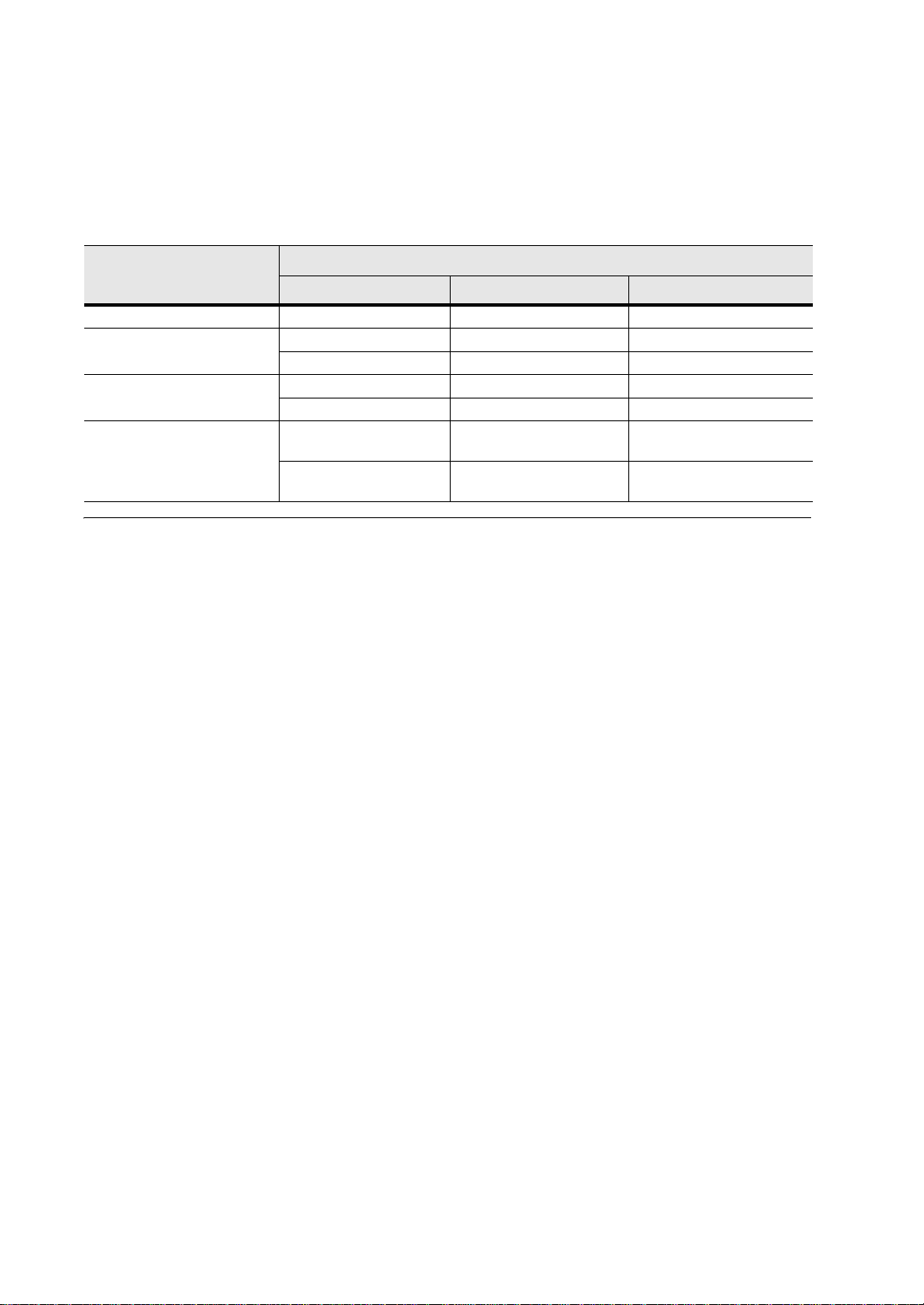
The PDAP-4S provides redundant, field replaceable 40 amp TPA fuses for up to four
Traverse shelves and GMT fuses (from 0.25 amps to 15 amps per fuse) for up to five
pieces of auxiliary equipment. The PDAP’s field replaceable fuses are accessible
without having to remove the front panel. Optional TPA fuses are available up to a
50 amp maximum.
The PDAP-4S provides visual alarm status indicators for input power, fuse power, and
critical, major, and minor bay alarms.
The PDAP-4S can be installed in a 19-inch (483 mm) or 23-inch (584 mm) telco rack.
The following illustrations show the front and rear views of the PDAP-4S.
Figure 6 PDAP-4S Fr ont View
2 Traverse Hardware Guide, Release TR4.0.x
Figure 7 PDAP-4S Rear View
Page 29
PDAP-15A
GMT Fuses
Alarm LEDs
Battery and Battery
Return “B” Supply
Battery and Battery Return
Distribution Terminal Blocks
Battery and Battery
Return “A” Supply
Chassis Ground
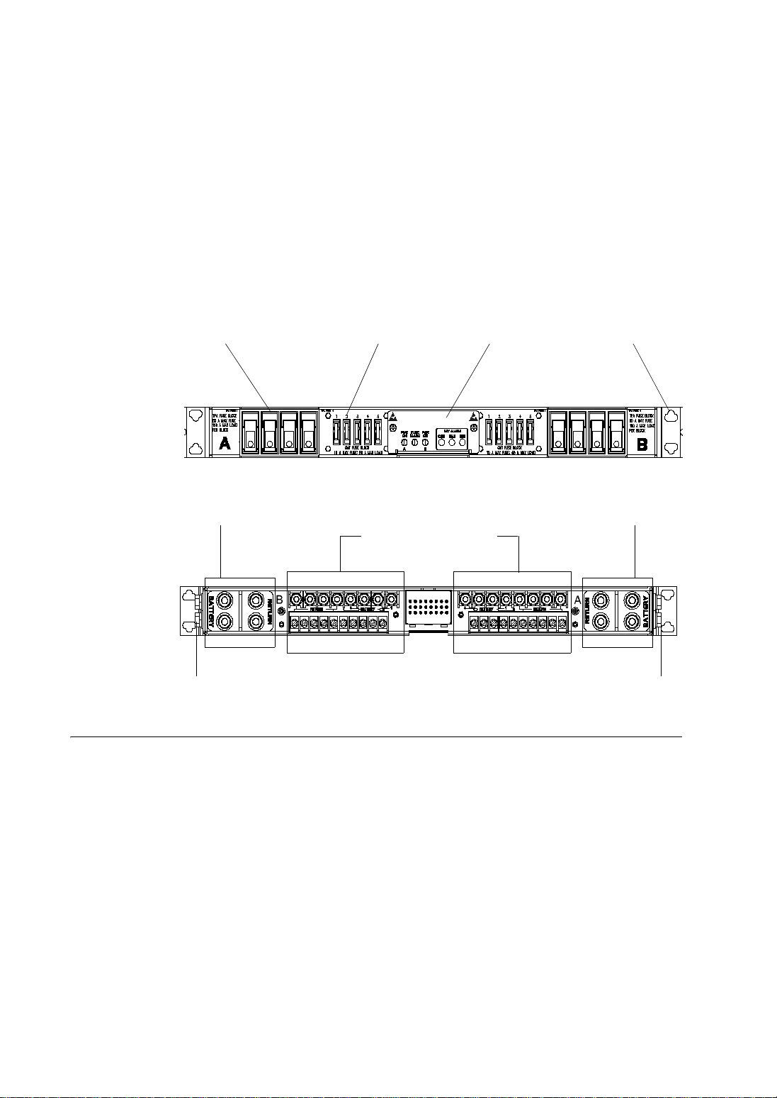
The PDAP-15A provides GMT fuses (from 0.25 amps to 15 amps per fuse) for up to
ten pieces of auxiliary equipment. The PDAP’s field replaceable fuses are accessible
without having to remove the front panel. Force10 recommends using a 3 amp fuse per
power feeder for the TE-100 and a 5 amp fuse per power feeder for the Traverse 600.
The PDAP-15A provides visual alarm status indicators for input power, fuse power,
and critical, major, and minor bay alarms.
The PDAP-15A can be installed in a 19-inch (483 mm) or 23-inch (584 mm) telco rack.
The following illustrations show the front and rear views of the PDAP-15A.
Figure 8 PDAP-15A Front View
PDAP Specifications
Figure 9 PDAP-15A Rear View
This table lists the specifications for the PDAP components.
Table 10 PDAP Specifications
Parameter
Power Consumption < 1 watts
Dimensions (inches) 1.75 H x 17.25 W x 10 D 1.75 H x 17.25 W x 10 D
(centimeters) 4.45 H x 43.82 H x 25.4 D 4.45 H x 43.82 H x 25.4 D
W eight (pounds) 14 lbs 10 lbs
(kilograms) 6.35 kg 4.5 kg
Operating Temperature/Humidity –5° C to +55° C/90%
Storage T emperature/Humidity –40° C to +70° C/95%
PDAP-4S PDAP-15A
Relative Humidity @+40° C
Specification
Relative Humidity @+28° C
–40° C to +85° C/95%
Relative Humidity @+40° C
Traverse Hardware Guide, Release TR4.0.x 3
Page 30

4 Traverse Hardware Guide, Release TR4.0.x
Page 31

Chapter 6 General Control Module (GCM) Cards
Introduction
The General Control Module (GCM) card controls and manages all Traverse cards and
services, and the fan tray. This chapter contains the following topics:
• GCM Card Description
• GCM Card Types
• Card Specifications
Note: The information in this chapter applies to the GCM part of these cards only.
For optical interface specifications, see Chapter 10—“SONET/SDH Cards.”
For VT/TU switching specifications, see Chapter 12—“VT/VC Switching Cards,”
VTX/VCX Integrated Cards.
Traverse Hardware Guide, Release TR4.0.x 1
Page 32

GCM Card Description
The GCM controls and manages all Traverse shelf cards and services, and the fan tray.
The GCM can operate by itself or with a second GCM for redundancy.
Redundant GCMs provide the following key functions:
• System initialization
• Non-stop operations
• Persistent database
• System timing
• External timing interfaces
• Alarm relay interfaces, including environmental alarm inputs and outputs.
• Craft, management, and control interfaces
• Redundant control plane and management plane (including provisioning, alarm
reporting, maintenance, and diagnostics)
Each GCM comes with 128 MB Flash and 256 MB of Synchronized Dynamic Random
Access Memory (SDRAM). On-board Flash memory provides primary storage for
system software images. It holds two software images and two configuration databases.
System firmware, software, configuration, connection, and service databases can be
downloaded into the GCM’s Flash memory for software upgrades, system
preconfiguration, connection, and service preprovisioning. The GCM’s on-board
SDRAM provides run-time storage for system firmware, software, configuration,
connection, routing, forwarding, and service databases.
A single GCM failure will not affect systems operations and services. The fault-tol erant
operating system supports non-service-affecting system software upgrade and rollback.
GCM with Integrated Optics
The GCM with integrated optics provides overall control and management functions
for the Traverse platform as well as incorporating a single or dual OC-12/STM-4 or a
single OC-48/STM-16 interface for optical trunk connectivity. This card significantly
increases the configuration flexibility of the Traverse shelf by effectively freeing up
slots for revenue-generating service interface cards.
The GCM with optics offers a true carrier-grade design supporting 1:1 redundancy for
system control and optional 1+1 APS/MSP, and UPSR/SNCP. The GCM with
OC-48/STM-16 card also supports BLSR/MS-SP Rings.
For optical interface information, see Chapter 10—“SONET/SDH Cards.”
GCM with Integrated VT/VC Switching
A VT/TU switching function is available using an integrated VTX/ VCX component on
the GCM card. For VT/TU switching information, see Chapter 12—“VT/VC
Switching Cards,” VTX/VCX Integrated Cards.
Physical Access to the Traverse
GCM’s have an RS-232 interface (DB-9) for local technician access and Command
Line Interface (CLI) support using a character-oriented terminal, such as a VT-100
terminal or a PC with terminal emulation software.
1
The serial port on the front
2 Traverse Hardware Guide, Release TR4.0.x
Page 33

faceplate of the GCM also supports hardware/firmware diagnostics and configuration
(IP address, card, and interface).
The GCM’s also have an Ethernet interface (RJ-45) with auto-sensing capability
located on the front faceplate, typically for temporary connection of a technician’s PC
laptop. One 10/100 Ethernet port is located on the front of the GCM for local technician
access. There is also a DCN 10/100 Ethernet port located on the backplane. It is
bridged to the active and standby GCM’s.
The GCM Ethernet interface is generally used for a temporary connection, but it can be
left in place to connect multiple devices to the LAN. When there are two operational
GCM cards in a Traverse node, each GCM’s Ethernet interface is active and usable for
technician access, regardless of that GCM’s active or standby status. The GCM
Ethernet interface on either the active or standby GCM can be used for CLI access as
long as the IP routing is set up correctly.
For more information on the management interface specifications, see the Traverse
Cabling and Cabling Specifications Guide, Chapter 8—“Management Interface
Specifications.” For instructions on setting IP addresses during initial commissioning,
see the Traverse Hardware Installation and Commissioning Guide,
Chapter 13—“Traverse Node Start-up and Commissioning.”
Timing Subsystem
Each GCM has a timing subsystem, which has a Stratum 3 clock, primary and
secondary T1/E1, and CC2M (Composite Clock—64KHz or 2MHz) synchronization
input and output2 interfaces. The Stratum 3 clock recovers timing from the primary or
secondary T1/E1 timing references, or any line interface, then generates and distributes
SONET/SDH-compliant clock and frame synchronization pulses to all other cards over
a dedicated timing network on the Traverse backplane. The clock supports free-run,
locked, and holdover modes of operation.
Redundant GCM’s provide 1:1 equipment protection for the timing system.
The Traverse system can distribute timing from any OC or STM interface to the timing
output ports on the rear of the shelf. The timing output ports can be set to DS1 SF, ESF,
E1 Unframed, Basic Frame, Multi-Frame, or 2.048 MHz.
The Traverse system supports synchronization-status messages (SSM) to provide
automatic re-configuration of line-timed rings, improve reliability of interoffice timing
distribution, avoid the creation of timing loops, and troubleshoot
synchronization-related problems.
For more information on the Timing interface specifications, see the Traverse Cabling
and Cabling Specifications Guide, Chapter 7—“Timing Interface Specifications.”
Alarm Interface
Each GCM has a system alarm interface, allowing it to send visual and audible system
alarms to system alarm wire-wrapped pins on the back of the Traverse shelf. The alarm
outputs are bridged between the GCM slots to provide redundancy for each alarm
indication. It can relay critical, major, and minor visual alarms to the PDAP-2S or
1
For CLI access through the GCM RS-232 interface, use the active GCM..
2
Composite Clock—64KHz (SONET) output connectors are not used.
Traverse Hardware Guide, Release TR4.0.x 3
Page 34

PDAP-4S, visual and audible alarms to third-party fuse and alarm panels, or the
gateway Traverse node.
The GCM can also send and receive additional programmable environmental alarms.
An Environmental Alarm Module (EAM), located on the back of the shelf, provides
additional environmental alarm input and output
3
capability. The Enhanced GCM,
along with the EAM, supports 16 configurable environmental alarm inputs and 8
environmental alarm outputs.
An Alarm Cut-Off (ACO) button is located on the front of the GCM to silence the
alarm buzzer and to reset timers for system maintenance alerts. When the ACO button
is pressed, its LED is turned to amber; the alarm relay is opened (disabled), but the
alarm condition still exists, and the alarm LED is maintained. A following alarm will
switch off both the ACO button and its LED, close (enable) the appropriate alarm relay ,
and switch on the matching LED.
For more information on the alarm interface specifications, see the Traverse Cabling
and Cabling Specifications Guide, Chapter 6—“Alarm Interface Specifications.”
3
Configurable environmental alarm output is not available.
4 Traverse Hardware Guide, Release TR4.0.x
Page 35

Traverse Hardware Guide, Release TR4.0.x 5
GCM Card
The Traverse supports the following GCM card types:
Types
Table 7 GCM Card Types
Model Number Card Description
• TRA-GCM-U
• TRA-GCM-VCX
• TRA-GCM-1P-OC12-IR1
• TRA-GCM-1P-OC12-LR2
• TRA-GCM-1P-OC12-IR1-VCX
• TRA-GCM-1P-OC12-LR2-VCX
• TRA-GCM-2P-OC12-IR1
• TRA-GCM-2P-OC12-LR2
• TRA-GCM-2P-OC12-IR1-VCX
• TRA-GCM-2P-OC12-LR2-VCX
• TRA-GCM-1P-OC48-SR
• TRA-GCM-1P-OC48-IR1
• TRA-GCM-1P-OC48-LR1
• TRA-GCM-1P-OC48-LR2
• TRA-GCM-1P-OC48-SR-VCX
• TRA-GCM-1P-OC48-IR1-VCX
• TRA-GCM-1P-OC48-LR1-VCX
• TRA-GCM-1P-OC48-LR2-VCX
• TRA-GCM-1P-OC48-CW1470-80K
• TRA-GCM-1P-OC48-CW1490-80K
• TRA-GCM-1P-OC48-CW1510-80K
• TRA-GCM-1P-OC48-CW1530-80K
• TRA-GCM-1P-OC48-CW1550-80K
• TRA-GCM-1P-OC48-CW1570-80K
• TRA-GCM-1P-OC48-CW1590-80K
• TRA-GCM-1P-OC48-CW1610-80K
• TRA-GCM-1P-OC48-CW1470-80K-VCX
• TRA-GCM-1P-OC48-CW1490-80K-VCX
• TRA-GCM-1P-OC48-CW1510-80K-VCX
• TRA-GCM-1P-OC48-CW1530-80K-VCX
• TRA-GCM-1P-OC48-CW1550-80K-VCX
• TRA-GCM-1P-OC48-CW1570-80K-VCX
• General Control Module card
• General Control Module card with VTX/VCX switch fabric
• GCM with 1-port OC-12 Optics-IR1/SH1, 1310 nm
• GCM with 1-port OC-12 Optics-LR2/LH2, 1310 nm
• GCM with 1-port OC-12 Optics-IR1/SH1, 1310 nm; plus VTX/VCX switch
• GCM with 1-port OC-12 Optics-LR2/LH2, 1550 nm; plus VTX/VCX switch
• GCM with 2-port OC-12/STM-4 Optics-IR1/SH1, 1310 nm
• GCM with 2-port OC-12/STM-4 Optics-LR2/LH2, 1550 nm
• GCM with 2-port OC-12/STM-4 Optics-IR1/SH1, 1310 nm; plus VTX/VCX switch
• GCM with 2-port OC-12/STM-4 Optics-LR2/LH1, 1550 nm; plus VTX/VCX switch
• GCM with 1-port OC-48/STM-16 Optics-SR1/SH1, 1310 nm
• GCM with 1-port OC-48 Optics-IR1/SH1, 1310 nm
• GCM with 1-port OC-48/STM-16 Optics-LR1/LH1, 1310 nm
• GCM with 1-port OC-48 Optics-LR2/LH2, 1550 nm
• GCM with 1-port OC-48 Optics-SR1/SH1, 1310 nm; plus VTX/VCX switch
• GCM with 1-port OC-48 Optics-IR1/SH1, 1310 nm; plus VTX/VCX switch
• GCM with 1-port OC-48 Optics-LR1/LH1, 1310 nm; plus VTX/VCX switch
• GCM with 1-port OC-48 Optics-LR2/LH2, 1550 nm; plus VTX/VCX switch
• GCM with 1-port OC-48/STM-16 Optics-CWDM-LR2/LH2, 1471 nm
• GCM with 1-port OC-48/STM-16 Optics-CWDM-LR2/LH2, 1491 nm
• GCM with 1-port OC-48/STM-16 Optics-CWDM-LR2/LH2, 1511 nm
• GCM with 1-port OC-48/STM-16 Optics-CWDM-LR2/LH2, 1531 nm
• GCM with 1-port OC-48/STM-16 Optics-CWDM-LR2/LH2, 1551 nm
• GCM with 1-port OC-48/STM-16 Optics-CWDM-LR2/LH2, 1571 nm
• GCM with 1-port OC-48/STM-16 Optics-CWDM-LR2/LH2, 1591 nm
• GCM with 1-port OC-48/STM-16 Optics-CWDM-LR2/LH2, 1611 nm
• GCM with 1-port OC-48/STM-16 Optics-CWDM-LR2/LH2, 1471 nm; plus VTX/VCX switch
• GCM with 1-port OC-48/STM-16 Optics-CWDM-LR2/LH2, 1491 nm; plus VTX/VCX switch
• GCM with 1-port OC-48/STM-16 Optics-CWDM-LR2/LH2, 1511 nm; plus VTX/VCX switch
• GCM with 1-port OC-48/STM-16 Optics-CWDM-LR2/LH2, 1531 nm; plus VTX/VCX switch
• GCM with 1-port OC-48/STM-16 Optics-CWDM-LR2/LH2, 1551 nm; plus VTX/VCX switch
• GCM with 1-port OC-48/STM-16 Optics-CWDM-LR2/LH2, 1571 nm; plus VTX/VCX switch
Page 36

Traverse Hardware Guide, Release TR4.0.x 6
Table 7 GCM Card Types
Model Number Card Description
• TRA-GCM-1P-OC48-CW1590-80K-VCX
• TRA-GCM-1P-OC48-CW1610-80K-VCX
• TRA-GCM-1P-OC48DW[–60]19-100K-A
• TRA-GCM-VCX-1P-OC48DW[19–60]- 100K-A
• TRA-UGCM-XM
• GCM with 1-port OC-48/STM-16 Optics-CWDM-LR2/LH2, 1591 nm; plus VTX/VCX switch
• GCM with 1-port OC-48/STM-16 Optics-CWDM-LR2/LH2, 1611 nm; plus VTX/VCX switch
• GCM with 1-port OC-48/STM-16 Optics-DWDM-ELR/LH, CH[19–60], [191.9–196.0] GHz
• GCM with 1-port OC-48/STM-16 Optics-DWDM-ELR/LH, CH[19–60], [191.9–196.0] GHz; plus VTX/VCX switch
• Universal GCM with Extended Memory
Page 37

Card Specifications
Specifications for all GCM types are outlined in the table below.
T able 8 GCM Specifications
Parameter Specification
Maximum number per shelf 2 (all platforms)
Technician Serial interface RS-232C DB-9 (DCE)
Technician LAN interface 10/100BaseT Ethernet RJ-45
Backplane DCN Ethernet interface 10/100BaseT Ethernet RJ-45 (on rear of shelf and shared by
active and standby GCM’s)
Backplane RS-232 interface RS-232C, 8-pin RJ-45 (DTE)
System timing Internal clock: Stratum 3
Free-run accuracy: ±4.6 x 10
(±7.1 Hz @ 1.544 MHz)
Holdover stability: <255 slips (±3.7 x 10
hours
Minimum pull-in/hold-in: ±4.6 x 10
Filtering: yes, 3 Hz
Output Phase Transients: MTIE = 1 µs
Reference: External, line, internal
Synchronization interfaces 2 T1/E1 synchronization input and output interfaces
2 CC2M synchronization input and 2M output interfaces
Alarm Interface, GCM
Visual: critical, major, minor
Audible: critical, major, minor
2 PDAP-specific auxiliary output alarm contacts
4 environmental input alarm contacts
-6
-7
) for the initial 24
-6
Alarm Interface, GCM Enhanced or
Universal
16 environmental alarm input contacts
8 environmental alarm output contacts
GCM UGCM-XM
SDRAM 256 MB 768 MB
Flash 128 MB 512 MB
Temperature range -5° C to +55° C
Power consumption 35 W, GCM
40 W, GCM Enhanced or Universal (without optics or vtx/vcx)
42 W, GCM with integrated OC-12/STM-4
46 W, GCM with integrated vtx/vcx
48 W, GCM with integrated OC-12/STM-4 plus vtx/vcx
55 W, GCM with integrated OC-48/STM-16
61 W, GCM with integrated OC-48/STM-16 plus vtx/vcx
21 W, UGCM-XM
Dimensions 13.9 H x 1.03 W x 11 D in
35.306 H x 2.616 W x 27.94 D cm
7 Traverse Hardware Guide, Release TR4.0.x
Page 38

T able 8 GCM Specifications (continued)
Parameter Specification
Weight 2.0 lbs
0.9072 kg
Industry Standards ITU-T G.703 (Table 7 and Figure 15), G.704, G.707, G.781
ANSI T1.105
GR-253-CORE, GR-1244-CORE
Jitter & W ander: ITU-T G.813 (option 1 specification)
Frame SSM: ITU-T G.704, Section 2.3.4, Table 5C and 5D
Frame: HDB3, Framed “all 1”
8 Traverse Hardware Guide, Release TR4.0.x
Page 39

Chapter 7 Next-Generation Ethernet Cards
Introduction
NGE / NGE Plus Card Description
Force10 Networks offers several versions of its single-slot next-generation Ethernet
(NGE) service interface cards with optical and electrical Gigabit Ethernet (GbE) and
electrical Fast Ethernet (FE) ports.
This chapter includes the following topics:
• NGE / NGE Plus Card Description
• NGE/NGE Plus Card Types
• NGE / NGE Plus Card Specifications
• NGE Gigabit Ethernet Ports
• GbE CWDM Wavelengths
• NGE Fast Ethernet Ports
For optical interface cabling specifications, see the Traverse Cabling and Cabling
Specifications Guide, Chapter 1—“Fiber Optic Interface Cabling Specifications.”
For electrical interface cabling specifications, see the Traverse Cabling and Cabling
Specifications Guide, Chapter 5—“Ethernet (Electrical) Interface Cabling
Specifications.”
For a summary of all optical (Ethernet and SONET/SDH) interface specifications, see
the Operations and Maintenance Guide, Chapter 19—“Traverse Transmit and Receive
Signal Levels,” Traverse Optical Interface Specifications.
NGE cards (NGE and NGE Plus) are feature-rich, full function IEEE
802.3/802.1D/802.1Q Ethernet switch cards. These cards allow the Traverse system to
support Ethernet access, aggregation, and transport services over SDH and SONET
networks, as well as offer end-user Ethernet services, such as Ethernet virtual private
line, Ethernet private line, aggregation bridge (point-to-multipoint / E-Tree), and
Ethernet bridge (E-LAN). Additionally, these Ethernet cards offer advanced traffic
management, Ethernet switching, and high and low order virtual concatenation
(HO/LO VCAT), 1:1 Ethernet electrical equipment protection on both the electrical and
optical interfaces, and Carrier Ethernet Protection Pair (CEPP) when using the NGE
Plus cards.
The NGE and NGE Plus cards have been certified as Metro Ethernet Forum (MEF)
compliant for all services (E-Line/E-LAN) to the MEF 9 technical specification.
Traverse Hardware Guide, Release TR4.0.x 1
Page 40

Virtual Concatenation
NGE cards support HO/LO VCAT and provide up to a maximum of 64 Ethernet over
SDH or SONET (EOS) trunks. It allows optical bandwidth to be tuned to the smallest
increments in SONET and SDH with the ability to provide bandwidth on demand,
enabling maximum bandwidth efficiency. Using VCAT, NGE cards map Ethernet
frames directly into a payload of N-separate non-contiguous transport paths, rather than
using the fixed contiguous concatenated transport channels.
Carrier Ethernet Protection
A CEPP is a logical pairing of two NGE Plus cards operating as one Ethernet switch to
aggregate the traffic from twice the number of physical ports (40 physical Ethernet
ports) as that of a single card. While a CEPP can use all of the physical Ethernet ports of
two cards, it uses the 64 EOS ports only of the working card for transport. CEPPs
support Link Aggregation Groups (LAGs) with ports on both cards in the CEPP. See
Link Aggregation with CEPP.
NGE Plus cards in a CEPP protection group cannot simultaneously be in a 1:1
equipment protection group; these protection groups are mutually exclusive. NGE Plus
cards not in a CEPP function as an NGE card.
Force10 recommends adjacent card configuration, although the cards can be
non-adjacent. T o create CEPP protection groups, see the T ransNav Management System
Provisioning Guide, Chapter 15—“Overview of Protection Groups.”
Link Aggregation with CEPP
CEPP supports Link Aggregation based on the IEEE 802.3ad standard. A Link
Aggregation Group (LAG) with CEPP can contain up to eight port members of the same
type (FE or GbE) from two separate NGE Plus cards. Service providers create a LAG on
the working card of the CEPP and include member ports from either of the cards in the
CEPP.
Virtual Rapid Spanning Tree Protocol (V-R STP)
On the Traverse system, up to 20 virtual copies of RSTP (V-RSTP) can be run on the
same Ethernet card. For more information on V-RSTP, see the TransNav Management
System Provisioning Guide, Chapter 48—“Rapid Spanning Tree Protocol,” Virtual
RSTP.
2 Traverse Hardware Guide, Release TR4.0.x
Page 41

NGE/NGE Plus Card Types
The Traverse supports these card types, as shown in the following two tables:
Table 8 NGE Card Types
Model Number Card Description
TRA-4GELX-16TX-HLVC 4-port GbE LX plus 16-port 10/100BaseTX
TRA-4GESX-16TX-HLVC 4-port GbE SX plus 16-port 10/100BaseTX
TRA-4GE47-53-16TX-HLVC 4-port GbE CWDM (40 km) 1471/1491/1511/1531 nm
plus 16-port 10/100BaseTX
TRA-4GE55-61-16TX-HLVC 4-port GbE CWDM (40 km) 1551/1571/1591/1611 nm
plus 16-port 10/100BaseTX
TRA-2GETX-2GELX-16TX-HLVC 2-port GbE TX plus 2-port GbE LX plus
16-port 10/100BaseTX
TRA-2PGETX-2GESX-16TX-HLVC 2-port GbE TX plus 2-port GbE SX plus 16-port
10/100BaseTX
TRA-2GESX-2GE4749-16TX-HLVC 2-port GbE CWDM plus 2-port GbE SX (40 km)
1471/1491 nm plus 16-port 10/100Base-TX
TRA-2GESX-2GE5152-16TX-HLVC 2-port GbE CWDM plus 2-port GbE SX (40 km)
1511/1531 nm plus 16-port 10/100Base-TX
TRA-2GESX-2GE5557-16TX-HLVC 2-port GbE CWDM plus 2-port GbE SX (40 km)
1551/1571 nm plus 16-port 10/100Base-TX
TRA-2GESX-2GE5961-16TX-HLVC 2-port GbE CWDM plus 2-port GbE SX (40 km)
1591/1611 nm plus 16-port 10/100Base-TX
T able 9 NGE Plus Card Types
Model Number Card Description
TRA-4GELX-16TX-HLVCCEP 4-port GbE LX plus 16-port 10/100BaseTX/CEP
TRA-4GESX-16TX-HLVCCEP 4-port GbE SX plus 16-port 10/100BaseTX/CEP
TRA-2GETX-2GELX-16TX-HLVCCEP 2-port GbE TX plus 2-port GbE LX plus
16-port 10/100BaseTX/CEP
TRA-2GETX-2GESX-16TX-HLVCCEP 2-port GbE TX plus 2-port GbE SX plus
16-port 10/100BaseTX/CEP
Traverse Hardware Guide, Release TR4.0.x 3
Page 42

NGE / NGE
Plus Card
This table lists the physical specifications for NGE and NGE Plus cards.
For GbE interface specifications, see NGE Gigabit Ethernet Ports.
Specifications
For FE interface specifications, see NGE Fast Ethernet Ports.
T able 10 NGE / NGE Plus Card Specifications
Parameter NGE NGE Plus
Maximum cards per shelf Traverse 2000: 16; Traverse 1600: 12; Traverse 600: 4
Equipment protection 1:1 Ethernet electrical and optical equipment protection
Physical interface types Optical fiber (GbE LX, SX, and CWDM);
Service interface types UNI - 802.1Q supporting tagged, untagged, and priority tagged Ethernet
Connector MPX for optical;
Bandwidth Specifications
Switching capacity
(nominal)
Concatenation Contiguous Concatenation
Transport capacity Up to 64 EOS ports
Ethernet Interface
Auto-negotiation Speed, duplex, pause control, and auto-MDIX
Loopback Facility (EOS NNI) and Terminal (UNI)
MAC addresses Up to 32,000
Mapping GFP over SONET/SDH
Maximum frame size 9,600 byte Jumbo Frames (default 1,522 bytes)
VLANs 4093 Service VLANs (S-VLANs) per EoS and
VLAN Ethertype 0x8100 (default) with an alternate of 0x9100
Maximum delay
compensation
n/a CEP
Electrical twisted pair/copper (GbE TX and 10/100BaseTX)
frames
NNI - 802.1ad / QinQ supporting double tagged Ethernet frames
Telco 50 for electrical (ECM required)
5 Gbps (2.5 Gbps full-duplex)
VT1.5 or VC-11 or VC-12
STS-1 or VC-3
STS-3c or VC-4
Virtual Concatenation
VT1.5-nv or VC-11-nv or VC-12-nv (n=1 to 64)
STS-1-nv or VC-3-nv (n=1 to 24)
STS-3c-nv or VC-4-nv (n=1 to 8)
4095 Customer VLANs (C-VLANs) per S-VLAN
64 ms
1 2
4 Traverse Hardware Guide, Release TR4.0.x
Page 43

Table 10 NGE / NGE Plus Card Specifications (continued)
Parameter NGE NGE Plus
Ethernet Services
Ethernet transport Ethernet over SONET/SDH (EOS) using GFP encapsulation,
Transport diagnostics GFP Link Integrity
Load balancing IEEE 802.3 Link Aggregation Groups (LAGs)
Spanning tree protocol RSTP and V-RSTP (separate RSTP instances per EOS)
Service protection 1+1 EOS protection on line services
n/a CEPP
Service types MEF E-Line: Ethernet private line (EPL), Ethernet virtual private line
(EVPL)
MEF E-LAN: Ethernet bridge (multipoint-to-multipoint)
Aggregate bridge (point-to-multipoint)
Traff ic Management
EVC types Point-to-Point, Multipoint-to-Multipoint and Point-to-Multipoint
Number of EVCs per EoS 4096 EVCs per EoS, 64 EoSs per card
C-VLAN/CoS preservation Full preservation of C-VLAN IDs and C-VLAN CoS (IEEE 802.1p)
Bandwidth profile types Ingress Bandwidth Profiles per UNI/NNI (port), per EVC and per Class of
Rate enforcement Single Rate (CIR) and Two Rate (CIR/PIR) Policers
Ingress classifiers C-VLAN ID, S-VLAN ID, MAC Address, IEEE 802.1p (for color-aware
Queuing/Scheduler types First in first out (FIFO) queuing for one queue
Strict priority queuing (PQ) for up to three CoSs per EOS and per Ethernet
W eighted fair queuing (WFQ) (with a minimum value of 1) for up to four
CoSs per EOS and per Ethernet UNI/NNI
Active queue management Random Early Discard (RED)
Rate shaping Supports egress rate shaping (1 to 1,000 Mbps)
Bandwidth management Configurable in 1Mbps increments per UNI/NNI (port) or per IEEE 802.1p
Color mode UNI support Both Color-aware (via IEEE 802.p) and Color-blind UNIs
Physical Specifications
Power consumption 75 W 85 W
Dimensions 13.9 H x 1.03 W x 11 D in
35.306 H x 2.616 W x 27.94 D cm
Weight 2.1 lbs
Regulatory standards NEBS: GR-63-CORE, GR-1089-CORE
Safety: UL60950, EN 60950, IEC 60950, CSA C2.22 No. 60950
EMI: FCC Part 15, Class A; EN 300 386; EN 55022, Class A
ETSI: ETS 300 019-1-3, 019-2-3 (Environmental)
Industry standards ITU -T Rec: G.7041/Y.1303 (GFP) and G.7042 (LCAS)
IEEE: 802.3ab/x(PAUSE)/z, 802.1D/Q VLAN
HO/LO VCAT, and LCAS
Service (CoS)
UNIs)
UNI/NNI
CoS Identifier
0.9525 kg
Eye Safety: Class 1
Telcordia GR-1377-CORE
MEF 9 technical specification
Traverse Hardware Guide, Release TR4.0.x 5
Page 44

1
Assumes full-duplex capacity (2.5 Gbps to the backplane and external ports), as well as a mix of frame sizes
typical of Internet traffic. The actual switching capacity is dependent on the mix of Ethernet frame sizes. See
the TransNav Management System Provisioning Guide, Chapter 52—“Ethernet Traffic Management.”
2
The full 5 Gbps switching capacity capability is limited to high order switching. For low order switching
capacity limitations, see the TransNav Management System Provisioning Guide, Chapter 27—“Configuring
SONET Services” or Chapter 29—“Configuring SDH Services.”
6 Traverse Hardware Guide, Release TR4.0.x
Page 45

NGE Gigabit Ethernet Ports
NGE and NGE Plus cards with GbE ports are based on IEEE 802.3 Ethernet
transmission standards and operate in full line rate. These cards integrate a full IEEE
802.1D Layer 2 switch and Ethernet over SONET/SDH (EOS) mapper. They can
aggregate and transport Ethernet frames in a SONET/SDH contiguous concatenation
(CCAT) or virtual concatenation (VCAT) payload. The GbE-based cards operate in
full-duplex mode and perform Layer 2 classification, Ethernet MAC and VLAN
aggregation and switching, and per-port (per UNI/NNI) and per-flow traffic
management (per Ethernet UNI/NNI, per EVC and per CoS bandwidth profiles). GbE
physical connections are either short-range (SX) optics interface, long-range (LX)
optics interface with CWDM options, or twisted-pair electrical (TX) interface.
GbE TX ports have auto-negotiation enabled and support automatic MDI (Medium
Dependent Interface) and MDI crossover (MDIX) determination. They can be
connected to either a straight-through cable or a cross-over cable. Auto-MDIX will
automatically detect and correct wiring problems such as MDIX, swapped pairs, and
reverse polarity so the user does not need to worry about having the correct Category 5
Ethernet cable type.
Specifications
This table lists the specifications for the optical and electrical GbE port interfaces:
Table 11 GbE Port Interface Specifications
Specification
Parameter
Port data rate 1 Gbps
Connector MPX Telco 50 to RJ-45
Maximum
frame size
Media type multimode fiber singlemode fiber 4 pairs, Twisted Pair
Objective
1, 2
Distance
Nominal
wavelength
Transmitter
output power
Receiver level
Guaranteed link
budget
Laser control Manual and automatic n/a
4
1
1
GbE SX GbE LX
9,600 byte Jumbo Frames (default 1,522 bytes)
0.34 mi 6.21 mi 24.85 mi 420 ft
0.55 km 10 km 40 km 128 m
850 nm 1310 nm 1471 to 1611
–10.5 to –4 dBm –10 to –3 dBm –1 to +4 dBm
–16 to –3 dBm –18 to –3 dBm –18 to 0 dBm
23
–1 PRBS, BER=10
2
5.5dB 8dB 17dB
GbE CWDM
(NGE card only)
(8 wavelengths at
20 nm spacing)
-10
GbE TX
(ECM required)
Category 5 UTP
3
n/a
1
Per IEEE 802.3z for Ethernet. Per GR-253-CORE, Issue 3, for SONET/SDH and assumes a fiber loss of
0.55 dB/km for 1310 nm or 0.275 dB/km for 1550 nm (including splices, connectors, etc.).
Traverse Hardware Guide, Release TR4.0.x 7
Page 46

2
Force10 recommends customers take actual fiber readings, as these values are based on standards
qualification.
3
For valid wavelengths, see GbE CWDM Wavelengths.
4
These values account for the connector loss from connection to the optical interface and the worst case
optical path penalty.
GbE CWDM Wavelengths
The following NGE cards offer the ITU-T G.694.2 CWDM optical transceivers on the
GbE interfaces with a 20 nm spacing between wavelengths, from 1471 nm to 1611 nm.
Note: The CWDM optical transceivers do not apply to the NGE Plus card.
Table 12 GbE LX CWDM Wavelengths to Port Assignments
NGE Card Port Typical TX
4-port GbE CWDM (40 km) 1471/1491/1511/1531 plus
16-port 10/100BaseTX
4-port GbE CWDM (40 km) 1551/1571/1591/1611 plus
16-port 10/100BaseTX
2-port GbE SX plus 2-port GbE CWDM (40 km)
1471/1491 plus 16-port 10/100BaseTX
2-port GbE SX plus 2-port GbE CWDM (40 km)
1511/1531 plus 16-port 10/100BaseTX
2-port GbE SX plus 2-port GbE CWDM (40 km)
1551/1571 plus 16-port 10/100BaseTX
2-port GbE SX plus 2-port GbE CWDM (40 km)
1591/1611 plus 16-port 10/100BaseTX
Wavelength
(nm)
1 1471 1464.5 to 1477.5
2 1491 1484.5 to 1497.5
3 1511 1504.5 to 1517.5
4 1531 1524.5 to 1537.5
1 1551 1544.5 to 1557.5
2 1571 1564.5 to 1577.5
3 1591 1584.5 to 1597.5
4 1611 1604.5 to 1617.5
3 1471 1464.5 to 1477.5
4 1491 1484.5 to 1497.5
3 1511 1504.5 to 1517.5
4 1531 1524.5 to 1537.5
3 1551 1544.5 to 1557.5
4 1571 1564.5 to 1577.5
3 1591 1584.5 to 1597.5
4 1611 1604.5 to 1617.5
TX Wavelength
Range (nm)
NGE Fast Ethernet Ports
The NGE and NGE Plus cards with fast Ethernet (10/100BaseTX) ports are based on
IEEE 802.3 Ethernet transmission standards and operate in full line rate. These cards
integrate a full IEEE 802.1D Layer 2 switch and Ethernet over SONET/SDH (EOS)
mapper. They can aggregate and transport Ethernet frames in a SONET/SDH
contiguous concatenation (CCAT) or virtual concatenation (VCAT) payload. The
FE-based cards operate in full-duplex (or half-duplex) mode and perform Layer 2
classification, Ethernet MAC and VLAN aggregation and switching, and per-port (per
UNI/NNI) and per-flow traffic management (per Ethernet UNI/NNI, per EVC, and per
CoS bandwidth profiles).
Each 10/100BaseTX port provides auto-negotiation and supports automatic MDI
(Medium Dependent Interface) and MDI-X determination. They can be connected to
either a straight-through cable or a cross-over cable. Auto-MDIX will automatically
detect and correct wiring problems such as MDI crossover, swapped pairs, and reverse
polarity so the user does not need to worry about having the correct Category-5
Ethernet cable type.
8 Traverse Hardware Guide, Release TR4.0.x
Page 47

Specifications
This table lists the specifications for the electrical fast Ethernet (FE) port interface:
T able 13 Fast Ethernet (10/100BaseTX) Card Specifications
Parameter Specification (FE TX)
Port data rate 10 or 100 Mbps
Connector Telco 50 to RJ-45
(ECM required)
Media type 2 pairs, Twisted Pair Category 5 UTP
Maximum reach
Maximum frame size 9,600 byte Jumbo Frames (default 1,522 bytes)
Peak differential signal amplitude 10 Mbps = 4.0 V
420 ft
128 m
100 Mbps = 2.0 V
Traverse Hardware Guide, Release TR4.0.x 9
Page 48

10 Traverse Hardware Guide, Release TR4.0.x
Page 49

Chapter 8 Gigabit Ethernet-only Cards (Dual-slot)
Introduction
Force10 Networks offers a variety of dual-slot Gigabit Ethernet-only (GbE) service
interface cards to support higher bandwidth and port density Ethernet applications and
services: bandwidth-intensive Ethernet Private Lines (EPL), Multipoint Layer 2 V irtual
Private Networks (VPNs), Internet Protocol Television (IPTV), and other IP-centric
video applications.
Dual-slot GbE cards with GbE ports are based on IEEE 802.3 Ethernet transmission
standards and operate in full line rate. These cards integrate a full IEEE 802.1D Layer 2
switch and Ethernet over SONET/SDH (EOS) mapper. They can aggregate and
transport Ethernet frames in a SONET/SDH contiguous concatenation (CCAT) or
virtual concatenation (VCAT) payload. The GbE-based cards operate in full-duplex
mode and perform Layer 2 classification, Ethernet MAC and VLAN aggregation and
switching, and per-port (per UNI/NNI) and per-flow traffic management (per Ethernet
UNI/NNI, per Ethernet virtual circuit (EVC) and per class of service (CoS) bandwidth
profiles).
The 1-port 10GbE card provides an integral 802.3ae-compliant XFP (10 Gigabit Small
Form Factor Pluggable) interface that can be ordered with LR, ER, or ZR optics. The
10-port GbE (GbE-10) card provides up to ten 802.3z-compliant optical or electrical
GbE ports of customer-installable Small Form Factor Pluggable optics (SFPs) using an
SFP connector card (SCM). The SFPs can be in any mix of pluggable SFP-based
1000Base-SX, -LX, or -ZX optical or 1000Base-TX electrical interfaces.
This chapter includes the following topics:
• 1-Port 10GbE Card
• 10-Port GbE Card
• Comparing Gigabit Ethernet Payload Capacity
For optical interface cabling specifications, see the Traverse Cabling and Cabling
Specifications Guide, Chapter 1—“Fiber Optic Interface Cabling Specifications.”
For electrical interface cabling specifications, see the Traverse Cabling and Cabling
Specifications Guide, Chapter 5—“Ethernet (Electrical) Interface Cabling
Specifications.”
For a summary of all optical (Ethernet and SONET/SDH) interface specifications, see
the Operations and Maintenance Guide, Chapter 19—“Traverse Transmit and Receive
Signal Levels.”
Traverse Hardware Guide, Release TR4.0.x 1
Page 50

1-Port 10GbE Card
The 1-port 10GbE (10GbE) card supports high capacity Ethernet switching and provides
a comprehensive set of features to enable the Traverse platform to support evolution to
an end-to-end Carrier Ethernet transport Ethernet infrastructure. The 10GbE is ideal for
10GbE Metropolitan/Wide Area Network (MAN/WAN) core and inter-carrier handoff
applications.
Each card integrates 20 Gbps of non-blocking Layer 2 (L2)s Ethernet switching into the
Traverse shelf. Advanced IEEE 802.ad Provider Bridging capabilities include support
for 802.1Q Customer Virtual Local Area Networks (C-VLANs) and Service VLANs
(S-VLANs) (Q-in-Q) with granular traffic policing and shaping to support differentiated
service classes and guaranteed service level agreements (SLAs).
The 10GbE card supports the Metro Ethernet Forum’s (MEF’s) Ethernet Private Line
(EPL), Ethernet Virtual Private Line (EVPL), E-LAN (Ethernet multipoint-tomultipoint), and E-Tree (point-to-multipoint) service definitions. Additionally, these
Ethernet cards offer advanced traffic management, Ethernet switching (including
VLAN, High Order Virtual Concatenation (HO VCAT) and Link Capacity Adjustment
Scheme (LCAS), and 1:1 Ethernet optical equipment protection.
Use the dual-slot, hot-swappable 10GbE card in any combination of the available
interface slots of the Traverse 2000 or Traverse 1600 shelves. Physical access to the
optical interface is through an MPX connector with singlemode fiber on the back of the
shelf.
Virtual Concatenation
The 1-port 10GbE card supports HO VCAT and provides up to a maximum of 128
Ethernet over SDH or SONET (EOS) network to network interfaces (NNIs) (i.e.,
trunks). It allows optical bandwidth to be tuned to the smallest increments in SONET
and SDH with the ability to provide bandwidth on demand, enabling maximum
bandwidth efficiency. Using VCAT, 10GbE cards map Ethernet frames directly into a
payload of N-separate non-contiguous transport paths (where N=192), rather than using
the fixed contiguous concatenated transport channels.
Virtual Rapid Spanning Tree Protocol (V-R STP)
On the Traverse system, up to 20 virtual copies of RSTP (V-RSTP) can be run on the
same Ethernet card. Each copy, called a Virtual RSTP Bridge (VRB), uses an exclusive
set of EOS ports that terminate on the card. For more information, see the TransNav
Management System Provisioning Guide, Chapter 48—“Rapid Spanning Tree
Protocol,” Virtual RSTP.
Card Types
The Traverse supports these cards:
T able 9 10GbE Card Types
Model Number Card Description
TRA-1P-10GE-LR-SMF 1-port 10GbE card,10GBASE-LR, 1310 nm SMF
TRA-1P-10GE-ER-SMF 1-port 10GbE card, 10GBASE-ER, 1550 nm SMF
TRA-1P-10GE-ZR-SMF 1-port 10GbE card, 10GBASE-ZR, 1550 nm SMF
2 Traverse Hardware Guide, Release TR4.0.x
Page 51

Card Specifications
This table lists the physical specifications for 10GbE cards.
Table10 10GbE Card Specifications
Parameter
Maximum cards per shelf Traverse 2000: 9; Traverse 1600: 7
Equipment protection 1:1 Ethernet optical equipment protection (requires an optical splitter/coupler)
Physical interface types Optical fiber (10GbE LR, ER, and ZR)
Service interface types UNI - 802.1Q supporting tagged, untagged, and priority tagged Ethernet frames
Bandwidth Specifications
Switching capacity
(nominal)
1
Concatenation Contiguous Concatenation
Transport capacity Up to 128 EOS ports
Ethernet Interface
Port data rate 10 Gbps
Connector
2
Maximum frame size 9,600 byte Jumbo Frames (default 1,522 bytes)
Media type Singlemode fiber (SMF)
Distance Objective
3, 4
Nominal wavelength 1310 nm 1550 nm 1550 nm
Transmitter output power
Receiver level –11.6 to 0.5 dBm –13 to -1 dBm -23 to -7 dBm
Guaranteed link budget 4.4 dB 11 dB 22 dB
Laser control Manual and automatic
Auto-negotiation (speed,
duplex, and pause)
Loopback Facility (EOS NNI) and Terminal (UNI)
MAC addresses Up to 32,000
Mapping GFP over SONET/SDH
Maximum frame size 9,600 byte Jumbo Frames (default 1,522 bytes)
6
VLANs
VLAN Ethertype
7
Maximum delay
compensation
(TRA-1P-10GE-LR-SMF)
5
10GBaseLR
10GBaseER
(TRA-1P-10GE-ER-SMF)
10GBaseZR
(TRA-1P-10GE-ZR-SMF)
NNI - 802.1ad / QinQ supporting double tagged Ethernet frames
20 Gbps (10 Gbps full-duplex)
STS-1 or (HO) VC-3
STS-3c or VC-4
Virtual Concatenation
STS-1-nv or VC-3-nv (n=1 to 192)
STS-3c-nv or VC-4-nv (n=1 to 64)
MPX (Connect to housing B)
6.2 mi 24.85 mi 49.71 mi
10 km 40 km 80 km
–7.2 to 0.5dBm –2 to2dBm -1 to 4dBm
23
–1 PRBS, BER=10
2
-10
Not available
4093 Service VLANs (S-VLANs) per EoS and
4093 Customer VLANs (C-VLANs) per S-VLAN
0x8100 (default) with an alternate of 0x9100
128 ms
Traverse Hardware Guide, Release TR4.0.x 3
Page 52

T able 10 10GbE Card Specifications (continued)
Parameter
Ethernet Services
Ethernet transport Ethernet over SONET/SDH (EOS) using GFP encapsulation,
Transport diagnostics GFP Link Integrity
Load balancing IEEE 802.3 Link Aggregation Groups (LAGs)
Spanning tree protocol RSTP and V-RSTP (separate RSTP instances per EOS)
Service types MEF E-Line: Ethernet private line (EPL), Ethernet virtual private line (EVPL)
Tra ffic Management
EVC types Point-to-Point, Multipoint-to-Multipoint and Point-to-Multipoint
Number of EVCs per EoS 4093 EVCs per EoS, 128 EoSs per card
C-VLAN/CoS preservation Full preservation of C-VLAN IDs and C-VLAN CoS (IEEE 802.1p)
Bandwidth profile types Ingress Bandwidth Profiles per UNI/NNI (port) , per EVC and per Class of Service
Rate enforcement Single Rate (CIR) and Two Rate (CIR/PIR) Policers
Ingress classifiers C-VLAN ID, S-VLAN ID, MAC Address, IEEE 802.1p (for color-aware UNIs)
Queuing/Scheduler types First in first out (FIFO) queuing for one queue
Active queue management Random Early Discard (RED)
Rate shaping Supports egress rate shaping (1 to 10,000 Mbps)
Bandwidth management Configurable in 1Mbps increments per UNI/NNI (port) or per IEEE 802.1p CoS
Color mode UNI support Both Color-aware (via IEEE 802.p) and Color-blind UNIs
Physical Specifications
Power consumption 125 W nominal
Temperature -5° C to +55° C
Dimensions 13.9 H x 2.06 W x 11 D i n
Weight 4.2 lbs
Regulatory standards NEBS: GR-63-CORE, GR-1089-CORE
Industry standards ITU -T Rec: G.7041/Y.1303 (GFP) and G.7042 (LCAS)
10GBaseLR
(TRA-1P-10GE-LR-SMF)
MEF E-LAN: Ethernet bridge (multipoint-to-multipoint), Aggregate bridge
Strict priority queuing (PQ) for up to three CoSs per EOS and per Ethernet UNI/NNI
W eighted fair queuing (WFQ) (with a minimum value of 1) for up to four CoSs per
Safety: UL60950, EN 60950, IEC 60950, CSA C2.22 No. 60950
EMI: FCC Part 15, Class A; EN 300 386; EN 55022, Class A
ETSI: ETS 300 019-1-3, 019-2-3 (Environmental)
IEEE: 802.3ab/3ae, 802.1ad/1D/1p/1Q/ad/p VLAN
10GBaseER
(TRA-1P-10GE-ER-SMF)
HO VCAT, and LCAS
(point-to-multipoint)
(CoS)
EOS and per Ethernet UNI/NNI
Identifier
(140 W max)
35.306 H x 5.232 W x 27.94 D cm
1.9051 kg
Eye Safety: Class 1
Telcordia GR-1377-CORE
MEF 9 technical specification
10GBaseZR
(TRA-1P-10GE-ZR-SMF)
4 Traverse Hardware Guide, Release TR4.0.x
Page 53

1
Assumes full-duplex capacity (10 Gbps to the backplane and external ports), as well as a mix of frame sizes typical of
Internet traffic. The actual switching capacity is dependent on the mix of Ethernet frame sizes. See the TransNav
Management System Provisioning Guide, Chapter 52—“Ethernet Traffic Management.”
2
For installation specifications, see the Traverse Cabling and Cabling Specifications Guide, Chapter 1—“Fiber Optic
Interface Cabling Specifications.”.
3
Per IEEE 802.3-2005 for Ethernet and assumes a fiber loss of 0.4 dB/km for 1330 m, pr 0.25 dB/km for 1550 nm
(including splices, connectors, etc.). Per GR-253-CORE, Issue 3, for SONET/SDH and assumes a fiber loss of
0.55 dB/km for 1310 nm or 0.275 dB/km for 1550 nm (including splices, connectors, etc.).
4
Force10 recommends customers take actual fiber readings, as these values are based on standards qualification.
5
These values account for the connector loss from connection to the optical interface and the worst case optical path
penalty.
6
Of the 4096 possible VLAN values, values 1 through 4093 are valid VLAN IDs. The value 0 identifies priority frames
meaning the packet contains priority information, but no VLAN ID. Values 4094 and 4095 are reserved for system use.
7
On 10GbE or GbE-10 cards, the system distinguishes between incoming and outgoing tags. These cards recognize only a
single VLAN Ethertype on any port. If the corresponding port Ethertype parameter is disabled, then incoming tags must
have 0x8100 Ethertype. If the corresponding port Ethertype parameter is enabled, then outgoing tags must match the
setting of the card parameter.
Traverse Hardware Guide, Release TR4.0.x 5
Page 54

10-Port GbE Card
The 10-port GbE (GbE-10) card supports high density Ethernet switching and provides
a comprehensive set of features to enable the Traverse platform to support evolution to
an end-to-end Carrier Ethernet transport Ethernet infrastructure. Each card integrates
20 Gbps of non-blocking L2 Ethernet switching into the Traverse shelf. Advanced
IEEE 802.ad Provider Bridging capabilities include support for 802.1Q C-VLANs and
S-VLANs (Q-in-Q) with granular traffic shaping to support differentiated service
classes and guaranteed SLAs.
Virtual Concatenation
GbE-10 cards support HO/LO VCAT and provide up to a maximum of 128 Ethernet
over SDH or SONET (EOS) trunks. It allows optical bandwidth to be tuned to the
smallest increments in SONET and SDH with the ability to provide bandwidth on
demand, enabling maximum bandwidth efficiency. Using VCAT, GbE-10 cards map
Ethernet frames directly into a payload of N-separate non-contiguous (where N=192)
transport paths, rather than using the fixed contiguous concatenated transport channels.
Virtual Rapid Spanning Tree Protocol (V-R STP)
On the Traverse system, up to 20 virtual copies of RSTP (V-RSTP) can be run on the
same Ethernet card. For more information on V-RSTP, see the TransNav Management
System Provisioning Guide, Chapter 48—“Rapid Spanning Tree Protocol,” Virtual
RSTP.
Card Type
The Traverse supports this card type:
Important: This card must be ordered with a 10-port SFP connector
module (SCM). See Table 13 10-port GbE SFP Module Connector
Module Type.
T able 11 10-port GbE Card Type
Model Number Card Description
TRA-10P-1GE-SFP 10-port 1GbE card, no optics
10-port GbE SFP Types
The Traverse supports these customer-installable SFP types:
Table12 10-port GbE Card SFP Types
Model Number SFP Description
SFP-1000BASE-SX850 1000Base-SX SFP, MMF, 850nm (customer installable)
SFP-1000BASE-LX1310 1000Base-LX SFP, SMF, 1310nm (customer installable)
SFP-1000BASE-ZX1550 1000Base-ZX SFP, SMF, 1550nm (customer installable)
SPF-1000BASE-TX 1000Base-TX SFP, Copper, RJ-45 connector (customer installable)
Connector Module Type
The Traverse supports this connector module type:
T able 13 10-port GbE SFP Module Connector Module Type
Model Number Module Description
CONNECTOR-10P-SFP 2-slot-wide, 10-Port SFP connector module (SCM) for 10-port
1GbE card (TRA-10P-1GE-SFP)
6 Traverse Hardware Guide, Release TR4.0.x
Page 55

Specifications
This table lists the physical specifications for GbE-10 cards.
For additional specifications of each physical GbE interface types available, see
GbE-10 Gigabit Ethernet Ports.
T a ble 14 10-port GbE Card Specifications
Parameter
Maximum cards per
Traverse 2000: 8; Traverse 1600: 6
shelf
Equipment
1:1 Ethernet optical equipment protection; requires an optical splitter/coupler
protection
Physical interface
types
Service interface
types
UNI - 802.1Q supporting tagged, untagged, and priority tagged Ethernet frames
NNI - 802.1ad / QinQ supporting double tagged Ethernet frames
Optical fiber (GbE SX, LX, and ZX)
Electrical twisted pair/copper (GbE TX)
Bandwidth Specifications
Switching capacity
(nominal)
1
20 Gbps (10 Gbps full-duplex)
Concatenation Contiguous Concatenation
STS-1-nv or VC-3-nv (n=1 to 192)
STS-3c-nv or VC-4-nv (n=1 to 64)
Transport capacity Up to 128 EOSs
Ethernet Interface
Port data rate 10 Gbps
Connector
2
SFP with Duplex LC (SCM required)
SFP with RJ-45 for GbE TX (SCM required)
Maximum frame
9,600 byte Jumbo Frames (default 1,522 bytes)
size
Laser control Manual and automatic
Auto-negotiation
(speed, duplex, and
pause)
Speed set to 10 Gbps, duplex set to FULL DUPLEX,
and pause receive only is provisionable
(SFP auto-MDIX support only)
Loopback Facility (EOS NNI) and Terminal (UNI)
MAC addresses Up to 32,000
Mapping GFP over SONET/SDH
Maximum frame
9,600 byte Jumbo Frames (default 1,522 bytes)
size
VLANs
3
4093 Service VLANs (S-VLANs) per EoS and
4093 Customer VLANs (C-VLANs) per S-VLAN
VLAN Ethertype
4
0x8100 (default) with an alternate of 0x9100
Maximum delay
compensation
Ethernet Services
Ethernet transport Ethernet over SONET/SDH (EOS) using GFP encapsulation,
GbE-10
(TRA-10P-1GE-SFP)
STS-1 or VC-3
STS-3c or VC-4
Virtual Concatenation
128 ms
HO/LO VCAT, and LCAS
Traverse Hardware Guide, Release TR4.0.x 7
Page 56

Table 14 10-port GbE Card Specifications (continued)
Parameter
Transport
diagnostics
Load balancing IEEE 802.3 Link Aggregation Groups (LAGs)
Spanning tree
protocol
Service types MEF E-Line: Ethernet private line (EPL), Ethernet virtual private line (EVPL)
Traffic Management
EVC types Point-to-Point, Multipoint-to-Multipoint and Point-to-Multipoint
Number of EVCs
per EoS
C-VLAN/CoS
preservation
Bandwidth profile
types
Rate enforcement Single Rate (CIR) and Two Rate (CIR/PIR) Policers
Ingress classifiers C-VLAN ID, S-VLAN ID, MAC Address, IEEE 802.1p (for color-aware UNIs)
Queuing/Scheduler
types
Active queue
management
Rate shaping Supports egress rate shaping (1 to 10,000 Mbps)
Bandwidth
management
Color mode UNI
support
Physical Specifications
Power consumption 115 W nominal
Temperature -5° C to +55° C
Dimensions 13.9 H x 2.06 W x 11 D in
Weight 4.2 lbs
Regulatory
standards
Ingress Bandwidth Profiles per UNI/NNI (port), per EVC and per Class of Service
Strict priority queuing (PQ) for up to three CoSs per EOS and per Ethernet UNI/NNI
W eighted fair queuing (WFQ) for up to four CoSs per EOS and per Ethernet UNI/NNI
Configurable in 1 Mbps increments per UNI/NNI (port) or per IEEE 802.1p CoS
RSTP and V-RSTP (separate RSTP instances per EOS)
MEF E-LAN: Ethernet bridge (multipoint-to-multipoint)
Aggregate bridge (point-to-multipoint)
4093 EVCs per EoS, 64 EoSs per card
Full preservation of C-VLAN IDs and C-VLAN CoS (IEEE 802.1p)
First in first out (FIFO) queuing for one queue
Random Early Discard (RED)
Both Color-aware (via IEEE 802.p) and Color-blind UNIs
35.306 H x 5.232 W x 27.94 D cm
NEBS: GR-63-CORE, GR-1089-CORE
Safety: UL60950, EN 60950, IEC 60950, CSA C2.22 No. 60950
EMI: FCC Part 15, Class A; EN 300 386; EN 55022, Class A
ETSI: ETS 300 019-1-3, 019-2-3 (Environmental)
GbE-10
(TRA-10P-1GE-SFP)
GFP Link Integrity
(CoS)
Identifier
(130 W max)
1.9051 kg
Eye Safety: Class 1
8 Traverse Hardware Guide, Release TR4.0.x
Page 57

Table 14 10-port GbE Card Specifications (continued)
Parameter
Industry standards ITU -T Rec: G.7041/Y.1303 (GFP) and G.7042 (LCAS)
IEEE: 802.3ab/z, 802.1ad/1D/1p/1Q/p
MEF 9 technical specification
1
Assumes full-duplex capacity (10 Gbps to the backplane and external ports), as well as a mix of frame sizes
typical of Internet traffic. The actual switching capacity is dependent on the mix of Ethernet frame sizes. See the
TransNav Management System Provisioning Guide, Chapter 52—“Ethernet Traffic Management.”
2
For installation specifications, see the Traverse Cabling and Cabling Specifications Guide, Chapter 1—“Fiber
Optic Interface Cabling Specifications.”
3
Of the 4096 possible VLAN values, values 1 through 4093 are valid VLAN IDs. The value 0 identifies priority
frames meaning the packet contains priority information, but no VLAN ID. Values 4094 and 4095 are reserved
for system use.
4
On 10GbE or GbE-10 cards, the system distinguishes between incoming and outgoing tags. These cards
recognize only a single VLAN Ethertype on any port. If the corresponding port Ethertype parameter is disabled,
then incoming tags must have 0x8100 Ethertype. If the corresponding port Ethertype parameter is enabled, then
outgoing tags must match the setting of the card parameter.
GbE-10
(TRA-10P-1GE-SFP)
Telcordia GR-1377-CORE
GbE-10 Gigabit Ethernet Ports
GbE-10 cards with GbE ports are based on IEEE 802.3 Ethernet transmission standards
and operate in full line rate. These cards integrate a full IEEE 802.1D Layer 2 switch
and Ethernet over SONET/SDH (EOS) mapper. They can aggregate and transport
Ethernet frames in a SONET/SDH contiguous concatenation (CCAT) or virtual
concatenation (VCAT) payload. The GbE-based cards operate in full-duplex mode and
perform Layer 2 classification, Ethernet MAC and VLAN aggregation and switching,
and per-port (per UNI/NNI) and per-flow traffic management (per Ethernet UNI/NNI,
per EVC and per CoS bandwidth profiles). GbE-10 physical interfaces are either
short-range (SX), long-range (LX), (ZX), or twisted-pair electrical (TX) optical
connections.
GbE-10 card GbE TX ports have auto-negotiation “forced” with speed set to 10 Gbps
and duplex set to FULL DUPLEX. Manual Pause, Advertise 1000M Full Duplex,
and Advertised P AUSE RX are provisionable. Through the Manual Pause paramete r ,
Forced Pause Receive is provisionable and Forced Pause Transmit is disabled.
Advertised PAUSE TX is disabled.
Important: Force10 recommends that if the peer device is 802.3
compliant, the operator leave the Auto-negotiation feature Enabled.
Traverse Hardware Guide, Release TR4.0.x 9
Page 58

Specifications
This table lists the specifications for the optical and electrical GbE port interfaces:
T able 15 GbE Port Interface Specifications
Specification
Parameter
Port data rate 1 Gbps
Connector SFP LC
Maximum
frame size
Media type Multi-mode fiber (SX) Single mode fiber (LX and ZX) 4 pairs, Twisted Pair
Objective
1, 2
Distance
Nominal
wavelength
Transmitter
output power
Receiver level
Guaranteed link
budget
3
1
1
Laser control Manual and automatic n/a
GbE SX
(SFP-1000BASE-SX850)
(SFP-1000BASE-LX1330)
GbE LX
GbE ZX
(SFP-1000BASE-ZX1550)
(SCM required)
9,600 byte Jumbo Frames (default 1,522 bytes)
0.34 mi 6.21 mi 49.71 mi 328 ft
0.55 km 10 km 80 km 100 m
850 nm 1310 nm 1550 nm
–10.5 to –4 dBm –10 to –3 dBm -1 to -5 dBm
–16 to –3 dBm –18 to –3 dBm -22 to -3 dBm
23
–1 PRBS, BER=10
2
-10
5.5 dB 8 dB 21
GbE TX
(SFP-1000BASE-TX)
RJ-45
(SCM required)
Category 5 UTP
n/a
1
Per IEEE 802.3-2005 for Ethernet and assumes a fiber loss of 0.4 dB/km for 1330 m, pr 0.25 dB/km for 1550 nm (including splices,
connectors, etc.). Per GR-253-CORE, Issue 3, for SONET/SDH and assumes a fiber loss of 0.55 dB/km for 1310 nm or 0.275 dB/km
for 1550 nm (including splices, connectors, etc.).
2
Force10 recommends customers to take actual fiber readings, as these values are based on standards qualification.
3
These values account for the connector loss from connection to the optical interface and the worst case optical path penalty.
10 Traverse Hardware Guide, Release TR4.0.x
Page 59

Comparing Gigabit Ethernet Payload Capacity
Different concatenation methods on the Gigabit Ethernet (10GbE and GBE-10) cards
result in different throughput for payload traffic. See the following table for a basic
summary of the differences.
Table 16 Co mparing Gigabi t Eth e rn et Payload Capacity
SONET SDH Type
VT-1.5-Xv SPE VC-11-Xv Low Order X x 1.600 (X = 1 to 64)
VT-2-Xv-SPE VC-12-Xv Low Order X x 2.176 (X = 1 to 64)
N/A VC-3-Xv Low Order X x 48.384 (X = 1 to 256)
STS-1-Xv SPE VC-3-Xv High Order X x 48.384 (X = 1 to 256)
STS-3c-Xv SPE VC-4-Xv High Order X x 149.76 (X = 1 to 256)
Payload Capacity
(Mbit/s)
Traverse Hardware Guide, Release TR4.0.x 11
Page 60

12 Traverse Hardware Guide, Release TR4.0.x
Page 61

Chapter 9 Ethernet Over PDH Cards
Introduction
Force10 Networks offers several versions of its single-slot Ethernet over PDH
(Plesiochronous Digital Hierarchy) service interface cards with optical and electrical
Gigabit Ethernet (GbE) and electrical Fast Ethernet (FE) ports.
The EoPDH Service Interface Modules (SIMs) for the Traverse® multiservice
switching and transport platform position Force10 with the industry’s leading solution
for multiservice transport with Ethernet service delivery over fiber and copper PDH
access networks. The Traverse platform supports any combination of Ethernet,
SONET/SDH, or TDM circuit grooming, switching and transport in a single shelf. This
versatility enables network operators to leverage their existing infrastructure as they
transition to a multiservice, Carrier Ethernet network at their desired pace.
This chapter includes the following topics:
• EoPDH Card
• Gigabit Ethernet Ports on EoPDH Cards
• EoPDH Fast Ethernet Ports
For optical interface cabling specifications, see the Traverse Cabling and Cabling
Specifications Guide, Chapter 1—“Fiber Optic Interface Cabling Specifications.”
For electrical interface cabling specifications, see the Traverse Hardware Guide,
Chapter 8—“Gigabit Ethernet-only Cards (Dual-slot).”
For a summary of all optical (Ethernet and SONET/SDH) interface specifications, see
the Operations and Maintenance Guide, Chapter 19—“Traverse Transmit and Receive
Signal Levels.”
Traverse Hardware Guide, Release TR4.0.x 1
Page 62

EoPDH Card
EoPDH cards, equivalent to the NGE Plus cards in most ways and more, are
feature-rich, full function IEEE 802.3/802.1D/802.1Q Ethernet switch cards. These
cards allow the Traverse system to support Ethernet access, aggregation, and transport
services over SDH and SONET networks, as well as offer end-user Ethernet services
such as Ethernet virtual private line, Ethernet private line, aggregation bridge
(point-to-multipoint / E-Tree), and Ethernet bridge (E-LAN). Additionally, these
Ethernet cards offer advanced traffic management, Ethernet switching, and high and
low order virtual concatenation (HO/LO VCAT), 1:1 Ethernet electrical equipment
protection on both the electrical and optical interfaces, and Carrier Ethernet Protection
Pair (CEPP).
This card supports all of the same applications as the NGE Plus card -- Ethernet
services involving GbE, FE, and EOS ports with optional CEPP protection. In addition,
this card supports Ethernet access using EoPDH technology in which an Ethernet
signal is carried in GFP-encapsulated frames over a virtually concatenated group of
DS1 / E1 / DS3 / E3 circuits. Ethernet over PDH is similar to Ethernet over SONET /
SDH, just with a different physical layer transport.
The EoPDH cards also are ITU conformant to carry GFP-encapsulated Ethernet frames
over EoPDH trunks consisting of virtually concatenated PDH circuits.
EoPDH cards bring Ethernet frames to a Traverse node for switching and forwarding
on a transport network. EoPDH is an access technology; the transport technology is
Ethernet over SONET/SDH.
Card Types
The Traverse supports the card types shown in these two tables:
Table10 EoPDH Card Types
Model Number Card Description
TRA-EOPDH-4GELX-16TX 4-port GbE LX plus 16-port 10/100BaseTX/EOPDH/CEP
TRA-EOPDH-4GESX-16TX 4-port GbE SX plus 16-port 10/100BaseTX/EOPDH/CEP
TRA-EOPDH-2GETX-2GELX-16TX 2-port GbE TX plus 2-port GbE LX plus
16-port 10/100BaseTX/EOPDH/CEP
TRA-EOPDH-2GETX-2GESX-16T 2-port GbE TX plus 2-port GbE SX plus
16-port 10/100BaseTX/EOPDH/CEP
Specifications
This table lists the physical specifications for EoPDH cards.
For GbE interface specifications, see Gigabit Ethernet Ports on EoPDH Cards.
For FE interface specifications, see EoPDH Fast Ethernet Ports.
Table 11 EoPDH Card Specifications
Parameter EoPDH
Maximum cards per shelf Traverse 2000: 16; Traverse 1600: 12; Traverse 600: 4
Equipment protection 1:1 Ethernet electrical and optical equipment protection
CEP
2 Traverse Hardware Guide, Release TR4.0.x
Page 63

Table 11 EoPDH Card Specifications (continued)
Parameter EoPDH
Physical interface types Optical fiber (GbE LX and SX);
Electrical twisted pair/copper (GbE TX and 10/100BaseTX)
Service interface types UNI - 802.1Q supporting tagged, untagged, and priority tagged
Ethernet frames
NNI - 802.1ad / QinQ supporting double tagged Ethernet frames
Connector MPX for optical;
Telco 50 for electrical (ECM required)
Bandwidth Specifications
Switching capacity
5 Gbps (2.5 Gbps full-duplex)
(nominal)
Concatenation Contiguous Concatenation
VT1.5 or VC-11 or VC-12
STS-1 or VC-3
STS-3c or VC-4
Virtual Concatenation
VT1.5-nv or VC-11-nv or VC-12-nv (n=1 to 64)
STS-1-nv or VC-3-nv (n=1 to 24)
STS-3c-nv or VC-4-nv (n=1 to 8)
Transport capacity Up to a combination of 128 transport-side EOP and EOS ports
EoPDH Circuit Aggregation 336 DS1, 252 E1, or 48 DS3/E3 EoPDH circuits/card
PDH Circuit Bonding 16 DS1/E1 or 8 DS3/E3 PDH circuits per service (EVC)
Ethernet Interface
Auto-negotiation Speed, duplex, pause control, and auto-MDIX
Loopback Facility (EOS NNI) and Terminal (UNI)
MAC addresses Up to 32,000
Mapping GFP over SONET/SDH
Maximum frame size 9,600 byte Jumbo Frames
(default 1,522 bytes)
VLANs 4093 Service VLANs (S-VLANs) per EoS and 4093 Customer
VLANs (C-VLANs) per S-VLAN
VLAN Ethertype 0x8100 (default) with an alternate of 0x9100
Maximum delay compensation 128 ms
Ethernet Services
Ethernet access to transport Ethernet over PDH (EOP) access to Ethernet over SONET/SDH
(EOS) transport using GFP encapsulation,
HO/LO VCAT, and LCAS
Transport diagnostics GFP Link Integrity
Load balancing IEEE 802.3 Link Aggregation Groups (LAGs)
Spanning tree protocol RSTP and V-RSTP (separate RSTP instances per EOS)
Service protection 1+1 EOS protection on line services
CEPP
1
Traverse Hardware Guide, Release TR4.0.x 3
Page 64

Table 11 EoPDH Card Specifications (continued)
Parameter EoPDH
Service types MEF E-Line: Ethernet private line (EPL), Ethernet virtual private
line (EVPL)
MEF E-LAN: Ethernet bridge (multipoint-to-multipoint)
Aggregate bridge (point-to-multipoint)
Traffic Management
EVC types Point-to-Point, Multipoint-to-Multipoint and Point-to-Multipoint
Number of EVCs per EoS 4093 EVCs per EoS, 64 EoSs per card
C-VLAN/CoS preservation Full preservation of C-VLAN IDs and C-VLAN CoS (IEEE
802.1p)
Bandwidth profile types Ingress Bandwidth Profiles per UNI/NNI (port), per EVC and per
Class of Service (CoS)
Rate enforcement Single Rate (CIR) and Two Rate (CIR/PIR) Policers
Ingress classifiers C-VLAN ID, S-VLAN ID, MAC Address, IEEE 802.1p (for
color-aware UNIs)
Queuing/Scheduler types First in first out (FIFO) queuing for one queue
Strict priority queuing (PQ) for up to three CoSs per EOS and per
Ethernet UNI/NNI
W eighted fair queuing (WFQ) (with a minimum value of 1) f or up
to four CoSs per EOS and per Ethernet UNI/NNI
Active queue management Random Early Discard (RED)
Rate shaping Supports egress rate shaping (1 to 1,000 Mbps)
Bandwidth management Configurable in 1Mbps increments per UNI/NNI (port) or per
IEEE 802.1p CoS Identifier
Color mode UNI support Both Color-aware (via IEEE 802.p) and Color-blind UNIs
Physical Specifications
Power consumption 75 W
Dimensions 13.9 H x 1.03 W x 11 D in
35.306 H x 2.616 W x 27.94 D cm
Weight 2.1 lbs
0.9525 kg
Regulatory standards NEBS: GR-63-CORE, GR-1089-CORE
Safety: UL60950, EN 60950, IEC 60950, CSA C2.22 No. 60950
Eye Safety: Class 1
EMI: FCC Part 15, Class A; EN 300 386; EN 55022, Class A
ETSI: ETS 300 019-1-3, 019-2-3 (Environmental)
4 Traverse Hardware Guide, Release TR4.0.x
Page 65

Table 11 EoPDH Card Specifications (continued)
Parameter EoPDH
Industry standards ITU -T Rec: G.707, G.7041/Y.1303 (GFP), G.7042 (LCAS),
G.7043, and G.8040
Telcordia GR-253-CORE, GR-1377-CORE, GR-63-CORE,
GR-1089-CORE
IEEE: 802.3ab/x(PAUSE)/z, 802.1D/Q VLAN
MEF 9 (EPL, EVPL, E-LAN) and MEF 14 (QoS/TM) technical
specifications
n/a
1
Assumes full-duplex capacity (2.5 Gbps to the backplane and external ports), as well as a mix of frame
sizes typical of Internet traffic. The actual switching capacity is dependent on the mix of Ethernet frame
sizes. See the TransNav Management System Provisioning Guide, Chapter 52—“Ethernet Traffic
Management.”
Gigabit Ethernet Ports on EoPDH Cards
EoPDH cards with GbE ports are based on IEEE 802.3 Ethernet transmission standards
and operate in full line rate. These cards integrate a full IEEE 802.1D Layer 2 switch
and Ethernet over SONET/SDH (EOS) mapper. They can aggregate and transport
Ethernet frames in a SONET/SDH contiguous concatenation (CCAT) or virtual
concatenation (VCAT) payload. The GbE-based cards operate in full-duplex mode and
perform Layer 2 classification, Ethernet MAC and VLAN aggregation and switching,
and per-port (per UNI/NNI) and per-flow traffic management (per Ethernet UNI/NNI,
per EVC and per CoS bandwidth profiles). GbE physical connections are either
short-range (SX) optics interface, long-range (LX) optics interface with CWDM
options, or twisted-pair electrical (TX) interface.
GbE TX ports have auto-negotiation enabled and support automatic MDI (Medium
Dependent Interface) and MDI crossover (MDIX) determination. They can be
connected to either a straight-through cable or a cross-over cable. Auto-MDIX will
automatically detect and correct wiring problems such as MDIX, swapped pairs, and
reverse polarity so the user does not need to worry about having the correct Category 5
Ethernet cable type.
Specifications
This table lists the specifications for the optical and electrical GbE port interfaces:
T able 12 GbE Port Interface Specifications
Parameter
Port data rate 1 Gbps
Connector MPX Telco 50 to RJ-45
Maximum
frame size
Media type multimode fiber singlemode
GbE SX GbE LX GbE T X
9,600 byte Jumbo Frames (default 1,522 bytes)
Specification
fiber
(ECM required)
4 pairs, Twisted Pair
Category 5 UTP
Traverse Hardware Guide, Release TR4.0.x 5
Page 66

T able 12 GbE Port Interface Specifications (continued)
Parameter
Objective
1, 2
Distance
Nominal
wavelength
Transmitter
output power
Receiver level
Guaranteed link
budget
Laser control Manual and automatic n/a
1
Per IEEE 802.3z for Ethernet. Per GR-253-CORE, Issue 3, for SONET/SDH and
assumes a fiber loss of 0.55 dB/km for 1310 nm or 0.275 dB/km for 1550 nm
(including splices, connectors, etc.).
2
Force10 recommends customers to take actual fiber readings, as these values are
based on standards qualification.
3
These values account for the connector loss from connection to the optical interface
and the worst case optical path penalty.
3
1
1
GbE SX GbE LX GbE TX
0.34 mi 6.21 mi 420 ft
0.55 km 10 km 128 m
850 nm 1310 nm
–10.5 to –4 dBm –10 to –3 dBm
–16 to –3 dBm –18 to –3 dBm
23
–1 PRBS, BER=10
2
5.5dB 8dB
Specification
n/a
-10
EoPDH Fast Ethernet Ports
The EoPDH cards with fast Ethernet (10/100BaseTX) ports are based on IEEE 802.3
Ethernet transmission standards and operate in full line rate. These cards integrate a full
IEEE 802.1D Layer 2 switch and Ethernet over SONET/SDH (EOS) mapper. They can
aggregate and transport Ethernet frames in a SONET/SDH contiguous concatenation
(CCAT) or virtual concatenation (VCAT) payload. The FE-based cards operate in
full-duplex (or half-duplex) mode and perform Layer 2 classification, Ethernet MAC
and VLAN aggregation and switching, and per-port (per UNI/NNI) and per-flow traffic
management (per Ethernet UNI/NNI, per EVC, and per CoS bandwidth profiles).
Each 10/100BaseTX port provides auto-negotiation and supports automatic MDI
(Medium Dependent Interface) and MDI-X determination. They can be connected to
either a straight-through cable or a cross-over cable. Auto-MDIX will automatically
detect and correct wiring problems, such as MDI crossover, swapped pairs, and reverse
polarity so the user does not need to worry about having the correct Category-5
Ethernet cable type.
6 Traverse Hardware Guide, Release TR4.0.x
Page 67

Specifications
This table lists the specifications for the electrical fast Ethernet (FE) port interface:
T able 13 Fast Ethernet (10/100BaseTX) Card Specifications
Parameter Specification (FE TX)
Port data rate 10 or 100 Mbps
Connector Telco 50 to RJ-45
(ECM required)
Media type 2 pairs, Twisted Pair Category 5 UTP
Maximum reach
Maximum frame size 9,600 byte Jumbo Frames (default 1,522 bytes)
Peak differential signal amplitude 10 Mbps = 4.0 V
420 ft
128 m
100 Mbps = 2.0 V
Traverse Hardware Guide, Release TR4.0.x 7
Page 68

8 Traverse Hardware Guide, Release TR4.0.x
Page 69

Chapter 10 SONET/SDH Cards
Introduction
The SONET/SDH service interface module (SIM) cards support non-blocking
cross-connects, protection switching, and alarm and performance monitoring. Each of
the cards provides a physical connection, in accordance with transmission standards
and functions.
The topics in this chapter describe and give the specifications for the following service
interface cards:
• OC-3/STM-1 Cards
• OC-12/STM-4 Cards
• OC-48/STM-16 Cards
• 8-Port OC-48 Card
• OC-192/STM-64 Cards
For interface cabling specifications, see the Traverse Cabling and Cabling
Specifications Guide, Chapter 1—“Fiber Optic Interface Cabling Specifications.”
For a summary of all optical (Ethernet and SONET/SDH) interface specifications, see
the Operations and Maintenance Guide, Chapter 19—“Traverse Transmit and Receive
Signal Levels,” Traverse Optical Interface Specifications.
Traverse Hardware Guide, Release TR4.0.x 1
Page 70

OC-3/STM-1 Cards
The OC-3/STM-1 card for the Traverse platform integrates the capabilities of a
high-performance SONET/SDH ADM and a non-blocking cross connect in a single
card. Compatible across all of the Traverse platforms, this high-performance card has
four or eight OC-3/STM-1 ports that can be used as trunk interfaces, as well as for the
aggregation and grooming of SONET/SDH services.
Use the single-slot, hot-swappable OC-3/STM-1 card in any of the available optical
interface slots of the Traverse 2000, Traverse 1600, or Traverse 600 shelves. Physical
access to the optical interface is through an MPX connector on the back of the shelf.
Configure each card to process SDH or SONET modes through the user interface. Use
only a single port to provide line timing to the node.
Card Types
The Traverse supports the following cards:
Table 11 OC-3/STM-1 Card Types
Model Number Card Description
• TRA-4P-OC3-IR1
• TRA-8P-OC3-IR1
• TRA-8P-OC3STM1-IR1-SFP-A
• TRA-8P-OC3STM1-LR2-SFP-A
• TRA-8P-STM1-IR1
• TRA-16P-OC3STM1-AU-IR1
• TRA-16P-OC3STM1-AU-LR2
• 4-port OC-3 IR1, SMF, 1310 nm
• 8-port OC-3 IR1, SMF, 1310 nm
• 8-port OC-3/STM-1 IR1/SH1, SMF, Universal, 1310 nm
• 8-port OC-3/STM-1 LR2/LH2, SMF, Universal, 1550 nm
• 8-port STM-1/OC-3 SH1/IR1, SMF, Universal, 1310 nm
• 16-port OC-3/STM-1 IR1/SH1, SMF, Universal, 1310 nm
• 16-port OC-3/STM-1 LR2/LH2, SMF, Universal, 1550 nm
Specifications
This table lists the specifications for the OC-3/STM-1 cards.
Note: In addition to these specifications, the 8-port OC3/STM1 and the 16-port
OC3/STM1 cards also support optical monitoring.
Table12 OC-3 IR1/STM-1 SH1 Card Specifications
Specifications
Parameter
Maximum cards per
shelf
Port data
rate 155.52 Mbps
Protection switching 1+1APS/MSP, UPSR/SNCP, 1+1 Path
Optical line coding Binary Non-Return-to-Zero
Line format ITU -T Rec. G.707 SONET/SDH
Connector interface MPX
(Connect to housing B on the 4-port and housing A and B on the 8- and 16-port)
Fiber media type Standard singlemode fiber (SMF)
Nominal TX
wavelength (typical)
IR1 / SH1
(S-1.1)
Traverse 2000: 18; Traverse 1600: 14; T raverse 600: 4
ANSI T1.105-1995
GR-253-CORE
1310 nm 1550 nm
Specifications
LR2/LH2
(L-1.2)
1
2 Traverse Hardware Guide, Release TR4.0.x
Page 71

Table 12 OC-3 IR1/STM-1 SH1 Ca rd Specifications (continued)
Specifications
Parameter
IR1 / SH1
(S-1.1)
Transmitter output
2
power
-16 to -8 dBm -6 to 0 dBm
Optical Monitoring
Maximum RMS width 7.7 nm
Minimum extinction
10 dB
ratio
Receiver signal level
Guaranteed link
1
budget
1
-28 to -7 dBm -32 to -10 dBm
23
-1 PRBS, BER=10
(2
12 dB 26 dB
Laser control Manual and automatic
SS bits Transmit (00 or 10) and receive query
Power consumption 37 W for standard, 42 W for universal
Temperature -5° C to +55° C
Dimensions 13.9 H x 1.03 W x 11 D in
35.306 H x 2.616 W x 27.94 D cm
Weight 2.0 lbs
0.9072 kg
Regulatory Standards NEBS: GR-63-CORE, GR-1089-CORE
Safety: UL60950, EN 60950, IEC 60950, CSA C2.22 No. 60950
Eye Safety: Class 1
EMI: FCC Part 15, Class A; EN 300 386; EN 55022, Class A
Industry Standards ITU-T Rec. G.707, G. 783, G. 957 (Table 1, 2, and Figure 2)
ANSI T1.105-1995
Bellcore GR-253-CORE
Jitter Generation: ITU-T G.813 (Table 6)
Network Jitter: ITU-T G.825 (Table 4)
Input Jitter Tolerance: ITU-T G.825 (Table 3)
Specifications
LR2/LH2
(L-1.2)
-10
)
1
For installation specifications, see the Traverse Cabling and Cabling Specifications Guide, Chapter
1—“Fiber Optic Interface Cabling Specifications.”
2
These values account for the connector loss from connection to the optical interface and the worst case
optical path penalty.
Traverse Hardware Guide, Release TR4.0.x 3
Page 72

OC-12/STM-4 Cards
The 4-port OC-12/STM-4 card for the Traverse platform integrates the capabilities of a
high-performance SONET/SDH ADM and a non-blocking cross-connect in a single
card. Compatible across all of the Traverse platforms, this high-performance card has
four OC-12/STM-4 ports that can be used as trunk interfaces, as well as for the
aggregation and grooming of SONET/SDH services.
Use the single-slot, hot-swappable OC-12/STM-4 card in any of the available optical
interface slots of the Traverse 2000, Traverse 1600, or Traverse 600 shelves. Physical
access to the optical interface is through an MPX connector on the back of the shelf.
Configure each card to process SDH or SONET modes through the user interface. Use
only a single port to provide line timing to the node.
GCM with Integrated OC-12/STM-4 and VT/VC Switching
In addition to the single-slot OC-12/STM-4 card, the Traverse system supports optic
and VT/VC switching integrated general control cards (GCMs). The GCM with
integrated optics and VT/VC switching provides overall control and management
functions for the Traverse platform, as well as incorporating a 1- or 2-port optic
interface for optical trunk connectivity. For GCM information, see
Chapter 6—“General Control Module (GCM) Cards.”.
Card Types
The Traverse supports the following cards:
Table13 OC-12/STM-4 Card Types
Model Number Card Description
• TRA-4P-OC12-IR1-SFP
• TRA-4P-OC12-LR2-SFP
• 4-port OC-12/STM-4 IR1/SH1, 1310 nm
• 4-port OC-12/STM-4 LR2/LH2, 1550 nm
Specifications
This table lists the specifications for the OC-12/STM-4 cards.
T able 14 4-Port OC-12/STM-4 Card Specifications
Specification
Parameter
Maximum interfaces per shelf Traverse 2000: 20; Traverse 1600: 16; Traverse 600: 6
Port data rate 622.08 Mbps
Optical line coding Binary Non-Return-to-Zero
Line Format ITU -T Rec. G.707 SONET/SDH
Protection switching 1+1APS/MSP, UPSR/SNCP, 1+1 Path
Connector interface MPX (Connect to housing B for 4-port)
Fiber media type Standard singlemode fiber
Nominal TX wavelength (typical) 1310 nm 1550 nm
Transmitter output power
2
IR1 / SH1
(S-4.1)
ANSI T1.105-1995
GR-253-CORE
-16 to -8 dBm -4 to 2 dBm
LR2 / LH2
(L-4.2)
1
4 Traverse Hardware Guide, Release TR4.0.x
Page 73

Table 14 4-Port OC-12/STM-4 Card Specifications (continued)
Specification
Parameter
Maximum RMS width 2.5 nm n/a
Minimum extinction ratio 8.2 dB 10 dB
Receiver signal level
Guaranteed link budget
1
1
Max optical path penalty n/a 1 dB
Laser control Manual and automatic
SS bits Transmit (00 or 10) and receive query
Power consumption 42 W
Temperature -5° C to +55° C
Dimensions 13.9 H x 1.03 W x 11 D in
Weight 2.0 bs
Regulatory Standards NEBS: GR-63-CORE, GR-1089-CORE
Safety: UL60950, EN 60950, IEC 60950, CSA C2.22 No. 60950
Industry Standards ITU -T Rec. G.707, G . 783, G. 957 (Table 1, 2, and Figure 2)
IR1 / SH1
(S-4.1)
LR2 / LH2
(L-4.2)
-27 to -7 dBm -26 to -8 dBm
23
-1 PRBS, BER=10
(2
-10
)
11 dB 22 dB
35.306 H x 2.616 W x 27.94 D cm
0.9072 kg
Eye Safety: Class 1
EMI: FCC Part 15, Class A; EN 300 386; EN 55022, Class A
ANSI T1.105-1995
Bellcore GR-253-CORE
Jitter Generation: ITU-T G.813 (T able 6)
Network Jitter: ITU-T G.825 (Table 3)
Input Jitter Tolerance: ITU-T G.825 (Table 5)
1
For installation specifications, see the Traverse Cabling and Cabling Specifications Guide, Chapter
1—“Fiber Optic Interface Cabling Specifications.”
2
These values account for the connector loss from connection to the optical interface and the worst case
optical path penalty.
Traverse Hardware Guide, Release TR4.0.x 5
Page 74

OC-48/STM-16 Cards
The 1- or 2-port OC-48/STM-16 card integrates the capabilities of a high-performance
SONET/SDH ADM and a non-blocking cross connect in a single card.
1
Compatible
across all of the Traverse platforms, this high-performance card provides two
OC-48/STM-16 ports that can be used as 2.5 Gbps trunk interfaces, as well as for the
aggregation and grooming of SONET/SDH services.
Use the single-slot, hot-swappable OC-48/STM-16 card in any available optical
interface slot of the Traverse 2000, Traverse 1600, or Traverse 600 shelf. Physical
access to the optical interface is through an MPX connector on the back of the shelf.
Configure each card to process SDH or SONET modes through the user interface.
GCM with Integrated OC-48/STM-16 and VT/VC Switching
In addition to the single-slot OC-48/STM-16 card, the Traverse system supports optic
and VT/VC switching integrated general control cards (GCMs). The GCM with
integrated optics and VT/VC switching provides overall control and management
functions for the Traverse platform, as well as incorporating a single optic interface for
optical trunk connectivity. For GCM information, see Chapter 6—“General Control
Module (GCM) Cards.”.
1
Blocking can occur in some 2-port OC-48/STM-16 configurations. For more information, see the
TransNav Management System Provisioning Guide, Chapter 30—“Creating 2-Port OC-48/STM-16
Services.”
6 Traverse Hardware Guide, Release TR4.0.x
Page 75

Card Types
The Traverse supports the following cards:
Table15 OC-48/STM-16 Card Types
Model Number Card Description
• TRA-1P-OC48-SR1-SFP
• TRA-1P-OC48-IR1-SFP
• TRA-1P-OC48-LR1-SFP
• TRA-1P-OC48-LR2-SFP
• TRA-1P-OC48-CW1470-80K
• TRA-1P-OC48-CW1490-80K
• TRA-1P-OC48-CW1510-80K
• TRA-1P-OC48-CW1530-80K
• TRA-1P-OC48-CW1550-80K
• TRA-1P-OC48-CW1570-80K
• TRA-1P-OC48-CW1590-80K
• TRA-1P-OC48-CW1610-80K
• TRA-1P-OC48-DW[19–60]-
100K
• TRA-1P-OC48-VR-x
• TRA-2P-OC48-SR-SFP
• TRA-2P-OC48-IR-SFP
• TRA-2P-OC48-LR1-SFP
• TRA-2P-OC48-LR2-SFP
• TRA-2P-OC48-CW1471-80K
• TRA-2P-OC48-CW1491-80K
• TRA-2P-OC48-CW1511-80K
• TRA-2P-OC48-CW1531-80K
• TRA-2P-OC48-CW1551-80K
• TRA-2P-OC48-CW1571-80K
• TRA-2P-OC48-CW1591-80K
• TRA-2P-OC48-CW1611-80K
• 1-port OC-48/STM-16 SR1/SH1, 1310 nm
• 1-port OC-48/STM-16 IR1/SH1, 1310 nm
• 1-port OC-48/STM-16 LR1/LH1, 1310 nm
• 1-port OC-48/STM-16 LR2/LH2, 1550 nm
• 1-port OC-48/STM-16 CWDM LR2/LH2, Universal, 1470 nm, 80 km
• 1-port OC-48/STM-16 CWDM LR2/LH2, Universal, 1490 nm, 80 km
• 1-port OC-48/STM-16 CWDM LR2/LH2, Universal, 1510 nm, 80 km
• 1-port OC-48/STM-16 CWDM LR2/LH2, Universal, 1530 nm, 80 km
• 1-port OC-48/STM-16 CWDM LR2/LH2, Universal, 1550 nm, 80 km
• 1-port OC-48/STM-16 CWDM LR2/LH2, Universal, 1570 nm, 80 km
• 1-port OC-48/STM-16 CWDM LR2/LH2, Universal, 1590 nm, 80 km
• 1-port OC-48/STM-16 CWDM LR2/LH2, Universal, 1610 nm, 80 km
• 1-port OC-48/STM-16 100 km DWDM ELR/LH, Universal,
Ch [19–60]
• 1-port OC-48/STM16 VR2/VLH, 1550 nm
• 2-port OC-48/STM-16 SR1/SH1, 1310 nm SR
• 2-port OC-48/STM-16, IR1/SH1, 1310 nm
• 2-port OC-48/STM-16, LR1/LH1, 1310 nm
• 2-port OC-48/STM-16, LR2/LH2, 1550 nm
• 2-port Universal OC-48/STM-16 CWDM, LR2/LH2, 1471nm, 80 km
• 2-port Universal OC-48/STM-16 CWDM, LR2/LH2, 1491nm, 80 km
• 2-port Universal OC-48/STM-16 CWDM, LR2/LH2, 1511nm, 80 km
• 2-port Universal OC-48/STM-16 CWDM, LR2/LH2, 1531nm, 80 km
•
2-port Universal OC-48/STM-16 CWDM, LR2/LH2, 1551nm, 80 km
• 2-port Universal OC-48/STM-16 CWDM, LR2/LH2, 1571nm, 80 km
• 2-port Universal OC-48/STM-16 CWDM, LR2/LH2, 1591nm, 80 km
• 2-port Universal OC-48/STM-16 CWDM, LR2/LH2, 1611nm, 80 km
Specifications
The following table lists the specifications for the OC-48/STM-16 cards:
T able 16 OC-48/STM-16 Card Specifications
SR1 /
Parameter
Maximum interfaces per
shelf
Port data rate 2.488 Gbps
Optical line coding Binary Non-Return-to-Zero
Line format ITU -T Rec. G.707 SONET/SDH
Protection switching 1+1APS/MSP, UPSR/SNCP, 1+1 Path, BLSR/MS-SPRing
Connector interface MPX (Connect to housing B for 1-port and housing A and B for 2-port)
Fiber media type Standard singlemode fiber
Traverse Hardware Guide, Release TR4.0.x 7
SH1
(I-16)
IR1 /
SH1
(S-16.1)
Traverse 2000: 20; Traverse 1600: 16; T ravers e 600: 6
LR1 /
LH1
(L-16.1)
LR2 /
LH2
(L-16.2)
ANSI T1.105-1995
GR-253-CORE
LR2 /
LH2
(L-16.2)
CWDM
ELR /
LH
(WL-16.2)
DWDM
VR2 /
VLH
(L-16.2)
1
Page 76

Table 16 OC-48/STM-16 Card Specifications (continued)
LR2 /
LH2
(L-16.2)
CWDM
8 ITU
CWDM
Parameter
SR1 /
SH1
(I-16)
IR1 /
SH1
(S-16.1)
LR1 /
LH1
(L-16.1)
LR2 /
LH2
(L-16.2)
Nominal wavelength
(typical) 1310 nm 1310 nm 1550 nm
channels
Transmitter output
4
power
Minimum side mode
suppression
Minimum extinction
ratio
Receiver signal range
Chromatic dispersion
tolerance (ps/nm)
Guaranteed link budget
-11 to -3
dBm
-6 to 0
dBm
-3 to +3
dBm
-1 to +5
dBm
30 dB
8.2 dB
4
-17 to -3
dBm
-17 to 0
dBm
-26 to -8
dBm
(2
-25 to -8
dBm
23
-1 PRBS, BER=10
-25 to -8
dBm
-10
)
n/a 1600 1760 1750 3200
4
6 dB 11 dB 23 dB 22 dB 24 dB 25 dB 29vdB
Max optical path penalty n/a 1 dB 2 dB
Laser control Manual and automatic
SS bits Transmit (00 or 10) and receive query
Power consumption 1-port, 41 W; 2-port, 52 W
Temperature -5° C to +55° C
Dimensions 13.9 H x 1.03 W x 11 D in
35.306 H x 2.616 W x 27.94 D cm
Weight 2.0 lbs
0.9072 kg
Regulatory Standards NEBS: GR-63-CORE, GR-1089-CORE
Safety: UL60950, EN 60950, IEC 60950, CSA C2.22 No. 60950
Eye Safety: Class 1
EMI: FCC Part 15, Class A; EN 300 386; EN 55022, Class A
Industry Standards ITU-T Rec. G.707, G.783, G.957 (Table 1, 2, and Figure 2)
ANSI T1.105-1995
Bellcore GR-253-CORE
Jitter Generation: ITU-T G.813 (Table 6)
Network Jitter: ITU-T G.825 (Table 1)
Input Jitter Tolerance: ITU-T G.825 (Table 2)
2
ELR /
(WL-16.2)
DWDM
42 ITU
DWDM
channels
-1 to 4
dBm
-26 to -8
dBm
LH
3
VR2 /
VLH
(L-16.2)
1550 nm
+4 to +10
dBm
-25 to -8
dBm
1
For installation specifications, see the Traverse Cabling and Cabling Specifications Guide, Chapter 1—“Fiber Optic
Interface Cabling Specifications.”
2
See OC-48 LR / STM-16 LH CWDM Wavelengths.
3
See OC-48 ELR / STM-16 ELH ITU DWDM Wavelengths.
4
These values account for the connector loss from connection to the optical interface and the worst case optical path penalty.
8 Traverse Hardware Guide, Release TR4.0.x
Page 77

8-Port OC-48 Card
The 8-port OC-48 card is a dual-slot high performance card designed for explicit use
with the DCS-768 matrix shelf of the new multi-shelf DCS configuration in a
SONET-only environment.
Use the dual-slot, hot-swappable OC-48 card in any available optical interface slot of
the new Traverse 2000 shelf in a DCS-768 matrix configuration. Physical acc ess to the
optical interface is on the back of the shelf. Configure each card to process SDH or
SONET modes through the user interface.
GCM with Integrated OC-48 and VT Switching
In addition to the single-slot OC-48 card, the Traverse system supports optic and VT
switching integrated general control cards (GCMs). The GCM with integrated optics
and VT switching provides overall control and management functions for the Traverse
platform, as well as incorporating a single optic interface for optical trunk connectivity.
For GCM information, see Chapter 6—“General Control Module (GCM) Cards.”
Card Type
The Traverse supports the following card:
Table17 OC-48 Card Type
Model Number Card Description
TRA-8P-OC48-SFP 8-port OC-48 SFP
Important: This card must be ordered with an industrial temperature
10-port SFP connector module (SCM). See Table 18 8-port OC-48 Card
SFP Types.
8-port OC-48 Card SFP Types
The Traverse supports these SFP types on the 8-port OC-48 card. These SFPs have a
temperature range of -40 degrees C to 85 degrees C:
T able 18 8-port OC-48 Card SFP Types
Model Number SFP Description
SFP-OC48STM16-SR1310 SFP OC-48/STM-16 Pluggable Optical Module - SR1310nm,
industrial temperature
SFP-OC48STM16-IR1310 SFP OC-48/STM-16 Pluggable Optical Module - IR1310nm,
industrial temperature
SFP-OC48STM16-LR1310 SFP OC-48/STM-16 Pluggable Optical Module - LR1310nm,
industrial temperature
SFP-OC48STM16-LR1550 SFP OC-48/STM-16 Pluggable Optical Module - LR1550nm,
industrial temperature
Connector Module Type
The Traverse supports this connector module type:
T able 19 8-port OC-48 SFP Module Connector Module Type
Model Number Module Description
CONNECTOR-10P-SFP 2-slot-wide, 10-Port SFP connector module (SCM) for 8-port
OC-48 card (TRA-8P-OC48-SFP)
Traverse Hardware Guide, Release TR4.0.x 9
Page 78

Specifications
The following table lists the specifications for the 8-port OC-48 cards:
Table 20 8-port OC-48 Card Specifications
SR1 /
Parameter
SH1
(I-16)
Maximum interfaces per
shelf
Port data rate 2.488 Gbps
Optical line coding Binary Non-Return-to-Zero
Line format ANSI T1.105-1995
Protection switching 1+1APS, 1+1 Path
1
Connector
SFP (LC SCM)
Fiber media type Standard singlemode fiber
Nominal wavelength
(typical)
Transmitter output
4
power
-10 to -3 dBm -5 to 0 dBm -2 to +3 dBm
Minimum side mode
suppression
Minimum extinction
ratio
4
Receiver signal range
-18 to -3 dBm -18 to 0 dBm -27 to -8 dBm -26 to -8 dBm
Chromatic dispersion
tolerance (ps/nm)
Guaranteed link budget
2
7dB 12dB 24dB 23dB
Max optical path penalty n/a 1 dB 2 dB
Laser control Manual and automatic
SS bits Transmit (00 or 10) and receive query
Physical Specifications
Power consumption 100 W
Temperature -5° C to +55° C
Dimensions 13.9 H x 2.06 W x 11 D in
Weight 5.2 lbs
IR1 /
SH1
(S-16.1)
LR1 /
LH1
(L-16.1)
LR2 / LH2
(L-16.2)
Traverse 2000: 20
GR-253-CORE
ITU -T Rec. G.707 SONET
1310 nm 1550 nm
30 dB
8.2 dB
23
-1 PRBS, BER=10
(2
-10
)
n/a 1600
35.306 H x 5.232 W x 27.94 D cm
2.36 kg
10 Traverse Hardware Guide, Release TR4.0.x
Page 79

Table20 8-port OC-48 Card Specifications (continued)
SR1 /
Parameter
SH1
(I-16)
Regulatory Standards NEBS: GR-63-CORE, GR-1089-CORE
Safety: UL60950, EN 60950, IEC 60950, CSA C2.22 No. 60950
EMI: FCC Part 15, Class A; EN 300 386; EN 55022, Class A
Industry Standards ITU-T Rec. G.707, G.783, G.957 (Table 1, 2, and Figure 2)
Input Jitter Tolerance: ITU-T G.825 (Table 2)
1
For installation specifications, see the Traverse Cabling and Cabling Specifications Guide, Chapter
1—“Fiber Optic Interface Cabling Specifications.”
2
These values account for the connector loss from connection to the optical interface and the worst case
optical path penalty.
e
IR1 /
SH1
(S-16.1)
LR1 /
LH1
(L-16.1)
Eye Safety: Class 1
ANSI T1.105-1995
Bellcore GR-253-CORE
Jitter Generation: ITU-T G.813 (Table 6)
Network Jitter: ITU-T G.825 (T able 1)
LR2 / LH2
(L-16.2)
Traverse Hardware Guide, Release TR4.0.x 11
Page 80

OC-48 LR / STM-16 LH CWDM Wavelengths
The OC-48 LR/STM-16 LH CWDM cards offer the ITU standard 20 nm spacing
between wavelengths, from 1470 nm to 1610 nm, as seen in the table below:
T able 21 OC-48 LR/STM-16 LH CWDM Wavelengths
Card
OC-48 LR/STM-16 LH CWDM 1470NM 1470 1464.5 to 1477.5 1
OC-48 LR/STM-16 LH CWDM 1490NM 1490 1484.5 to 1497.5 2
OC-48 LR/STM-16 LH CWDM 1510NM 1510 1504.5 to 1517.5 3
OC-48 LR/STM-16 LH CWDM 1530NM 1530 1524.5 to 1537.5 4
OC-48 LR/STM-16 LH CWDM 1550NM 1550 1544.5 to 1557.5 5
OC-48 LR/STM-16 LH CWDM 1570NM 1570 1564.5 to 1577.5 6
OC-48 LR/STM-16 LH CWDM 1590NM 1590 1584.5 to 1597.5 7
OC-48 LR/STM-16 LH CWDM 1610NM 1610 1604.5 to 1617.5 8
Typical TX
Wavelength
(nm)
TX Wavelength
Range (nm)
Channel
12 Traverse Hardware Guide, Release TR4.0.x
Page 81

OC-48 ELR / STM-16 ELH ITU DWDM Wavelengths
This table lists the frequency, wavelengths, and channels of the Traverse
1-port OC-48 ELR/STM-16 ELH ITU DWDM cards.
Table 22 OC-48 ELR/STM-16 ELH ITU DWDM Wavelengths
Card Frequency
(THz)
OC-48 ELR/STM-16 ELH 191.9 191.9 1562.23 19
OC-48 ELR/STM-16 ELH 192.0 192.0 1561.42 20
OC-48 ELR/STM-16 ELH 192.1 192.1 1560.61 21
OC-48 ELR/STM-16 ELH 192.2 192.2 1559.79 22
OC-48 ELR/STM-16 ELH 192.3 192.3 1558.98 23
OC-48 ELR/STM-16 ELH 192.4 192.4 1558.17 24
OC-48 ELR/STM-16 ELH 192.5 192.5 1557.36 25
OC-48 ELR/STM-16 ELH 192.6 192.6 1556.55 26
OC-48 ELR/STM-16 ELH 192.7 192.7 1555.75 27
OC-48 ELR/STM-16 ELH 192.8 192.8 1554.94 28
OC-48 ELR/STM-16 ELH 192.9 192.9 1554.13 29
OC-48 ELR/STM-16 ELH 193.0 193.0 1553.33 30
OC-48 ELR/STM-16 ELH 193.1 193.1 1552.52 31
OC-48 ELR/STM-16 ELH 193.2 193.2 1551.72 32
OC-48 ELR/STM-16 ELH 193.3 193.3 1550.92 33
OC-48 ELR/STM-16 ELH 193.4 193.4 1550.12 34
OC-48 ELR/STM-16 ELH 193.5 193.5 1549.32 35
OC-48 ELR/STM-16 ELH 193.6 193.6 1548.51 36
OC-48 ELR/STM-16 ELH 193.7 193.7 1547.72 37
OC-48 ELR/STM-16 ELH 193.8 193.8 1546.92 38
OC-48 ELR/STM-16 ELH 193.9 193.9 1546.12 39
OC-48 ELR/STM-16 ELH 194.0 194.0 1545.32 40
OC-48 ELR/STM-16 ELH 194.1 194.1 1544.53 41
OC-48 ELR/STM-16 ELH 194.2 194.2 1543.73 42
OC-48 ELR/STM-16 ELH 194.3 194.3 1542.94 43
OC-48 ELR/STM-16 ELH 194.4 194.4 1542.14 44
OC-48 ELR/STM-16 ELH 194.5 194.5 1541.35 45
OC-48 ELR/STM-16 ELH 194.6 194.6 1540.56 46
OC-48 ELR/STM-16 ELH 194.7 194.7 1539.77 47
OC-48 ELR/STM-16 ELH 194.8 194.8 1538.98 48
OC-48 ELR/STM-16 ELH 194.9 194.9 1538.19 49
OC-48 ELR/STM-16 ELH 195.0 195.0 1537.40 50
OC-48 ELR/STM-16 ELH 195.1 195.1 1536.61 51
OC-48 ELR/STM-16 ELH 195.2 195.2 1535.82 52
OC-48 ELR/STM-16 ELH 195.3 195.3 1535.04 53
OC-48 ELR/STM-16 ELH 195.4 195.4 1534.25 54
OC-48 ELR/STM-16 ELH 195.5 195.5 1533.47 55
OC-48 ELR/STM-16 ELH 195.6 195.6 1532.68 56
OC-48 ELR/STM-16 ELH 195.7 195.7 1531.90 57
OC-48 ELR/STM-16 ELH 195.8 195.8 1531.12 58
OC-48 ELR/STM-16 ELH 195.9 195.9 1530.33 59
OC-48 ELR/STM-16 ELH 196.0 196.0 1529.55 60
Wavelength
(nm)
Channel
Traverse Hardware Guide, Release TR4.0.x 13
Page 82

OC-192/STM-6 4 Cards
The single-port, dual-slot OC-192/STM-64 (FEC programmable) card integrates the
capabilities of a high-performance SONET/SDH ADM and a non-blocking cross
connect in a single card. Supported on the Traverse 2000 and Traverse 1600 platforms,
this high-performance card provides a single OC-192/STM-64 port that can be used as
a 10 Gbps trunk interface, as well as for the aggregation and grooming of SONET/SDH
services.
Physical access to the optical interface is through an MPX connector on the back of the
shelf. Configure each card to process SDH or SONET modes through the user
interface.
Card Types
The Traverse supports the following cards:
Table23 OC-192/STM-64 Card Types
Model Number Card Description
• TRA-2S1P-OC192-SR1-UX • Dual-slot, 1-port OC-192/STM-64 SR1/SH1, Universal,
FEC programmable, 1310 nm
• TRA-2S1P-OC192-IR2-U • Dual-slot, 1-port OC-192/STM-64-IR2/SH2, Universal,
FEC programmable, 1550 nm
• TRA-2S1P-OC192-LR2-U • Dual-slot, 1-port OC-192/STM-64-LR2/LH2, Universal,
FEC programmable, 1550 nm
• TRA-2S1P-OC192-DW[19–60]-80K • Dual-slot, 1-port OC-192/STM-64-LR/LH ITU, FEC
programmable, 1550 nm, [191.9–196.0] THz
• TRA-2S1P-OC192STM64-AU-IR2 • Dual-slot, 1-port OC-192/STM-64 card
Intermediate Reach, 1550 nm, IR-2
• TRA-2S1P-OC192STM64-AU-LR2A • Dual-slot, 1-port OC-192/STM-64 card
Intermediate Reach, 1550 nm, LR-2
Specifications
This table lists the specifications for the OC-192/STM-64 cards:
Table24 1-Port OC-192/STM-64 Interface Specifications
Parameter SR1 /
SH1
(S-64.1)
Cards per shelf Traverse 2000: 9
Port data rate 9, 953.28 Mbps (10.66 Gbps when G.709 FEC enabled)
Optical line coding Binary Non-Return-to-Zero
Line format ITU -T Rec. G.707 SONET/SDH
Protection switching 1+1APS/MSP, UPSR/SNCP, 1+1 Path, BLSR/MS-SPRing
Connector interface M PX (Connect to housing B)
Fiber media type Standard singlemode fiber
14 Traverse Hardware Guide, Release TR4.0.x
IR2 /
SH2
(S-64.2)
LR2 /
LH2
(L-64.2)
Traverse 1600: 7
ANSI T1.105-1995
GR-253-CORE
LR ITU /
LH ITU
(WL-64.1)
1
ELR ITU /
LH ITU
(WL-64.2)
Page 83

Table 24 1-Port OC-192/STM-64 Interface Specifications (continued)
Parameter SR1 /
SH1
(S-64.1)
Nominal W avelength
1310 nm 1550 nm
Transmitter output
4
power
-5 to -1
dBm
Minimum extinction
ratio
Minimum side mode
suppression
4
Receiver signal range
(dBm)
Guaranteed link budget
Max optical path
-13 to -1
dBm
4
8dB 13dB 22dB 25dB
n/a 2 dB
penalty
Chromatic dispersion
n/a 800 ps/nm 1600 ps/nm
tolerance (ps/nm)
Laser control Manual and automatic
SS bits Transmit (00 or 10) and receive query
Power consumption 90 W
Temperature -5° C to +55° C
Dimensions 13.9 H x 2.06 W x 11 D in
Weight 4.2 lbs
Regulatory Standards NEBS: GR-63-CORE, GR-1089-CORE
Safety: UL60950, EN 60950, IEC 60950, CSA C2.22 No. 60950
EMI: FCC Part 15, Class A; EN 300 386; EN 55022, Class A
Industry Standards ITU-T Rec. G.707, G.709 (FEC-only), G.783,
IR2 /
SH2
(S-64.2)
LR2 /
LH2
(L-64.2)
LR ITU /
LH ITU
(WL-64.1)
42 ITU
DWDM
channels
19-60
-2 to +2
dBm
+2 to +7
dBm
10 dB 8.2 dB
30 dB
-15 to -1
dBm
23
-1 PRBS, BER=10
(2
-20 to -4
dBm
-12
)
35.306 H x 5.232 W x 27.94 D cm
1.9051 kg
Eye Safety: Class 1
G.691 (Table 1a, 5a, 5b, and Figure 2)
ANSI T1.105-1995
Bellcore GR-253-CORE
Jitter Generation: ITU-T G.813 (Table 6)
Network Jitter: ITU-T G.825 (Table 1)
Input Jitter Tolerance: ITU-T G.825 (Table 7)
2
ELR ITU /
LH ITU
(WL-64.2)
42 ITU
DWDM
channels
3
19-60
-23 to -4
dBm
1
For installation specifications, see the Traverse Cabling and Cabling Specifications Guide, Chapter
1—“Fiber Optic Interface Cabling Specifications.”
2
See OC-192 LR / STM-64 LH ITU DWDM Wavelengths.
3
See OC-192 ELR / STM-64 LH ITU DWDM Wavelengths.
Traverse Hardware Guide, Release TR4.0.x 15
Page 84

4
These values account for the connector loss from connection to the optical interface and the worst case
optical path penalty.
16 Traverse Hardware Guide, Release TR4.0.x
Page 85

OC-192 LR / STM-64 LH ITU DWDM Wavelengths
This table lists the frequency, wavelengths, and ITU channels of the Traverse 1-port
OC-192 LR/STM-64 LH ITU DWDM FEC cards.
Table 25 OC-192 LR/STM-64 LH ITU DWDM Wavelengths
Card Frequency
(THz)
OC-192 LR/STM-64 LH ITU 191.9 191.9 1562.23 19
OC-192 LR/STM-64 LH ITU 192.0 192.0 1561.42 20
OC-192 LR/STM-64 LH ITU 192.1 192.1 1560.61 21
OC-192 LR/STM-64 LH ITU 192.2 192.2 1559.79 22
OC-192 LR/STM-64 LH ITU 192.3 192.3 1558.98 23
OC-192 LR/STM-64 LH ITU 192.4 192.4 1558.17 24
OC-192 LR/STM-64 LH ITU 192.5 192.5 1557.36 25
OC-192 LR/STM-64 LH ITU 192.6 192.6 1556.55 26
OC-192 LR/STM-64 LH ITU 192.7 192.7 1555.75 27
OC-192 LR/STM-64 LH ITU 192.8 192.8 1554.94 28
OC-192 LR/STM-64 LH ITU 192.9 192.9 1554.13 29
OC-192 LR/STM-64 LH ITU 193.0 193.0 1553.33 30
OC-192 LR/STM-64 LH ITU 193.1 193.1 1552.52 31
OC-192 LR/STM-64 LH ITU 193.2 193.2 1551.72 32
OC-192 LR/STM-64 LH ITU 193.3 193.3 1550.92 33
OC-192 LR/STM-64 LH ITU 193.4 193.4 1550.12 34
OC-192 LR/STM-64 LH ITU 193.5 193.5 1549.32 35
OC-192 LR/STM-64 LH ITU 193.6 193.6 1548.51 36
OC-192 LR/STM-64 LH ITU 193.7 193.7 1547.72 37
OC-192 LR/STM-64 LH ITU 193.8 193.8 1546.92 38
OC-192 LR/STM-64 LH ITU 193.9 193.9 1546.12 39
OC-192 LR/STM-64 LH ITU 194.0 194.0 1545.32 40
OC-192 LR/STM-64 LH ITU 194.1 194.1 1544.53 41
OC-192 LR/STM-64 LH ITU 194.2 194.2 1543.73 42
OC-192 LR/STM-64 LH ITU 194.3 194.3 1542.94 43
OC-192 LR/STM-64 LH ITU 194.4 194.4 1542.14 44
OC-192 LR/STM-64 LH ITU 194.5 194.5 1541.35 45
OC-192 LR/STM-64 LH ITU 194.6 194.6 1540.56 46
OC-192 LR/STM-64 LH ITU 194.7 194.7 1539.77 47
OC-192 LR/STM-64 LH ITU 194.8 194.8 1538.98 48
OC-192 LR/STM-64 LH ITU 194.9 194.9 1538.19 49
OC-192 LR/STM-64 LH ITU 195.0 195.0 1537.40 50
OC-192 LR/STM-64 LH ITU 195.1 195.1 1536.61 51
OC-192 LR/STM-64 LH ITU 195.2 195.2 1535.82 52
OC-192 LR/STM-64 LH ITU 195.3 195.3 1535.04 53
OC-192 LR/STM-64 LH ITU 195.4 195.4 1534.25 54
OC-192 LR/STM-64 LH ITU 195.5 195.5 1533.47 55
OC-192 LR/STM-64 LH ITU 195.6 195.6 1532.68 56
OC-192 LR/STM-64 LH ITU 195.7 195.7 1531.90 57
OC-192 LR/STM-64 LH ITU 195.8 195.8 1531.12 58
OC-192 LR/STM-64 LH ITU 195.9 195.9 1530.33 59
OC-192 LR/STM-64 LH ITU 196.0 196.0 1529.55 60
Wavelength
(nm)
Channel
Traverse Hardware Guide, Release TR4.0.x 17
Page 86

OC-192 ELR / STM-64 LH ITU DWDM Wavelengths
This table lists the frequency, wavelengths, and ITU channels of the Traverse 1-port
OC-192 ELR/STM-64 LH ITU DWDM FEC cards.
Table 26 OC-192 ELR2/STM-64 ELH2 ITU DWDM Wavelengths
Card Frequency
(THz)
OC-192 ELR2/STM-64 ELH2 ITU 191.9 191.9 1562.23 19
OC-192 ELR2/STM-64 ELH2 ITU 192.0 192.0 1561.42 20
OC-192 ELR2/STM-64 ELH2 ITU 192.1 192.1 1560.61 21
OC-192 ELR2/STM-64 ELH2 ITU 192.2 192.2 1559.79 22
OC-192 ELR2/STM-64 ELH2 ITU 192.3 192.3 1558.98 23
OC-192 ELR2/STM-64 ELH2 ITU 192.4 192.4 1558.17 24
OC-192 ELR2/STM-64 ELH2 ITU 192.5 192.5 1557.36 25
OC-192 ELR2/STM-64 ELH2 ITU 192.6 192.6 1556.55 26
OC-192 ELR2/STM-64 ELH2 ITU 192.7 192.7 1555.75 27
OC-192 ELR2/STM-64 ELH2 ITU 192.8 192.8 1554.94 28
OC-192 ELR2/STM-64 ELH2 ITU 192.9 192.9 1554.13 29
OC-192 ELR2/STM-64 ELH2 ITU 193.0 193.0 1553.33 30
OC-192 ELR2/STM-64 ELH2 ITU 193.1 193.1 1552.52 31
OC-192 ELR2/STM-64 ELH2 ITU 193.2 193.2 1551.72 32
OC-192 ELR2/STM-64 ELH2 ITU 193.3 193.3 1550.92 33
OC-192 ELR2/STM-64 ELH2 ITU 193.4 193.4 1550.12 34
OC-192 ELR2/STM-64 ELH2 ITU 193.5 193.5 1549.32 35
OC-192 ELR2/STM-64 ELH2 ITU 193.6 193.6 1548.51 36
OC-192 ELR2/STM-64 ELH2 ITU 193.7 193.7 1547.72 37
OC-192 ELR2/STM-64 ELH2 ITU 193.8 193.8 1546.92 38
OC-192 ELR2/STM-64 ELH2 ITU 193.9 193.9 1546.12 39
OC-192 ELR2/STM-64 ELH2 ITU 194.0 194.0 1545.32 40
OC-192 ELR2/STM-64 ELH2 ITU 194.1 194.1 1544.53 41
OC-192 ELR2/STM-64 ELH2 ITU 194.2 194.2 1543.73 42
OC-192 ELR2/STM-64 ELH2 ITU 194.3 194.3 1542.94 43
OC-192 ELR2/STM-64 ELH2 ITU 194.4 194.4 1542.14 44
OC-192 ELR2/STM-64 ELH2 ITU 194.5 194.5 1541.35 45
OC-192 ELR2/STM-64 ELH2 ITU 194.6 194.6 1540.56 46
OC-192 ELR2/STM-64 ELH2 ITU 194.7 194.7 1539.77 47
OC-192 ELR2/STM-64 ELH2 ITU 194.8 194.8 1538.98 48
OC-192 ELR2/STM-64 ELH2 ITU 194.9 194.9 1538.19 49
OC-192 ELR2/STM-64 ELH2 ITU 195.0 195.0 1537.40 50
OC-192 ELR2/STM-64 ELH2 ITU 195.1 195.1 1536.61 51
OC-192 ELR2/STM-64 ELH2 ITU 195.2 195.2 1535.82 52
OC-192 ELR2/STM-64 ELH2 ITU 195.3 195.3 1535.04 53
OC-192 ELR2/STM-64 ELH2 ITU 195.4 195.4 1534.25 54
OC-192 ELR2/STM-64 ELH2 ITU 195.5 195.5 1533.47 55
OC-192 ELR2/STM-64 ELH2 ITU 195.6 195.6 1532.68 56
OC-192 ELR2/STM-64 ELH2 ITU 195.7 195.7 1531.90 57
OC-192 ELR2/STM-64 ELH2 ITU 195.8 195.8 1531.12 58
OC-192 ELR2/STM-64 ELH2 ITU 195.9 195.9 1530.33 59
OC-192 ELR2/STM-64 ELH2 ITU 196.0 196.0 1529.55 60
Wavelength
(nm)
Channel
18 Traverse Hardware Guide, Release TR4.0.x
Page 87

Chapter 11 Electrical Cards
Introduction
The information in this chapter describes and gives the specifications for the following
electrical service interface modules (SIMs or cards):
• 28-Port DS1 Card
• 12-Port DS3/E3/EC-1 Clear Channel Card
• 24-Port DS3/E3/EC-1 Clear Channel Card
• 12-Port DS3/EC-1 Transmux Card
• 24-Port DS3/EC-1 Universal Transmux Card (UTMX-24)
• 48-Port DS3/EC-1 Universal Transmux Card (UTMX-48)
• 21-Port E1 Card
For interface cabling specifications, see the Traverse Cabling and Cabling
Specifications Guide, Chapter 2—“ECM Interface Specifications.”
Traverse Hardware Guide, Release TR4.0.x 1
Page 88

28-Port DS1 Card
The 28-port DS1 card delivers high-density wideband access to the Traverse platform.
The DS1 card maps ingress DS1 line signals into VT-1.5 or DS3 structured STSs,
which are switched/cross-connected to an egress card. Use an optional VT/TU 5G
Switch card or VTX/VCX integrated card to use transport bandwidth efficiently.
Use the single-slot, hot-swappable DS1 card in any of the available electrical interface
slots of the Traverse 2000, Traverse 1600, or Traverse 600 shelves. Physical interfaces
are 64-pin Telco connectors on the back of the shelf.
Card Types
The Traverse supports these cards:
Table12 DS1 Card Types
Model Number Card Description
• TRA-28P-DS1 • 28-port DS1
Specifications
This table lists the specifications for the 28-port DS1 card.
Table 13 28-port DS1 Card Specificati ons
Parameter Specification
Maximum cards per shelf Traverse 2000: 16; Traverse 1600: 12; Traverse 600: 4
Protection switching 1:N (where N=1, 2) Equipment Protection
(switching time <= 50 ms)
Bit rate 1.544 Mbps
Line-rate accuracy ±0 bps (±32 ppm)
STS/AU-4 structure DS3 mapped or VT-1.5/VC-11 mapped
Frame structure ESF, SF
Line code AMI, B8ZS (per ANSI T1.102-1993)
Output pulse amplitude 2.4 –3.6 V peak to peak
Output pulse shape Per GR-499-CORE
Output power level 12.6 to 17.9dBm in a 3 kHz (± 1 kHz) band centered at 772 kHz; –16.4
to –11.1 dBm in a 3 kHz (± 1 kHz) band centered at 1544 kHz
Connector Telco 64 (ECM required)
Impedance 100 ohm (±5%)
Loopback modes Terminal, Equipment, and Facility
Cable length 655 feet using ABAM #22 AWG (200 m using ABAM 0.32 mm)
Temperature range -5° C to +55° C
Power consumption 49 W
Dimensions 13.9 H x 1.03 W x 11 D inches
35.306 H x 2.616 W x 27.94 D cm
Weight 2.0 lbs
0.9072 kg
2 Traverse Hardware Guide, Release TR4.0.x
Page 89

T able 13 28-port DS1 Card Specifications (continued)
Parameter Specification
Regulatory Standards NEBS: GR-63-CORE, GR-1089-CORE
Safety: UL60950, EN 60950, IEC 60950, CSA C2.22 No. 60950
Eye Safety: Class 1
EMI: FCC Part 15, Class A; EN 300 386; EN 55022, Class A
Industry Standards ITU-T G.703 (Table 4 and Figure 10)
ANSI T1.102, T1.102
GR-499-CORE, GR-253-CORE
Input Jitter: ITU-T G.824 (Table 8 and Figure 6)
Output Jitter: ITU-T G.824 (Table 1)
Traverse Hardware Guide, Release TR4.0.x 3
Page 90

12-Port DS3/E3/EC-1 Clear Channel Card
The 12-port DS3/E3/EC-1 clear channel (CC) card delivers high-density broadband
access to the Traverse platform. The card provides asynchronous mapping of ingress
DS3, EC-1, or E3 line signals into a SONET or SDH signal, which are cross-connected
to an egress card. From here they are either transmitted to an output line interface of the
same type, or multiplexed into a higher rate signal for transmission. Independently
configure the card for clear channel DS3 or E3 through the user interface. Configure a
DS3 port for DS3 or EC1 through the user interface.
Use the single-slot, hot-swappable card in any of the available electrical interface slots
of the Traverse 2000, Traverse 1600, or Traverse 600 shelves. Physical I/O interfaces
are on the back of the shelf.
Card Types
The Traverse supports these cards:
T able 14 12-port DS3/E3/EC-1 Card T ypes
Model Number Card Description
• TRA-12P-DS3E3CC • 12-port DS3/E3/EC-1 Clear Channel
Specifications
This table lists the product specifications for the 12-port DS3/E3/EC-1 CC card.
Table 15 12-port DS3/E3/EC-1 Clear Channel Card Specifications
Parameter
DS3 Value E3 Value EC-1 Value
Maximum cards per shelf Traverse 2000: 16; Traverse 1600: 12; Traverse 600: 4
Protection switching 1:N (where N=1, 2) Equipment Protection (switching time <= 50 ms)
Bit rate 44.736 Mbps
±20 ppm
Frame format C-bit and M23 or
Unframed
Line code HDB3
Termination Unbalanced Coaxial Cable
Input impedance 75 ohm
Cable length 450 ft. (137.2 meters)
Connector BNC (ECM required)
Loopback modes Terminal and Facility
Temperature range -5° C to +55° C
Power consumption 42 W
Dimensions 13.9 H x 1.03 W x 11 D inc hes
35.306 H x 2.616 W x 27.94 D cm
Weight 2.0 lbs
Specification
34 Mbps, ±50 bps
(±32 ppm)
E3 framing EC-1 framing
0.9072 kg
51.840 Mbps
±20 ppm
4 Traverse Hardware Guide, Release TR4.0.x
Page 91

Table 15 12-port DS3/E3/E C-1 Clear Channel Card Specifications (continued)
Parameter
DS3 Value E3 Value EC-1 Value
Regulatory Standards NEBS: GR-63-CORE, GR-1089-CORE
Safety: UL60950, EN 60950, IEC 60950, CSA C2.22 No. 60950
EMI: FCC Part 15, Class A; EN 300 386; EN 55022, Class A
Industry Standards ITU-T G.703 (T able 6 and Figure 14), G.751, G.832
Telcordia: GR-499-CORE, GR-253-CORE
Input Jitter: ITU-T G.824 (Table 11 and Figure 9)
Output Jitter: ITU-T G.824 (T able 1)
Specification
Eye Safety: Class 1
ANSI T1.105, T1.107
Traverse Hardware Guide, Release TR4.0.x 5
Page 92

24-Port DS3/E3/EC-1 Clear Channel Card
The 24-port DS3/E3/EC-1 clear channel card delivers high-density broadband access to
the Traverse platform. The card provides asynchronous mapping of ingress DS3, EC-1,
or E3 line signals into a SONET or SDH signal, which are cross-connected to an egress
card. Here they are either transmitted to an output line interface of the same type, or
multiplexed into a higher rate signal for transmission. Independently configure the card
for clear channel DS3 or E3 through the user interface. Configure a DS3 port for DS3
or EC1 through the user interface.
Use the single-slot, hot-swappable card in any electrical interface slot of the Traverse
2000, Traverse 1600, or Traverse 600 shelves. Physical I/O interfaces are on the back
of the shelf.
Card Types
The Traverse supports these cards:
T able 16 24-port DS3/E3/EC-1 Card T ypes
Model Number Card Description
• TRA-24P-DS3E3CC • 24-port DS3/E3/EC-1 Clear Channel
Specifications
This table lists the product specifications for the 24-port DS3/E3/EC-1 CC card.
Table17 24-port DS3/E3/EC-1 Clear Channel Card Specifications
Parameter
DS3 Value E3 Value EC-1 Value
Maximum cards per shelf Traverse 2000: 16; Traverse 1600: 12; Traverse 600: 4
Protection switching 1:N (where N=1, 2) Equipment Protection (switching time <= 50ms)
Bit rate 44.736 Mbps
(±20 ppm)
Frame format C-bit and M23 or
Unframed
Line code HDB3
Termination Unbalanced Coaxial Cable
Input impedance 75 ohm
Cable length 450 ft (137.2 m)
Connector mini-SMB
Loopback modes Terminal and Facility
Temperature range -5° C to +55° C
Power consumption 50 W
Dimensions 13.9 H x 1.03 W x 11 D in
35.306 H x 2.616 W x 27.94 D cm
Weight 2.0 bs
Specification
34 Mbps, ±50 bps
(±32 ppm)
E3 framing EC-1 framing
0.9072 kg
51.840 Mbps
(±20 ppm)
6 Traverse Hardware Guide, Release TR4.0.x
Page 93

Table 17 24-port DS3/E 3/EC-1 Clear Channel Card Specifications (continued)
Parameter
DS3 Value E3 Value EC-1 Value
Regulatory Standards NEBS: GR-63-CORE, GR-1089-CORE
Safety: UL60950, EN 60950, IEC 60950, CSA C2.22 No. 60950
EMI: FCC Part 15, Class A; EN 300 386; EN 55022, Class A
Industry Standards ITU-T G.703 (T able 6 and Figure 14), G.751, G.832
Telcordia: GR-499-CORE, GR-253-CORE
Input Jitter: ITU-T G.824 (Table 11 and Figure 9)
Output Jitter: ITU-T G.824 (T able 1)
Specification
Eye Safety: Class 1
ANSI T1.105, T1.107
Traverse Hardware Guide, Release TR4.0.x 7
Page 94

12-Port DS3/EC-1 Transmux Card
The 12-port DS3/EC-1 Transmux card provides DS3 transmultiplexing (transmux)
functions for channelized DS3 access to the Traverse platform. An ideal solution for
bridging legacy TDM networks with an expanding fiber infrastructure, the Transmux
card converts T1s to VT1.5s, allowing them to be transported across an optical link,
creating greater bandwidth efficiencies.
Use this card with the VT/TU 5G Switch card to switch individual channels (subports).
These channels can contain either DS1 or E1 signals.
Additionally, use this card to support the optical transmux feature which transforms
incoming channelized DS3 signals to VC- or VT-mapped payloads on one node. This
card supports either 12 electrical and 12 optical transmux ports or 24 optical transmux
ports, where the optical ports are set to STS1-TMX mode. Use this feature together
with the VTX/VCX component or the VT/TU 5G Switch card to switch these payloads
on the same node.
Use the single-slot, 12-port Transmux card in any electrical interface slot of the
Traverse 2000, Traverse 1600, or Traverse 600 shelves. In addition to the transmux
(DS3-TMX) and optical transmux (STS1-TMX) functionality, any port can be
independently configured for DS3 clear channel or EC-1 through the user interface.
Card Types
The Traverse supports these cards:
Table 18 DS3/EC-1 Transmux Card Types
Model Number Card Description
• TRA-12P-DS3TMUX[-A] • 12-port DS3/EC-1 Transmux
Specifications
This table lists product specifications for the DS3/EC-1 Transmux card.
Table 19 12-port DS3/EC-1 Transmux Card Specifications
Parameter
Maximum cards
per shelf
Protection
switching
Bit rate 44.736 Mbps
Frame format C-bit, M23 or
DS3 mapping N/A DS1 or E1
Subport
numbering
DS3 Value EC-1 Value DS3-TMX STS1-TMX
Traverse 2000: 16; Traverse 1600: 12; Traverse 600: 4
1:N (where N=1, 2) Electrical Equipment Protection
(switching time <= 50 ms)
51.840 Mbps
±20 ppm
Unframed
±20 ppm
EC-1 framing C-bit and M23
N/A Non-sequential or Sequential
Specification
(electrical & optical)
(SONET network only)
1:N, where N = 1 to 12,
Equipment Protection
(switching time <= 50 ms)
44.736 Mbps
±20 ppm
Optical Transmux
8 Traverse Hardware Guide, Release TR4.0.x
Page 95

Table 19 12-port DS3/EC-1 Transmux Card Specifications (continued)
Parameter
Subport
mapping
Line code HDB3
Termination Unbalanced Coaxial Cable
Input impedance 75 ohm
Cable length 450 ft (137.2 m)
Connector BNC (ECM required)
Loopback
modes
Temperature
range
Power
consumption
Dimensions 13.9 H x 1.03 W x 11 D inches
Weight 2.0 lbs
Regulatory
Standards
Industry
Standards
DS3 Value EC-1 Value DS3-TMX STS1-TMX
N/A VT15/VC11
35.306 H x 2.616 W x 27.94 D cm
NEBS: GR-63-CORE, GR-1089-CORE
Safety: UL60950, EN 60950, IEC 60950, CSA C2.22 No. 60950
EMI: FCC Part 15, Class A; EN 300 386; EN 55022, Class A
ITU-T G.703 (Table 6 and Figure 14), G.707, G783
Telcordia: GR-499-CORE, GR-253-CORE
Input Jitter: ITU-T G.824 (Table 11 and Figure 9)
Output Jitter: ITU-T G.824 (Table 1)
Specification
VT2/VC12
B3ZS
Terminal and Facility
-5° C to +55° C
46 W
0.9072 kg
Eye Safety: Class 1
ANSI T1.105, T1.107
N/A
Traverse Hardware Guide, Release TR4.0.x 9
Page 96

24-Port DS3/EC-1 Universal Transmux Card (UTMX-24)
The 24-port DS3/EC-1 Universal Transmux (UTMX-24) card provides increased port
capacity to the DS3 transmultiplexing (transmux) functions for channelized DS3 access
to the Traverse platform. The UTMX-24 card supports 24 physical interfaces.
Use this card with the VT/TU 5G Switch card to switch individual channels (subports).
These channels can contain either DS1 or E1 signals.
Use the single-slot, UTMX-24 card in any electrical interface slot of the Traverse 2000,
Traverse 1600, or Traverse 600 shelves. In addition to transmux functionality, any port
can be individually configured to operate in DS3-CC, EC1, DS3-TMX, and
STS1-TMX modes.
Card Types
The Traverse supports the following 24-port DS3/EC-1 Universal Transmux card:
Table 20 24-port DS3/E C-1 Universa l Transmux Card Type
Model Number Card Description
• TRA-24P-DS3TMUX • 24-port DS3/EC-1 universal transmux
Specifications
This table lists the product specifications for the 24-port DS3/EC-1 Universal
Transmux card.
Table 21 24-port DS3/EC-1 Universal Transmux Card Specifications
Specification
Parameter
Maximum cards
per shelf
Protection
switching
Bit rate 44.736 Mb
Frame format C-bit, M23
DS3 mapping N/A DS1 or E1
Subport
numbering
Subport
mapping
DS3
Value
1:N (where N=1, 2) Electrical Equipment
(switching time <= 50 ms)
ps
±20 ppm
or
Unframed
EC-1
Value
Traverse 2000: 16; Traverse 1600: 12; Traverse 600: 4
Protection
51.840 Mb
ps
±20 ppm
EC-1
framing
N/A Non-sequential or Sequential
N/A VT15/VC11
DS3-TMX STS1-TMX
(electrical & optical)
44.736 Mb
ps
±20 ppm
(SONET network only) 1:N, where
N = 1 to 4,
Optical Transmux Equipment
Protection
(switching time <= 50 ms)
C-bit and M23
VT2/VC12
10 Traverse Hardware Guide, Release TR4.0.x
Page 97

Table 21 24-port DS3/EC-1 Universal Transmux Card Specifications (continued)
Specification
Parameter
Line code B3ZS N/A
Termination Unbalanced Coaxial Cable
Input impedance 75 ohm
Cable length 450 ft (137.2 m)
Connector Mini-SMB (ECM required)
Loopback
modes
Temperature
range
Power
consumption
Dimensions 13.9 H x 1.03 W x 11 D inches
Weight 2.0 lbs
Regulatory
Standards
Industry
Standards
DS3
Value
Safety: UL60950, EN 60950, IEC 60950, CSA C2.22 No. 60950
EC-1
Value
NEBS: GR-63-CORE, GR-1089-CORE
EMI: FCC Part 15, Class A; EN 300 386; EN 55022, Class A
ITU-T G.703 (Table 6 and Figure 14), G.707, G783
Telcordia: GR-499-CORE, GR-253-CORE
Input Jitter: ITU-T G.824 (Table 11 and Figure 9)
DS3-TMX STS1-TMX
Terminal and Facility
-5° C to +55° C
48 W
35.306 H x 2.616 W x 27.94 D cm
0.9072 kg
Eye Safety: Class 1
ANSI T1.105, T1.107
Output Jitter: ITU-T G.824 (T able 1)
Traverse Hardware Guide, Release TR4.0.x 11
Page 98

48-Port DS3/EC-1 Universal Transmux Card (UTMX-48)
The 48-port Universal DS3/EC-1 Transmux (UTMX-48) card provides increased port
capacity to the DS3 transmultiplexing (transmux) functions for channelized DS3 access
to the Traverse platform. The 48-port Universal Transmux card supports 24 physical
interfaces (ports 1 through 24) and 24 logical interfaces (ports25 through 48). Each
physical interface can be individually configured to operate in EC1, DS3-CC,
DS3-TMX, and STS1-TMX modes. Each logical interface can operate only in
STS1-TMX mode.
Note: Only the first 24 ports appear on the physical module. Ports 25 through 48
appear only in Shelf View on the GUI.
Use this card with the VT/TU 5G Switch card to switch individual channels (subports).
These channels can contain either DS1 or E1 signals.
Use the single-slot, 48-port Transmux card in any electrical interface slot of the
Traverse 2000, Traverse 1600, or Traverse 600 shelves. In addition to transmux
functionality, any physical port can be independently configured for DS3 clear channel
or EC-1 through the user interface. The logical ports can be independently configured
for STS1-TMX only.
Card Types
The Traverse supports the following 48-port DS3/EC-1 Universal Transmux cards:
Table 22 48-port DS3/EC-1 Universal Transmux Card Types
Model Number Card Description
• TRA-48P-DS3TMUX • 48-port DS3/EC-1 universal transmux. The first 24
ports can be electrical or optical (STS1-TMX).
Ports 25 through 48 are optical only.
Specifications
This table lists the product specifications for the 48-port DS3/EC-1 Universal
Transmux card.
Table 23 48-port DS3/EC-1 Universal Transmux Card Specifications
Specification
Parameter
Maximum cards
per shelf
Protection
switching
Bit rate 44.736
Frame format C-bit, M23
DS3
Value
1:N (where N=1, 2) Electrical Equipment
(switching time <= 50 ms)
Mbps
±20 ppm
or
Unframed
EC-1
Value
Traverse 2000: 16; Traverse 1600: 12; Traverse 600: 4
Protection
51.840
Mbps
±20 ppm
EC-1
framing
DS3-TMX STS1-TMX
(electrical & optical)
44.736
Mbps
±20 ppm
(SONET network only) 1:N, where
N = 1 to 4,
Optical Transmux Equipment
Protection
(switching time <= 50 ms)
C-bit and M23
12 Traverse Hardware Guide, Release TR4.0.x
Page 99

Table 23 48-port DS3/EC-1 Universal Transmux Card Specifications (continued)
Specification
Parameter
DS3 mapping N/A DS1 or E1
Subport
numbering
Subport
mapping
Line code B3ZS
Termination Unbalanced Coaxial Cable
Input impedance 75 ohm
Cable length 450 ft (137.2 m)
Connector Mini-BNC (ECM required)
Loopback
modes
Temperature
range
Power
consumption
Dimensions 13.9 H x 1.03 W x 11 D inches
Weight 2.0 lbs
Regulatory
Standards
Industry
Standards
DS3
Value
Safety: UL60950, EN 60950, IEC 60950, CSA C2.22 No. 60950
EC-1
Value
N/A
N/A
NEBS: GR-63-CORE, GR-1089-CORE
EMI: FCC Part 15, Class A; EN 300 386; EN 55022, Class A
ITU-T G.703 (Table 6 and Figure 14), G.707, G783
Telcordia: GR-499-CORE, GR-253-CORE
Input Jitter: ITU-T G.824 (Table 11 and Figure 9)
DS3-TMX STS1-TMX
Non-sequential or Sequential
VT15/VC11
VT2/VC12
Terminal and Facility
-5° C to +55° C
55 W
35.306 H x 2.616 W x 27.94 D cm
0.9072 kg
Eye Safety: Class 1
ANSI T1.105, T1.107
Output Jitter: ITU-T G.824 (T able 1)
N/A
Traverse Hardware Guide, Release TR4.0.x 13
Page 100

21-Port E1 Card
The 21-port E1 card delivers high-density wideband access to the Traverse platform.
The E1 card maps ingress E1 line signals into VC12 or DS3 structured STM, which are
switched/cross-connected to an egress card. Use an optional VT/TU 5G Switch card or
VTX/VCX integrated card to use transport bandwidth efficiently.
Use the single-slot, hot-swappable E1 card in any of the available electrical interface
slots of the Traverse 2000, Traverse 1600, or Traverse 600 shelves. Physical interfaces
are 64-pin Telco connectors on the back of the shelf.
Card Types
The Traverse supports these cards:
Table24 E1 Card Types
Model Number Card Description
TRA-21P-E1 21-port E1
Specifications
This table lists the product specifications for the E1 card.
Table25 21-port E1 Card Specifications
Parameter Specification
Maximum number per shelf Traverse 2000: 16; Traverse 1600: 12; Traverse 600: 4
Protection switching 1:N (where N=1, 2) Equipment Protection
(switching time <= 50 ms)
Bit rate 2.048 Mbps
Line-rate accuracy ±50 bps (±32 ppm)
AU-4/STS structure VC-12 mapped
Frame format CRC4
Line code AMI, HDB3
Impedance 120 ohm balanced and 75 ohm unbalanced
Pulse amplitude 3.0 V for 120 ohm and 2.37 V for 75 ohm
Output pulse shape Per ITU-T G.703
Output power level Per ITU-T G.703
Connector Telco 64 for 120 ohm (DS1/E1 ECM required) and
Mini-SMB for 75 ohm (E1 ECM required)
Loopback modes Terminal, Equipment, and Facility
Cable length 450 ft. (137.2 meters) for 75 ohm coaxial cable and
655 ft. (199.6 meters) for 120 ohm twisted pair
Temperature range -5° C to +55° C
Power consumption 49 W
Dimensions 13.9 H x 1.03 W x 11 D inches
35.306 H x 2.616 W x 27.94 D cm
Weight 2.0 bs
0.9072 kg
14 Traverse Hardware Guide, Release TR4.0.x
 Loading...