

Force10 Networks S50 Installation Manual

July 2006 100-00030-04
Copyright 2006 Force10 Networks
All rights reserved. Printed in the USA. July 2006.
Force10 Networks® reserves the right to change, modify, revise this publication without notice.
Trademarks
Force10 Networks® and E-Series® are registered trademarks of Force10 Networks, Inc. Force10, the Force10 logo, E1200, E600, E600i,
E300, EtherScale, TeraScale, and FTOS are trademarks of Force10 Networks, Inc. All other brand and product names are registered
trademarks or trademarks of their respective holders.
Statement of Conditions
In the interest of improving internal design, operational function, and/or reliability, Force10 Networks reserves the right to make changes to
products described in this document without notice. Force10 Networks does not assume any liability that may occur due to the use or
application of the product(s) described herein.
USA Federal Communications Commission (FCC) Statement
This equipment has been tested and found to comply with the limits for a Class A digital device, pursuant to Part 15 of the FCC rules. These
limits are designated to provide reasonable protection against harmful interference when the equipment is operated in a commercial
environment. This equipment generates, uses, and can radiate radio frequency energy. If it is not installed and used in accordance to the
instructions, it may cause harmful interference to radio communications. Operation of this equipment in a residential area is likely to cause
harmful interference, in which case users will be required to take whatever measures necessary to correct the interference at their own
expense.
Properly shielded and grounded cables and connectors must be used in order to meet FCC emission limits. Force10 Networks is not
responsible for any radio or television interference caused by using other than recommended cables and connectors or by unauthorized
changes or modifications in the equipment. Unauthorized changes or modification could void the user’s authority to operate the equipment.
This device complies with Part 15 of the FCC Rules. Operation is subject to the following two conditions: (1) this device may not cause
harmful interference, and (2) this device must accept any interference received, including interference that may cause undesired operation.
Canadian Department of Communication Statement
The digital apparatus does not exceed the Class A limits for radio noise emissions from digital apparatus set out in the Radio Interference
Regulations of the Canadian Department of Communi cations.
Attention: Le present appareil numerique n’ emet pas de perturbations radioelectriques depassant les normes applicables aux appareils
numeriques de la Class A prescrites dans le Reglement sur les interferences radioelectriques etabli par le ministere des Communications du
Canada.
European Union EMC Directive Conformance Statement
This product is in conformity with the protection requirements of EU Council Directive 89/336/EEC on the approximation of the laws of the
Member States relating to electromagnetic compatibility. Force 10 Networks can not accept responsibility for any failure to satisfy the
protection requirements resulting from a non-recommended modification of this product, including the fitting of non-Force10 option cards.
This product has been tested and found to comply with the limits for Class A Information Technology Equipment according to CISPR 22/
European Standard EN 55022. The limits for Class A equipment were derived for commercial and industrial environments to provide
reasonable protection against interference with licensed communication equipment.
®
Warning: This device is a Class A product. In a domestic environment, this device can cause radio interference, in
which case, the user may be required to take appropriate measures.
VCCI Compliance for Class A Equipment (Japan)
This is Class A product based on the standard of the Voluntary Contr ol Council For Interference by Information Technology Equipment
(VCCI). If this equipment is used in a domestic environment, radio disturbance may arise. When such trouble occurs, the user may be
required to take corrective actions.\
Danger: AC Power cords are for use with Force10 Networks equipment only, do not use Force10 Networks AC Power
cords with any unauthorized hardware.

Contents
Contents . . . . . . . . . . . . . . . . . . . . . . . . . . . . . . . . . . . . . . . . . . . . . . . . . . . . . . . . . . . . . . . . . . . 3
Preface
About this Guide . . . . . . . . . . . . . . . . . . . . . . . . . . . . . . . . . . . . . . . . . . . . . . . . . . . . . . . . . . . . 5
Information Symbols . . . . . . . . . . . . . . . . . . . . . . . . . . . . . . . . . . . . . . . . . . . . . . . . . . . . . . . . . . . . . . 5
Related Publications . . . . . . . . . . . . . . . . . . . . . . . . . . . . . . . . . . . . . . . . . . . . . . . . . . . . . . . . . . . . . . 6
Chapter 1
The S50 System . . . . . . . . . . . . . . . . . . . . . . . . . . . . . . . . . . . . . . . . . . . . . . . . . . . . . . . . . . . . . 7
Equipment . . . . . . . . . . . . . . . . . . . . . . . . . . . . . . . . . . . . . . . . . . . . . . . . . . . . . . . . . . . . . . . . . . . . . . 8
Features . . . . . . . . . . . . . . . . . . . . . . . . . . . . . . . . . . . . . . . . . . . . . . . . . . . . . . . . . . . . . . . . . . . . . . . 8
Ports . . . . . . . . . . . . . . . . . . . . . . . . . . . . . . . . . . . . . . . . . . . . . . . . . . . . . . . . . . . . . . . . . . . . . . . . . . 8
System Status . . . . . . . . . . . . . . . . . . . . . . . . . . . . . . . . . . . . . . . . . . . . . . . . . . . . . . . . . . . . . . . . . . . 9
LED Displays . . . . . . . . . . . . . . . . . . . . . . . . . . . . . . . . . . . . . . . . . . . . . . . . . . . . . . . . . . . . . . . . 9
Chapter 2
Site Preparations . . . . . . . . . . . . . . . . . . . . . . . . . . . . . . . . . . . . . . . . . . . . . . . . . . . . . . . . . . . 11
Site Selection . . . . . . . . . . . . . . . . . . . . . . . . . . . . . . . . . . . . . . . . . . . . . . . . . . . . . . . . . . . . . . . . . . . .11
Cabinet Placement . . . . . . . . . . . . . . . . . . . . . . . . . . . . . . . . . . . . . . . . . . . . . . . . . . . . . . . . . . . . . . 12
Rack Mounting . . . . . . . . . . . . . . . . . . . . . . . . . . . . . . . . . . . . . . . . . . . . . . . . . . . . . . . . . . . . . . . . . . 12
Fans and Airflow . . . . . . . . . . . . . . . . . . . . . . . . . . . . . . . . . . . . . . . . . . . . . . . . . . . . . . . . . . . . . . . . 12
Power . . . . . . . . . . . . . . . . . . . . . . . . . . . . . . . . . . . . . . . . . . . . . . . . . . . . . . . . . . . . . . . . . . . . . . . . 13
Storing Components . . . . . . . . . . . . . . . . . . . . . . . . . . . . . . . . . . . . . . . . . . . . . . . . . . . . . . . . . . . . . 13
Chapter 3
Installing the S50 . . . . . . . . . . . . . . . . . . . . . . . . . . . . . . . . . . . . . . . . . . . . . . . . . . . . . . . . . . . 15
Inserting the 10-Gigabit Module (optional) . . . . . . . . . . . . . . . . . . . . . . . . . . . . . . . . . . . . . . . . . . . . 15
Inserting Backup Power (optional) . . . . . . . . . . . . . . . . . . . . . . . . . . . . . . . . . . . . . . . . . . . . . . . . . . . 16
Tabletop Installation . . . . . . . . . . . . . . . . . . . . . . . . . . . . . . . . . . . . . . . . . . . . . . . . . . . . . . . . . . . . . . 16
Rack or Cabinet Installation . . . . . . . . . . . . . . . . . . . . . . . . . . . . . . . . . . . . . . . . . . . . . . . . . . . . . . . . 16
Two-Post Rack Mounting . . . . . . . . . . . . . . . . . . . . . . . . . . . . . . . . . . . . . . . . . . . . . . . . . . . . . . 17
Four-Post Rack-mounting with Threaded Rails . . . . . . . . . . . . . . . . . . . . . . . . . . . . . . . . . . . . . 18
Four-Post Rack-mounting with Cage Nuts . . . . . . . . . . . . . . . . . . . . . . . . . . . . . . . . . . . . . . . . . 20
S50 Hardware Installation Guide 3

Connecting Stacking Ports (optional) . . . . . . . . . . . . . . . . . . . . . . . . . . . . . . . . . . . . . . . . . . . . . . . . . 22
Connecting Two S50s . . . . . . . . . . . . . . . . . . . . . . . . . . . . . . . . . . . . . . . . . . . . . . . . . . . . . . . . . 22
Connecting Three S50 Switches . . . . . . . . . . . . . . . . . . . . . . . . . . . . . . . . . . . . . . . . . . . . . . . . . 23
Supplying Power . . . . . . . . . . . . . . . . . . . . . . . . . . . . . . . . . . . . . . . . . . . . . . . . . . . . . . . . . . . . . . . . 24
Hot-swapping Units in a Stack . . . . . . . . . . . . . . . . . . . . . . . . . . . . . . . . . . . . . . . . . . . . . . . . . . . . . . 24
Chapter 4
Installing Backup Power . . . . . . . . . . . . . . . . . . . . . . . . . . . . . . . . . . . . . . . . . . . . . . . . . . . . . 27
Components . . . . . . . . . . . . . . . . . . . . . . . . . . . . . . . . . . . . . . . . . . . . . . . . . . . . . . . . . . . . . . . . . . . 27
Installation . . . . . . . . . . . . . . . . . . . . . . . . . . . . . . . . . . . . . . . . . . . . . . . . . . . . . . . . . . . . . . . . . . . . 27
Installing the Backup Power Shelf (optional) . . . . . . . . . . . . . . . . . . . . . . . . . . . . . . . . . . . . . . . . 28
Inserting the AC-to-DC Converter into the Shelf . . . . . . . . . . . . . . . . . . . . . . . . . . . . . . . . . . . . . 28
Installing the DC Power Module . . . . . . . . . . . . . . . . . . . . . . . . . . . . . . . . . . . . . . . . . . . . . . . . . 29
Connecting the AC-to-DC Converter to the DC Power Module . . . . . . . . . . . . . . . . . . . . . . . . . 29
Chapter 5
Installing Ports . . . . . . . . . . . . . . . . . . . . . . . . . . . . . . . . . . . . . . . . . . . . . . . . . . . . . . . . . . . . . 31
Accessing the Console Port . . . . . . . . . . . . . . . . . . . . . . . . . . . . . . . . . . . . . . . . . . . . . . . . . . . . . . . 31
Installing SFPs . . . . . . . . . . . . . . . . . . . . . . . . . . . . . . . . . . . . . . . . . . . . . . . . . . . . . . . . . . . . . . . . . . 32
Installing XFPs . . . . . . . . . . . . . . . . . . . . . . . . . . . . . . . . . . . . . . . . . . . . . . . . . . . . . . . . . . . . . . . . . . 33
Chapter 6
S50 Specifications. . . . . . . . . . . . . . . . . . . . . . . . . . . . . . . . . . . . . . . . . . . . . . . . . . . . . . . . . . 35
Chassis Physical Design . . . . . . . . . . . . . . . . . . . . . . . . . . . . . . . . . . . . . . . . . . . . . . . . . . . . . . . 35
Environmental Parameters . . . . . . . . . . . . . . . . . . . . . . . . . . . . . . . . . . . . . . . . . . . . . . . . . . . . . 35
AC Power Requirements . . . . . . . . . . . . . . . . . . . . . . . . . . . . . . . . . . . . . . . . . . . . . . . . . . . . . . . 36
Redundant AC Power . . . . . . . . . . . . . . . . . . . . . . . . . . . . . . . . . . . . . . . . . . . . . . . . . . . . . . . . 36
AC-to-DC Converter Module . . . . . . . . . . . . . . . . . . . . . . . . . . . . . . . . . . . . . . . . . . . . . . . . . . . . 36
IEEE Standards . . . . . . . . . . . . . . . . . . . . . . . . . . . . . . . . . . . . . . . . . . . . . . . . . . . . . . . . . . . . . . 36
Agency Compliance . . . . . . . . . . . . . . . . . . . . . . . . . . . . . . . . . . . . . . . . . . . . . . . . . . . . . . . . . . . . . . 37
Safety Standards and Compliance Agency Certifications . . . . . . . . . . . . . . . . . . . . . . . . . . . . . . 37
Electromagnetic Emissions . . . . . . . . . . . . . . . . . . . . . . . . . . . . . . . . . . . . . . . . . . . . . . . . . . . . . 37
Immunity . . . . . . . . . . . . . . . . . . . . . . . . . . . . . . . . . . . . . . . . . . . . . . . . . . . . . . . . . . . . . . . . . . . 37
Index . . . . . . . . . . . . . . . . . . . . . . . . . . . . . . . . . . . . . . . . . . . . . . . . . . . . . . . . . . . . . . . . . . . . . 39
4 Contents
Preface About this Guide
This guide provides site preparation recommendations, step-by-step procedures for rack mounting and
desk mounting, inserting optional modules, and connecting to a power source.
After you have completed the hardware installation and power-up of the S50, refer to the SFTOS™
Configuration Guide for software configuration information and the SFTOS™ Command Reference for
detailed Command Line Interface (CLI) information.
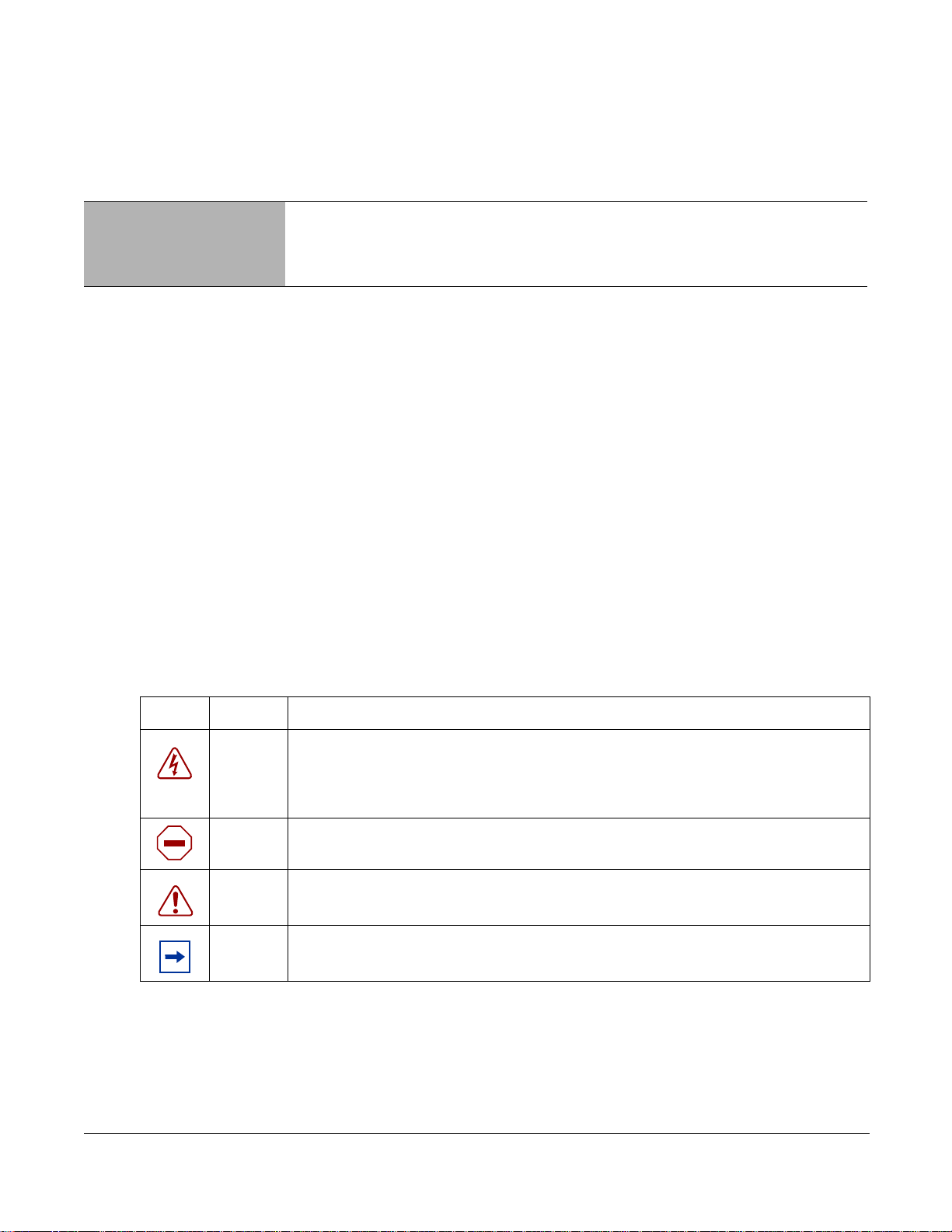
Information Symbols
The following graphic symbols are used in this document to bring attention to hazards that exist when
handling the S50 and its components. Please read these alerts and heed their warnings and cautions.
Table 1 describes symbols contained in this guide.
Table 1 Information Symbols
Symbol Warning Description
This symbol warns that improper handling and installation could result in bodily
Danger
Caution
Warning
Note This symbol informs you of important operational information.
Installing the S50 System 5
injury. Before you begin work on this equipment, be aware of hazards involving
electrical circuitry, networking environments, and instigate accident prevention
procedures.
This symbol informs you that improper handling and installation could result in
equipment damage or loss of data.
This symbol informs you that improper handling may reduce your component or
system performance.

Related Publications
For more information about the S50, refer to the following documents:
• SFTOS™ Configuration Guide
• SFTOS Command Reference
• S50 Quick Reference
• S-Series and SFTOS Release Notes
Each of these documents are available on the product CD-ROM and on the iSupport website (registration
for access to some sections is required):
https://www.force10networks.com/csportal20/KnowledgeBase/Documentation.aspx
The iSupport website also has a section for S-Series techtips and FAQs.
The CD-ROM also has:
• MIBs: Files for all SNMP MIBs supported by SFTOS
• Data sheets: Links to Force10 product data sheets
• Security: Description and supporting files for setting up SSH, SSL, and HTTPS access to the switch
• Software: SFTOS Layer 2 software
• Training: PDF files of the slide shows used in training
6 About this Guide

Chapter 1 The S50 System
A
The Force10 Networks S50 is a high performance, low cost, stackable, Layer 2 switch/Layer 3 router that
supports 48 built-in 10/100/1000 Base-T ports, four SFP (small form-factor pluggable) ports, and two
optional 10-Gigabit XFP or CX4 ports. For stacking details, see Chapter 3, Installing the S50, on page 22.
Stacking
Indicator
LEDs
fn00157s50
Status Panel
OK
PWR
FAN
XFP1
LEDs
Ethernet Ports
PRI
BPS
TMP
XFP2
Shared
10/100/1000
Ports
SFP RJ-45
Ports Management
Port
Figure 1 The S50 (Front View)
Ground Connector
C Power Receptacle
DC Power Module (optional)
Stack
Port A
Stack
Port B
10-Gigabit Module
XFP2
LINK/ACT
fn00158s50
XFP1
LINK/ACT
Figure 2 The S50 (Rear View)
Installing the S50 System 7

Equipment
The following items are necessary to install the S50 system:
• The switch
• One grounded AC power source per S50
• Cable to connect the AC power source to the S50 chassis (included)
• Brackets for rack installation (supplied)
• Screws for rack installation and #2 Phillips screwdriver (not supplied)
Other optional components are:
• Stacking cables for connecting S50s when stacked
• Backup DC Power Module (see Chapter 4, Installing Backup Power, on page 27)
• Power Supply Unit (AC-to-DC converter)
• External power shelf and cable to connect to the S50 chassis
• Optical networking components (see Chapter 5, Installing Ports, on page 31)
Features
• S50 CPU and switch processor
• S50 memory and MAC addresses
• Stackable switch features
• 19-inch rack-mountable
• Standard 1U chassis height
• Six built-in fans
• Internal power supply
• Up to 16K MAC address entries supported with hardware assisted aging
• Supports 9K jumbo frames
• Back-pressure support at half-duplex, IEEE 802.3x flow control at full duplex
• Extensive LED system with per-port LEDs
Ports
• Two optional XFP or CX4 10G ports
• 48 fixed 10/100/1000 Mbps auto-sensing and auto MDIX RJ45 ports
• Four ports capable of using 10/100/1000 Base-T or 1000 Base-X using auto-media detect
• Two 10G stacking ports
• Console port (see Accessing the Console Port on page 31): Supplied with console cable
(straight-through Ethernet copper cable) and terminal adapter (DB-9 to RJ-45)
8 The S50 System

System Status
S50 status information can be derived in several ways, including physical LED displays and boot menu
options, both discussed here, along with CLI “show” commands, SNMP traps, and the SFTOS Web User
Interface. For details on those options, see the SFTOS Command Reference and the SFTOS Configuration
Guide.
LED Displays
As shown in Figure 1 on page 7, the S50 front panel contains several sets of LEDs:
• Stacking LEDs at the top right of the front panel: Eight LEDs, numbered 1 through 8, indicate the
number of this unit in the stack. For more on unit numbering, see Hot-swapping Units in a Stack on
page 24.
• Status indicator LEDs on the left side of the front panel, explained in Table 3.
• Each port has status indicator LEDs, described in Table 2.
Table 2 Port LED Displays
Feature Description
10/100/1000 Port LED
SFP Port LED
XFP Port LED
*
*
Speed LED (left side of each port)
Green — 1000M
Amber — 100M
Off — 10M
Link/Active LED (right side of each port)
Green — Link up on this port
Blinking Green — Activity, transmitting or receiving packet at this port.
Off — No Link detected at this port
Link/Activity LED
Green — Link up on this port
Blinking Green — Activity, transmitting or receiving packet in link up state
Off — No Link detected at this port
Link/Activity LED
Green — Link up on this port
Blinking Green — Activity, transmitting or receiving packet in link up state
Off — No Link detected at this port
* The LEDs for a 10/100/1000 port numbered 45 through 48 are inactive if the shared SFP port (also labeled 45 through
48) is enabled.
Note: As suggested by the footnote above, the fiber SFP ports have priority over the four 10/100/1000
ports with the same number.
Installing the S50 System 9

The following table describes the LED status indicators on the left side of the front panel.
Table 3 Status Panel LED Display
Label LED Color Description
OK
PWR
FAN
XFP1
PRI
BPS
TEMP
Green
Off
Green Blinking
Amber Blinking
Green
Amber
Green
Amber
Green
Blinking Green
Off
Green
OFF
Green
Amber
Green
Amber
Unit is operational.
Unit is powered off.
Unit is booting up.
File download is in progress.
Note: The blinking rate for the OK (green) LED is 1 Hz.
Main power supply is OK.
Main power supply is operating outside expected parameters.
All Fans are OK.
At least one fan is operating outside expected parameters.
10G1 link
10G1 active
10G1 no link
This is the primary unit.
This is not the primary unit.
Redundant power supply is OK.
Redundant power supply is operating outside expected parameters or
is not installed.
Temperature is OK.
Temperature is operating outside expected parameters.
XFP2
10 The S50 System
Green
Blinking Green
Off
10G2 link
10G2 active
10G2 no link

Chapter 2 Site Prep arations
This chapter describes requirements and procedures to install your S50 system. This chapter covers the
following topics:
• Site Selection
• Cabinet Placement
• Rack Mounting
• Fans and Airflow
• Power
• Storing Components
For detailed S50 specifications, refer to Chapter 6, S50 Specifications, on page 35.
Note: Install the S50 into a rack or cabinet before installing any optional components.
Site Selection
Make sure that the area where you install your S50 chassis meets the following safety requirements:
• Near an adequate power source. Connect the system to the appropriate branch circuit protection as
defined by your local electrical codes.
• Environmental temperature between 32° – 122°F (0° – 40°C).
• Relative humidity that does not exceed 95% non-condensing.
• In a dry, clean, well-ventilated and temperature-controlled room, away from heat sources such as hot
air vents or direct sunlight.
• Away from sources of severe electromagnetic noise.
• Positioned in a rack, cabinet, or on a desktop with adequate space in the front, rear, and sides of the
unit for proper ventilation, and access.
Installing the S50 System 11

Cabinet Placement
The cabinet must meet the following criteria:
• Minimum cabinet size and airflow are according to the EIA standard.
• Minimum of 5 inches (12.7 cm) between the side intake and exhaust vents and the cabinet wall.
Rack Mounting
When you prepare your equipment rack, ensure that the rack is earth ground. The equipment rack must be
grounded to the same ground point used by the power service in your area. The ground path must be
permanent.
Fans and Airflow
For proper ventilation, position the S50 chassis in an equipment rack (or cabinet) with a minimum of five
inches (12.7 cm) of clearance around the side intake and exhaust vents. When two S50 systems are
installed side by side, position the two S50 chassis at least 5 inches (12.7 cm) apart to permit proper
airflow . The acceptable ambient temperature ranges are listed in Environmental Parameters on page 35.
As listed in Table 3, “Status Panel LED Display,” on page 10, the front panel of the S50 has both a fan
status LED and a temperature LED. The fan status LED is green when all of the six fans are operating
normally, amber when any are not operating normally. The fan speed increases when the temperature of
either of the two sensors reaches 72 degrees C, and decreases to normal speed when the temperature falls
to 57 degrees C. The switch never intentionally stops managing traffic.
The temperature status LED is also green when the switch is operating within required temperature
parameters. The LED turns amber when either of the two temperature sensors indicates an out-of-range
temperature, and returns to green when the temperature returns to normal. SFTOS logs a temperature
warning message when a temperature of 77 degrees C is reached, and logs another message when the
temperature returns to normal.
Use the
of the SFTOS Command Reference or SFTOS Configuration Guide.
In a stack, each unit has its own temperature monitoring and control. Status logging is identified by unit in
the system log.
Fan replacement is not offered as an option in the field.
show logging buffered command to see the log messages. For details, see the Syslog chapters
12 Site Preparations

Power
Use the power cord shipped with the S50 chassis to connect the chassis to the AC power outlet.
Caution: The power supply cord is used as the main disconnect device; ensure that the
socket-outlet is located/installed near the equipment and is easily accessible.
Storing Components
If you do not install your system and components immediately, Force10 Networks recommends that you
properly store the S50 and all optional components until you are ready to install them.
Warning: Electrostatic discharge (ESD) damage can occur when components are mishandled.
Always wear an ESD-preventive wrist or heel ground strap when handling the S50 and its
accessories. After you remove the original packaging, place the S50 and its components on an
antistatic surface.
Follow these storage guidelines:
• Storage temperature should remain constant ranging from -4° to 158° F (-20°C to 70° C).
• Store on a dry surface or floor, away from direct sunlight, heat, and air conditioning ducts.
• Store in a dust-free environment.
Installing the S50 System 13
 Loading...