

Page 1
IP Router
MENU-DRIVEN USER INTERFACE
USER MANUAL
Part Number: 770-0015-BL
Product Release: 2.97
August 2009
Page 2

Copyright © 2009 Force10 Networks Inc. All rights reserved.
Force10 Networks
®
reserves the right to change, modify, revise this publication without notice.
The hardware and software described herein are furnished under a license or non-disclosure agreement. The
hardware, software, and manual may be used or copied only in accordance with the terms of this agreement.
It is against the law to reproduce, transmit, transcribe, store in a retrieval system, or translate into any medium
- electronic, mechanical, magnetic, optical, chemical, manual, or otherwise - any part of this manual or
software supplied with the product for any purpose other than the purchaser’s personal use without the
express written permission of Force10 Networks Inc.
Trademarks
Adit and Force10 Networks are registered trademarks of Force10 Networks, Inc. Force10 and the Force10
logo are trademarks of Force10 Networks, Inc. or its affiliates in the United States and other countries and are
protected by U.S. and international copyright laws. All other brand and product names are trademarks or
registered trademarks of their respective holders.
Statement of Conditions
In the interest of improving internal design, operational function, and/or reliability, Force10 Networks
reserves the right to make changes to products described in this document without notice. Force10 Networks
does not assume any liability that may occur due to the use or application of the product(s) described herein.
Corporate Contact Information:
Force10 Networks, Inc.
350 Holger Way
San Jose, CA 95134-1362
Phone: +1 (866) 571-2600 or +1 (408) 571-3500
www.Force10Networks.com
Supporting Software Versions:
IP Router Release 2.97
Adit 600 Controller Release 10.1.1
Technical Assistance Center:
E-mail: access-support@Force10Networks.com
Phone: (US) 866-887-4638
Phone (International/Direct): 1-707-665-4355
Page 3

Warranty
Force10 Networks, Inc. warrants to BUYER that Product Hardware will be free from substantial
defect in material and workmanship under normal use in accordance with its Documentation and
given proper installation and maintenance for period of five years from the date of shipment by
Force10 Networks.
Force10 Networks warrants that the Licensed Software, when used as permitted under its License
Terms and in accordance with the instructions and configurations described in the Documentation
(including use on Force10 Networks product or a computer hardware and operating system platform
supported by Force10 Networks), will operate substantially as described in the Documentation for a
period of ninety (90) days after date of shipment of the Licensed Software to BUYER.
This warranty shall not apply to Products or Software that have been either resold or transferred from
BUYER to any other party. Any such transfer voids the above warranty and related licenses. Force10
Networks offers expanded product care beyond what is covered by the warranty through different
support plans. The plans are designed to maximize network availability through advance replacement
for defective equipment. Please contact your Force10 Networks representative for support program
details.
PREFACE
Preface
Warranty Procedure
BUYER must promptly notify Force10 Networks of any defect in the Product or Software and
comply with Force10 Networks' return/repair policy and procedures. Force10 Networks or its agent
will have the right to inspect the Product or workmanship on BUYER's premises. With respect to a
warranty defect in Product hardware reported to Force10 Networks by BUYER during the warranty
period, Force10 Networks, as its sole obligation and BUYER's exclusive remedy for any breach of
warranty, will use commercially reasonable efforts, at its option, to:
a. repair, replace, or service at its factory or on the BUYER's premises the Product, or
component therein, or workmanship found to be defective so that the Product
hardware operates substantially in accordance with Force10 Networks
Documentation; or
b. credit BUYER for the Product in accordance with Force10 Networks' depreciation
policy.
Page 4

Preface
With respect to a warranty defect in the Licensed Software reported to Force10 Networks by BUYER
during the 90-day software warranty period, Force10 Networks, at its own expense and as its sole
obligation and BUYER's exclusive remedy for any breach of the software warranty, will use
commercially reasonable efforts to, at its option,
a. correct any reproducible error in the Licensed Software, or
b. replace the defective Licensed Software, as follows:
Should a Severity 1 or 2 warranty defect with the Software occur during the 90-day
warranty period, Force10 Networks will provide, in its sole determination, either
1. software to resolve the defect to be downloaded into the affected units by the
BUYER or
2. a documented workaround to address the issue.
Severity 1 issues are failures of the Licensed Software to comply with the Force10 Networks
software specifications and that completely or severely affect the Force10 Networks Product and
its traffic or service capacity, or maintenance or monitoring capabilities.
Severity 2 issues are failures of the Licensed Software to comply with the Force10 Networks
software specifications and that result in a major degradation of the Force10 Networks Product
so as to impact its system or service performance, or significant impairments to network operator
control or effectiveness. Should a Severity 3 warranty defect with the Licensed Software occur
during the 90-day warranty period, Force10 Networks will provide assistance to Buyer to
determine if a solution or workaround will be provided in a subsequent software release
following the reported issue.
Severity 3 issues are defined as failures of the Licensed Software to comply with the Force10
Networks software specifications but that do not significantly impair the function or service of
the Force10 Networks Product or the system.
Determination of Severity 1, 2 or 3 shall be made solely by Force10 Networks following receipt
of the reported problem. Refurbished material may be used to repair or replace the Product.
BUYER shall bear the risk of loss for Products or Software returned to Force10 Networks for
repair, replacement, or service, and the same must be shipped pre-paid by BUYER.
Requests for warranty services and troubleshooting must be made to, and will be provided by, the
Force10 Networks Customer Support Center via telephone during the warranty period and during
normal business hours. Normal business hours for Force10 Networks Customer Support Center are
7:00 a.m. to 6:00 p.m. Mountain Standard Time, Monday through Friday, excluding weekends and
standard Force10 Networks recognized holidays.
iv IP Router - Release 2.97
Page 5

Preface
Limitation of Warranty & Limitation of Remedies
Correction of defects by repair, replacement, or service will be at Force10 Networks' option and
constitute Force10 Networks' sole obligation and BUYER's sole and exclusive remedy under the
limited warranty. Any such error correction or replacement provided to BUYER does not extend the
original warranty period for hardware or software, respectively.
Force10 Networks assumes no warranty or other liability with respect to defects in the Product or
Software caused by:
a. modification, repair, storage, installation, operation, or maintenance of the Product or
Software by anyone other than Force10 Networks or its agent, or as authorized and
in accordance with the Force10 Networks Documentation; or
b. the negligent, unlawful or other improper use or storage of the Product or Software,
including its use with incompatible equipment or software; or
c. fire, explosion, power failures, acts of God, or any other cause beyond Force10
Networks' reasonable control; or
d. handling or transportation after title of the Product passes to BUYER.
Other manufacturer's equipment or software purchased by Force10 Networks and resold to BUYER
will be limited to that manufacturer's warranty. Force10 Networks assumes no warranty liability for
other manufacturer's equipment or software furnished by BUYER.
BUYER UNDERSTANDS AND AGREES AS FOLLOWS: Except for the limited warranty set forth
above, the Product, License Software and all services performed by Force10 Networks hereunder are
provided "as is," without representations or warranties of any kind. Force10 Networks does not
warrant that the Product, License Software, any hardware or software, or any update, upgrade, fix or
workaround furnished to BUYER will meet BUYER's requirements, that the operation thereof,
including any maintenance or major releases thereto will be uninterrupted or error-free.
THE WARRANTIES IN THIS AGREEMENT REPLACE ALL OTHER WARRANTIES,
EXPRESSED OR IMPLIED, AND ALL OTHER OBLIGATIONS OR LIABILITIES OF FORCE10
NETWORKS, INCLUDING ANY WARRANTIES OF MERCHANTABILITY, FITNESS FOR A
PARTICULAR PURPOSE, NONINFRINGEMENT AND/OR ANY IMPLIED WARRANTIES
ARISING OUT OF COURSE OF PERFORMANCE OR COURSE OF DEALING. ALL OTHER
WARRANTIES ARE DISCLAIMED AND EXCLUDED BY FORCE10 NETWORKS.
THE REMEDIES CONTAINED IN THIS AGREEMENT WILL BE THE SOLE AND
EXCLUSIVE REMEDIES WHETHER IN CONTRACT, TORT, OR OTHERWISE, AND
FORCE10 NETWORKS WILL NOT BE LIABLE FOR INJURIES OR DAMAGES TO PERSONS
OR PROPERTY RESULTING FROM ANY CAUSE WHATSOEVER, WITH THE EXCEPTION
OF INJURIES OR DAMAGES CAUSED BY THE GROSS NEGLIGENCE OF FORCE10
NETWORKS. THIS LIMITATION APPLIES TO ALL SERVICES, SOFTWARE, AND
PRODUCTS DURING AND AFTER THE WARRANTY PERIOD. IN NO EVENT WILL
FORCE10 NETWORKS BE LIABLE FOR ANY SPECIAL, INCIDENTAL, OR
CONSEQUENTIAL DAMAGES, LOSS OF DATA, OR COMMERCIAL LOSSES EVEN IF
FORCE10 NETWORKS HAS BEEN ADVISED THEREOF.
IP Router - Release 2.97 v
Page 6

Preface
No agent, BUYER, or representative is authorized to make any warranties on behalf of Force10
Networks or to assume for Force10 Networks any other liability in connection with any of Force10
Networks' Products, software, or services.
The foregoing summarizes Force10 Networks' entire product and software warranties, which are
subject to change without notice.
Warranty Product Returns
Before returning any equipment to Force10 Networks, Inc., first contact the distributor or dealer from
which you purchased the product.
A Return Material Authorization (RMA) number is required for all equipment returned to Force10
Networks, Inc. Call Force10 Networks Customer Support at 1-866-887-4638 (US) or 1-707-6654355 (International/Direct) for RMA number, repair/warranty information and shipping instructions.
Be prepared to provide the following information:
Force10 Networks serial number(s) from the system chassis or circuit card(s)
Name of distributor or dealer from which you purchased the product
Description of defect
vi IP Router - Release 2.97
Page 7

Preface
Notices
This manual contains important information and warnings that must be followed to
ensure safe operation of the equipment.
DANGER! A DANGER NOTICE INDICATES THE PRESENCE OF A HAZARD THAT
CAN OR WILL CAUSE DEATH OR SEVERE PERSONAL INJURY IF THE HAZARD IS
NOT AVOIDED.
CAUTION! A CAUTION NOTICE INDICATES THE POSSIBILITY OF
INTERRUPTING NETWORK SERVICE IF THE HAZARD IS NOT AVOIDED.
WARNING! A WARNING NOTICE INDICATES THE POSSIBILITY OF EQUIPMENT
DAMAGE IF THE HAZARD IS NOT AVOIDED.
NOTE: A Note indicates information to help you understand how to
perform a procedure or how the system works. Notes should be read before
performing the required action.
IP Router - Release 2.97 vii
Page 8

Preface
viii IP Router - Release 2.97
Page 9

TABLE OF CONTENTS
Table of Contents
Preface
Warranty . . . . . . . . . . . . . . . . . . . . . . . . . . . . . . . . . . . . . . . . . . . . . . . . . . . iii
Warranty Procedure . . . . . . . . . . . . . . . . . . . . . . . . . . . . . . . . . . . . . . iii
Limitation of Warranty & Limitation of Remedies . . . . . . . . . . . . . . . v
Warranty Product Returns . . . . . . . . . . . . . . . . . . . . . . . . . . . . . . . . . . vi
Notices . . . . . . . . . . . . . . . . . . . . . . . . . . . . . . . . . . . . . . . . . . . . . . . . . . . . vii
1 Introduction
Overview . . . . . . . . . . . . . . . . . . . . . . . . . . . . . . . . . . . . . . . . . . . . . . . . . . 1-2
Installation. . . . . . . . . . . . . . . . . . . . . . . . . . . . . . . . . . . . . . . . . . . . . . . . . 1-2
Install a Router Card . . . . . . . . . . . . . . . . . . . . . . . . . . . . . . . . . . . . . 1-2
Maneuvering in the System. . . . . . . . . . . . . . . . . . . . . . . . . . . . . . . . . . . . 1-2
Fields . . . . . . . . . . . . . . . . . . . . . . . . . . . . . . . . . . . . . . . . . . . . . . . . . . . . . 1-3
Scroll Field. . . . . . . . . . . . . . . . . . . . . . . . . . . . . . . . . . . . . . . . . . . . . 1-3
Select Field. . . . . . . . . . . . . . . . . . . . . . . . . . . . . . . . . . . . . . . . . . . . . 1-3
Edit Field . . . . . . . . . . . . . . . . . . . . . . . . . . . . . . . . . . . . . . . . . . . . . . 1-3
Help Bar . . . . . . . . . . . . . . . . . . . . . . . . . . . . . . . . . . . . . . . . . . . . . . . . . . 1-4
Connecting to the Router. . . . . . . . . . . . . . . . . . . . . . . . . . . . . . . . . . . . . . 1-5
Establish a Telnet Session . . . . . . . . . . . . . . . . . . . . . . . . . . . . . . . . . 1-5
Set a New Password. . . . . . . . . . . . . . . . . . . . . . . . . . . . . . . . . . . . . . 1-6
Page 10

Table of Contents
2 Management Window
Management Overview . . . . . . . . . . . . . . . . . . . . . . . . . . . . . . . . . . . . . . . 2-2
System Time/Login . . . . . . . . . . . . . . . . . . . . . . . . . . . . . . . . . . . . . . . . . .2-3
System Date and Time . . . . . . . . . . . . . . . . . . . . . . . . . . . . . . . . . . . .2-4
Daylight Savings Time Adjustment . . . . . . . . . . . . . . . . . . . . . . . . . .2-5
Auto-Logout Timer . . . . . . . . . . . . . . . . . . . . . . . . . . . . . . . . . . . . . . .2-5
View Password . . . . . . . . . . . . . . . . . . . . . . . . . . . . . . . . . . . . . . . . . .2-5
Config Password . . . . . . . . . . . . . . . . . . . . . . . . . . . . . . . . . . . . . . . . . 2-5
Admin Password . . . . . . . . . . . . . . . . . . . . . . . . . . . . . . . . . . . . . . . . .2-5
Enhanced Security. . . . . . . . . . . . . . . . . . . . . . . . . . . . . . . . . . . . . . . .2-6
Upload/Download. . . . . . . . . . . . . . . . . . . . . . . . . . . . . . . . . . . . . . . . . . . . 2-8
Set up the Router for Uploads/Downloads . . . . . . . . . . . . . . . . . . . . .2-9
Upload/Download Setup Menu Fields . . . . . . . . . . . . . . . . . . . . . . . 2-12
Load Defaults . . . . . . . . . . . . . . . . . . . . . . . . . . . . . . . . . . . . . . . . . . . . . . 2-14
Software Images . . . . . . . . . . . . . . . . . . . . . . . . . . . . . . . . . . . . . . . . . . . . 2-15
Options . . . . . . . . . . . . . . . . . . . . . . . . . . . . . . . . . . . . . . . . . . . . . . .2-16
3 Profile Directory: Router Card Profile
Overview . . . . . . . . . . . . . . . . . . . . . . . . . . . . . . . . . . . . . . . . . . . . . . . . . . 3-2
Configuration . . . . . . . . . . . . . . . . . . . . . . . . . . . . . . . . . . . . . . . . . . . . . . .3-2
RIP Mode Receive . . . . . . . . . . . . . . . . . . . . . . . . . . . . . . . . . . . . . . . . . . . 3-4
RIP Mode Send. . . . . . . . . . . . . . . . . . . . . . . . . . . . . . . . . . . . . . . . . . . . . . 3-4
Trunk . . . . . . . . . . . . . . . . . . . . . . . . . . . . . . . . . . . . . . . . . . . . . . . . . . . . . 3-4
Security. . . . . . . . . . . . . . . . . . . . . . . . . . . . . . . . . . . . . . . . . . . . . . . . . . . .3-7
SNMP . . . . . . . . . . . . . . . . . . . . . . . . . . . . . . . . . . . . . . . . . . . . . . . . . . . . 3-11
DNS Proxy . . . . . . . . . . . . . . . . . . . . . . . . . . . . . . . . . . . . . . . . . . . . . . . . 3-16
Spanning Tree Protocol . . . . . . . . . . . . . . . . . . . . . . . . . . . . . . . . . . . . . .3-18
Network Time Protocol . . . . . . . . . . . . . . . . . . . . . . . . . . . . . . . . . . . . . .3-20
SysLog . . . . . . . . . . . . . . . . . . . . . . . . . . . . . . . . . . . . . . . . . . . . . . . . . . .3-23
DNS Resolver. . . . . . . . . . . . . . . . . . . . . . . . . . . . . . . . . . . . . . . . . . . . . .3-25
iv IP Router - Release 2.97
Page 11

Table of Contents
4 Profile Directory: Local Profile
Overview . . . . . . . . . . . . . . . . . . . . . . . . . . . . . . . . . . . . . . . . . . . . . . . . . . 4-2
LAN (Local) Profile Setup . . . . . . . . . . . . . . . . . . . . . . . . . . . . . . . . . . . . 4-4
To Set Up a Local Profile: . . . . . . . . . . . . . . . . . . . . . . . . . . . . . . . . . 4-5
LAN IP: . . . . . . . . . . . . . . . . . . . . . . . . . . . . . . . . . . . . . . . . . . . . . . . 4-8
LAN IPX:. . . . . . . . . . . . . . . . . . . . . . . . . . . . . . . . . . . . . . . . . . . . . . 4-8
Setup < > . . . . . . . . . . . . . . . . . . . . . . . . . . . . . . . . . . . . . . . . . . . . . . 4-9
Link Speed . . . . . . . . . . . . . . . . . . . . . . . . . . . . . . . . . . . . . . . . . . . . 4-10
Static Networks . . . . . . . . . . . . . . . . . . . . . . . . . . . . . . . . . . . . . . . . . . . . 4-11
To Set Up Static Networks. . . . . . . . . . . . . . . . . . . . . . . . . . . . . . . . 4-13
Static Addresses . . . . . . . . . . . . . . . . . . . . . . . . . . . . . . . . . . . . . . . . . . . 4-18
Filters. . . . . . . . . . . . . . . . . . . . . . . . . . . . . . . . . . . . . . . . . . . . . . . . . . . . 4-22
Defining Custom Filters. . . . . . . . . . . . . . . . . . . . . . . . . . . . . . . . . . 4-25
Defining Protocol Filters . . . . . . . . . . . . . . . . . . . . . . . . . . . . . . . . . 4-27
Defining Address Filters . . . . . . . . . . . . . . . . . . . . . . . . . . . . . . . . . 4-29
Firewall Filters (Local Profile) . . . . . . . . . . . . . . . . . . . . . . . . . . . . . . . . 4-31
Advertise Network/Server. . . . . . . . . . . . . . . . . . . . . . . . . . . . . . . . . . . . 4-39
IPX Server Advertising . . . . . . . . . . . . . . . . . . . . . . . . . . . . . . . . . . 4-43
DHCP Server/Client/Relay . . . . . . . . . . . . . . . . . . . . . . . . . . . . . . . . . . . 4-45
LAN Collision Threshold . . . . . . . . . . . . . . . . . . . . . . . . . . . . . . . . . . . . 4-53
Spanning Tree . . . . . . . . . . . . . . . . . . . . . . . . . . . . . . . . . . . . . . . . . . . . . 4-56
Secondary IP Address . . . . . . . . . . . . . . . . . . . . . . . . . . . . . . . . . . . . . . . 4-59
Link Speed. . . . . . . . . . . . . . . . . . . . . . . . . . . . . . . . . . . . . . . . . . . . . . . . 4-62
5 Profile Directory:Remote Profile
Remote (WAN) Profile Overview. . . . . . . . . . . . . . . . . . . . . . . . . . . . . . . 5-2
Transmission Options . . . . . . . . . . . . . . . . . . . . . . . . . . . . . . . . . . . . 5-6
Security/Options . . . . . . . . . . . . . . . . . . . . . . . . . . . . . . . . . . . . . . . . . . . 5-16
Static/VPN Networks . . . . . . . . . . . . . . . . . . . . . . . . . . . . . . . . . . . . . . . 5-19
GRE Tunnel set to <All> . . . . . . . . . . . . . . . . . . . . . . . . . . . . . . . . . 5-21
GRE Tunnel set to <By Network>. . . . . . . . . . . . . . . . . . . . . . . . . . 5-23
Static NAT Addresses . . . . . . . . . . . . . . . . . . . . . . . . . . . . . . . . . . . . . . . 5-27
NAT Bypass Subnets . . . . . . . . . . . . . . . . . . . . . . . . . . . . . . . . . . . . . . . 5-30
Static Addresses . . . . . . . . . . . . . . . . . . . . . . . . . . . . . . . . . . . . . . . . . . . 5-32
IP Router - Release 2.97 v
Page 12

Table of Contents
6 Basic Configuration
Firewall Filters (Remote Profile) . . . . . . . . . . . . . . . . . . . . . . . . . . . . . . . 5-36
Filter Network/Server. . . . . . . . . . . . . . . . . . . . . . . . . . . . . . . . . . . . . . . .5-43
Spanning Tree. . . . . . . . . . . . . . . . . . . . . . . . . . . . . . . . . . . . . . . . . . . . . .5-48
Trunk Port. . . . . . . . . . . . . . . . . . . . . . . . . . . . . . . . . . . . . . . . . . . . . . . . .5-51
Overview . . . . . . . . . . . . . . . . . . . . . . . . . . . . . . . . . . . . . . . . . . . . . . . . . . 6-2
Start Basic Configuration . . . . . . . . . . . . . . . . . . . . . . . . . . . . . . . . . . . . . .6-2
Local Unit Identification . . . . . . . . . . . . . . . . . . . . . . . . . . . . . . . . . . . . . .6-4
Routing Protocol/Security . . . . . . . . . . . . . . . . . . . . . . . . . . . . . . . . . . . . . 6-5
WAN Interface Connections . . . . . . . . . . . . . . . . . . . . . . . . . . . . . . . . . . .6-7
Remote Unit Profile . . . . . . . . . . . . . . . . . . . . . . . . . . . . . . . . . . . . . . . . . . 6-9
SNMP Configuration . . . . . . . . . . . . . . . . . . . . . . . . . . . . . . . . . . . . . . . .6-12
Setup Complete . . . . . . . . . . . . . . . . . . . . . . . . . . . . . . . . . . . . . . . . . . . .6-13
7 Verification Window
Ping Utility . . . . . . . . . . . . . . . . . . . . . . . . . . . . . . . . . . . . . . . . . . . . . . . . .7-2
Trace Route . . . . . . . . . . . . . . . . . . . . . . . . . . . . . . . . . . . . . . . . . . . . . . . . 7-6
Port Monitor . . . . . . . . . . . . . . . . . . . . . . . . . . . . . . . . . . . . . . . . . . . . . . . .7-9
8 Statistics Window
Run-Time . . . . . . . . . . . . . . . . . . . . . . . . . . . . . . . . . . . . . . . . . . . . . . . . . . 8-2
9 System Reports Window
Events . . . . . . . . . . . . . . . . . . . . . . . . . . . . . . . . . . . . . . . . . . . . . . . . . . . . . 9-2
Alarms . . . . . . . . . . . . . . . . . . . . . . . . . . . . . . . . . . . . . . . . . . . . . . . . . . . .9-4
Networks/Servers . . . . . . . . . . . . . . . . . . . . . . . . . . . . . . . . . . . . . . . . . . . .9-6
Address Tables . . . . . . . . . . . . . . . . . . . . . . . . . . . . . . . . . . . . . . . . . . . . . 9-11
10 Exit Window
Logout . . . . . . . . . . . . . . . . . . . . . . . . . . . . . . . . . . . . . . . . . . . . . . . . . . .10-2
Reinitialize . . . . . . . . . . . . . . . . . . . . . . . . . . . . . . . . . . . . . . . . . . . . . . . . 10-3
vi IP Router - Release 2.97
Page 13

Table of Contents
11 Router Configuration
Basic Setup . . . . . . . . . . . . . . . . . . . . . . . . . . . . . . . . . . . . . . . . . . . . . . . 11-2
PPP Internet Connection and
Public IP Address Routing. . . . . . . . . . . . . . . . . . . . . . . . . . . . . . . . 11-3
Frame Relay Internet Connection and
Public IP Address Routing. . . . . . . . . . . . . . . . . . . . . . . . . . . . . . . . 11-4
Internet Connection using PPP, NAT/PAT and Firewall Filters . . . . . . 11-5
Internet Connection using NAT and Static NAT Addresses. . . . . . . . . . 11-7
Back-to-Back with PPP. . . . . . . . . . . . . . . . . . . . . . . . . . . . . . . . . . . . . . 11-9
Back-to-Back with Multi-Link PPP . . . . . . . . . . . . . . . . . . . . . . . . . . . 11-11
Boulder Router in Slot 1 . . . . . . . . . . . . . . . . . . . . . . . . . . . . . . . . 11-11
Denver Router in Slot 1 . . . . . . . . . . . . . . . . . . . . . . . . . . . . . . . . . 11-12
Back-to-Back with Frame Relay . . . . . . . . . . . . . . . . . . . . . . . . . . . . . . 11-13
A User Events
User Events . . . . . . . . . . . . . . . . . . . . . . . . . . . . . . . . . . . . . . . . . . . . . . . . A-2
Authenticate Events. . . . . . . . . . . . . . . . . . . . . . . . . . . . . . . . . . . . . . . . . . A-3
Triggered Events . . . . . . . . . . . . . . . . . . . . . . . . . . . . . . . . . . . . . . . . . . . . A-4
Alarms . . . . . . . . . . . . . . . . . . . . . . . . . . . . . . . . . . . . . . . . . . . . . . . . . . . . A-5
B Protocol Types
Protocol Number in Firewall Filters . . . . . . . . . . . . . . . . . . . . . . . . . . . . . B-2
Ethernet Protocol Types . . . . . . . . . . . . . . . . . . . . . . . . . . . . . . . . . . . . . . B-7
C Troubleshooting
Communication Related Issues . . . . . . . . . . . . . . . . . . . . . . . . . . . . . . . . . C-2
Excessive Triggered Update Events on the Events screen . . . . . . . . C-2
LAN Related Issues. . . . . . . . . . . . . . . . . . . . . . . . . . . . . . . . . . . . . . . . . . C-2
Unable to add data filters, advertise networks or create static
route entries . . . . . . . . . . . . . . . . . . . . . . . . . . . . . . . . . . . . . . . . . . . . C-2
Unable to access the Local (LAN) Router unit via Telnet. . . . . . . . . C-4
Unable to access a remote unit via Telnet . . . . . . . . . . . . . . . . . . . . . C-4
IP Router - Release 2.97 vii
Page 14

Table of Contents
Diagnostics and Performance Tools. . . . . . . . . . . . . . . . . . . . . . . . . . . . . C-5
Verification . . . . . . . . . . . . . . . . . . . . . . . . . . . . . . . . . . . . . . . . . . . . C-6
Statistics . . . . . . . . . . . . . . . . . . . . . . . . . . . . . . . . . . . . . . . . . . . . . . C-6
System Reports . . . . . . . . . . . . . . . . . . . . . . . . . . . . . . . . . . . . . . . . . C-7
Alarms . . . . . . . . . . . . . . . . . . . . . . . . . . . . . . . . . . . . . . . . . . . . . . . . . . . C-8
Identify Alarm . . . . . . . . . . . . . . . . . . . . . . . . . . . . . . . . . . . . . . . . . . C-8
Clear Alarm . . . . . . . . . . . . . . . . . . . . . . . . . . . . . . . . . . . . . . . . . . . C-10
Glossary
Index
viii IP Router - Release 2.97
Page 15

CHAPTER
In this Chapter
Overview
Installation
Maneuvering in the System
1
Introduction
Fields
Help Bar
Connecting to the Router
Page 16

Introduction
Overview
Overview
The IP Router can be configured using CLI via telnet or through the Router
Menu-driven Software.
This manual covers the Router menu-driven user interface only. All other information
for the Router can be found in the Adit 600 User Manual.
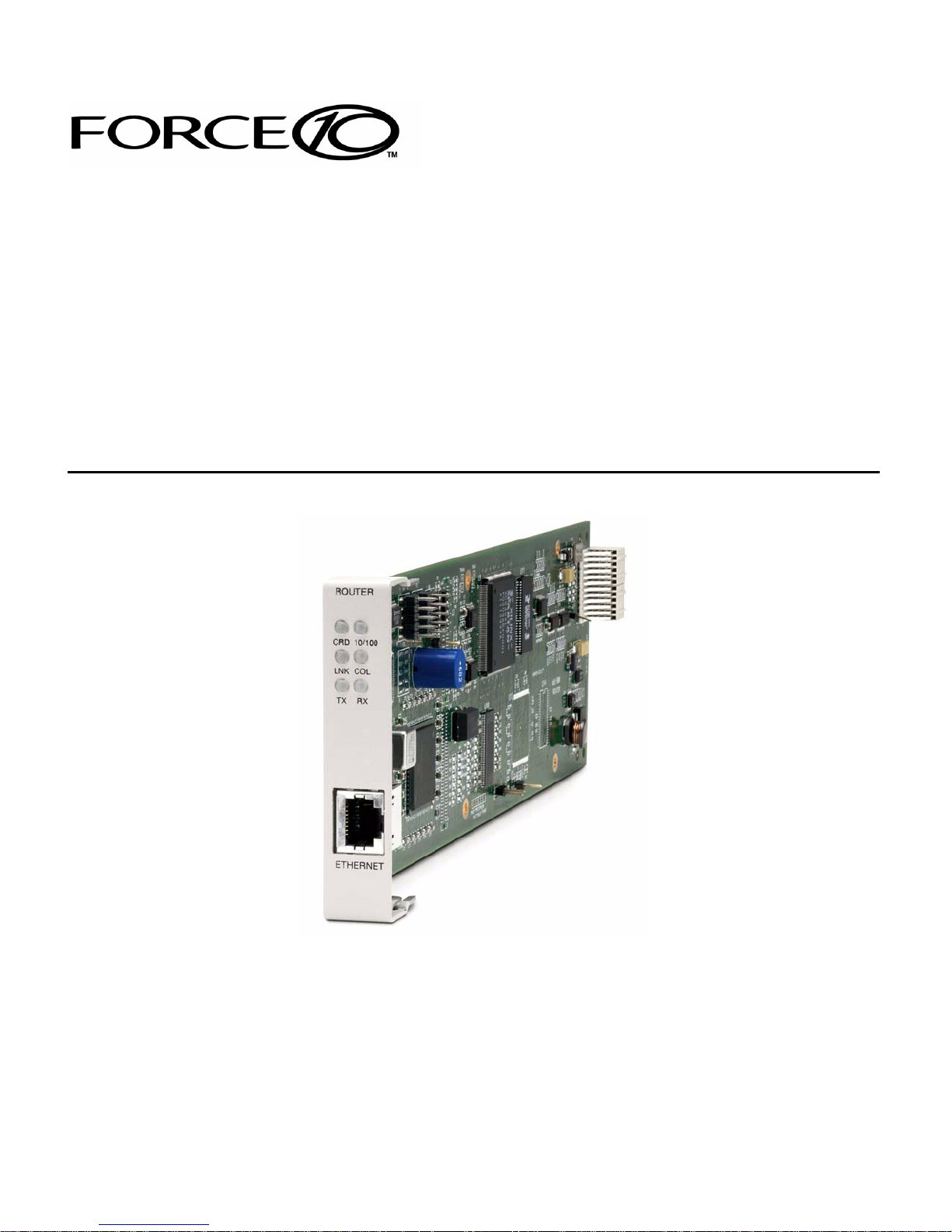
Installation
The IP Router card can be installed into any of the service card slots (1-6) of the Adit
600 chassis. This card is hot-swappable, therefore the card can be removed and
replaced without bringing down the system or with or without power to the unit.
Install a Router Card
1. Slide the Router card into a service card slot of the chassis.
2. Press firmly into slot to engage, until card is seated completely.
3. Card has completed bootup when a solid Red CRD light (an LED) is displayed.
Maneuvering in the System
[TAB] moves from one field to the next.
Keyboard arrows move to the next field in the direction of the arrow.
[ ] Items in brackets are scrollable options. With the Spacebar the operator can move
through the selections.
[E
NTER] displays the window for the selected feature or to enter a alphanumeric value.
[E
SC] Exit and return to previous window or to the Main Menu.
Help Bar - is displayed along the bottom of the window and lists options for the
selected feature.
The Router software contains three different field types that may be used in entering
information: scroll, select and edit.
1-2 IP Router - Release 2.97
Page 17

Introduction
Fields
Fields
Scroll Field
A field enclosed in angle brackets is a scrollable option field. While the field is
selected use the following keystrokes:
PACEBAR] will scroll forward through the options
[S
[E
NTER] will open the option’s window or accept the entered value.
Example: Terminal: <generic>
Select Field
A field followed by –> is a selectable field, which causes an action to be performed,
highlight the field and press [E
NTER] to perform the action, for example, to enter
the Trunk Port Setup screen.
Example: SETUP <Trunk> –>
Some selectable fields, such as Main Menu options, are also a scrollable option
field. For example, <Events>–>. Press the [S
and then press [E
NTER] to perform the action.
PACEBAR] to select the desired option
Edit Field
A field value enclosed in parentheses ( ) may be modified by entering an
alphanumeric character.
Example: SYSTEM NAME: (Adit 600)
You will note that many editable fields are displayed with a default value. To
change this value, highlight the field and type over the existing entry or press
[D
ELETE] and then enter new value. Note: these fields are case sensitive. To enter
this value press [E
NTER].
IP Router - Release 2.97 1-3
Page 18
Introduction
Help Bar
Help Bar
The IP Router provides field specific help that is displayed at the bottom of the window.
The help text will indicate if the field is scrollable or editable and provide a brief
description of the field. If it is a selectable field, it will state what to do to invoke the
action to be performed.
1-4 IP Router - Release 2.97
Page 19

Introduction
Connecting to the Router
Connecting to the Router
Establish a Telnet Session
1. Use the telnet {rtr_card-addr} CLI command to connect to the Router
card. The following example is when the router is located in slot 6.
> telnet 6
Connected.
Escape character is '^]'.
Attempting Force10 Networks Router connection...
Router [Sat Apr 10, 2004 10:51:23] (<CR> to login)
2. Select [ENTER] or <CR> to log in.
Password >
3. Enter default password (admin) and press [ENTER].
Password >*****
Select a terminal type...
(<space> or <back-space> to toggle, <CR> to accept)
Terminal: <VT100>
4. Select Terminal Type: scroll through options with the [SPACEBAR] and then
NTER] to select. Recommended <generic>.
[E
Terminal: <generic>
IP Router - Release 2.97 1-5
Page 20

Introduction
Connecting to the Router
Set a New Password
If you have logged in with a default password, for security reasons the password should
be changed, the system directs the user to do so.
> telnet 3
Connected.
Escape character is '^]'.
Attempting Force10 Networks Router connection...
Router [Wed Apr 10, 2004 5:51:21] (<CR> to login)
Password >*****
Select a terminal type...
(<space> or <back-space> to toggle, <CR> to accept)
Terminal: <generic>
You have logged in with a default password.
For security reasons the password should be changed.
Complete the change request and record your new password
for future use.
Password Change Request
(Valid Router passwords are from 5 to 15 alpha-numeric
characters)
NEW Password >******
RETYPE Password >******
After a successful login, the system prompts the user to change the password from the
default.
1. Type in New Password, and press [E
2. Retype in New Password, and press [E
1-6 IP Router - Release 2.97
NTER]
NTER]
Page 21

CHAPTER
Management Window
In this Chapter
Management Overview
System Time/Login
Upload/Download
2
Load Defaults
Software Images
Page 22

Management Window
Management Overview
Management Overview
The Management Menu contains the system components of the IP Router software.
This section is used to define security parameters, factory default settings, as well as
providing software loading and configuration settings for the Router
Management Menu options allow the user to:
Establish the system security features
Install and backup system software
Backup and install configuration settings
Default system parameters to factory settings
NOTE: Two simultaneous sessions are allowed to access the Router
software. For example, one local and one remote (one must be accessing
with the VIEW level).
2-2 IP Router - Release 2.97
Page 23

Management Window
System Time/Login
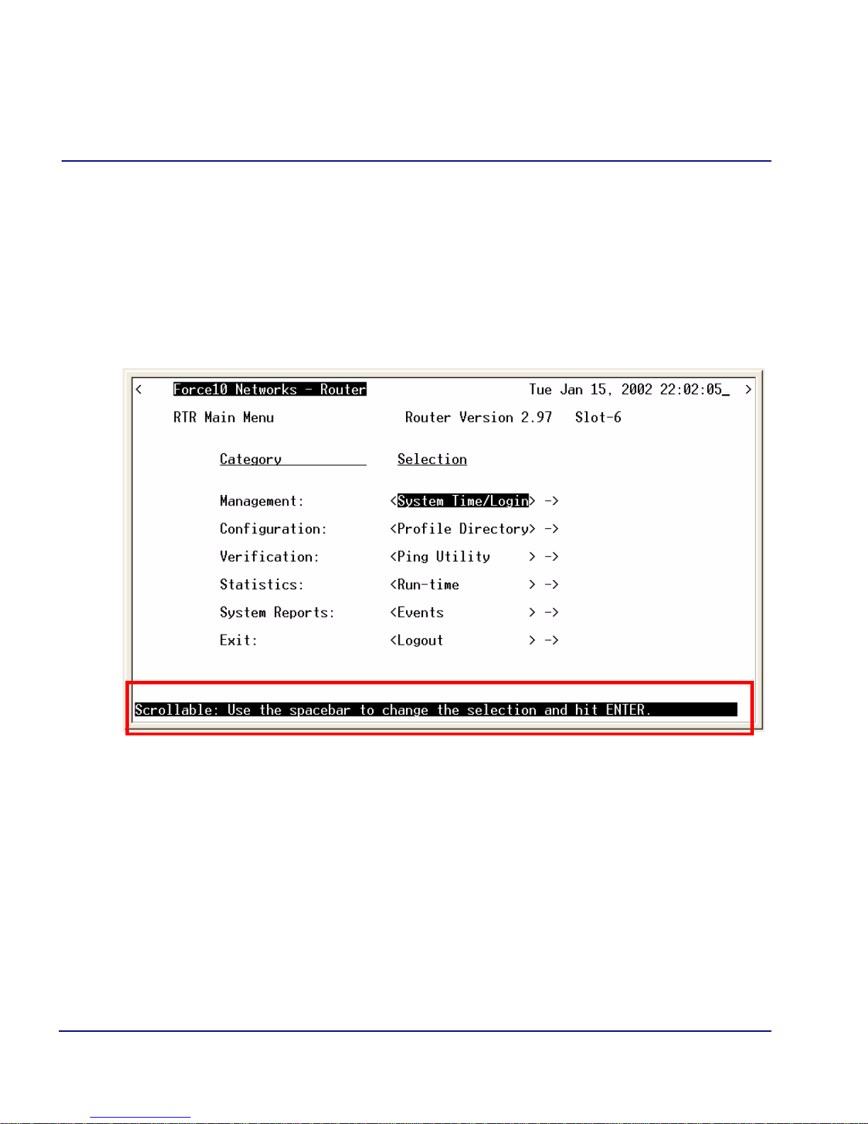
System Time/Login
1. Select Management <System Time/Login> from the Main Menu, and select
NTER].
[E
IP Router - Release 2.97 2-3
Page 24
Management Window
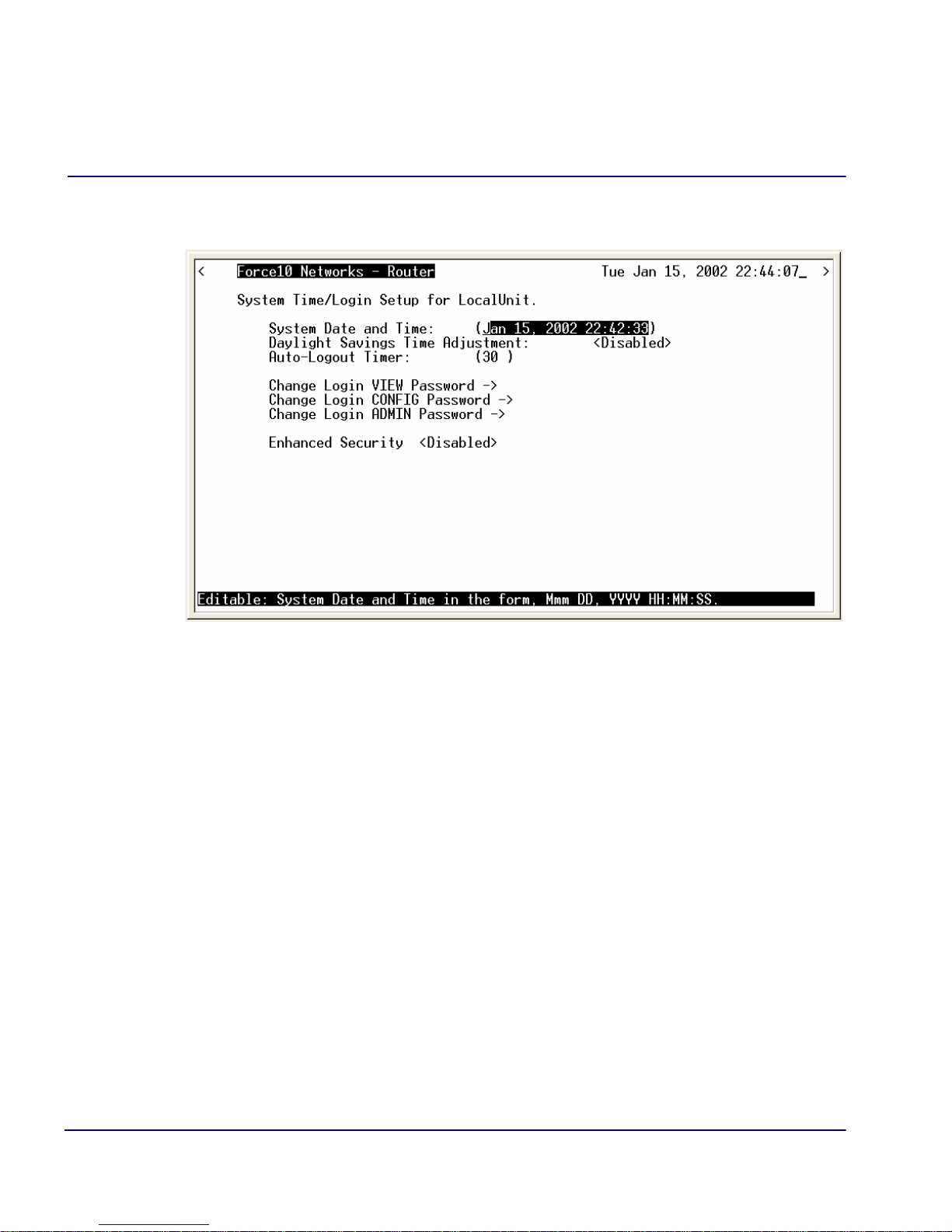
System Time/Login
This screen provides the basic system and security options for the Router card.
The IP Router is equipped with three password levels and an enhanced security
password.
Level 1 VIEW allows the user to view only, no changes are allowed.
Level 2 CONFIG allows the user to view and change all screens.
Level 3 ADMIN allows the user to view and change all screens, terminate
users, as well as change all three passwords.
The Enhanced Security option provides an additional level of security for the
network administrator.
System Date and Time
The time and date values are used for reporting purposes. Enter the date in the
following format: Mmm DD, YYYY. Immediately follow the date with the desired
time entry. The appropriate time format is HH:MM:SS (hour:minute:second).
Press [T
AB] to proceed to the next field.
2-4 IP Router - Release 2.97
Page 25

Management Window
System Time/Login
Daylight Savings Time Adjustment
Use this field to enable or disable automatic adjustment of the system clock for
Daylight Savings Time.
Auto-Logout Timer
This field defines the minutes of inactivity before the current session is terminated.
The default time is 30 minutes. Type the desired auto-logout time (between 1-255).
NOTE: Any changes that have not been saved will be lost when the timer
is activated.
View Password
Users assigned to this level may view only, no changes are allowed. The default
VIEW password is "public". This field must be unique from the CONFIG and
ADMIN passwords. The field may be a 5-15 characters alphanumeric value.
Config Password
Users assigned to this level may view and change all screens. The default
CONFIG password is "config". This entry must be unique from the VIEW and
ADMIN passwords. The field may be a 5-15 character alphanumeric value.
Admin Password
Users assigned to this level may view and change all screens, as well as change all
three password levels. The default ADMIN password is "admin". This entry must
be unique from the VIEW and CONFIG passwords. The field value may be a
5-15 character alphanumeric value.
NOTE: If the default login passwords are not changed, the user will be
prompted, at each login, to enter new passwords at the CONFIG and
ADMIN levels.
IP Router - Release 2.97 2-5
Page 26
Management Window
System Time/Login
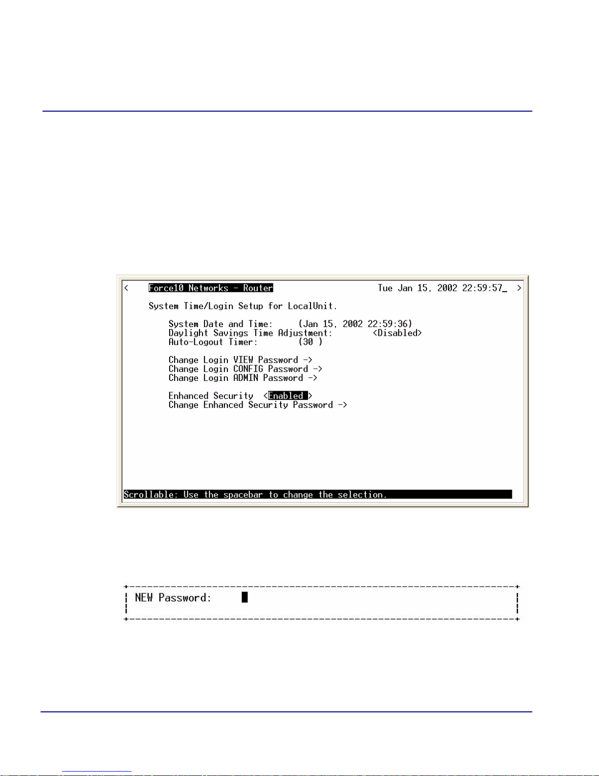
Enhanced Security
The Enhanced Security option provides another level of password security that
restricts access to the Main Menu via Telnet or the Async port. It can be used by a
Network Administrator to only allow those with the Enhanced Security password
to make configuration changes. When enabled, this option hides the system login
prompt until the appropriate password is entered.
1. Use the [S
PACEBAR] to select Enable and [TAB] to enter this selection.
2. The Change Enhanced Security Password - > field will display. Select
NTER] to change password. You will be requested to enter the password
[E
twice to confirm.
2-6 IP Router - Release 2.97
Page 27

Management Window
System Time/Login
When Telneting into the Router with Enhanced Security enabled, the
following will appear:
> telnet 6
Connected.
Escape character is '^]'.
1. Type the Enhanced Security Password here.
NOTE: There will be no effect to the screen here until the correct password
is typed in. When the correct password is typed, no return or other
keystroke is needed, the following will appear:
Password >
WARNING! IF ENHANCED SECURITY IS ENABLED, AND THE ADMINISTRATOR
DOES NOT NOTE THE PASSWORD THERE IS NO WAY TO ACCESS THE ROUTER
UNTIL YOU HAVE RESET THE ROUTER BACK TO IT’S DEFAULT SETTINGS, LOSING
ALL CONFIGURATION SETTINGS. SEE set [rtr_card-addr} default.
2. At this point the Router is requesting your Level 1, 2 or 3 User Password. Enter
your password and select [E
NTER] and continue as you would Telnet into the
Router normally.
Password >******
Select a terminal type...
(<space> or <back-space> to toggle, <CR> to accept)
Terminal: <generic>
IP Router - Release 2.97 2-7
Page 28

Management Window
Upload/Download
Upload/Download
WARNING! BEFORE LOADING A DOWN-LEVEL OF ROUTER CODE, SAVE THE
CONFIGURATION TO A FILE. CONFIGURATION MAY BE RESET TO THE DEFAULT
SETTING AND CURRENT CONFIGURATION LOST.
This window allows the network administrator management of devices and users
authorized to perform:
Installation of software
Backup of software and configuration settings (via tftp)
The IP Router management enables a network administrator to perform a Router Code
Upload from a central location via the LAN or WAN connection using TFTP. A Code
Download can also be performed as a backup (binary image) of the software. Config
Upload and Config Download can be performed remotely via TFTP to install and
backup the IP Router’s configuration to and from a binary file.
There is an additional option to upload code to the IP Router, with the CLI command
load {slot-number} tftp {ip-addr}{"file-name"}
2-8 IP Router - Release 2.97
Page 29
Management Window
Upload/Download
Set up the Router for Uploads/Downloads
1. Select Management: <Upload/Download> from the Main Menu, and
NTER].
[E
IP Router - Release 2.97 2-9
Page 30
Management Window
Upload/Download
2. Select [CTRL A] to add a TFTP Upload/Download User.
NOTE: The IP Address 1. (* ) will display. The * denotes any IP Address on
the defined Client Site. The user may define a specific IP Address for Uploads/
Downloads, by replacing the *, or by Adding another Upload/Download User.
3. Select the Client Site
Selections are: <Local LAN> (default) or RemoteUnits that have been set up.
2-10 IP Router - Release 2.97
Page 31

Management Window
Upload/Download
4. For Mode, specify whether the IP Address can perform code uploads/
downloads, config file uploads/downloads, or both.
5. Press [E
SC] to save your changes and return to the Main Menu. These changes
will go into effect immediately.
IP Router - Release 2.97 2-11
Page 32

Management Window
Upload/Download
Upload/Download Setup Menu Fields
Feature and Release Key Options
Options may be available to purchase, to upgrade the IP Router. Once this option
is purchased, a key code will be given to enable the feature on this product. For
more information please call Force10 Networks’ Technical Assistance Center.
Reboot After Load Code
Use this option to automatically reboot the IP Router after software is successfully
installed. A software load verification verifies that the new software is good before
the unit will accept it. If it is determined to be bad or damaged, the IP Router will
reject it and continue to use the original software.
Reboot After Load Config
Use this option to automatically reboot the IP Router after a configuration file is
successfully installed.
IP Address
The IP Address field is use to identify which device(s) will be allowed to perform
config and/or code uploads and downloads. A “*” in this field will allow all devices
at the selected Client Site to perform Uploads/Downloads.
Client Site
This field identifies the profile the Router will use to reach the IP Address entered
in the previous field. If <Local LAN> is selected, it indicates the device can be
reached via the LAN. If the device can be reached via a WAN connection, you
should select one of the Remote (WAN) profiles.
Mode
Use this field option to enable uploads/downloads of software and configuration
files for specific IP addresses.
Code – Authorizes the IP Address to perform software uploads and downloads.
When new software is installed on the Router, a software load verification checks
and verifies that the new software is good before the unit will accept it. If it is
2-12 IP Router - Release 2.97
Page 33

Management Window
Upload/Download
determined to be bad or damaged, the Router will reject it and continue to use the
original software. Acceptable binary file extensions are .mgm or .MGM.
Config – Authorizes the IP Address to perform configuration file uploads and
downloads. For uploads, this selection allows the device(s) in the IP Address field
to transfer or restore a previously backed-up configuration file to the Router via
TFTP. For downloads, this selection defines an IP Address to which a backup copy
of the Router’s configuration can be sent. Acceptable file extensions are “.cfg” or
“.CFG”.
Both – Authorizes the IP Address to perform code and config file uploads/
downloads.
NOTE: Code and Config uploads will require a reboot of the unit before the
changes take effect.
IP Router - Release 2.97 2-13
Page 34

Management Window
Load Defaults
Load Defaults
Use the Load Defaults option to reset the Router software to the factory defaults. This
option will delete all configuration settings, including the passwords.
Use the [S
PACEBAR] to choose <Yes> and press [ENTER]. If you have a Telnet
connection to the unit, your session will be terminated.
1. Select Management <Load Defaults> from the Main Menu, and select
[E
NTER].
2. A dialog box will display confirming that you want to load factory defaults.
3. Select <YES> with the [S
4. Defaults will be loaded.
2-14 IP Router - Release 2.97
PACEBAR] and select [ENTER].
Page 35

Management Window
Software Images
Software Images
Use the Software Images option to switch the active with the backup application
images stored in the Router.
1. Select Management <Software Images> from the Main Menu, and select
[Enter].
IP Router - Release 2.97 2-15
Page 36

Management Window
Software Images
Options
Show Current Images - will display the application images stored in the Router
(shown above).
Switch Appl. Images - Switch the active with the backup application images stored in
the router. Note: More than one software image must be loaded (7.0 or later) for an
active and a backup image to display.
2-16 IP Router - Release 2.97
Page 37

CHAPTER
Profile Directory:
Router Card Profile
In this Chapter
Overview
Configuration
RIP Mode Receive
3
RIP Mode Send
Trunk
Security
SNMP
DNS Proxy
Spanning Tree Protocol
Network Time Protocol
SysLog
DNS Resolver
Page 38

Profile Directory: Router Card Profile
Main Menu
Overview
Overview
The Router Card Profile of the Profile Directory is used to review/configure base router
features.
Configuration
1. Select Configuration: <Profile Directory> from the Main Menu, and select
[E
NTER].
3-2 IP Router - Release 2.97
Page 39

Profile Directory: Router Card Profile
Profile
Directory
Window
Router
Card
Configuration
Window
Configuration
2. Select Router CARD <Setup -> and select [ENTER].
IP Router - Release 2.97 3-3
Page 40

Profile Directory: Router Card Profile
RIP Mode Receive
RIP Mode Receive
Selection is: <RIP1>, <RIP2>, or <RIP1/RIP2>.
RIP Mode Send
Selection is: <RIP1>, <RIP2>, or <RIP1/RIP2>.
Trunk
This window is used to configure the Trunk setup for the Router. Although the Router
is designed to connect remote sites over dedicated connections, the unit supports a
number of different encapsulation protocols simultaneously, including Frame Relay
and PPP. The Router provides the flexibility to allow the user to define which slots will
be used for the selected WAN protocol.
1. Select Trunk < Configure -> and select [E
NTER].
3-4 IP Router - Release 2.97
Page 41

Profile Directory: Router Card Profile
Trunk
2. All WAN connections will display in this window. To select the WAN
Connection Type, [T
PACEBAR] to select the Type (PPP, MLPPP, PPP in Frame Relay or Frame
[S
Relay 1490) and select [E
following field definitions.
AB] to the Type on the specific WAN Link #, use the
NTER]. For more information on this window, see the
Trunk Setup Menu Fields
WAN Link #
This field displays the WAN Link Number (1-24) for the WAN Connection.
WAN Connection
The WAN Connection displays the current connection of this WAN, in the form
{slot:port:channel}.
IP Router - Release 2.97 3-5
Page 42

Profile Directory: Router Card Profile
Trunk
WAN Connection Type
Determines the type of protocol encapsulation that will be used for the selected WAN.
PPP
Point-to-Point Protocol. Provides a standard means of encapsulating data packets sent over a single-
channel WAN link. PPP is the standard WAN encapsulation protocol for the inter- operability of
bridges and routers.
MLPPP
MultiLink PPP. When PPP is selected and a Multilink group is chosen the WAN
Connection Type will display MLPPP.
PPP in Frame Relay
Point-to-Point Protocol encapsulated in Frame Relay.
Frame Relay 1490
A packet-switching protocol for connecting devices on a WAN. Frame Relay networks in the U.S.
support data transfer rates at T1 (1.544 Mbps) and T3 (45 Mbps) speeds. Frame Relay service is
provided for customers who want connections at 56 Kbps to T1 speeds.
Multilink Group
Specifies a trunk as part of a multilink PPP group. Selection is: <None> or <1> through
<24>. Available only when PPP connection type is selected.
Data Speed
The Data Speed will specify the data speed for each DS0 in the given trunk.
Selection is: <56K> or <64K>. The default is 64K.
PVC Management
Field Description
Disabled Disables PVC Management
Annex D Frame Relay standard
Poll Interval Range is between 5-30
Poll Counter Range is between 1-255
LMI Local Management Interface
Poll Interval Range is between 5-30
Poll Counter Range is between 1-255
3-6 IP Router - Release 2.97
Page 43

Profile Directory: Router Card Profile
Security
Security
1. Select Security < Configure -> and select [ENTER].
IP Router - Release 2.97 3-7
Page 44

Profile Directory: Router Card Profile
Security
Setup
Window
Security
The fields on this screen may be used to define the authentication process for the Local
Unit.
3-8 IP Router - Release 2.97
Page 45

Profile Directory: Router Card Profile
Security
Security Setup Menu Fields
Authentication by Remote
Protocol: CHAP, PAP or NONE
Use this first field to identify the authentication protocol to be used by remote units when
authenticating this unit.
<CHAP> Challenge Handshake Authentication Protocol
<CHAP> Secret
[ENTER] and a NEW Password dialog box will display. Enter a 1 - 15 character
Select
password and select [ENTER] and a RETYPE Password dialog box will display. Retype
password and select
[ENTER]. Password is now set.
<PAP> Password Authentication Protocol
<PAP> Password
Same as above <CHAP> Secret.
<NONE > No authentication protocol. <NONE> is the default.
User ID
Use this field to define the local unit’s User ID. During the authentication process, the local unit will
send a name or User ID, along with the authentication protocol’s secret or password (see above). Use
the [SPACEBAR] to scroll between <Local Profile Name> (the default value) and <Local Custom
Name>. If set at <Local Profile Name>, the local unit will send the 11 character unit name which
was defined on the Local (LAN) Profile screen. If this field is set to <Local Custom Name> you may
define a 32 character maximum alphanumeric value to represent the User ID which is sent during the
authentication process. Defining a custom User ID simply gives the end user more flexibility for this
value.
To assign a custom User ID, set the USER ID field to <Local Custom Name> and press [
to ten (10) custom names may be configured.
IP Router - Release 2.97 3-9
TAB]. Up
Page 46

Profile Directory: Router Card Profile
Security
Authentication of Remote
Protocol: CHAP, PAP or NONE
Use this field to identify the authentication protocol to be used by this IP Router when authenticating
remote devices.
Local Security Server
Use these fields to identify the local server that is used to authenticate remote devices. This field
is only necessary if you are using either the <RADIUS> or <TACACS+> security
authentication method. If you are not using either of these security methods, the unit will
respond to the authentication requests of remote devices and will accept or reject them based on
their validity.
Type
Use the [SPACEBAR] to choose the security authentication method that you are using.
<None> Use this setting if the Local unit will be used to authenticate remote devices. Please note
that you may not use the <None> setting if the Security Server field for a remote device has been set
to <External Server>
<RADIUS>
Will set the server to use the RADIUS (Remote Authentication Dial-In Service)
protocol. RADIUS is a client/server-based authentication software system.
<TACACS+> Will set the server to use the TACACS+ (Terminal Access Controller Access
Control System) protocol. TACACS+ provides services of authentication, authorization
and accounting independently.
Address
Enter the IP Address of the local server that will be used during the authentication process. If <None>
was selected in the <Type> field, this field will be disabled.
Password
Enter the password of the local server that will be used during the authentication process. You must
make sure that the password entered into the server is the same as the value entered here or the
authentication process will fail. If <None> was selected in the <Type> field, this field will be
disabled.
3-10 IP Router - Release 2.97
Page 47

Profile Directory: Router Card Profile
SNMP
SNMP
By defining specific IP Addresses, devices may be specified to manage the Local Unit
via SNMP.
NOTE: The IP Router is compatible with the Standard MIB and MIB II.
1. Select SNMP < Configure -> and select [E
NTER].
IP Router - Release 2.97 3-11
Page 48

Profile Directory: Router Card Profile
SNMP
Setup
Window
SNMP
2. Use the SNMP setup window to setup SNMP configurations.
SNMP Setup Menu Fields
SYS Name
Set the value of sysName. Value has a maximum of 64 ASCII characters.
SYS Contact
Set the value of sysContact. Value has a maximum of 64 ASCII characters.
SYS Location
Set the value of sysLocation. Value has a maximum of 64 ASCII characters.
3-12 IP Router - Release 2.97
Page 49

Profile Directory: Router Card Profile
SNMP
SNMP Community Name(s)
Use these fields to specify the community name, address and access privileges of devices
needing to communicate with the Local (LAN) Unit through SNMP. If no IP Addresses is
defined on this screen, any device may access the local unit using the IP Address assigned on
the Local (LAN) Profile Setup screen, regardless of the specified community name. The values
entered in these fields will be used by the SNMP program as verification of entry into the IP
Router.
Name
Enter the community name(s) of the device to access the Local (LAN) Unit through SNMP.
Community names entered into the SNMP program MUST match the values entered here or access
for remote management will not be allowed. The default community name is public, new community
names can have a maximum of 10 characters.
Address
Enter the corresponding IP Address of the device(s) that were entered in the Name field.
Access
<Read> device is allowed to view the settings, but cannot make any changes
<Write> device is allowed to make changes but not view settings
<Both> device is allowed to both read and write privileges
IP Router - Release 2.97 3-13
Page 50

Profile Directory: Router Card Profile
SNMP
Setup
Window
SNMP
Setup
Window
SNMP
SNMP Trap Destinations
Select SNMP Trap Destination - > and select [ENTER].
3-14 IP Router - Release 2.97
This window defines the SNMP Trap Destinations to which the Router will report alarm
information.
Page 51

Profile Directory: Router Card Profile
SNMP
Name
Enter the community name(s) of the devices to which the Router will report. The default community
name is public. To enter a new community name, highlight the field and type the desired value, with
a maximum of 10 characters.
Address
Enter the corresponding IP Address of the device that was entered in the Name field.
Location
<Local LAN>, <RemoteUnit>
Available options are the <Local LAN> and all defined Remote (WAN) Units, defined in the Profile
Directory (there can be up to 24).
IP Router - Release 2.97 3-15
Page 52

Profile Directory: Router Card Profile
DNS Proxy
DNS Proxy
The DNS (Domain Name Server) Proxy specifies the IP address of DNS name servers
to be used by the DHCP (Dynamic Host Configuration Protocol) clients.
1. Select DNS Proxy < Configure -> and select [E
NTER].
2. Type [C
3-16 IP Router - Release 2.97
TRL A] to Add a DNS Proxy.
Page 53

Profile Directory: Router Card Profile
DNS Proxy
3. Enter the appropriate data in the following fields.
4. Select [E
SC] and <YES> to exit the window and save changes.
DNS Proxy Setup Menu Fields
Domain Name
Define a name for the Domain with up to 41 characters.
DNS Server
Enter the IP Address for the DNS Server.
Site
This field lists the Local LAN and all the RemoteUnit that have a profile created for them. Use the
[SPACEBAR] to scroll through the list.
IP Router - Release 2.97 3-17
Page 54

Profile Directory: Router Card Profile
Spanning Tree Protocol
Spanning Tree Protocol
The Spanning Tree Protocol configures the global setup for using the Spanning Tree
Algorithm as specified in the IEEE 802.1D specification.
1. Select Spanning Tree Protocol < Configure -> and select [E
NTER].
2. To enable Spanning Tree, scroll <Disabled> to <Enabled>, with the
[S
PACEBAR], select [ENTER].
3-18 IP Router - Release 2.97
Page 55

Profile Directory: Router Card Profile
Spanning Tree Protocol
3. Enter the appropriate data in the following fields.
SPANNING TREE GLOBAL SETUP MENU FIELDS
Bridge Hello Time
The Bridge Hello Time specifies the time interval between transmissions of Topology Change
Notification BPDUs towards the Root when the Bridge is attempting to notify the Designated Bridge
on the LAN to which its Root Port is attached of a topology change. The value can range from 1 to
10 seconds, with a default of 2 seconds.
Bridge Max Age
The Bridge Max Age value specifies the maximum age of received protocol information before it is
discarded. The value can range from 6 to 40 seconds, with a default of 20 seconds.
Bridge Forward Delay
The Bridge Forward Delay is the time spent by a Port in the Listening or Learning States before
transitioning to the Learning or Forwarding State, respectively. The value can range from 4 to 30
seconds, with a default of 15 seconds.
Bridge Priority
The Bridge Priority is the priority part of the bridge identifier. The value can range from 0 to 65535,
with a default of 32768.
IP Router - Release 2.97 3-19
Page 56

Profile Directory: Router Card Profile
Network Time Protocol
Network Time Protocol
The Network Time Protocol is a protocol which sets the network to a common time
system for Internet hosts, based off of GMT (Greenwich Mean Time).
1. Select Network Time Protocol < Configure -> and select [E
NTER].
2. To enable Network Time Protocol, scroll <Disabled> to <Enabled>, with the
[S
PACEBAR], select [ENTER].
3-20 IP Router - Release 2.97
Page 57

Profile Directory: Router Card Profile
Network Time Protocol
3. Enter the appropriate data in the following fields.
Network Time Protocol Setup Menu Fields
Network Time Protocol
<Disabled> to disable Network Processing.
<Enabled> to enable Network Processing. The following items appear once enabled.
NTP Server Address
Set the IP address or domain name of the NTP server.
<IP Address> IP address of the NTP server. Setting the NTP server value to 0.0.0.0 will cause the
router to listen to and process NTP broadcasts.
<Domain Name> Domain name of the NTP server. Maximum of 43 characters.
Poll Interval
The Poll Interval specifies the polling of the NTP server to a defined number of seconds. The range
(in seconds) is from 16 to1024 seconds, with a default of 16.
IP Router - Release 2.97 3-21
Page 58

Profile Directory: Router Card Profile
Network Time Protocol
Time Zone Offset HOURS
The hours Time Zone Offset is used to calculate gateway time from GMT (Greenwich Mean Time).
Range is -12 to 12.
Time Zone Offset MINUTES
The minutes Time Zone Offset is used to calculate gateway time from GMT (Greenwich Mean Time).
Range is 0 to 60.
3-22 IP Router - Release 2.97
Page 59

Profile Directory: Router Card Profile
SysLog
SysLog
The Syslog client capability enables or disables sending alarm and event messages to
an external Syslog server from the Router.
1. Select SysLog Configure -> and select [E
NTER].
2. To enable SysLog (System Log Message Service), scroll <Disabled> to
<Enable>, with the [S
IP Router - Release 2.97 3-23
PACEBAR], select [ENTER].
Page 60

Profile Directory: Router Card Profile
SysLog
3. Enter the appropriate data in the following fields.
SysLog Setup Menu Fields
SysLog
To enable the SysLog, use the [SPACEBAR] to scroll <Disabled> to <Enabled> and select [TAB]
[ENTER]. The window will now display the optional settings for Sys Log.
or
Facility
The value can range from 0 to 23, with a default of 16.
Level
The value can range from 0 to 7, with a default of 3. Level 3 is Alarms and level 5 is Events.
Server IP Address
The server IP Address is a unique, dotted decimal notation entry that is used for data routing purposes.
This IP address of the SysLog Server or the Host that has the SysLog Server software running.
3-24 IP Router - Release 2.97
Page 61

Profile Directory: Router Card Profile
DNS Resolver
DNS Resolver
The DNS Resolver enables the use of the Domain Name Service (DNS) resolver to
convert domain names to IP addresses.
1. Select DNS Resolver Configure -> and select [E
NTER].
IP Router - Release 2.97 3-25
Page 62

Profile Directory: Router Card Profile
DNS Resolver
2. To enable DNS Resolver, scroll <Disabled> to <Enable>, with the
PACEBAR], select [ENTER].
[S
3-26 IP Router - Release 2.97
Page 63

Profile Directory: Router Card Profile
DNS Resolver
3. Enter the appropriate data in the following fields.
DNS Resolver Setup Menu Fields
DNS Resolver
Disable/Enable use of DNS resolver to convert domain names to IP addresses.
My Domain Name
Set the default domain that the DNS resolver will add to any name queries that are not fully qualified.
Identifier of up to 43 characters.
My Node Name
Set the router card’s host name. Identifier of up to 15 characters.
DNS Primary Server IP Address
Configure IP address of DNS server #1.
DNS Secondary Server IP Address
Configure IP address of DNS server #2.
DNS Resolver Cache Contents
<Flush> - will clear the cache contents
<Display> - will display the cache contents
IP Router - Release 2.97 3-27
Page 64

Profile Directory: Router Card Profile
DNS Resolver
Static Host List: View or Modify - >
Select Static Host List: View or Modify - > and press [ENTER]. The system will confirm that you
want to save this configuration. Scroll the <No> to <Yes> to save.
3-28 IP Router - Release 2.97
Page 65

Profile Directory: Router Card Profile
DNS Resolver
After the configuration is saved, the DNS Static Host window displays and a Static Host can be added
or modifed.
#
Number of Static Hosts set up. A maximum of 33 can be entered.
IP Address
IP address of the static host.
Host Name
Enter the filter name, with a maximum of 42 characters, no spaces or numbers.
IP Router - Release 2.97 3-29
Page 66

Profile Directory: Router Card Profile
DNS Resolver
3-30 IP Router - Release 2.97
Page 67

CHAPTER
4
Profile Directory: Local Profile
In this Chapter
Overview
LAN (Local) Profile Setup
Static Networks
Static Addresses
Filters
Firewall Filters (Local Profile)
Advertise Network/Server
DHCP Server/Client/Relay
LAN Collision Threshold
Spanning Tree
Secondary IP Address
Link Speed
Page 68

Profile Directory: Local Profile
Overview
Overview
The Local (LAN) Profile Setup is found in Configuration <Profile Directory>/
LocalUnit LAN <Setup ->.
4-2 IP Router - Release 2.97
Page 69

Profile Directory: Local Profile
Local Profile window
Overview
IP Router - Release 2.97 4-3
Page 70

Profile Directory: Local Profile
LAN (Local) Profile Setup
LAN (Local) Profile Setup
The LAN Profile is the largest, most detailed portion of the Router software. The fields
on this screen allow definition of how data transmission will occur on the Router LAN
port. This includes defining the protocol(s) that it will use to send and receive data,
defining security protocols, specifying which LAN servers and networks will be
advertised to WAN units, and establishing specific data filtering options.
The LAN profile is used in conjunction with the WAN profiles. The WAN profiles
identify which remote units the local unit can communicate with, as well as the data
transmission requirements of each remote.
In addition to the fields on this screen, there are several other areas that directly relate
to the communication abilities of the Router. You may use the fields at the bottom of
this screen to access the following areas:
Defining static addresses at the local unit
Establishing static networks
Establishing Remote (WAN) advertising
Establishing DHCP Server/Client/Relay agent parameters
Defining firewalls
Defining data filters
The Router can accommodate a maximum of 500 filters, such as those created when
establishing static routes or data filters. The following entries consume a filter:
Configured address, custom and protocol filters
Static IP networks and static IPX networks
Enabling any learned items listed on the Advertise Network/Server screen or
Filter Network/Server screen
Static IP and MAC Addresses
Firewall filters
4-4 IP Router - Release 2.97
Page 71

Profile Directory: Local Profile
Local
window
Profile
LAN
Profile
window
LAN (Local) Profile Setup
In a large network, it is necessary to selectively use of each of these options so that the
number of configured filters is within the maximum allowed.
The Local Profile is used to define the Local (LAN) port parameters for the unit at the
present location.
To Set Up a Local Profile:
1. Select Configuration: <Profile Directory> from the Main Menu, and press
[E
NTER].
2. Select LAN < Setup -> and press [E
NTER].
IP Router - Release 2.97 4-5
Page 72

Profile Directory: Local Profile
LAN (Local) Profile Setup
Local Profile Setup Menu Fields
Profile Setup for (LocalUnit)
The (LocalUnit) is the default name for this unit and will be used during the authentication
process to ensure this unit’s identity. This name can easily by changed by simply typing over
the "LocalUnit" and saving when closing this window. This name can be up to 11 characters.
Protocol
This column includes three protocol options, IP, IPX and Other. These protocols are used to
define Frame Types and LAN Network Updates to be used by this IP Router.
Frame Types
Define the frame type of the packets that are sent and received by the IP Router. If a packet is
received formatted in a frame type that has not been enabled, the IP Router will not accept the
data. Note that multiple frame types may be supported simultaneously for IPX and Other
protocols.
802.2
When selected (X) this IP router may send and receive packets that match the 802.2 format. The
802.2 format complies with IEEE specifications.
Eth II
When selected (X) this IP Router may send and receive packets that match the Ethernet II format.
Note that the IP protocol commonly uses this format.
SNAP
When selected (X) this IP Router may send and receive packets that match the SNAP (Subnet
Network Address Protocol) format.
802.3
When selected (X) this IP Router may send and receive packets that match Novell’s X802.3 format.
LAN Network Updates
Use the LAN Network Updates field to determine whether the Local (LAN) unit will learn, via
RIP and SAP packets, which networks and services are attached to the local LAN, and whether
Remote (WAN) networks and services will be advertised to the LAN. If this information is
learned, it may be advertised to remote devices if advertising is established. Use the
[SPACEBAR] to select from the following options: <Both>, <Neither>, <Send> and
<Receive>.
4-6 IP Router - Release 2.97
Page 73

IP Router - Release 2.97 4-7
Profile Directory: Local Profile
LAN (Local) Profile Setup
When set to <Both>, the local Unit will accept the RIPs and SAPs from the LAN and the
networks and services learned from the WAN will be broadcast to the LAN.
The <Send> value will enable the local Unit to send to the LAN information regarding the
networks and services that it has learned from remote devices on the WAN. However, the unit
will not accept RIPs and SAPs from the LAN.
When this field value is set to <Receive>, the local Unit will monitor the RIPs and SAPs on the
LAN, learn the available networks and services and then pass this information on to the
appropriate remote units on the WAN. Network information from the WAN, however, will not
be broadcast to the LAN.
The <Neither> value will not allow the local Unit to send or receive information regarding
networks and services on the LAN.
Local
unit
Remote
unit
LAN WAN
<Both> send and receive network/service
information to/from LAN
Local
unit
Remote
unit
LAN WAN
<Send> network/service
information from remote to LAN
Local
unit
Remote
unit
LAN WAN
<Receive> network/service information
from the LAN and send to the remotes
Page 74

Profile Directory: Local Profile
LAN (Local) Profile Setup
LAN IP:
IP Address
This is the IP Address of this IP Router, used to uniquely identify the device on the internetwork.
The default for this IP Address is 10.0.0.1
Subnet Mask
A subnet mask determines which bits in the IP address are used to identify the network number.
The default for the Subnet Mask is 255.0.0.0.
Default Router
This is an optional entry depending on your network configuration. Use this field to identify a
router that is physically connected to your LAN. If the IP Router receives a packet which
contains a network that is not known, the packet will be sent to the router identified in this field.
If there are other routers and networks behind the Default Router add Static Network IP
information with the Default Router as the Default Gateway.
If you are communicating with different network domains, you will need to enter the IP Address
of your Router as the default router on each workstation or make sure that the local router will
redirect to the Router when appropriate, so that they may use the Router to reach the remote site.
LAN IPX:
These fields enable the Router to route IPX to Remote (WAN) networks, even if an IPX server
does not exist on the local LAN. Typically, the Router will learn its external network number.
However, if the local LAN does not have a server or if the LAN NETWORK UPDATES field
(see above) is set to <Neither>, and you wish to route IPX to Remote (WAN) networks, the
external network number must be defined using these fields.
If you are not using IPX on your LAN, these fields will not apply. Please note that these
are all hexadecimal entries. For the following see you network administrator for the
appropriate numbers. If the frame type is unsupported leave the field set to 0s.
802.2 Ext. Network
Enter the corresponding IPX external network number.
Ethernet II Ext. Network
Enter the corresponding IPX external network number.
SNAP
Enter the corresponding IPX external network number.
802.3 Ext. Network
Enter the corresponding IPX external network number.
4-8 IP Router - Release 2.97
Page 75

Profile Directory: Local Profile
LAN (Local) Profile Setup
Setup < >
Additional setup screens for the Local (LAN) profile. The screen that is accessed
depends on the chosen option. Listed below are the available field options:
<Static Networks >
Used to configure static network routes that can be reached locally. See Static Networks on page 411, for more information.
<Static Addresses >
Configure static addresses for the local devices. See Static Addresses on page 4-18, for more
information.
<Filters >
Define data filters for this Router. See Filters on page 4-22, for more information.
<Firewall Filters >
This option is used to access the Firewall Rules screen which allows the operator to establish firewall
filters for this local unit. See Firewall Filters (Local Profile) on page 4-31, for more information.
<Advertise Networks/Server >
Enables the unit to advertise all networks and services to all remote units, or to advertise to no
remotes. See Advertise Network/Server on page 4-39, for more information.
<DHCP Server/Client/Relay >
Establish the Router as a DHCP Server, Client, or Relay Agent. See DHCP Server/Client/Relay on
page 4-45, for more information.
<LAN Collision Threshold >
Adjust the threshold at which excessive LAN collisions trigger an alarm. See LAN Collision
Threshold on page 4-53, for more information.
<Spanning Tree>
Configures the global setup for using the Spanning Tree Algorithm as specified in the IEEE 802.1D
specification. See Spanning Tree on page 4-56, for more information.
<Secondary IP Address >
Add a secondary IP address and subnet to the specified LAN interface. The router will then be capable
of routing between subnets on the LAN interface or between the LAN subnets and any WAN subnet.
A maximum of 8 secondary IP addresses can be added to the LAN interface. See Secondary IP
Address on page 4-59 for more information.
IP Router - Release 2.97 4-9
Page 76

Profile Directory: Local Profile
LAN (Local) Profile Setup
Link Speed
Sets the Ethernet PHY mode and speed for the Router.
NOTE: It is highly recommended that this setting be left at auto-negotiation.
Connection of Ethernet devices with incompatible settings can lead to severe
performance degradation and errors on a network.
See Link Speed on page 4-62, for more information.
4-10 IP Router - Release 2.97
Page 77

Profile Directory: Local Profile
Unit
B
Unit
A
Router 1
Network CNetwork A Network B
Enter a static route which
indicates that Network C
may be reached through
remote Unit B
Enter a static route which
indicates that Network C
may be reached through
Router 1
Static Networks
Static Networks
Static networks allow fixed, or pre-determined routes, which increases the control over
routing choices within your network. Although the Router is able to dynamically learn
routing information through RIP packets, you may wish to disable this feature and
manually enter fixed routes. (Disable Learning by choosing the <Neither> option in
the LAN Network Updates field on the Local (LAN) Profile Setup screen.) Static
routing may be preferred if:
z Routers within a network are not configured to advertise, thereby escaping the
automatic learning capabilities of the Router
z Advertising is disabled so that access to certain networks may be restricted for
security purposes or, to decrease traffic on the LAN and across the WAN
z You wish to keep routing tables small in order to increase LAN/WAN performance
Static routing may also be preferable when managing large networks. Often times it is
easier to disable the learning mode and manually enter routes, rather than review each
routing table entry and determine its advertising status.
As a static routing example, let’s assume that we have three networks, A, B and C.
Network B, is connected to Network C via a router, and to Network A via a remote
Unit. Network B may not learn of Network A’s existence if advertising was disabled
on Router 1. Therefore, if you wish to establish an entry in the routing table indicating
a route between Network B and Network C, you can define a static route on Network B.
IP Router - Release 2.97 4-11
Page 78

Profile Directory: Local Profile
Static Networks
To continue with this example, if Network B is not configured to advertise Network C
to Network A, then Network A will not dynamically learn of Network C’s existence. If
you wish to establish a route on Network A to Network C, you must define a static route
on Network A that indicates that Network C may be accessed through remote Unit B.
To set up a static route, you must define the following routing information:
The address of the network you wish to reach;
How far away from the local LAN the network is located (in terms of metric
measurement or hops, depending on the protocol)
Whether the network can be reached on the local LAN (via the LAN port) or
through a remote unit.
If you are using the local LAN, you will also need to define the address (either IP or
MAC, depending on the protocol) of the first gateway (i.e. router) you will use to reach
the network you are defining.
It is important to note that if the static network is reached via a remote unit, it must be
defined by choosing the SETUP <Static Networks> option on the corresponding
Remote (WAN) Profile Setup screen. Static networks that are reached via the local
LAN must be defined by choosing the SETUP <Static Networks> option on the Local
(LAN) Profile Setup screen.
NOTE: All static routes are considered filters and will be applied toward the
maximum allowable number of 500 filters.
IP Networks - An Internet Protocol Network.
IPX Networks - Internet Packet Exchange Network. A Novell NetWare’s native LAN
communications protocol.
4-12 IP Router - Release 2.97
Page 79

Profile Directory: Local Profile
Profile
Directory
window
Static Networks
To Set Up Static Networks
1. Select Configuration <Profile Directory> from the Main menu, and press
NTER].
[E
2. Select LAN <Setup -> and press [E
NTER].
IP Router - Release 2.97 4-13
Page 80

Profile Directory: Local Profile
Local
Profile
Window
Static Networks
3. Select Setup: <Static Networks >. If the Secondary IP Address option is not
displayed scroll to the selection with the [S
PACEBAR], and press [ENTER].
4-14 IP Router - Release 2.97
Page 81

Static
Networks
Setup (IP)
Static
Networks
Setup (IPX)
Profile Directory: Local Profile
Static Networks
4. Select <IP Networks> or <Static IPX Networks>. Press [CTRL A] to add a
Static Network.
IP Router - Release 2.97 4-15
Page 82

Profile Directory: Local Profile
Static Networks
Static Network Menu Fields
Network
Enter the address of the destination network for the route that you are adding. Static networks
reached via a remote Unit must be configured through the corresponding Remote (WAN)
Profile Setup screen. Those configured through the Local (LAN) Profile Setup screen can be
reached via the local LAN. If this is an IP network, enter the value in dotted decimal notation.
If this is an IPX network, enter the appropriate value in hexadecimal notation.
Subnet Mask
A subnet mask determines which bits in the IP address are used to identify the network number.
It is also a method of extending the IP Network Address so that a site may use one network
address for several different networks.
Metric
A numeric value indicating the distance from your local network to the destination network.
Originally this measured by the number of gateways between the two networks, the number may
be modified, either higher or lower, to indicate a desired priority. To ensure a route is considered
primary, the value in this Metric field must be less than that of a secondary route. This field is
only used on IP networks. Valid entries range from 1 to 15. (Please note that a value of 1 usually
indicates a direct network.)
Hops
See Metric, above. When defining the number of hops in a given route, remember to increment
the actual number by 1, since your locally attached unit is counted as “1”. This field is only used
on IPX networks. Valid entries range from 1 to 15.
Ticks
Indicates the distance between two networks as measured in time increments
(1/18th of a second). Only IPX Networks use this information. Like hops, ticks may be used to
designate primary and secondary routes to the same network. Although both the hops and ticks
values are considered when determining routing priority, for Novell networks, the tick value is
considered first. To designate routing priority between two routes, manipulate the tick value so
that the preferred route is given the lower value. Range is 1 to 15.
Next Gateway
Enter the IP Address of the first gateway (router) that the data will use to reach the destination
network. Referring back to Example 1, Network B would enter the IP Address of Router 1, since
that is the first gateway on the route to Network C. This field is only used on IP Networks.
4-16 IP Router - Release 2.97
Page 83

Profile Directory: Local Profile
Static Networks
Next IPX Router
Enter the MAC Address of the next gateway (router) on the route that the data will use to reach
the destination network. Referring back to Example 1, Network B would enter the MAC
Address of Router 1, since that is the next gateway on the route to Network C. This field is only
used on IPX networks.
IP Router - Release 2.97 4-17
Page 84

Profile Directory: Local Profile
Profile
Directory
Window
Static Addresses
Static Addresses
Use this screen to define static addresses that are based on the Ethernet MAC or IP
Address of a specific device on the local LAN. Typically, the Router would learn of
these devices by monitoring LAN/WAN packets. By defining a static address, you are
telling the Router the location of the corresponding device before the Router learns
where this device resides. Static addresses are typically used in a bridging situation.
Use the Local (LAN) Profile to define static addresses for devices that are located on
the LAN. If you wish to establish static addresses for devices on remote LAN’s, access
this screen using the corresponding Remote Profile.
NOTE: Each static address filter will count toward the maximum number of 500
filters.
1. Select Configuration <Profile Directory> on the Main menu, and press
[E
NTER].
2. Select LAN <Setup -> and press [E
NTER].
4-18 IP Router - Release 2.97
Page 85

Profile Directory: Local Profile
Local
Profile
Window
Static MAC
Address
Setup
Static Addresses
3. Select Setup: <Static Addresses >. If the Static Addresses option is not
displayed scroll to the selection with the [S
PACEBAR], and press [ENTER].
4. Press
[CTRL A] to add static addresses, as needed.
IP Router - Release 2.97 4-19
Page 86

Profile Directory: Local Profile
Static IP
Address
Setup
Static Addresses
Static IP Address Menu Fields
Setup Static
Use the [SPACEBAR] to scroll between <IP Address > and <MAC Address >. The fields on
this screen will vary depending on your choice.
IP Address
A unique, 32-bit identifier for a specific TCP/IP device on a network. The address is in dotted decimal
form, xxx.xxx.xxx.xxx, where xxx = 1-255.
MAC Address
The address for a device as it is identified at the Media Access Control layer in the network structure.
Device Name
Use this field to identify the user-defined name of the LAN device that is associated with this
static address. The maximum number of alphanumeric characters for this field is 7.
MAC Address
Enter the MAC Address of the desired device that can be reached via the local LAN. This field
is only available if the Setup Static field is set to <MAC Address >.
4-20 IP Router - Release 2.97
Page 87

Profile Directory: Local Profile
Static Addresses
IP Address
Enter the IP Address of the desired device. If the static address is configured through the Local
(LAN) Profile Setup screen, the device can be reached via the local LAN. This field is only
available if the Setup Static field is set to <IP Address>.
IP Router - Release 2.97 4-21
Page 88

Profile Directory: Local Profile
Profile
Directory
Window
Filters
Filters
Use this screen to review currently enabled data filters or to enable new filters. Data
filters are used to determine whether data can be sent or received on the LAN/WAN
based on a specific device, protocol type or defined data string. Data filters must be
defined using the Custom, Protocol and Address Filter screens prior to being enabled
on the current screen. Filters will not be in effect until they are added to this screen.
Once enabled, they will adhere to the value set in the Forward Mode field.
1. Select Configuration <Profile Directory> on the Main menu, and press
[E
NTER].
2. Select LAN < Setup -> and press [E
NTER].
NOTE: Each filter, even if it is not enabled, will count toward the maximum
number of 500 filters.
4-22 IP Router - Release 2.97
Page 89

Profile Directory: Local Profile
Local
Profile
Window
Enabled
Window
Filter
Filters
3. Select Setup: <Filters >. If the Filters option is not displayed scroll to the
selection with the [S
PACEBAR], and press [ENTER].
4. Press [C
TRL A] to add filters. See the following sections on defining custom,
protocol and address filters.
IP Router - Release 2.97 4-23
Page 90

Profile Directory: Local Profile
Filters
Filters Menu Fields
Forward Mode
This field determines what data to pass/not to pass, based on this field value and the filters listed
on the current window. There are two available values which determine how the Router will
handle data to/from the LAN:
<All Frames NOT Matching Filters> any packets matching the filters listed will not be
passed (i.e., pass all frames except those matching the enabled filters).
<ONLY Frames Matching Filters> enabled filters will have the PASS action. All packets
matching the filters listed will be passed to/from the LAN. Any packets that do not match will
be dropped (i.e., will not pass through the Router).
Define Filter
Use this field to choose the appropriate filter type. The filter screens are used to define the actual
filter prior to enabling (adding) it on the current window.
<Custom> see Defining Custom Filters on page 4-25
<Protocol> see Defining Protocol Filters on page 4-27
<Address> see Defining Address Filters on page 4-29
Once the filter type is defined, select [Enter] and the Define Filter window will appear. See the
following sections on defining filters.
Filter Type
This field value represents the type of filter <Custom>, <Protocol> or <Address>.
Source/Destination
This field is active only with an Address Filter.
<Source> Filters by Source only.
<Destination> Filters by Destination only.
<Both> Filter by Source and Destination.
Filter Name
This field displays the name the filter has been given.
4-24 IP Router - Release 2.97
Page 91

Profile Directory: Local Profile
Custom
Filter
Window
Filters
Defining Custom Filters
This screen defines filters that “search” for a matching string of characters within a
packet. The defined character string can consist of up to 32 bits. The user must specify:
Custom Name - Filter name can be up to 7 characters.
Packet Offset - designates where in the packet to begin looking for a matching
character string. Range is 0 to 60 bytes.
32-Bit Mask - indicates which bits are to be searched for a possible match.Within the
mask, a 1 turns a bit ON, 0 is OFF. Only the bits that are turned on (set to 1) will be
IP Router - Release 2.97 4-25
searched for the match.
Page 92

Profile Directory: Local Profile
Filters
32-Bit Match - specifies the character string that the system is searching for. When a
match is located, the packet adheres to the Forward Mode field value.
To enable a filter return to the Enabled Filter Window ([E
press [C
TRL A], select filter type (Custom, Protocol or Address) filter will be added to
SC] from this window) and
the Enabled Filters window.
NOTE: Each filter, even if it is not enabled, will count toward the maximum
number of 500 filters.
4-26 IP Router - Release 2.97
Page 93

Profile Directory: Local Profile
Protocol
Filter
Window
Filters
Defining Protocol Filters
Use this screen to define filters that are based on specific protocols being used by LAN
devices. These filters, when enabled, provide security by restricting LAN/WAN access
based on a specific protocol.
Protocol Name - Filter name can be up to 7 characters.
Ethernet Value - Enter the assigned Ethernet value for this protocol, see Addendum B,
Ethernet Protocol Types.
IEEE Value - Enter assigned IEEE value for this protocol. The IEEE value is the same
as the DSAP and SSAP values in a SNAP packet.
NOTE: Only identify either an Ethernet or IEEE value, but not both.
IP Router - Release 2.97 4-27
Page 94

Profile Directory: Local Profile
Filters
To enable a filter return to the Enabled Filter Window ([ESC] from this window) and
press [C
the Enabled Filters window.
NOTE: Each filter, even if it is not enabled, will count toward the maximum
number of 500 filters.
TRL A], select filter type (Custom, Protocol or Address) filter will be added to
4-28 IP Router - Release 2.97
Page 95

Profile Directory: Local Profile
Address
Filter
Window
Filters
Defining Address Filters
Use this window to define filters that are based on the Ethernet MAC Address of a
specific device. When enabled, these filters provide security by restricting LAN/WAN
access based on a device’s MAC Address. Address filters are based on either source,
destination or both source and destination MAC Addresses.
Device Name - Filter name can be up to 7 characters.
MAC Address - Enter the MAC Address of the LAN device that you are defining as
IP Router - Release 2.97 4-29
a filter. The system will use the defined MAC Address and the value in the Forward
Mode to determine whether the packet should be passed or received.
Page 96

Profile Directory: Local Profile
Filters
To enable a filter return to the Enabled Filter Window ([ESC] from this window) and
press [C
the Enabled Filters window.
NOTE: Each filter, even if it is not enabled, will count toward the maximum
number of 500 filters.
TRL A], select filter type (Custom, Protocol or Address) filter will be added to
4-30 IP Router - Release 2.97
Page 97

Profile Directory: Local Profile
Firewall
Rules
Window
Firewall Filters (Local Profile)
Firewall Filters (Local Profile)
A firewall is a method for keeping a network secure from intruders, by using filters to
block the transmission of certain types of traffic (services). Once created, firewalls are
a security feature that allow only certain types of services to pass in and/or out of your
LAN. Each filter consists of a set of drop/pass rules that are applied in the order in
which they appear on the list — in other words, rule 1 is applied before rule 2 and so
on. This set of rules constitutes a filter for the local profile and will be applied to
incoming traffic, outgoing traffic, or both traffic types (service flows).
Symbol Description
IP Router - Release 2.97 4-31
# Rule Number
! Pass (no! (blank) indicates Drop)
Services(s) Lists current service defined
LAN Device(s) Lists LAN defined for this rule (* indicates any)
==> Outgoing
<== Incoming
Page 98

Profile Directory: Local Profile
Profile
Directory
Window
Firewall Filters (Local Profile)
<== ==> Outgoing and incoming
WAN Device(s) Lists WAN defined for this rule (* indicates any)
Log X = Logged in the Event or Alarm log
To Add a Firewall Filter:
WARNING! THE ADDITION OF THE FIRST FIREWALL RULE WILL
AUTOMATICALLY SECURE THE UNIT AGAINST ACCESS VIA TELNET
(UNLESS THE FIRST RULE EXPRESSLY PERMITS TELNET). TO ENSURE THE
ABILITY TO TELNET INTO THE UNIT BY AT LEAST ONE REMOTE DEVICE,
YOU MUST CREATE A RULE INDICATING WHICH DEVICE HAS TELNET
ACCESS.
1. On the Main Menu, press [TAB] until Configuration <Profile Directory> is
highlighted, and press [E
2. Select <Setup -> on the LocalUnit LAN line and press [E
NTER].
NTER].
4-32 IP Router - Release 2.97
Page 99

Profile Directory: Local Profile
Local
Profile
Window
Firewall Filters (Local Profile)
3. Tab down to Setup: <Static Addresses> and scroll with the [SPACEBAR] to
<Firewall Filters>. Press [E
NTER].
IP Router - Release 2.97 4-33
Page 100

Profile Directory: Local Profile
Firewall
Filters
Window
Firewall Filters (Local Profile)
4. Select [CTRL A] to add an IP Firewall Rule.
5. Enter the parameters of the rule, select [E
SC] to close the window and save the
configuration. See Firewall Filters Fields on page 4-35 for a description of all
fields for the Firewall Setup window.
4-34 IP Router - Release 2.97
 Loading...