

Page 1
CMG Router
MENU-DRIVEN USER INTERFACE
USER MANUAL
Part Number: 770-0080-BL
Product Release: 2.97
August 2009
Page 2

Copyright © 2009 Force10 Networks Inc. All rights reserved.
Force10 Networks
®
reserves the right to change, modify, revise this publication without notice.
The hardware and software described herein are furnished under a license or non-disclosure agreement. The
hardware, software, and manual may be used or copied only in accordance with the terms of this agreement.
It is against the law to reproduce, transmit, transcribe, store in a retrieval system, or translate into any medium
- electronic, mechanical, magnetic, optical, chemical, manual, or otherwise - any part of this manual or
software supplied with the product for any purpose other than the purchaser’s personal use without the
express written permission of Force10 Networks Inc.
Trademarks
Adit and Force10 Networks are registered trademarks of Force10 Networks, Inc. Force10 and the Force10
logo are trademarks of Force10 Networks, Inc. or its affiliates in the United States and other countries and are
protected by U.S. and international copyright laws. All other brand and product names are trademarks or
registered trademarks of their respective holders.
Statement of Conditions
In the interest of improving internal design, operational function, and/or reliability, Force10 Networks
reserves the right to make changes to products described in this document without notice. Force10 Networks
does not assume any liability that may occur due to the use or application of the product(s) described herein.
Corporate Contact Information:
Force10 Networks, Inc.
350 Holger Way
San Jose, CA 95134-1362
Phone: +1 (866) 571-2600 or +1 (408) 571-3500
www.Force10Networks.com
Supporting Software Versions:
CMG Router Release 2.97
Adit 600 Controller Release 10.1.1
Technical Assistance Center:
E-mail: access-support@Force10Networks.com
Phone: (US) 866-887-4638
Phone (International/Direct): 1-707-665-4355
Page 3

Warranty
Force10 Networks, Inc. warrants to BUYER that Product Hardware will be free from substantial
defect in material and workmanship under normal use in accordance with its Documentation and
given proper installation and maintenance for period of five years from the date of shipment by
Force10 Networks.
Force10 Networks warrants that the Licensed Software, when used as permitted under its License
Terms and in accordance with the instructions and configurations described in the Documentation
(including use on Force10 Networks product or a computer hardware and operating system platform
supported by Force10 Networks), will operate substantially as described in the Documentation for a
period of ninety (90) days after date of shipment of the Licensed Software to BUYER.
This warranty shall not apply to Products or Software that have been either resold or transferred from
BUYER to any other party. Any such transfer voids the above warranty and related licenses. Force10
Networks offers expanded product care beyond what is covered by the warranty through different
support plans. The plans are designed to maximize network availability through advance replacement
for defective equipment. Please contact your Force10 Networks representative for support program
details.
PREFACE
Preface
Warranty Procedure
BUYER must promptly notify Force10 Networks of any defect in the Product or Software and
comply with Force10 Networks' return/repair policy and procedures. Force10 Networks or its agent
will have the right to inspect the Product or workmanship on BUYER's premises. With respect to a
warranty defect in Product hardware reported to Force10 Networks by BUYER during the warranty
period, Force10 Networks, as its sole obligation and BUYER's exclusive remedy for any breach of
warranty, will use commercially reasonable efforts, at its option, to:
a. repair, replace, or service at its factory or on the BUYER's premises the Product, or
component therein, or workmanship found to be defective so that the Product
hardware operates substantially in accordance with Force10 Networks
Documentation; or
b. credit BUYER for the Product in accordance with Force10 Networks' depreciation
policy.
Page 4

Preface
With respect to a warranty defect in the Licensed Software reported to Force10 Networks by BUYER
during the 90-day software warranty period, Force10 Networks, at its own expense and as its sole
obligation and BUYER's exclusive remedy for any breach of the software warranty, will use
commercially reasonable efforts to, at its option,
a. correct any reproducible error in the Licensed Software, or
b. replace the defective Licensed Software, as follows:
Should a Severity 1 or 2 warranty defect with the Software occur during the 90-day
warranty period, Force10 Networks will provide, in its sole determination, either
1. software to resolve the defect to be downloaded into the affected units by the
BUYER or
2. a documented workaround to address the issue.
Severity 1 issues are failures of the Licensed Software to comply with the Force10 Networks
software specifications and that completely or severely affect the Force10 Networks Product and
its traffic or service capacity, or maintenance or monitoring capabilities.
Severity 2 issues are failures of the Licensed Software to comply with the Force10 Networks
software specifications and that result in a major degradation of the Force10 Networks Product
so as to impact its system or service performance, or significant impairments to network operator
control or effectiveness. Should a Severity 3 warranty defect with the Licensed Software occur
during the 90-day warranty period, Force10 Networks will provide assistance to Buyer to
determine if a solution or workaround will be provided in a subsequent software release
following the reported issue.
Severity 3 issues are defined as failures of the Licensed Software to comply with the Force10
Networks software specifications but that do not significantly impair the function or service of
the Force10 Networks Product or the system.
Determination of Severity 1, 2 or 3 shall be made solely by Force10 Networks following receipt
of the reported problem. Refurbished material may be used to repair or replace the Product.
BUYER shall bear the risk of loss for Products or Software returned to Force10 Networks for
repair, replacement, or service, and the same must be shipped pre-paid by BUYER.
Requests for warranty services and troubleshooting must be made to, and will be provided by, the
Force10 Networks Customer Support Center via telephone during the warranty period and during
normal business hours. Normal business hours for Force10 Networks Customer Support Center are
7:00 a.m. to 6:00 p.m. Mountain Standard Time, Monday through Friday, excluding weekends and
standard Force10 Networks recognized holidays.
iv CMG Router - Release 2.97
Page 5

Preface
Limitation of Warranty & Limitation of Remedies
Correction of defects by repair, replacement, or service will be at Force10 Networks' option and
constitute Force10 Networks' sole obligation and BUYER's sole and exclusive remedy under the
limited warranty. Any such error correction or replacement provided to BUYER does not extend the
original warranty period for hardware or software, respectively.
Force10 Networks assumes no warranty or other liability with respect to defects in the Product or
Software caused by:
a. modification, repair, storage, installation, operation, or maintenance of the Product or
Software by anyone other than Force10 Networks or its agent, or as authorized and
in accordance with the Force10 Networks Documentation; or
b. the negligent, unlawful or other improper use or storage of the Product or Software,
including its use with incompatible equipment or software; or
c. fire, explosion, power failures, acts of God, or any other cause beyond Force10
Networks' reasonable control; or
d. handling or transportation after title of the Product passes to BUYER.
Other manufacturer's equipment or software purchased by Force10 Networks and resold to BUYER
will be limited to that manufacturer's warranty. Force10 Networks assumes no warranty liability for
other manufacturer's equipment or software furnished by BUYER.
BUYER UNDERSTANDS AND AGREES AS FOLLOWS: Except for the limited warranty set forth
above, the Product, License Software and all services performed by Force10 Networks hereunder are
provided "as is," without representations or warranties of any kind. Force10 Networks does not
warrant that the Product, License Software, any hardware or software, or any update, upgrade, fix or
workaround furnished to BUYER will meet BUYER's requirements, that the operation thereof,
including any maintenance or major releases thereto will be uninterrupted or error-free.
THE WARRANTIES IN THIS AGREEMENT REPLACE ALL OTHER WARRANTIES,
EXPRESSED OR IMPLIED, AND ALL OTHER OBLIGATIONS OR LIABILITIES OF FORCE10
NETWORKS, INCLUDING ANY WARRANTIES OF MERCHANTABILITY, FITNESS FOR A
PARTICULAR PURPOSE, NONINFRINGEMENT AND/OR ANY IMPLIED WARRANTIES
ARISING OUT OF COURSE OF PERFORMANCE OR COURSE OF DEALING. ALL OTHER
WARRANTIES ARE DISCLAIMED AND EXCLUDED BY FORCE10 NETWORKS.
THE REMEDIES CONTAINED IN THIS AGREEMENT WILL BE THE SOLE AND
EXCLUSIVE REMEDIES WHETHER IN CONTRACT, TORT, OR OTHERWISE, AND
FORCE10 NETWORKS WILL NOT BE LIABLE FOR INJURIES OR DAMAGES TO PERSONS
OR PROPERTY RESULTING FROM ANY CAUSE WHATSOEVER, WITH THE EXCEPTION
OF INJURIES OR DAMAGES CAUSED BY THE GROSS NEGLIGENCE OF FORCE10
NETWORKS. THIS LIMITATION APPLIES TO ALL SERVICES, SOFTWARE, AND
PRODUCTS DURING AND AFTER THE WARRANTY PERIOD. IN NO EVENT WILL
FORCE10 NETWORKS BE LIABLE FOR ANY SPECIAL, INCIDENTAL, OR
CONSEQUENTIAL DAMAGES, LOSS OF DATA, OR COMMERCIAL LOSSES EVEN IF
FORCE10 NETWORKS HAS BEEN ADVISED THEREOF.
CMG Router - Release 2.97 v
Page 6

Preface
No agent, BUYER, or representative is authorized to make any warranties on behalf of Force10
Networks or to assume for Force10 Networks any other liability in connection with any of Force10
Networks' Products, software, or services.
The foregoing summarizes Force10 Networks' entire product and software warranties, which are
subject to change without notice.
Warranty Product Returns
Before returning any equipment to Force10 Networks, Inc., first contact the distributor or dealer from
which you purchased the product.
A Return Material Authorization (RMA) number is required for all equipment returned to Force10
Networks, Inc. Call Force10 Networks Customer Support at 1-866-887-4638 (US) or 1-707-6654355 (International/Direct) for RMA number, repair/warranty information and shipping instructions.
Be prepared to provide the following information:
Force10 Networks serial number(s) from the system chassis or circuit card(s)
Name of distributor or dealer from which you purchased the product
Description of defect
vi CMG Router - Release 2.97
Page 7

Preface
Notices
This manual contains important information and warnings that must be followed to
ensure safe operation of the equipment.
DANGER! A DANGER NOTICE INDICATES THE PRESENCE OF A HAZARD THAT
CAN OR WILL CAUSE DEATH OR SEVERE PERSONAL INJURY IF THE HAZARD IS NOT
AVOIDED.
CAUTION! A CAUTION NOTICE INDICATES THE POSSIBILITY OF INTERRUPTING
NETWORK SERVICE IF THE HAZARD IS NOT AVOIDED.
WARNING! A WARNING NOTICE INDICATES THE POSSIBILITY OF EQUIPMENT
DAMAGE IF THE HAZARD IS NOT AVOIDED.
NOTE: A Note indicates information to help you understand how to perform a
procedure or how the system works. Notes should be read before performing
the required action.
CMG Router - Release 2.97 vii
Page 8

Preface
viii CMG Router - Release 2.97
Page 9

TABLE OF CONTENTS
Table of Contents
Preface
Warranty . . . . . . . . . . . . . . . . . . . . . . . . . . . . . . . . . . . . . . . . . . . . . . . . . . . iii
Warranty Procedure . . . . . . . . . . . . . . . . . . . . . . . . . . . . . . . . . . . . . . iii
Limitation of Warranty & Limitation of Remedies . . . . . . . . . . . . . . . v
Warranty Product Returns . . . . . . . . . . . . . . . . . . . . . . . . . . . . . . . . . . vi
Notices . . . . . . . . . . . . . . . . . . . . . . . . . . . . . . . . . . . . . . . . . . . . . . . . . . . . vii
1 Introduction
Overview . . . . . . . . . . . . . . . . . . . . . . . . . . . . . . . . . . . . . . . . . . . . . . . . . . 1-2
Installation. . . . . . . . . . . . . . . . . . . . . . . . . . . . . . . . . . . . . . . . . . . . . . . . . 1-2
Install a Router Card . . . . . . . . . . . . . . . . . . . . . . . . . . . . . . . . . . . . . 1-2
Install Country Specific Ringer Tones. . . . . . . . . . . . . . . . . . . . . . . . 1-2
Maneuvering in the System. . . . . . . . . . . . . . . . . . . . . . . . . . . . . . . . . . . . 1-3
Fields . . . . . . . . . . . . . . . . . . . . . . . . . . . . . . . . . . . . . . . . . . . . . . . . . . . . . 1-4
Scroll Field. . . . . . . . . . . . . . . . . . . . . . . . . . . . . . . . . . . . . . . . . . . . . 1-4
Select Field. . . . . . . . . . . . . . . . . . . . . . . . . . . . . . . . . . . . . . . . . . . . . 1-4
Edit Field . . . . . . . . . . . . . . . . . . . . . . . . . . . . . . . . . . . . . . . . . . . . . . 1-4
Help Bar . . . . . . . . . . . . . . . . . . . . . . . . . . . . . . . . . . . . . . . . . . . . . . . . . . 1-5
Connecting to the Router. . . . . . . . . . . . . . . . . . . . . . . . . . . . . . . . . . . . . . 1-6
Establish a Telnet Session . . . . . . . . . . . . . . . . . . . . . . . . . . . . . . . . . 1-6
Set a New Password. . . . . . . . . . . . . . . . . . . . . . . . . . . . . . . . . . . . . . 1-7
Page 10

Table of Contents
2 Management Window
Management Overview . . . . . . . . . . . . . . . . . . . . . . . . . . . . . . . . . . . . . . . 2-2
System Time/Login . . . . . . . . . . . . . . . . . . . . . . . . . . . . . . . . . . . . . . . . . .2-3
System Date and Time . . . . . . . . . . . . . . . . . . . . . . . . . . . . . . . . . . . . 2-4
Daylight Savings Time Adjustment . . . . . . . . . . . . . . . . . . . . . . . . . .2-5
Auto-Logout Timer . . . . . . . . . . . . . . . . . . . . . . . . . . . . . . . . . . . . . . . 2-5
View Password . . . . . . . . . . . . . . . . . . . . . . . . . . . . . . . . . . . . . . . . . .2-5
Config Password . . . . . . . . . . . . . . . . . . . . . . . . . . . . . . . . . . . . . . . . . 2-5
Admin Password . . . . . . . . . . . . . . . . . . . . . . . . . . . . . . . . . . . . . . . . .2-5
Enhanced Security. . . . . . . . . . . . . . . . . . . . . . . . . . . . . . . . . . . . . . . .2-6
Upload/Download. . . . . . . . . . . . . . . . . . . . . . . . . . . . . . . . . . . . . . . . . . . . 2-8
To Set Up the Router for Uploads/Downloads . . . . . . . . . . . . . . . . . .2-9
Upload/Download Setup Menu Fields . . . . . . . . . . . . . . . . . . . . . . . 2-12
Load Defaults . . . . . . . . . . . . . . . . . . . . . . . . . . . . . . . . . . . . . . . . . . . . . .2-14
Software Images . . . . . . . . . . . . . . . . . . . . . . . . . . . . . . . . . . . . . . . . . . . . 2-15
3 Profile Directory:Router Card Profile
Overview . . . . . . . . . . . . . . . . . . . . . . . . . . . . . . . . . . . . . . . . . . . . . . . . . . 3-2
Configuration . . . . . . . . . . . . . . . . . . . . . . . . . . . . . . . . . . . . . . . . . . . . . . .3-2
RIP Mode Receive . . . . . . . . . . . . . . . . . . . . . . . . . . . . . . . . . . . . . . . . . . . 3-4
RIP Mode Send. . . . . . . . . . . . . . . . . . . . . . . . . . . . . . . . . . . . . . . . . . . . . . 3-4
Trunk . . . . . . . . . . . . . . . . . . . . . . . . . . . . . . . . . . . . . . . . . . . . . . . . . . . . . 3-4
Security. . . . . . . . . . . . . . . . . . . . . . . . . . . . . . . . . . . . . . . . . . . . . . . . . . . .3-8
SNMP . . . . . . . . . . . . . . . . . . . . . . . . . . . . . . . . . . . . . . . . . . . . . . . . . . . .3-12
DNS Proxy . . . . . . . . . . . . . . . . . . . . . . . . . . . . . . . . . . . . . . . . . . . . . . . . 3-17
Spanning Tree Protocol . . . . . . . . . . . . . . . . . . . . . . . . . . . . . . . . . . . . . .3-19
Network Time Protocol . . . . . . . . . . . . . . . . . . . . . . . . . . . . . . . . . . . . . . 3-21
SysLog . . . . . . . . . . . . . . . . . . . . . . . . . . . . . . . . . . . . . . . . . . . . . . . . . . . 3-24
DNS Resolver. . . . . . . . . . . . . . . . . . . . . . . . . . . . . . . . . . . . . . . . . . . . . .3-26
Quality of Service. . . . . . . . . . . . . . . . . . . . . . . . . . . . . . . . . . . . . . . . . . . 3-31
MGCP. . . . . . . . . . . . . . . . . . . . . . . . . . . . . . . . . . . . . . . . . . . . . . . . . . . .3-34
VoIP . . . . . . . . . . . . . . . . . . . . . . . . . . . . . . . . . . . . . . . . . . . . . . . . . . . . . 3-42
Voice Channels. . . . . . . . . . . . . . . . . . . . . . . . . . . . . . . . . . . . . . . . . . . . .3-47
Dial Plan . . . . . . . . . . . . . . . . . . . . . . . . . . . . . . . . . . . . . . . . . . . . . . . . . .3-52
AIS Feature. . . . . . . . . . . . . . . . . . . . . . . . . . . . . . . . . . . . . . . . . . . . . . . .3-54
iv CMG Router - Release 2.97
Page 11

Table of Contents
4 Profile Directory:Local Profile
Overview . . . . . . . . . . . . . . . . . . . . . . . . . . . . . . . . . . . . . . . . . . . . . . . . . . 4-2
LAN (Local) Profile Setup . . . . . . . . . . . . . . . . . . . . . . . . . . . . . . . . . . . . 4-4
To Set Up a Local Profile: . . . . . . . . . . . . . . . . . . . . . . . . . . . . . . . . . 4-5
LAN IP: . . . . . . . . . . . . . . . . . . . . . . . . . . . . . . . . . . . . . . . . . . . . . . . 4-8
LAN IPX:. . . . . . . . . . . . . . . . . . . . . . . . . . . . . . . . . . . . . . . . . . . . . . 4-8
Setup < > . . . . . . . . . . . . . . . . . . . . . . . . . . . . . . . . . . . . . . . . . . . . . . 4-9
Link Speed . . . . . . . . . . . . . . . . . . . . . . . . . . . . . . . . . . . . . . . . . . . . 4-10
Static Networks . . . . . . . . . . . . . . . . . . . . . . . . . . . . . . . . . . . . . . . . . . . . 4-11
To Set Up Static Networks. . . . . . . . . . . . . . . . . . . . . . . . . . . . . . . . 4-13
Static Addresses . . . . . . . . . . . . . . . . . . . . . . . . . . . . . . . . . . . . . . . . . . . 4-18
Filters. . . . . . . . . . . . . . . . . . . . . . . . . . . . . . . . . . . . . . . . . . . . . . . . . . . . 4-22
To Define and Enable Filters: . . . . . . . . . . . . . . . . . . . . . . . . . . . . . 4-22
Defining Custom Filters. . . . . . . . . . . . . . . . . . . . . . . . . . . . . . . . . . 4-26
Defining Protocol Filters . . . . . . . . . . . . . . . . . . . . . . . . . . . . . . . . . 4-28
Defining Address Filters . . . . . . . . . . . . . . . . . . . . . . . . . . . . . . . . . 4-30
Firewall Filters (Local Profile) . . . . . . . . . . . . . . . . . . . . . . . . . . . . . . . . 4-32
Advertise Network/Server. . . . . . . . . . . . . . . . . . . . . . . . . . . . . . . . . . . . 4-40
IPX Server Advertising . . . . . . . . . . . . . . . . . . . . . . . . . . . . . . . . . . 4-44
DHCP Server/Client/Relay . . . . . . . . . . . . . . . . . . . . . . . . . . . . . . . . . . . 4-46
LAN Collision Threshold . . . . . . . . . . . . . . . . . . . . . . . . . . . . . . . . . . . . 4-54
Spanning Tree . . . . . . . . . . . . . . . . . . . . . . . . . . . . . . . . . . . . . . . . . . . . . 4-57
Secondary IP Address . . . . . . . . . . . . . . . . . . . . . . . . . . . . . . . . . . . . . . . 4-60
Link Speed. . . . . . . . . . . . . . . . . . . . . . . . . . . . . . . . . . . . . . . . . . . . . . . . 4-63
5 Profile Directory:Remote Profile
Remote (WAN) Profile Overview. . . . . . . . . . . . . . . . . . . . . . . . . . . . . . . 5-2
Transmission Options . . . . . . . . . . . . . . . . . . . . . . . . . . . . . . . . . . . . 5-6
Security/Options . . . . . . . . . . . . . . . . . . . . . . . . . . . . . . . . . . . . . . . . . . . 5-16
Static/VPN Networks . . . . . . . . . . . . . . . . . . . . . . . . . . . . . . . . . . . . . . . 5-19
GRE Tunnel set to <All> . . . . . . . . . . . . . . . . . . . . . . . . . . . . . . . . . 5-21
GRE Tunnel set to <By Network>. . . . . . . . . . . . . . . . . . . . . . . . . . 5-23
Static NAT Addresses . . . . . . . . . . . . . . . . . . . . . . . . . . . . . . . . . . . . . . . 5-27
NAT Bypass Subnets . . . . . . . . . . . . . . . . . . . . . . . . . . . . . . . . . . . . . . . 5-30
CMG Router - Release 2.97 v
Page 12

Table of Contents
6 Basic Configuration
Static Addresses . . . . . . . . . . . . . . . . . . . . . . . . . . . . . . . . . . . . . . . . . . . .5-32
Firewall Filters (Remote Profile) . . . . . . . . . . . . . . . . . . . . . . . . . . . . . . . 5-36
Filter Network/Server. . . . . . . . . . . . . . . . . . . . . . . . . . . . . . . . . . . . . . . . 5-43
Spanning Tree. . . . . . . . . . . . . . . . . . . . . . . . . . . . . . . . . . . . . . . . . . . . . .5-48
Trunk Port. . . . . . . . . . . . . . . . . . . . . . . . . . . . . . . . . . . . . . . . . . . . . . . . .5-51
Overview . . . . . . . . . . . . . . . . . . . . . . . . . . . . . . . . . . . . . . . . . . . . . . . . . . 6-2
Start Basic Configuration . . . . . . . . . . . . . . . . . . . . . . . . . . . . . . . . . . . . . .6-2
Local Unit Identification . . . . . . . . . . . . . . . . . . . . . . . . . . . . . . . . . . . . . .6-4
Routing Protocol/Security . . . . . . . . . . . . . . . . . . . . . . . . . . . . . . . . . . . . .6-5
WAN Interface Connections . . . . . . . . . . . . . . . . . . . . . . . . . . . . . . . . . . .6-7
Remote Unit Profile . . . . . . . . . . . . . . . . . . . . . . . . . . . . . . . . . . . . . . . . . . 6-9
SNMP Configuration . . . . . . . . . . . . . . . . . . . . . . . . . . . . . . . . . . . . . . . .6-12
Setup Complete . . . . . . . . . . . . . . . . . . . . . . . . . . . . . . . . . . . . . . . . . . . .6-13
7 Verification Window
Ping Utility . . . . . . . . . . . . . . . . . . . . . . . . . . . . . . . . . . . . . . . . . . . . . . . . .7-2
Trace Route . . . . . . . . . . . . . . . . . . . . . . . . . . . . . . . . . . . . . . . . . . . . . . . . 7-6
Port Monitor . . . . . . . . . . . . . . . . . . . . . . . . . . . . . . . . . . . . . . . . . . . . . . . .7-9
8 Statistics Window
Run-Time . . . . . . . . . . . . . . . . . . . . . . . . . . . . . . . . . . . . . . . . . . . . . . . . . . 8-2
VoIP Channel View . . . . . . . . . . . . . . . . . . . . . . . . . . . . . . . . . . . . . . . . . .8-6
Priority Queue . . . . . . . . . . . . . . . . . . . . . . . . . . . . . . . . . . . . . . . . . . . . .8-10
9 System Reports Window
Events . . . . . . . . . . . . . . . . . . . . . . . . . . . . . . . . . . . . . . . . . . . . . . . . . . . . .9-2
Alarms . . . . . . . . . . . . . . . . . . . . . . . . . . . . . . . . . . . . . . . . . . . . . . . . . . . .9-4
Networks/Servers . . . . . . . . . . . . . . . . . . . . . . . . . . . . . . . . . . . . . . . . . . . .9-6
Address Tables . . . . . . . . . . . . . . . . . . . . . . . . . . . . . . . . . . . . . . . . . . . . .9-11
vi CMG Router - Release 2.97
Page 13

Table of Contents
10 Exit Window
Logout . . . . . . . . . . . . . . . . . . . . . . . . . . . . . . . . . . . . . . . . . . . . . . . . . . 10-2
Reinitialize . . . . . . . . . . . . . . . . . . . . . . . . . . . . . . . . . . . . . . . . . . . . . . . 10-3
11 Router Configuration
Basic Setup . . . . . . . . . . . . . . . . . . . . . . . . . . . . . . . . . . . . . . . . . . . . . . . 11-2
Basic VoIP Setup . . . . . . . . . . . . . . . . . . . . . . . . . . . . . . . . . . . . . . . . . . 11-3
Overview:. . . . . . . . . . . . . . . . . . . . . . . . . . . . . . . . . . . . . . . . . . . . . 11-3
Fax and Modem Setup. . . . . . . . . . . . . . . . . . . . . . . . . . . . . . . . . . . . . . . 11-6
PPP Internet Connection and
Public IP Address Routing. . . . . . . . . . . . . . . . . . . . . . . . . . . . . . . 11-14
Router in Slot 1 . . . . . . . . . . . . . . . . . . . . . . . . . . . . . . . . . . . . . . . 11-14
Frame Relay Internet Connection and
Public IP Address Routing. . . . . . . . . . . . . . . . . . . . . . . . . . . . . . . 11-15
Router in Slot 1 . . . . . . . . . . . . . . . . . . . . . . . . . . . . . . . . . . . . . . . 11-15
Internet Connection using PPP, NAT/PAT and Firewall Filters . . . . . 11-16
Router in Slot 1 . . . . . . . . . . . . . . . . . . . . . . . . . . . . . . . . . . . . . . . 11-16
Internet Connection using NAT and Static NAT Addresses. . . . . . . . . 11-18
Router in Slot 1 . . . . . . . . . . . . . . . . . . . . . . . . . . . . . . . . . . . . . . . 11-18
Back-to-Back with PPP. . . . . . . . . . . . . . . . . . . . . . . . . . . . . . . . . . . . . 11-20
Boulder Router in Slot 1 . . . . . . . . . . . . . . . . . . . . . . . . . . . . . . . . 11-20
Denver Router in Slot 1 . . . . . . . . . . . . . . . . . . . . . . . . . . . . . . . . . 11-21
Back-to-Back with Multi-Link PPP . . . . . . . . . . . . . . . . . . . . . . . . . . . 11-22
Boulder Router in Slot 1 . . . . . . . . . . . . . . . . . . . . . . . . . . . . . . . . 11-22
Denver Router in Slot 1 . . . . . . . . . . . . . . . . . . . . . . . . . . . . . . . . . 11-23
Back-to-Back with Frame Relay . . . . . . . . . . . . . . . . . . . . . . . . . . . . . . 11-24
Boulder Router in Slot 1 . . . . . . . . . . . . . . . . . . . . . . . . . . . . . . . . 11-24
Denver Router in Slot 3 . . . . . . . . . . . . . . . . . . . . . . . . . . . . . . . . . 11-25
A User Events
User Events . . . . . . . . . . . . . . . . . . . . . . . . . . . . . . . . . . . . . . . . . . . . . . . . A-2
Authenticate Events. . . . . . . . . . . . . . . . . . . . . . . . . . . . . . . . . . . . . . . . . . A-3
Triggered Events . . . . . . . . . . . . . . . . . . . . . . . . . . . . . . . . . . . . . . . . . . . . A-4
Alarms . . . . . . . . . . . . . . . . . . . . . . . . . . . . . . . . . . . . . . . . . . . . . . . . . . . . A-5
CMG Router - Release 2.97 vii
Page 14

Table of Contents
B Protocol Types
C Troubleshooting
Protocol Number in Firewall Filters. . . . . . . . . . . . . . . . . . . . . . . . . . . . . B-2
Ethernet Protocol Types . . . . . . . . . . . . . . . . . . . . . . . . . . . . . . . . . . . . . . B-7
Communication Related Issues . . . . . . . . . . . . . . . . . . . . . . . . . . . . . . . . C-2
Excessive Triggered Update Events on the Events screen . . . . . . . . C-2
LAN Related Issues . . . . . . . . . . . . . . . . . . . . . . . . . . . . . . . . . . . . . . . . . C-2
Unable to add data filters, advertise networks or create static
route entries . . . . . . . . . . . . . . . . . . . . . . . . . . . . . . . . . . . . . . . . . . . . C-2
Unable to access the Local (LAN) Router unit via Telnet . . . . . . . . C-4
Unable to access a remote unit via Telnet. . . . . . . . . . . . . . . . . . . . . C-4
Diagnostics and Performance Tools. . . . . . . . . . . . . . . . . . . . . . . . . . . . . C-5
Verification . . . . . . . . . . . . . . . . . . . . . . . . . . . . . . . . . . . . . . . . . . . . C-6
Statistics . . . . . . . . . . . . . . . . . . . . . . . . . . . . . . . . . . . . . . . . . . . . . . C-7
System Reports . . . . . . . . . . . . . . . . . . . . . . . . . . . . . . . . . . . . . . . . . C-8
Alarms . . . . . . . . . . . . . . . . . . . . . . . . . . . . . . . . . . . . . . . . . . . . . . . . . . . C-9
Identify Alarm . . . . . . . . . . . . . . . . . . . . . . . . . . . . . . . . . . . . . . . . . . C-9
Clear Alarm . . . . . . . . . . . . . . . . . . . . . . . . . . . . . . . . . . . . . . . . . . . C-11
Glossary
Index
viii CMG Router - Release 2.97
Page 15

CHAPTER
In this Chapter
Overview
Installation
Maneuvering in the System
1
Introduction
Fields
Help Bar
Connecting to the Router
Page 16

Introduction
Overview
Overview
This manual covers the Router menu-driven user interface only, all other information
for the Router can be found in the Adit 600 User Manual.
The Router can be configured using CLI via telnet, through the Router Menu-driven
software.
The CMG Router has the following versions:
CMG Service card
CMG-01 Service card
CMG-02 Service card
CMG/CMG-02 Service card with G.729
Windows displaying the G.729 feature will be clearly noted in this manual.
Installation
The Router card can be installed into any of the service card slots (1-6) of the Adit 600
chassis. This card is hot-swappable, therefore the card can be removed and replaced
without bringing down the system or with or without power to the unit.
Install a Router Card
1. Slide the Router card into a service card slot of the chassis.
2. Press firmly into slot to engage, until card is seated completely.
3. Card has completed bootup when a solid Red CRD light (an LED) is displayed.
Install Country Specific Ringer Tones
The CMG Router card ships with a set of call progress tone files that allow call progress
tone definitions for a number of other countries to be used.The tones are played to a
VoIP endpoint at the direction of an external MGCP call agent. By default the call
progress are defined to match the United States standard call progress tones.
Tones are loaded via TFTP directly to the CMG Router card. All supported country
tones are provided on the software CD with the CMG Router. For more information see
the Adit 600 User Manual.
1-2 CMG Router - Release 2.97
Page 17

Introduction
Maneuvering in the System
NOTE: Use of ringer tones requires an Adit 600 Controller with release 5.0 or
higher and CMG Router release 1.1 or higher.
Syntax: load {cmg_card-addr} tftp {ip-addr} {"tone_file"}
Example: load 2 tftp 172.26.100.25 "us.tdb"
Once a tone file is loaded into a CMG Router card it will remain in effect until replaced
by another. It is not removed when the CMG Router card is set back to its default
settings.
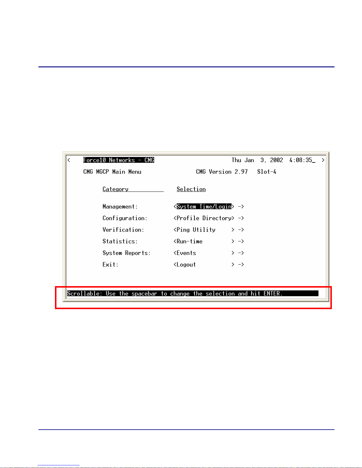
Maneuvering in the System
[TAB] moves from one field to the next.
Keyboard arrows move to the next field in the direction of the arrow.
[ ] Items in brackets are scrollable options. With the [Spacebar] the operator can move
through the selections.
NTER] displays the window for the selected feature or to enter a alphanumeric value.
[E
SC] Exit and return to previous window or to the Main Menu.
[E
Help Bar - is displayed along the bottom of the window and lists options for the
selected feature.
The CMG Router software contains three different field types that may be used in
entering information: scroll, select and edit.
CMG Router - Release 2.97 1-3
Page 18

Introduction
Fields
Fields
Scroll Field
A field enclosed in angle brackets is a scrollable option field. While the field is selected
use the following keystrokes:
[S
[E
Example: Terminal: <generic>
Select Field
PACEBAR] will scroll forward through the options
NTER] will open the option’s window or accept the entered value.
A field followed by –> is a selectable field, which causes an action to be performed,
highlight the field and press [E
NTER] to perform the action, for example, to enter the
Trunk Port Setup screen.
Example: SETUP <Trunk> –>
Some selectable fields, such as Main Menu options, are also a scrollable option field.
For example, <Events>–>. Press the [S
press [E
NTER] to perform the action.
PACEBAR] to select the desired option and then
Edit Field
A field value enclosed in parentheses ( ) may be modified by entering an alphanumeric
character.
Example: SYSTEM NAME: (Adit)
You will note that many editable fields are displayed with a default value. To change
this value, highlight the field and type over the existing entry or press [D
then enter new value. Note: these fields are case sensitive. To enter this value press
[E
NTER].
ELETE] and
1-4 CMG Router - Release 2.97
Page 19
Introduction
Help Bar
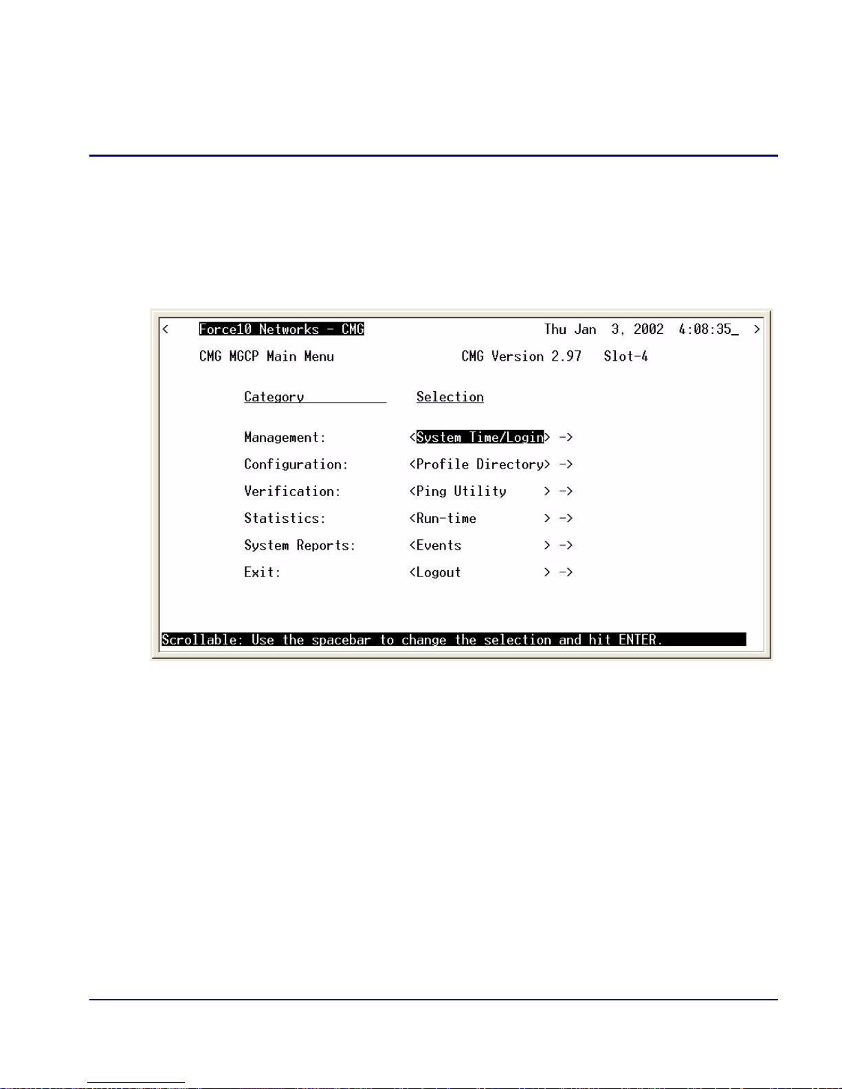
Help Bar
The CMG Router provides field specific help that is displayed at the bottom of the
window. The help text will indicate if the field is scrollable or editable and provide a
brief description of the field. If it is a selectable field, it will state what to do to invoke
the action to be performed.
CMG Router - Release 2.97 1-5
Page 20

Introduction
Connecting to the Router
Connecting to the Router
Establish a Telnet Session
1. Use the telnet {slot} CLI command to connect to the Router card. The
following example is when the router is located in slot 4.
> telnet 4
Connected.
Escape character is '^]'.
Attempting Force10 Networks CMG connection...
CMG [Tue Aug 10, 2004 23:20:36] (<CR> to login)
2. Select [ENTER] or <CR> to log in.
Password >
3. Enter default password (admin) and select [ENTER].
Password >*****
Select a terminal type...
(<space> or <back-space> to toggle, <CR> to accept)
Terminal: <VT100>
4. Select Terminal Type: scroll through options with the [SPACEBAR] and then
NTER] to select. Recommended generic.
[E
Terminal: <generic>
1-6 CMG Router - Release 2.97
Page 21

Introduction
Connecting to the Router
Set a New Password
If you have logged in with a default password, for security reasons the password should
be changed, the system directs the user to do so.
> telnet 4
Connected.
Escape character is '^]'.
Attempting Force10 Networks CMG connection...
CMG [Tue Jan 1, 2002 0:01:06] (<CR> to login)
Password >*****
Select a terminal type...
(<space> or <back-space> to toggle, <CR> to accept)
Terminal: <generic>
You have logged in with a default password.
For security reasons the password should be changed.
Complete the change request and record your new password
for future use.
Password Change Request
(Valid CMG passwords are from 5 to 15 alpha-numeric
characters)
NEW Password >******
RETYPE Password >******
After a successful login, the system prompts the user to change the password from the
default.
1. Type in New Password, and press [E
2. Retype in New Password, and press [E
CMG Router - Release 2.97 1-7
NTER]
NTER]
Page 22

Introduction
Connecting to the Router
1-8 CMG Router - Release 2.97
Page 23

CHAPTER
Management Window
In this Chapter
Management Overview
System Time/Login
Upload/Download
2
Load Defaults
Software Images
Page 24

Management Window
Management Overview
Management Overview
The Management menu contains the system components of the Router software. This
section is used to define security parameters, factory default settings, as well as
providing software loading and configuration settings for the Router.
Management Menu options allow the user to:
Establish the system security features
Install and backup system software
Backup and install configuration settings
Default system parameters to factory settings
NOTE: Two simultaneous sessions are allowed to access the Router software.
For example, one local and one remote (one must be accessing with the VIEW
level).
2-2 CMG Router - Release 2.97
Page 25
Management Window
System Time/Login
System Time/Login
1. Select Management <System Time/Login> from the Main Menu, and select
NTER].
[E
CMG Router - Release 2.97 2-3
Page 26
Management Window
System Time/Login
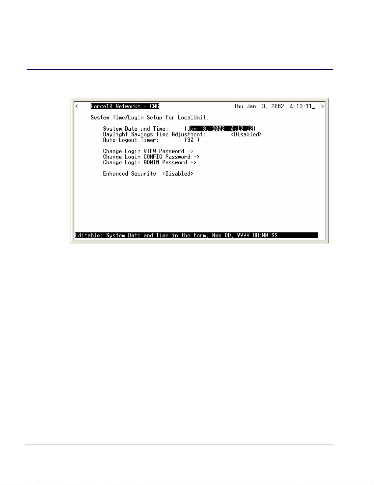
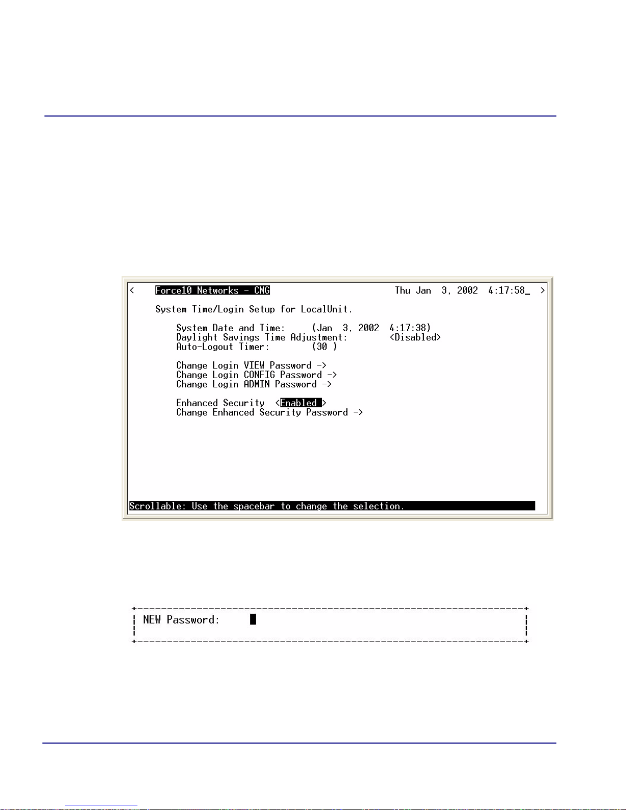
This screen provides the basic system and security options for the Router card.
The Router is equipped with three password levels and an enhanced security
password.
Level 1 VIEW allows the user to view only, no changes are allowed.
Level 2 CONFIG allows the user to view and change all screens.
Level 3 ADMIN allows the user to view and change all screens, terminate
users, as well as change all three passwords.
The Enhanced Security option provides an additional level of security for the
network administrator.
System Date and Time
The time and date values are used for reporting purposes. Enter the date in the
following format: Mmm DD, YYYY. Immediately follow the date with the desired
time entry. The appropriate time format is HH:MM:SS (hour:minute:second). Press
[T
AB] to proceed to the next field.
2-4 CMG Router - Release 2.97
Page 27

Management Window
System Time/Login
Daylight Savings Time Adjustment
Use this field to enable or disable automatic adjustment of the system clock for
Daylight Savings Time.
Auto-Logout Timer
This field defines the minutes of inactivity before the current session is terminated. The
default time is 30 minutes. Type the desired auto-logout time (between 1-255).
NOTE: Any changes that have not been saved will be lost when the timer is
activated.
View Password
Users assigned to this level may view only, no changes are allowed. The default VIEW
password is "public". This field must be unique from the CONFIG and ADMIN
passwords. The field may be a 5-15 characters alphanumeric value.
Config Password
Users assigned to this level may view and change all screens. The default CONFIG
password is "config". This entry must be unique from the VIEW and ADMIN
passwords. The field may be a 5-15 character alphanumeric value.
Admin Password
Users assigned to this level may view and change all screens, as well as change all three
password levels. The default ADMIN password is "admin". This entry must be
unique from the VIEW and CONFIG passwords. The field value may be a
5-15 character alphanumeric value.
NOTE: If the default login passwords are not changed, the user will be
prompted, at each login, to enter new passwords at the CONFIG and ADMIN
levels.
CMG Router - Release 2.97 2-5
Page 28
Management Window
System Time/Login
Enhanced Security
The Enhanced Security option provides another level of password security that
restricts access to the Main Menu via Telnet or the Async port. It can be used by a
Network Administrator to only allow those with the Enhanced Security password to
access the Router. When enabled, this option hides the system login prompt until the
appropriate password is entered.
1. Use the [S
PACEBAR] to select <Enabled> and [TAB] to enter this selection.
2. The Change Enhanced Security Password - > field will display. Select
NTER] to change password. You will be requested to enter the password
[E
twice to confirm.
2-6 CMG Router - Release 2.97
Page 29

Management Window
System Time/Login
When Telneting into the Router the following will appear:
> telnet 4
Connected.
Escape character is '^]'.
1. Type the Enhanced Security Password here. Note: There will be no effect to
the screen here until the correct password is typed in. When the correct
password is typed, no return or other keystroke is needed, the following will
appear:
Password >
WARNING! IF ENHANCED SECURITY IS ENABLED, AND THE ADMINISTRATOR
DOES NOT NOTE THE PASSWORD THERE IS NO WAY TO ACCESS THE ROUTER UNTIL
YOU HAVE RESET THE ROUTER BACK TO ITS DEFAULT SETTINGS, LOSING ALL
CONFIGURATION SETTINGS. SEE SET [ROUTER_CARD-ADDR} DEFAULT.
2. At this point the Router is requesting your Level 1, 2 or 3 User Password. Enter
your password and select [E
NTER] and continue as you would Telnet into the
Router as normal.
Password >******
Select a terminal type...
(<space> or <back-space> to toggle, <CR> to accept)
Terminal: <generic>
CMG Router - Release 2.97 2-7
Page 30

Management Window
Upload/Download
Upload/Download
WARNING! BEFORE LOADING A DOWN-LEVEL OF ROUTER CODE TO AN ADIT
SAVE THE CONFIGURATION TO A FILE. CONFIGURATION MAY BE RESET TO THE
600,
DEFAULT SETTING AND CURRENT CONFIGURATION LOST.
This window allows the network administrator to manage the list of devices and users
who are authorized to perform:
Installation of software
Backup of software and configuration settings (via tftp)
The Router has enhanced management capabilities enabling a network administrator to
perform a Code Upload of new software to the router from a central location via the
LAN or WAN connection using TFTP. A Code Download can also be performed to
save a backup copy (binary image) of the software to a file on a PC. Config Upload
and Config Download can also be performed remotely via TFTP to install and backup
the Router’s settings to and from a binary file.
There is an additional option to upload code to the Router, with the CLI command
load {slot-number} tftp {ip-addr}{"file-name"}
Example: load 4 tftp 172.26.100.25 "rtrall1_10.mgm"
The example loads the software upgrade file "rtrall1_10.mgm" from a
PC to a Router card in slot 4 via TFTP.
2-8 CMG Router - Release 2.97
Page 31

Management Window
Upload/Download
To Set Up the Router for Uploads/Downloads
1. Select Management: <Upload/Download> from the Main Menu, and
NTER].
[E
WARNING! THE CMG ROUTER WILL RETURN TO DEFAULT VALUES IF THE CODE
IS DOWNGRADED TO A RELEASE PREVIOUS TO 2.10.
CMG Router - Release 2.97 2-9
Page 32

Management Window
Upload/Download
2. Select [CTRL A] to add a TFTP Upload/Download User.
Note: The IP Address 1. (* ) will display. The * denotes any IP Address on
the defined Client Site. The user may define a specific IP Address for Uploads/
Downloads by replacing the * or by Adding another Upload/Download User.
3. Select the Client Site
Selections are: <Local LAN> (default) or Remote Unit(s) that have been set up.
2-10 CMG Router - Release 2.97
Page 33

Management Window
Upload/Download
4. For Mode, specify whether the IP Address can perform code uploads/
downloads, config file uploads/downloads, or both.
5. Press [E
SC] to save your changes and return to the Main Menu. These changes
will go into effect immediately.
CMG Router - Release 2.97 2-11
Page 34

Management Window
Upload/Download
Upload/Download Setup Menu Fields
Feature and Release Key Options
Options may be available to purchase, to upgrade the Router. Once this option is
purchased, a key code will be given to enable the feature on this product. For more
information please call Force10 Networks’ Technical Assistance Center.
Reboot After Load Code
Use this option to automatically reboot the Router after software is successfully
installed. A software load verification checks and verifies that the new software is
good before the unit will accept it. If it is determined to be bad or damaged, the
Router will reject it and continue to use the original software.
Reboot After Load Config
Use this option to automatically reboot the Router after a configuration file is
successfully installed.
IP Address
The IP Address field is use to identify which device(s) will be allowed to perform
config and/or code uploads and downloads. A “*” in this field will allow all devices
at the selected Client Site to perform Uploads/Downloads.
Client Site
This field identifies the profile the Router will use to reach the IP Address entered
in the previous field. If <Local LAN> is selected, it indicates the device can be
reached via the LAN. If the device can be reached via a WAN connection, you
should select one of the Remote (WAN) profiles.
Mode
Use this field option to enable uploads/downloads of software and configuration
files for specific IP addresses.
Code – Authorizes the IP Address to perform software uploads and downloads.
When new software is installed on the Router, a software load verification checks
and verifies that the new software is good before the unit will accept it. If it is
determined to be bad or damaged, the Router will reject it and continue to use the
original software. Acceptable binary file extensions are .mgm or .MGM.
2-12 CMG Router - Release 2.97
Page 35

Management Window
Upload/Download
Config – Authorizes the IP Address to perform configuration file uploads and
downloads. For uploads, this selection allows the device(s) in the IP Address field
to transfer or restore a previously backed-up configuration file to the Router via
TFTP. For downloads, this selection defines an IP Address to which a backup copy
of the Router’s configuration can be sent. Acceptable file extensions are “.cfg” or
“.CFG”.
Both – Authorizes the IP Address to perform code and config file uploads/
downloads.
NOTE: Code and Config uploads require a reboot of the unit before the
changes take effect.
CMG Router - Release 2.97 2-13
Page 36

Management Window
Load Defaults
Load Defaults
Use the Load Defaults option to reset the router software to the factory defaults. This
option will delete all configuration settings, including the passwords.
Use the [S
PACEBAR] to choose <Yes> and press [ENTER]. If you have a telnet
connection to the unit, your session will be terminated.
1. Select Management <Load Defaults> from the Main Menu, and select
[E
NTER].
2. A dialog box will display confirming that you want to load factory defaults.
3. Select <YES> with the [S
4. Defaults will be loaded.
2-14 CMG Router - Release 2.97
PACEBAR] and select [ENTER].
Page 37

Management Window
Software Images
Software Images
Use the Software Images option to switch the active with the backup application
images stored in the Router.
1. Select Management <Software Images> from the Main Menu, and select
[E
NTER].
CMG Router - Release 2.97 2-15
Page 38

Management Window
Software Images
Options
Show Current Images - will display the application images stored in the Router
(shown below).
Switch Appl. Images - Switch the active with the backup application images
stored in the router. Note: More than one software image must be loaded (7.0 or
later) for an active and a backup image to display.
2-16 CMG Router - Release 2.97
Page 39

CHAPTER
3
Profile Directory:Router Card Profile
In this Chapter
Overview Network Time Protocol
Configuration SysLog
RIP Mode Receive DNS Resolver
RIP Mode Send Quality of Service
Trunk MGCP
Security VoIP
SNMP Voice Channels
DNS Proxy Dial Plan
Spanning Tree Protocol AIS Feature
Page 40

Profile Directory:Router Card Profile
Main Menu
Overview
Overview
The Router Card Profile of the Profile Directory is used to review/configure base router
features.
Configuration
1. Select Configuration: <Profile Directory> from the Main Menu, and select
[E
NTER].
3-2 CMG Router - Release 2.97
Page 41

Profile Directory:Router Card Profile
Profile
Directory
Window
Router
Card
Configuration
Window
Configuration
2. Select Router CARD <Setup -> and select [ENTER].
The Router Card Configuration Window appears.
CMG Router - Release 2.97 3-3
Page 42

Profile Directory:Router Card Profile
RIP Mode Receive
RIP Mode Receive
Selection is: <RIP1>, <RIP2>, or <RIP1/RIP2>.
RIP Mode Send
Selection is: <RIP1>, <RIP2>, or <RIP1/RIP2>.
Trunk
This window is used to configure the Trunk setup for the Router. Although the Router
is designed to connect remote sites over dedicated connections, the unit supports a
number of different encapsulation protocols simultaneously, including Frame Relay
and PPP. The Router provides the flexibility to allow the user to define which slots will
be used for the selected WAN protocol.
1. Select Trunk < Configure -> and select [E
NTER].
3-4 CMG Router - Release 2.97
Page 43

Profile Directory:Router Card Profile
Trunk
2. All WAN connections will display in this window. To select the WAN
Connection Type,
[TAB] to the Type on the specific WAN Link #, use the
[SPACEBAR] to select the Type (PPP, MLPPP, PPP in Frame Relay, or Frame
Relay 1490) and select
the following field definitions.
[ENTER]. For more information on this window, see
Trunk Setup Menu Fields
WAN Link #
This field displays the WAN Link Number (1-24) for the WAN Connection.
WAN Connection
The WAN Connection displays the current connection of this WAN, in the form
{slot:port:channel}.
CMG Router - Release 2.97 3-5
Page 44

Profile Directory:Router Card Profile
Trunk
WAN Connection Type
Determines the type of protocol encapsulation that will be used for the selected WAN.
PPP
Point-to-Point Protocol. Provides a standard means of encapsulating data packets sent over
a single-channel WAN link. PPP is the standard WAN encapsulation protocol for the interoperability of bridges and routers.
MLPPP
MultiLink PPP. When PPP is selected and a Multilink group is chosen the WAN
Connection Type will display MLPPP.
PPP in Frame Relay
Point-to-Point Protocol encapsulated in Frame Relay.
Frame Relay 1490
A packet-switching protocol for connecting devices on a WAN. Frame Relay networks in the U.S.
support data transfer rates at T1 (1.544 Mbps) and T3 (45 Mbps) speeds. Frame Relay service is
provided for customers who want connections at 56 Kbps to T1 speeds.
Multilink Group
The Multilink Group will specify a trunk as part of a multilink PPP group. Selection is: <None>
or <1> through <24>. Available only when MLPPP connection type is selected.
Data Speed
The Data Speed will specify the data speed for each DS0 in the given trunk. Selection is: <56K>
or <64K>. Default is 64K.
Voice BW Limit %
Defines the maximum percentage of bandwidth allowed on this trunk for voice calls. The
remaining percentage to be reserved for routed or bridged data. Routed or bridged data is
allowed to use any available bandwidth, but it is a lower priority than voice. Range is 0 - 100.
3-6 CMG Router - Release 2.97
Page 45

Profile Directory:Router Card Profile
Trunk
PVC Management
Field Description
Disabled Disables the PVC (Permanent Virtual Circuit) management.
Annex D Frame Relay standard
Poll Interval - Range is between 5-30
Poll Counter - Range is between 1-255
LMI Local Management Interface
Poll Interval - Range is between 5-30
Poll Counter - Range is between 1-255
CMG Router - Release 2.97 3-7
Page 46

Profile Directory:Router Card Profile
Security
Security
1. Select Security < Configure -> and select [ENTER].
3-8 CMG Router - Release 2.97
Page 47

Profile Directory:Router Card Profile
Security
Setup
Window
Security
The fields on this screen may be used to define the authentication process for the local
unit.
CMG Router - Release 2.97 3-9
Page 48

Profile Directory:Router Card Profile
Security
Security Setup Menu Fields
Authentication by Remote
Protocol: CHAP, PAP or NONE
Use this first field to identify the authentication protocol to be used by remote units when
authenticating this unit.
<CHAP> Challenge Handshake Authentication Protocol
<CHAP> Secret
[ENTER] and a NEW Password dialog box will display. Enter a 1 - 15 character
Select
password and select
password and select [ENTER]. Password is now set.
[ENTER] and a RETYPE Password dialog box will display. Retype
<PAP> Password Authentication Protocol
<PAP> Password
Same as above <CHAP> Password.
<NONE > (no authentication protocol) is the default.
User ID
Use this field to define the local unit’s User ID. During the authentication process, the local unit will
send a name or User ID, along with the authentication protocol’s secret or password (see above). Use
[SPACEBAR] to scroll between <Local Profile Name> (the default value) and <Local Custom
the
Name>. If set at <Local Profile Name>, the local unit will send the 11 character unit name which
was defined on the Local (LAN) Profile screen. If this field is set to <Local Custom Name> you may
define a 32 character maximum alphanumeric value to represent the User ID which is sent during the
authentication process. Defining a custom User ID simply gives the end user more flexibility for this
value.
To assign a custom User ID, set the USER ID field to <Local Custom Name> and press [
to ten (10) custom names may be configured.
3-10 CMG Router - Release 2.97
TAB]. Up
Page 49

Profile Directory:Router Card Profile
Security
Authentication of Remote
Protocol: CHAP, PAP or NONE
Use this field to identify the authentication protocol to be used by this unit when authenticating
remote devices.
Local Security Server
Use these fields to identify the local server that is used to authenticate remote devices. This field
is only necessary if you are using either the <RADIUS> or <TACACS+> security
authentication method. If you are not using either of these security methods, the unit will
respond to the authentication requests of remote devices and will accept or reject them based on
their validity.
Type
Use the [SPACEBAR] to choose the security authentication method that you are using.
<None> Use this setting if the local unit will be used to authenticate remote devices. Please note that
you may not use the <None> setting if the Security Server field for a remote device has been set to
<External Server>
<RADIUS>
Will set the server to use the RADIUS (Remote Authentication Dial-In Service)
protocol. RADIUS is a client/server-based authentication software system.
<TACACS+> Will set the server to use the TACACS+ (Terminal Access Controller Access
Control System) protocol. TACACS+ provides services of authentication, authorization
and accounting independently.
Address
Enter the IP Address of the local server that will be used during the authentication process. If <None>
was selected in the <Type> field, this field will be disabled.
Password
Enter the password of the local server that will be used during the authentication process. You must
make sure that the password entered into the server is the same as the value entered here or the
authentication process will fail. If <None> was selected in the <Type> field, this field will be
disabled.
CMG Router - Release 2.97 3-11
Page 50

Profile Directory:Router Card Profile
SNMP
SNMP
By defining specific IP Addresses, devices may be specified to manage the Local Unit
via SNMP.
NOTE: The Router is compatible with the Standard MIB and MIB II.
1. Select SNMP < Configure -> and select [ENTER].
3-12 CMG Router - Release 2.97
Page 51

Profile Directory:Router Card Profile
SNMP
Setup
Window
SNMP
2. Use the SNMP setup window to setup SNMP configurations.
SNMP Setup Menu Fields
SYS Name
Set the value of sysName. Value has a maximum of 64 ASCII characters.
SYS Contact
Set the value of sysContact. Value has a maximum of 64 ASCII characters.
SYS Location
Set the value of sysLocation. Value has a maximum of 64 ASCII characters.
CMG Router - Release 2.97 3-13
Page 52

Profile Directory:Router Card Profile
SNMP
SNMP Community Name(s)
Use these fields to specify the community name, address and access privileges of devices
needing to communicate with the Local Unit (LAN) through SNMP. If no IP Addresses is
defined on this screen, any device may access the local unit using the IP Address assigned on
the Local (LAN) Profile Setup screen, regardless of the specified community name. The values
entered in these fields will be used by the SNMP program as verification of entry into the
Router.
Name
Enter the community name(s) of the device to access the Local (LAN) unit through SNMP.
Community names entered into the SNMP program MUST match the values entered here or access
for remote management will not be allowed. The default community name is public, new community
names can have a maximum of 10 characters.
Address
Enter the corresponding IP Address of the device(s) that were entered in the Name field.
Access
<Read> device is allowed to view the settings, but cannot make any changes
<Write> device is allowed to make changes but not view settings
<Both> device is allowed to both read and write privileges
3-14 CMG Router - Release 2.97
Page 53

Profile Directory:Router Card Profile
SNMP
Setup
Window
SNMP
Setup
Window
SNMP
SNMP Trap Destinations
Select SNMP Trap Destination - > and select [ENTER].
This window defines the SNMP Trap Destinations to which the Router will report alarm
information.
CMG Router - Release 2.97 3-15
Page 54

Profile Directory:Router Card Profile
SNMP
Name
Enter the community name(s) of the devices to which the Router will report. The default community
name is public. To enter a new community name, highlight the field and type the desired value, with
a maximum of 10 characters.
Address
Enter the corresponding IP Address of the device that was entered in the Name field.
Location
<Local LAN>, <RemoteUnit>
Available options are the <Local LAN> and all Remote Units (WAN), defined in the Profile
Directory (there can be up to 30).
3-16 CMG Router - Release 2.97
Page 55

Profile Directory:Router Card Profile
DNS Proxy
DNS Proxy
The DNS (Domain Name Servers) Proxy specifies the IP address of DNS name servers
to be used by the DHCP (Dynamic Host Configuration Protocol) clients.
1. Select DNS Proxy < Configure -> and select [E
NTER].
2. Type [C
CMG Router - Release 2.97 3-17
TRL A] to Add a DNS Proxy.
Page 56

Profile Directory:Router Card Profile
DNS Proxy
3. Enter the appropriate data in the following fields.
4. Select [E
SC] and <YES> to exit the window and save changes.
DNS Proxy Setup Menu Fields
Domain Name
Define a name for the Domain with up to 41 characters.
DNS Server
Enter the IP Address for the DNS Server.
Site
This field lists the Local LAN and all the RemoteUnit that have a profile created for them. Use the
[SPACEBAR] to scroll through the list.
3-18 CMG Router - Release 2.97
Page 57

Profile Directory:Router Card Profile
Spanning Tree Protocol
Spanning Tree Protocol
The Spanning Tree Protocol configures the global setup for using the Spanning Tree
Algorithm as specified in the IEEE 802.1D specification.
1. Select Spanning Tree Protocol < Configure -> and select [E
NTER].
2. To enable Spanning Tree, scroll <Disabled> to <Enabled>, with the
PACEBAR], select [ENTER].
[S
CMG Router - Release 2.97 3-19
Page 58

Profile Directory:Router Card Profile
Spanning Tree Protocol
3. Enter the appropriate data in the following fields.
SPANNING TREE GLOBAL SETUP MENU FIELDS
Bridge Hello Time
The Bridge Hello Time specifies the time interval between transmissions of Topology Change
Notification BPDUs towards the Root when the Bridge is attempting to notify the Designated Bridge
on the LAN to which its Root Port is attached of a topology change. The value can range from 1 to
10 seconds, with a default of 2 seconds.
Bridge Max Age
The Bridge Max Age value specifies the maximum age of received protocol information before it is
discarded. The value can range from 6 to 40 seconds, with a default of 20 seconds.
Bridge Forward Delay
The Bridge Forward Delay is the time spent by a Port in the Listening or Learning States before
transitioning to the Learning or Forwarding State, respectively. The value can range from 4 to 30
seconds, with a default of 15 seconds.
Bridge Priority
The Bridge Priority is the priority part of the bridge identifier. The value can range from 0 to 65535,
with a default of 32768.
3-20 CMG Router - Release 2.97
Page 59

Profile Directory:Router Card Profile
Network Time Protocol
Network Time Protocol
The Network Time Protocol is a protocol which sets the network to a common time
system for Internet hosts, based off of GMT (Greenwich Mean Time).
1. Select Network Time Protocol < Configure -> and select [E
NTER].
2. To enable Network Time Protocol, scroll <Disabled> to <Enabled>, with the
[S
PACEBAR], select [ENTER].
CMG Router - Release 2.97 3-21
Page 60

Profile Directory:Router Card Profile
Network Time Protocol
3. Enter the appropriate data in the following fields.
Network Time Protocol Setup Menu Fields
Network Time Protocol
<Disabled> to disable Network Processing.
<Enabled> to enable Network Processing. The following items appear once enabled.
NTP Server Address
Set the IP address or domain name of the NTP server.
<IP Address> IP address of the NTP server. Setting the NTP server value to 0.0.0.0 will cause the
router to listen to and process NTP broadcasts.
<Domain Name> Domain name of the NTP server. Maximum of 43 characters.
Poll Interval
The Poll Interval specifies the polling of the NTP server to a defined number of seconds. The range
(in seconds) is from 16 to1024 seconds, with a default of 16.
3-22 CMG Router - Release 2.97
Page 61

Profile Directory:Router Card Profile
Network Time Protocol
Time Zone Offset HOURS
The hours Time Zone Offset is used to calculate gateway time from GMT (Greenwich Mean Time).
Range is -12 to 12.
Time Zone Offset MINUTES
The minutes Time Zone Offset is used to calculate gateway time from GMT (Greenwich Mean Time).
Range is 0 to 60.
CMG Router - Release 2.97 3-23
Page 62

Profile Directory:Router Card Profile
SysLog
SysLog
The Syslog client capability enables or disables sending alarm and event messages to
an external Syslog server from the Router.
1. Select SysLog Configure -> and select [E
NTER]
2. To enable SysLog (System Log Message Service), scroll <Disabled> to
<Enable>, with the [S
PACEBAR], select [ENTER].
3-24 CMG Router - Release 2.97
Page 63

Profile Directory:Router Card Profile
SysLog
3. Enter the appropriate data in the following fields.
SysLog Setup Menu Fields
Sys Log
To enable the Sys Log, use the [SPACEBAR] to scroll <Disabled> to <Enabled> and select [TAB]
or [ENTER]. The window will now display the optional settings for SysLog.
Facility
The value can range from 0 to 23, with a default of 16.
Level
The value can range from 0 to 7, with a default of 3. Level 3 is Alarms and level 5 is Events.
Server IP Address
The server IP Address is a unique, dotted decimal notation entry that is used for data routing purposes.
This IP address of the SysLog Server or the Host that has the SysLog Server software running.
CMG Router - Release 2.97 3-25
Page 64

Profile Directory:Router Card Profile
DNS Resolver
DNS Resolver
The DNS Resolver enables the use of the Domain Name Service (DNS) resolver to
convert domain names to IP addresses.
1. Select DNS Resolver Configure -> and select [E
NTER].
3-26 CMG Router - Release 2.97
Page 65

Profile Directory:Router Card Profile
DNS Resolver
2. To enable DNS Resolver, scroll <Disabled> to <Enable>, with the
PACEBAR], select [ENTER].
[S
3. Enter the appropriate data in the following fields.
CMG Router - Release 2.97 3-27
Page 66

Profile Directory:Router Card Profile
DNS Resolver
DNS RESOLVER SETUP MENU FIELDS
DNS Resolver
Disable/enable use of DNS resolver to convert domain names to IP addresses.
My Domain Name
<Enable> <Disable>
Set the default domain that the DNS resolver will add to any name queries that are not fully qualified.
Identifier of up to 43 characters.
My Node Name
Set the CMG card’s host name. Identifier of up to 15 characters.
DNS Primary Server IP Address
Configure IP address of DNS server #1.
DNS Secondary Server IP Address
Configure IP address of DNS server #2.
DNS Resolver Cache Contents
<Flush> - will clear the cache contents
<Display> - will display the cache contents
3-28 CMG Router - Release 2.97
Page 67

Profile Directory:Router Card Profile
DNS Resolver
Static Host List: View or Modify - >
Select this field and press [ENTER]. The system will confirm that you want to save this
configuration. Scroll the <No> to <Yes> to save.
CMG Router - Release 2.97 3-29
Page 68

Profile Directory:Router Card Profile
DNS Resolver
After the configuration is saved, the DNS Static Host window displays and a Static Host can be added
or modified
#
Number of Static Hosts set up. A maximum of 33 can be entered.
IP Address
IP address of the static host.
Host Name
Enter the filter name, with a maximum of 42 characters, no spaces or numbers.
3-30 CMG Router - Release 2.97
Page 69

Profile Directory:Router Card Profile
Quality of Service
Quality of Service
Quality of Service configures the parameters that will be used to recognize routed voice packets
which will be handled with higher priority over other routed data.
For each IP datagram to be routed, the TOS byte from the IP header will be logically AND’d
with the configured TOS mask and compared to the TOS match value. If they match, the
datagram will be handled with a greater priority than other routed data but with lower priority
than its own VoIP data
.
1. Select Quality of Service Configure -> and select [E
NTER].
2. To enable Quality of Service, scroll <Disabled> to <Enable>, with the
[S
PACEBAR], select [ENTER].
CMG Router - Release 2.97 3-31
Page 70

Profile Directory:Router Card Profile
Quality of Service
3. Enter the appropriate data in the following fields.
QUALITY OF SERVICE MENU FIELDS
Routed Voice Priority
<Disable> Disable is the default and will result in no priority handling of routed voice packets.
<Enable> Will all the priority handling of routed voice packets. The following two data fields will
appear for configuration.
TOS Mask - Mask to be applied to the TOS byte in the IP header. In the format of 0x (2 hex digits).
TOS Match - TOS byte match value. In the format of 0x (2 hex digits).
3-32 CMG Router - Release 2.97
Page 71

Profile Directory:Router Card Profile
Quality of Service
The following table contains the appropriate TOS mask and match for various IP
precedence and DiffServ code points:
IP Precedence Mask TOS DiffServ Codepoint Mask TOS
IP Precedence = 0 0xE0 0x00 EF = 101110 0xFC 0xB8
IP Precedence = 1 0xE0 0x20 AF11 = 001010 0xFC 0x28
IP Precedence = 2 0xE0 0x40 AF12 = 001100 0xFC 0x30
IP Precedence = 3 0xE0 0x60 AF13 = 001110 0xFC 0x38
IP Precedence = 4 0xE0 0x80 AF21 = 010010 0xFC 0x48
IP Precedence = 5 0xE0 0xA0 AF22 = 010100 0xFC 0x50
IP Precedence = 6 0xE0 0xC0 AF23 = 010110 0xFC 0x58
IP Precedence = 7 0xE0 0xE0 AF31 = 011010 0xFC 0x68
AF32 = 011100 0xFC 0x70
AF33 = 011110 0xFC 0x78
AF41 = 100010 0xFC 0x88
AF42 = 100100 0xFC 0x90
AF43 = 100110 0xFC 0x98
CMG Router - Release 2.97 3-33
Page 72

Profile Directory:Router Card Profile
MGCP
MGCP
The following window configures all parameters for MGCP.
1. Select MGCP Configure -> and select [E
NTER].
3-34 CMG Router - Release 2.97
Page 73

Profile Directory:Router Card Profile
MGCP
MGCP Setup Menu Fields
MGCP State <Enabled>, <Disabled>
Call Agent
Address: <IP Address> Default IP address for MGCP.
<Domain Name> Default domain name for MGCP. Maximum of 43 characters.
Port: The value can range from 0 to 65535. Default is 2727.
RSIP Scheduler
<Disabled> Disables the RSIP scheduler. Default.
<Local> Enables the RSIP scheduler.
<Recv Only> Enables the RSIP scheduler and listens for commands from the RSIP scheduler server.
When set to <Local> or <Recv Only>, the following RSIP scheduler fields are available:
Normal
The rate at which RSIP messages are sent during Normal mode. The default is 60 per minute.
The range is 0 - 3600. Select units from <MIN>, <HRS>, and <SEC>.
Fallback
The rate at which RSIP messages are sent during Fallback mode. The default is 30 per minute.
The range is 0 - 3600. Select units from <MIN>, <HRS>, and <SEC>.
Threshold
The number of unsuccessful RSIP messages that must be sent to cause the transition from
Normal to Fallback mode. The range is 0 - 255. The default is 3.
Randomize(%)
The randomization percentage to be introduced into the periodic RSIP intervals. The range is
0 - 50. The default is 20. A value of 0 disables randomization.
When set to <Recv Only>, the following additional RSIP scheduler fields are available:
Quiet Timeout (mins)
The amount of time to wait for an RSIP scheduler server message before moving from the Quiet
state to Start state. The range is 0 - 3600 minutes. The default is 60 minutes.
RSIP Server - Address
The IP address or domain name of the RSIP scheduler server. Choose <IP Address> or
<Domain Name>. The IP address must be in the form xxx.xxx.xxx.xxx, where xxx is between
0-255. The domain name must be enclosed in quotes, with a maximum length of 41 characters.
RSIP Server - Port
The port number of the RSIP scheduler server. The default is 2727.
CMG Router - Release 2.97 3-35
Page 74

Profile Directory:Router Card Profile
MGCP
Alt Call Agent
Address: <IP Address> Secondary IP address for MGCP.
<Domain Name> Secondary domain name for MGCP. Maximum of 43 characters.
Port: Secondary port, value can range from 0 to 65535. Default is 2727.
Filter packets from unknown call agents
<Disabled> Disable this filter. Default.
<Enabled> Prevents the CMG from accepting MGCP messages from call agents except those that
have been explicitly configured via Primary or Secondary Call Agent.
Gateway
Address: <Default> DNS domain name/IP address configured for the WAN/LAN interface.
< IP Address> The IP address for the gateway ID in the MGCP header.
<Domain Name> The domain name for the gateway ID in the MGCP header. The
Domain Name form ca be used regardless of wether or not DNS is enabled.
Port: The value can range from 0 to 65535. Default is 2427.
Response Timeout (ms)
The value can range from 0 to 65535. Default is 3000 milliseconds (3 seconds).
Max Retries
The value can range from 1 to 10. Default is 3.
3-36 CMG Router - Release 2.97
Page 75

Profile Directory:Router Card Profile
MGCP
MGCP Interoperability Settings - >
Select this field and press [ENTER].
CMG Router - Release 2.97 3-37
Page 76

Profile Directory:Router Card Profile
MGCP
MGCP Interoperability Menu Fields
Version
<IETF 0.1> IETF MGCP version 0.1, as specified in an IETF MGCP Internet draft.
<IETF 1.0> IETF MGCP version 1.0, as specified in an IETF RFC 3435 (default).
<NCS> Packet Cable MGCP version NCS 1.0
Delay Alert
<Disabled> Allow ringing the terminating subscriber before remote SDP is received (default).
<Enabled> Delay ringing the terminating subscriber until remote SDP is received.
Hookswitch Reporting
<Always> Always report hookswitch events (default).
<On Request> Wait for a request from the call agent before reporting hookswitch events.
Default IETF Event Package
<DTMF> Will set the DTMF package the default.
<General> Will set the General package the default.
<Line> Will set the Line package the default.
PiggyBacking
<Disabled> Disallow sending of piggyback commands (default).
<Enabled> Allow sending of piggybacked commands.
Address Format
<Brackets> MGCP will place brackets around IP addresses (default).
<No Brackets> MGCP will not place brackets around IP addresses.
Dialstring Format
<Commas> Insert commas between digit events (default)
<No Commas> Do not insert commas between digit events.
SDP Mode
<Full> SDP section contain all mandatory lines (v, o, s, c, t, m)
<Minimal> SDP section contain only necessary lines (v, c, m) plus a. Which are the only lines really
used for setting VoIP media stream parameters.
Parse Mode
<Lenient> Do not return an error response in benign situations (default).
< Strict> Return an error response for all protocol errors or requests for unavailable functions.
<Verbose > Do not return an error response in benign situations, but log the event.
3-38 CMG Router - Release 2.97
Page 77

Profile Directory:Router Card Profile
MGCP
Quarantine Notification Handling
<Loop> Can generate multiple notifications to a request notify.
<Step> Generate at most one notification to a request notify (default).
Quarantine Event Handling
<Discard> Discard events that are in the quarantine buffer.
<Process> Process events that are in the quarantine buffer (default).
RSIP Wildcard
<Disabled> Allows interoperability with call agents that require RSIPs to be channel specific.
<Enabled> Enable interoperability with call agents that require the RSIP by issuing a single wildcard
RSIP at those times when all endpoints are transitioning.
RSIP Forced
<Enabled> Enable sending MGCP RSIP RM: Forced messages (default).
<Disabled> Disable sending MGCP RSIP RM: Forced messages.
MGCP Keep-Alive Timeout
Use this menu to configure a keep-alive timer that will cause the CMG to re-send RSIP restart
messages on expiration. When enabled, this countdown timer is reset every time an MGCP message
is received from the Call Agent. On expiration, the CMG will react by starting periodic transmission
of a wildcard RSIP restart MGCP message to each of the configured Call Agents until it is
acknowledged.
Enter 1-255 minutes, 0 to disable.
MGCP Type of Service
Range is 0 to FF hexadecimal.
LCO Codecs
<Disable> - The LCO CODEC list is ignored. The configured CODEC algorithm preference is used
to determine which CODECs are used for a call, and the initial priority ordering
<Enable> - The LCO CODEC list is used to determine which CODECs may be used for the call, and
determines the initial priority ordering of CODECs.
LCO Ptime
<Disable> - The LCO ptime is ignored. The configured CODEC ptime preference, as
defined in the set (router) voip ptime CLI command, is used instead to determine which
ptime is to be used for a call, for a particular CODEC.
<Enable> - The LCO ptime is used to determine which packetization times may be used for the call.
SDP Codec Ordering
<LCO Order> - The SDP CODEC priority order will follow the LCO settings.
<Rdesc Order> - The SDP CODEC priority order will follow the Remote Descriptor.
CMG Router - Release 2.97 3-39
Page 78

Profile Directory:Router Card Profile
MGCP
Voice Algorithm Names - >
Select this field and press [ENTER].
3-40 CMG Router - Release 2.97
Page 79

Profile Directory:Router Card Profile
MGCP
Voice Algorithm Name Fields
Algorithm ID
Standard voice coding algorithms.
Algorithm Definition
g711mu G.711 coding for voice channels mu-law
g711a G.711 coding for voice channels A-law
g729A G.729A coding for voice channels compression At 8 Kbps
g726_16 G.726 coding for voice channels at 16 Kbps
g726_24 G.726 coding for voice channels at 24 Kbps
g726_32 G.726 coding for voice channels at 32 Kbps
g726_40 G.726 coding for voice channels at 40 Kbps
Algorithm Alias
An alias name for the corresponding algorithm. Maximum of 16 characters.
CMG Router - Release 2.97 3-41
Page 80

Profile Directory:Router Card Profile
VoIP
VoIP
The following window configures all VoIP parameters.
1. Select VOIP Configure -> and select [E
NTER].
3-42 CMG Router - Release 2.97
Page 81

Profile Directory:Router Card Profile
VoIP
VoIP Setup Fields
RTP Baseport - Defines the base UDP port to be used when allocating ports for transmitting
or receiving RTP packet streams in VoIP calls. Range is from 1025 - 65535, default is 30000.
RTCP CNAME - Defines the name to be used for the CNAME file of Real-Time Control
Protocol (RTCP) packets.
<Gateway ID> - To use the Gateway ID in the CNAME.
<Custom> - Identifies the gateway, maximum of 63 characters.
SDP Address - Defines the Session Description Interval.
<IP> - Use the CMG IP address.
<Custom> - Use the following address.
<Gateway ID> - Use the MGCP gateway ID.
<Domain Name> - Use the DNS domain name id DNS is enabled or CMG IP address if DNS is
disabled.
CPD Two Way - Defines the Calling Party Disconnect behavior when CPD is enabled for voice
channels (see “Voice Channels” on page 3-47). Note: If CPD is disabled, this setting has no effect.
<Terminating> - Apply CPD to terminating calls only.
<Both> - Apply CPD to both terminating and originating calls.
RTCP Interval(s) - Defines the time interval between RTCP reports. Interval time is in seconds,
range is 0 to 255. If zero, RTCP reporting time is turned off. Default is 5 seconds.
Jitterbuffer Mode - Sets the dynamic delay adjustment to minimize delay through the jitter
buffer, or maintain a static average delay through the jitter buffer.
<Dynamic> - Perform dynamic delay adjustment to minimize delay.
<Static> - Maintain a static average delay, equal to two times the packet time (default).
Hookflash Timeout (ms) - Defines the flash maximum time in milliseconds. This is the time
beyond which a disconnect, rather than a hookflash event, is declared. The default hookflash time is
1500 milliseconds. Range is between 500 and 1500 milliseconds or 0. Flash event processing may be
turned off by setting this parameter to zero.
Compander - Defines the companding algorithm to use with the PCM (G.711) voice stream
to/from the TDM side of a connection. The default companding algorithm is mu-law. The
companding algorithm chosen for the CMG must match the companding used on the associated
TDM-side connected interface channel, i.e. FXS ports and/or T1/E1 channels.
<A-Law> - The companding algorithm used in Europe and elsewhere.
<Mu-Law> - The companding algorithm used in North America.
Call Detail Record
<Disabled> - Disables call detail recording.
<Enabled> - Enables call detail recording.
CMG Router - Release 2.97 3-43
Page 82

Profile Directory:Router Card Profile
VoIP
OSI Interval (ms) - Defines the OSI wink time. Range is 500 to 2500, with a default of 900 ms.
Payload Type Processing - Allows the unit to exchange RTP with non-specification compliant
gateways.
<Lenient> - Allows non-spec gateways.
<Strict> - Does not allow non-spec gateways (default).
G.729A Codec - Enables or disables the G.729 codec.
The CMG. G.729A is available only after the software key for this feature has been entered.
<Disabled> - Disables G.729A codec.
<Enabled> - Enables G.729A codec. This is the default, if the feature software key has been entered.
DTMF Notification Edge - Configures the CMG to notify DTMF digits on the leading or
trailing edge.
<Leading> - Setting this configuration item to leading edge shall cause the CMG to act on DTMF
digits, for collection or notification purposes, at the time the key is pressed.
<Trailing> - Setting this configuration item to trailing edge shall cause the CMG to act on DTMF
digits at the time the key is released.
Ring Delay Time(s) - For ground start systems that answer quickly, this setting provides a delay
during which a ringback signal is returned to the calling end before the call is automatically answered.
Range is 0 to 10 seconds, with a default of 0.
Codec Packing - Defines bit order of RTP voice. Allowing interop with various VoIP equipment.
<Big Endian> - With big endian architecture, the leftmost bytes (lower address) are most significant
(default).
<Little Endian> - With little endian architecture, the rightmost bytes are most significant.
T38 Fax
Note: For the T.38 Fax to operate the following must be set:
CMG. G.729A feature must be enabled, with a software key
Specified voice channel has Fax configured as T38reserved or T38
G.729A codec is enabled
ECM - Enables/Disables the CMG’s fax T.38 Error Correction Mode capability during fax
negotiation for the entire card. Default is <enabled>.
LS Redundancy - Configures the number of duplicate packets to transmit for the Low Speed
V.21-based T.30 fax protocol portion of a T.38 fax call for the entire card. Options are <none>,
<1 packet>, through <8 packets>. Default is <none>.
HS Redundancy - Configures the number of duplicate packets to transmit for the High Speed T.38
fax image data of a fax call for the entire card. Options are <none>, <1 packet>, <2 packets>,
<3 packets>. Default is <none>.
3-44 CMG Router - Release 2.97
Page 83

Profile Directory:Router Card Profile
VoIP
Voice Algorithm Settings - >
Select the field and select [ENTER] to open the window.
CMG Router - Release 2.97 3-45
Page 84

Profile Directory:Router Card Profile
VoIP
VoIP Algorithm Fields
SDP Name - Defines the dynamic payload name to be used for the specified algorithm in the
Session Description Protocol (SDP) part of MGCP connection commands. The name has a maximum
of 16 characters.
RTP Payload Type - Defines the dynamic payload type to be used for the specified algorithm
in the Session Description Protocol (SDP) part of MGCP connection commands.
RTP Ptime (ms) - Defines the default packetization time for specified algorithm. The
packetization time determines the frequency at which RTP packets are transmitted.
For all algorithms other than G.729a, the setting options are <10>, <20> or <30> milliseconds.
For the G.729a the range is <10> through <80> in increments of 10.
3-46 CMG Router - Release 2.97
Page 85

Profile Directory:Router Card Profile
Voice Channels
Voice Channels
The following window configures all parameters for Voice Channels.
1. Select Voice Channels Configure -> and select [E
NTER].
CMG Router - Release 2.97 3-47
Page 86

Profile Directory:Router Card Profile
Voice Channels
Voice Channel Setup Fields
Start Channel - Set the starting channel of which to apply the following voice channel
configuration to. Range is 1 to 48, default is 1. Start channel must be less than or equal to the end
channel.
End Channel - Set the last channel of which to apply the following voice channel configuration
to. Range is 1 to 48. Note: End channel must be equal to or greater than the start channel.
Channel Status - Puts the channel In-Service or Out-of-Service.
<Enabled> - Brings the channel back into service. This will cause an RSIP message to be sent to the
call agent, with the "restart" value for the Restart Method parameter.
<Disabled> - Puts the channel Out-of-Service. Once channel is out-of-service, the call agent cannot
access the endpoint IP associated with the voice channel.
Event Log - Sets the parameters of the log.
<None> - Event log is set to not log errors.
<Errors> - Event log is set to record protocol and other errors only.
<MGCP> - Event log is set to record MGCP protocol events.
<Both> - Event log is set to record MGCP protocol events and errors.
Endpoint Prefix - Defines the common part of the MGCP endpoint name for a voice channel.
The default prefix is "aaln". The Endpoint Prefix is a text string with 1 to 16 characters.
Endpoint Suffix - Defines the variable part of the MGCP endpoint name for a voice channel. The
default suffix is the voice channel number. The Endpoint Suffix is a text string with 1 to 16
characters.
Receive Gain (dB) - Defines the gain on the receive side (packet-to-TDM) voice path for the
specified voice channel. The default gain is 0 dB.
Transmit Gain (dB) - Defines the gain on the transmit side (TDM-to-packet) voice path for the
specified voice channel. The default gain is 0 dB.
Silence Suppression - Enables or disables silence suppression as the default for voice calls for
one or more voice channels.
<Disabled> - Do not use silence suppression unless overridden by the call agent.
<Enabled> - Use silence suppression if possible, with no override by the call agent.
3-48 CMG Router - Release 2.97
Page 87

Profile Directory:Router Card Profile
Voice Channels
Type of Service - Defines the default value for the Type of Service (TOS) in the IP header of
outgoing VoIP packets for the specified channel. The initial default is zero. The definition of the TOS
byte is provided in IETF RFC 791 for the original method of packet classification, and in RFC 2474
for the differentiated service method of classification. In the original classification scheme, the first
(leftmost) 3 bits of the TOS byte represents the "precedence" or priority. Bit 4 (from the left) indicates
optimize for delay. Bit 5 indicates optimize for throughput. Bit 6 indicated optimize for reliability.
DTMF Relay - Enables or disables the relay of DTMF packets as per RFC 2833.
<Disabled> - Disables DTMF Relay as the default for voice calls.
<Enabled> - Enables DTMF Relay as the default for voice calls. Default.
Slash - Removes implied slash between endpoint and suffix and prefix.
<Disabled> - Suppress the use of a slash between the endpoint prefix and suffix.
<Enabled> - Insert a slash between the endpoint prefix and suffix.
Calling Party Disc - When the CMG receives a disconnect message, and the leg being
disconnected is the only leg of a call remaining, CPD is applied to the call as follows:
<Disabled> - Do not apply CPD.
<Enabled> - Apply CPD. (Use the "CPD Two Way" setting, described on page 3-43, to specify
whether CPD is applied to both the terminating and originating call or just to the terminating call.)
<Osi> - Apply CPD to either terminating or originating calls, only if the channel has received an OSI
signal event notification.
Fax - Sets the fax handling for this endpoint.
Note: For the Fax to operate the following must be set:
CMG G.729A feature must be enabled, with a software key
Specified voice channel has Fax configured as T38reserved or T38
G.729A codec is enabled
<none> - Fax calls to/from the voice channel are handled as normal voice calls. Note: G711mu is
the only codec that will result in good fax and modem calls. In this mode echo cancellation must
be OFF for modem calls, and ON for fax calls.
<bypass> - Fax calls to/from the voice channel are handled using the fax bypass procedure (Gateway-
controlled fax bypass using NSEs). After a call is connected to the channel in voice mode, if a fax
tone is detected on the channel, the CMG will transmit NSEs to the remote gateway to tell it to switch
to a G.711 codec and then it will switch to a G.711 codec itself for that channel and disable silence
suppression. For the switchover to be successful, the remote gateway must also switchover to G.711.
The form of G.711 (mu-law or A-law) to which the codec is switched will be the form which has the
highest priority in the negotiated codec list. Note: Either G711mu or G711a must be on the
algorithm preference list for Fax Bypass to work.
CMG Router - Release 2.97 3-49
Page 88

Profile Directory:Router Card Profile
Voice Channels
<T38> - Fax calls to/from the voice channel are handled using T.38 method (Gateway-controlled
T.38 fax relay using NSEs) if DSP resources are available. When no DSP resources are available
(6 active T.38 fax calls) the card will reject the T.38 connect request and revert the channel to fax
bypass mode using the G.711 codec.
<T38reserved> - Fax calls to/from the voice channel are handled using T.38 method (Gatewaycontrolled T.38 fax relay using NSEs). Since this method pre-allocates DSP resources, the user can
only configure up to 6 T.38 connections per card.
Modem - Sets the modem handling for this endpoint.
<none> - Modem calls to/from the voice channel are handled as normal voice calls. Note: G711mu
is the only codec that will result in good fax and modem calls. In this mode echo cancellation
must be OFF for modem calls and ON for fax calls.
<bypass> - Modem calls to/from the voice channel are handled using the modem bypass procedure
(Gateway-controlled modem bypass using NSEs). After a call is connected to the channel in voice
mode, if a modem tone is detected on the channel, the CMG will transmit NSEs to the remote gateway
to tell it to switch to a G.711 codec and then it will switch to a G.711 codec itself for that channel and
disable silence suppression. For the switchover to be successful, the remote gateway must also
switchover to G.711. The form of G.711 (mu-law or A-law) to which the codec is switched will be
the form which has the highest priority in the negotiated codec list, or the one offered by the far end
gateway. Note: for modem calls (not fax calls), the gateway that initiated the bypass
(terminating gateway) then sends a "Disable echo cancellation" NSEs (193). After this both
gateways should turn off echo cancellation.
Signaling Type
<FXS LS> - FXS Loop Start. Default.
<FXS GS> - FXS Ground Start.
Short Inter Digit - Configures the short interdigit user dialing timeout on a voice channel. This
is the time allowed between dialed digits when the T or I address template specification is in effect.
For example, if the address specification is "xxxxT", and 4 digits have been dialed, this short timeout
is in effect. If the timer expires, the call will be routed to the destination. If another digit is dialed
before the timer expires, address processing will continue, using the long interdigit timeout. The
range is 1-10 seconds, with a default of 4.
Long Inter Digit - Configures the short interdigit user dialing timeout on a voice channel. This
is the total time allowed between dialed digits after the first, unless short timing is in effect. If the
originator does not dial the next digit in this time period, the call is torn down. The range is 1-60
seconds, with a default of 16.
3-50 CMG Router - Release 2.97
Page 89

Profile Directory:Router Card Profile
Voice Channels
Echo Cancellation - Enables/disables echo cancellation as the default for voice calls for a voice
channel.
<Disabled> - Disable echo cancellation as the default for voice calls.
<Enabled> - Enables echo cancellation as the default for voice calls. Default.
Echo Tail (ms) - Defines the maximum round-trip delay expected in the voice path between the
CMG and the phone, including acoustical delay at the phone. Options are: <8>, <16>, <24>, <32>
and <64>. Default is <16> milliseconds.
VOIP Algorithm Preference Order - Defines the order preference of voice coding
algorithms for VoIP calls, on the specified voice channel(s). Up to 6 algorithms can be listed, in order
of preference. This list limits the acceptable codecs for a particular voice channel to those specified.
This can be used to limit voice channels that have a modem or fax machine attached to use only
G.711. Default settings list all algorithms, selections can be changed to none.
RFC2833 Options
Signals
<disable> - Disable signaling in RTP payloads. Default.
<abcd> - Use abcd signaling in RTP payloads.
Payload Type
<default> - Will be the value of the DTMF relay telephone event payload type. Default.
<number> - Range between 96-127.
Repeat Count
Set the number of initial RTP message repeats at the time of signal transition. Range is 0-10
repeats. Default is 2.
Note: a repeat of 2 times, in essence is a message, followed by 2 repeats.
Repeat Interval
Set the interval of RTP messages at the time of transition in milliseconds. Range is 1-50
milliseconds, with a default of 5.
Refresh Interval
Set the periodic refresh interval of RTP signaling states. Range is 500-4000 milliseconds, with
a default of 4000.
CMG Router - Release 2.97 3-51
Page 90

Profile Directory:Router Card Profile
Dial Plan
Dial Plan
The following window configures the dial plan on the CMG Router card. A CMG dial
plan is responsible for user dialing timeouts and digit maps.
1. Select Dial Plan < Configure -> and select [Enter].
3-52 CMG Router - Release 2.97
Page 91

Profile Directory:Router Card Profile
Dial Plan
Dial Plan Menu Fields
Short Inter Digit
Specify the time allowed between dialed digits when the T or I address template specification is in
effect. For example, if the address specification is "xxxxT", and 4 digits have been dialed, this short
timeout is in effect. If the timer expires, the call will be routed to the destination. If another digit is
dialed before the timer expires, address processing will continue, using the long interdigit timeout.
Enter the number of seconds (1-10). The default is 4.
Long Inter Digit
Specify the total time allowed between dialed digits after the first, unless short timing is in effect. If
the originator does not dial the next digit in this time period, the call is torn down. Enter the number
of seconds (1-60). The default is 16.
CMG Router - Release 2.97 3-53
Page 92

Profile Directory:Router Card Profile
AIS Feature
AIS Feature
The AIS Feature enables generation of a T1 alarm indication signal (AIS) on the dropside MGCP-controlled voice trunk (T1) when an error condition exists on the networkside Ethernet interface. When this feature is enabled, the CMG card sends an AIS
request to the controller under either of the following circumstances:
The CMG Ethernet port enters a failed state (LOS)
Communication with the Call Agent fails (RSIP or NTFY no response)
In response, the controller activates AIS on all T1 interfaces that are cross-connected
to the CMG VoIP ports. The controller generates an alarm indicating that the T1 is in
AIS due to network-side loss of connectivity. When the failure condition clears, the
controller clears AIS on the T1 interfaces and clears the associated alarm.
MGCP Lockout
MGCP Lockout enables lockout of all MGCP VoIP channels on the network-side
Ethernet interface when an error condition exists on the drop-side T1 voice trunk.
When the MGCP Lockout feature is enabled, the controller sends a "set lockout mode
on" message to the CMG card whenever a T1 that is cross-connected to CMG VoIP
ports is in an alarm state. In response, the CMG locks out all corresponding MGCP
channels. The controller generates a major alarm indicating that the CMG is in a
lockout condition due to a drop-side T1 failure. When the T1 alarm clears, the
controller sends a "set lockout mode off" message to the CMG. In response, the CMG
clears the lockout state.
3-54 CMG Router - Release 2.97
Page 93

Profile Directory:Router Card Profile
AIS Feature
Select AIS Feature < Configure -> and select [Enter].
CMG Router - Release 2.97 3-55
Page 94

Profile Directory:Router Card Profile
AIS Feature
AIS Feature Setup Fields
AIS Feature
<Disabled> - Disable T1 AIS. Default.
<Enabled> - Enable T1 AIS.
MGCP Lock Out
<Disabled> - Disable MGCP lockout. Default.
<Enabled> - Enable MGCP lockout.
3-56 CMG Router - Release 2.97
Page 95

CHAPTER
4
Profile Directory:Local Profile
In this Chapter
Overview
LAN (Local) Profile Setup
Static Networks
Static Addresses
Filters
Firewall Filters (Local Profile)
Advertise Network/Server
DHCP Server/Client/Relay
LAN Collision Threshold
Spanning Tree
Secondary IP Address
Link Speed
Page 96

Profile Directory:Local Profile
Overview
Overview
The Local (LAN) Profile Setup is found in Configuration <Profile Directory>/
LocalUnit LAN <Setup ->.
4-2 CMG Router - Release 2.97
Page 97

Profile Directory:Local Profile
Local Profile window
Overview
CMG Router - Release 2.97 4-3
Page 98

Profile Directory:Local Profile
LAN (Local) Profile Setup
LAN (Local) Profile Setup
The LAN Profile is the largest, most detailed portion of the Router software. The fields
on this screen allow definition of how data transmission will occur on the unit’s LAN
port. This includes defining the protocol(s) that it will use to send and receive data,
defining security protocols, specifying which LAN servers and networks will be
advertised to WAN units, and establishing specific data filtering options.
The LAN profile is used in conjunction with the WAN profiles. The WAN profiles
identify which remote units the local unit can communicate with, as well as the data
transmission requirements of each remote.
In addition to the fields on this screen, there are several other areas that directly relate
to the communication abilities of the unit. You may use the fields at the bottom of this
screen to access the following areas:
Defining static addresses at the local unit
Establishing static networks
Establishing Remote (WAN) advertising
Establishing DHCP Server/Client/Relay agent parameters
Defining firewalls
Defining data filters
The Router can accommodate a maximum of 500 filters, such as those created when
establishing static routes or data filters. The following entries consume a filter:
Configured address, custom and protocol filters
Static IP networks and static IPX networks
Enabling any learned items listed on the Advertise Network/Server screen or
Filter Network/Server screen
Static IP and MAC Addresses
Firewall filters
In a large network, it is necessary to selectively use each of these options so that the
number of configured filters is within the maximum allowed.
The Local Profile is used to define the Local (LAN) port parameters for the unit at the
present location.
4-4 CMG Router - Release 2.97
Page 99

Profile Directory:Local Profile
Local
window
Profile
LAN
Profile
Window
LAN (Local) Profile Setup
To Set Up a Local Profile:
1. Select Configuration: <Profile Directory> from the Main Menu, and select
NTER].
[E
2. Select LAN < Setup -> and select [E
NTER].
CMG Router - Release 2.97 4-5
Page 100

Profile Directory:Local Profile
LAN (Local) Profile Setup
Local Profile Setup Menu Fields
Profile Setup for (LocalUnit)
The (LocalUnit) is the default name for this unit and will be used during the authentication
process to ensure this unit’s identity. This name can easily by changed by simply typing over
the "LocalUnit" and saving when closing this window. This name can be up to 11 characters.
Protocol
This column includes three protocol options, IP, IPX and Other. These protocols are used to
define Frame Types and LAN Network Updates to be used by this unit.
Frame Types
Define the frame type of the packets that are sent and received by the Router. If a packet is
received formatted in a frame type that has not been enabled, the Router will not accept the data.
NOTE: Multiple frame types may be supported simultaneously for IPX and
Other protocols.
802.2
When selected (X) this Router may send and receive packets that match the 802.2 format. The 802.2
format complies with IEEE specifications.
Eth II
When selected (X) this Router may send and receive packets that match the Ethernet II format. Note
that the IP protocol commonly uses this format.
SNAP
When selected (X) this Router may send and receive packets that match the SNAP (Subnet Network
Address Protocol) format.
802.3
When selected (X) this Router may send and receive packets that match Novell’s X802.3 format.
LAN Network Updates
Use the LAN Network Updates field to determine whether the Local (LAN) unit will learn, via
RIP and SAP packets, which networks and services are attached to the local LAN, and whether
Remote (WAN) networks and services will be advertised to the LAN. If this information is
learned, it may be advertised to remote devices if advertising is established. Use the
[SPACEBAR] to select from the following options: <Both>, <Neither>, <Send> and
<Receive>.
4-6 CMG Router - Release 2.97
 Loading...