

Page 1

P-Series Installation and
Operation Guide
Version 2.3.1.2 May 27, 2008 PN: 100-00055-01
Page 2
Copyright 2008 Force10 Networks®
All rights reserved. Printed in the USA. January 2008.
Force10 Networks® reserves the r
Trademarks
Force10 Networks® and E-Series® are registered trademarks of Force10 Networks, Inc. Force10, the Force10 logo, and P-Series are
trademarks of Force10 Networks, Inc. All other brand and product names are registered trademarks or trademarks of their respectiv e holder s.
Statement of Conditions
In the interest of improving internal design, opera
products described in this document without notice. Force10 Networks does not assume any liability that may occur due to the use or
application of the product(s) described herein.
USA Federal Communications Commission
This equipment has been tested and found to comp
limits are designated to provide reasonable protection against harmful interference when the equipment is operated in a commercial
environment. This equipment generates, uses, and can radiate radio frequency energy. If it is not installed and used in accordance to the
instructions, it may cause harmful interference to radio communications. Operation of this equipment in a residential area is likely to cause
harmful interference, in which case users will be required to take whatever measures necessary to correct the interference at their own
expense.
Properly shielded and grounded cables
responsible for any radio or television interference caused by using other than recommended cables and connectors or by unauthorized
changes or modifications in the equipment. Unauthorized changes or modification could void the user’s authority to operate the equipment.
This device complies with Part 15 of the FCC Rules. Operation is subject
harmful interference, and (2) this device must accept any interference received, including interference that may cause undesired operation.
Canadian Department of Communication Statement
The digital apparatus does not
Regulations of the Canadian Department of Communi cations.
Attention: Le present ap
numeriques de la Class A prescrites dans le Reglement sur les interferences radioelectriques etabli par le ministere des Communications du
Canada.
European Union EMC Directive C
This product is in conformity with the pr
Member States relating to electromagnetic compatibility. Force 10 Networks can not accept responsibility for any failure to satisfy the
protection requirements resulting from a non-recommended modification of this product, including the fitting of non-Force10 option cards.
This product has been tested and found to comply
European Standard EN 55022. The limits for Class A equipment were derived for commercial and industrial environments to provide
reasonable protection against interference with licensed communication equipment.
pareil numerique n’ emet pa
ight to change, modify, revise this publication without notice.
tional function, and/or reliability, Force10 Networks reserves the right to make changes to
(FCC) Statement
ly with the limits for a Class A digital device, pursuant to Part 15 of the FCC rules. These
and connectors
exceed the Class A limits for radio noise emissions from digital apparatus set out in the Radio Interference
onformance Statement
otection requirements of EU Council Directive 89/336/EEC on the approximation of the laws of the
must be used in order to meet FCC emission limits. Force10 Networks is not
to the following two conditions: (1) this device may not cause
s de perturbations radioelectriques depassant les normes applicables aux appareils
with the limits for Class A Information Technology Equipment according to CISPR 22/
Warning: This device is a Class A product. In a domestic environment, this device can cause radio interference , in
which case, the user may be required to take appropriate measures.
VCCI Compliance for Class A Equipment (Japan)
This is Class A product based on the standard
(VCCI). If this equipment is used in a domestic environment, radio disturbance may arise. When such trouble occurs, the user may be
required to take corrective actions.
Danger: AC Po
cords with any unauthorized hardware.
wer cords are for use with Force10 Networks equipment only, do not use Force10 Networks AC Power
of the Voluntary Control Council For Interference by Information Technology Equipment
Page 3

Content s
Contents . . . . . . . . . . . . . . . . . . . . . . . . . . . . . . . . . . . . . . . . . . . . . . . . . . . . . . . . . . . . . . . . . . . 3
Preface
About this Guide . . . . . . . . . . . . . . . . . . . . . . . . . . . . . . . . . . . . . . . . . . . . . . . . . . . . . . . . . . . . 7
Objectives . . . . . . . . . . . . . . . . . . . . . . . . . . . . . . . . . . . . . . . . . . . . . . . . . . . . . . . . . . . . . . . . . . . . . . 7
Audience . . . . . . . . . . . . . . . . . . . . . . . . . . . . . . . . . . . . . . . . . . . . . . . . . . . . . . . . . . . . . . . . . . . . . . . 7
Conventions . . . . . . . . . . . . . . . . . . . . . . . . . . . . . . . . . . . . . . . . . . . . . . . . . . . . . . . . . . . . . . . . . . . . . 7
Information Symbols . . . . . . . . . . . . . . . . . . . . . . . . . . . . . . . . . . . . . . . . . . . . . . . . . . . . . . . . . . . . . . 8
Related Documents . . . . . . . . . . . . . . . . . . . . . . . . . . . . . . . . . . . . . . . . . . . . . . . . . . . . . . . . . . . . . . . 8
Additional Resources . . . . . . . . . . . . . . . . . . . . . . . . . . . . . . . . . . . . . . . . . . . . . . . . . . . . . . . . . . . . . . 8
Chapter 1
Installation . . . . . . . . . . . . . . . . . . . . . . . . . . . . . . . . . . . . . . . . . . . . . . . . . . . . . . . . . . . . . . . . . 9
System Specifications . . . . . . . . . . . . . . . . . . . . . . . . . . . . . . . . . . . . . . . . . . . . . . . . . . . . . . . . . . . . 10
Physical Connections . . . . . . . . . . . . . . . . . . . . . . . . . . . . . . . . . . . . . . . . . . . . . . . . . . . . . . . . . . . . 10
Booting . . . . . . . . . . . . . . . . . . . . . . . . . . . . . . . . . . . . . . . . . . . . . . . . . . . . . . . . . . . . . . . . . . . . . . . 12
Configuration . . . . . . . . . . . . . . . . . . . . . . . . . . . . . . . . . . . . . . . . . . . . . . . . . . . . . . . . . . . . . . . . . . . 12
Security Check . . . . . . . . . . . . . . . . . . . . . . . . . . . . . . . . . . . . . . . . . . . . . . . . . . . . . . . . . . . . . . . . . 12
Upgrading Software . . . . . . . . . . . . . . . . . . . . . . . . . . . . . . . . . . . . . . . . . . . . . . . . . . . . . . . . . . . . . . 12
Chapter 2
Getting Started. . . . . . . . . . . . . . . . . . . . . . . . . . . . . . . . . . . . . . . . . . . . . . . . . . . . . . . . . . . . . 15
Returning to the Default Configuration . . . . . . . . . . . . . . . . . . . . . . . . . . . . . . . . . . . . . . . . . . . . . . . 15
Chapter 3
Introduction . . . . . . . . . . . . . . . . . . . . . . . . . . . . . . . . . . . . . . . . . . . . . . . . . . . . . . . . . . . . . . . 17
Hardware Architecture Overview . . . . . . . . . . . . . . . . . . . . . . . . . . . . . . . . . . . . . . . . . . . . . . . . . . . . 17
Types of Rules . . . . . . . . . . . . . . . . . . . . . . . . . . . . . . . . . . . . . . . . . . . . . . . . . . . . . . . . . . . . . . . . . . 18
Sample Rules and Firmware . . . . . . . . . . . . . . . . . . . . . . . . . . . . . . . . . . . . . . . . . . . . . . . . . . . . . . . 18
Rule Management . . . . . . . . . . . . . . . . . . . . . . . . . . . . . . . . . . . . . . . . . . . . . . . . . . . . . . . . . . . . . . . 19
Deploying the P-Series . . . . . . . . . . . . . . . . . . . . . . . . . . . . . . . . . . . . . . . . . . . . . . . . . . . . . . . . . . . 19
Inline Deployment . . . . . . . . . . . . . . . . . . . . . . . . . . . . . . . . . . . . . . . . . . . . . . . . . . . . . . . . . . . . 20
Fail-safe Deployment . . . . . . . . . . . . . . . . . . . . . . . . . . . . . . . . . . . . . . . . . . . . . . . . . . . . . . . . . 20
Highly-available Deployment . . . . . . . . . . . . . . . . . . . . . . . . . . . . . . . . . . . . . . . . . . . . . . . . . . . . 21
Passive Deployment . . . . . . . . . . . . . . . . . . . . . . . . . . . . . . . . . . . . . . . . . . . . . . . . . . . . . . . . . . 21
Capturing Matched Traffic . . . . . . . . . . . . . . . . . . . . . . . . . . . . . . . . . . . . . . . . . . . . . . . . . . . . . . . . . 22
Capturing to a Host CPU . . . . . . . . . . . . . . . . . . . . . . . . . . . . . . . . . . . . . . . . . . . . . . . . . . . . . . . 23
P-Series Installation and Operation Guide, version 2.3.1.2 3
Page 4

Mirroring to Another Device . . . . . . . . . . . . . . . . . . . . . . . . . . . . . . . . . . . . . . . . . . . . . . . . . . . . 24
Chapter 4
Graphical User Interface . . . . . . . . . . . . . . . . . . . . . . . . . . . . . . . . . . . . . . . . . . . . . . . . . . . . . 25
GUI Commands . . . . . . . . . . . . . . . . . . . . . . . . . . . . . . . . . . . . . . . . . . . . . . . . . . . . . . . . . . . . . . . . . 26
Managing Rules, Policies, and Firmware . . . . . . . . . . . . . . . . . . . . . . . . . . . . . . . . . . . . . . . . . . . . . 27
Editing Dynamic Rules with the GUI . . . . . . . . . . . . . . . . . . . . . . . . . . . . . . . . . . . . . . . . . . . . . . . . . 28
Managing Capture/Forward Policies with the GUI . . . . . . . . . . . . . . . . . . . . . . . . . . . . . . . . . . . . . . . 29
Selecting Firmware with the GUI . . . . . . . . . . . . . . . . . . . . . . . . . . . . . . . . . . . . . . . . . . . . . . . . . . . . 30
Runtime Statistics . . . . . . . . . . . . . . . . . . . . . . . . . . . . . . . . . . . . . . . . . . . . . . . . . . . . . . . . . . . . . . . 31
Reloading Firmware . . . . . . . . . . . . . . . . . . . . . . . . . . . . . . . . . . . . . . . . . . . . . . . . . . . . . . . . . . . . . 33
Chapter 5
Web-based Management. . . . . . . . . . . . . . . . . . . . . . . . . . . . . . . . . . . . . . . . . . . . . . . . . . . . . 35
Launching the P-Series Node Manager . . . . . . . . . . . . . . . . . . . . . . . . . . . . . . . . . . . . . . . . . . . . . . 35
Web-browser Security Certificates . . . . . . . . . . . . . . . . . . . . . . . . . . . . . . . . . . . . . . . . . . . . . . . 37
Managing the P-Series using Node Manager . . . . . . . . . . . . . . . . . . . . . . . . . . . . . . . . . . . . . . . . . . 37
Monitoring System Performance . . . . . . . . . . . . . . . . . . . . . . . . . . . . . . . . . . . . . . . . . . . . . . . . . 38
Managing Firmware Images . . . . . . . . . . . . . . . . . . . . . . . . . . . . . . . . . . . . . . . . . . . . . . . . . . . . 39
Managing the Network Interface Card . . . . . . . . . . . . . . . . . . . . . . . . . . . . . . . . . . . . . . . . . . . . 39
Managing Policies . . . . . . . . . . . . . . . . . . . . . . . . . . . . . . . . . . . . . . . . . . . . . . . . . . . . . . . . . . . . 41
Chapter 6
Network Security Monitoring . . . . . . . . . . . . . . . . . . . . . . . . . . . . . . . . . . . . . . . . . . . . . . . . . 43
Installing the Sguil System . . . . . . . . . . . . . . . . . . . . . . . . . . . . . . . . . . . . . . . . . . . . . . . . . . . . . . . . 44
Installing the Sguil Sensor . . . . . . . . . . . . . . . . . . . . . . . . . . . . . . . . . . . . . . . . . . . . . . . . . . . . . . 44
Installing the Sguil Server . . . . . . . . . . . . . . . . . . . . . . . . . . . . . . . . . . . . . . . . . . . . . . . . . . . . . . 44
Installing the Sguil Client . . . . . . . . . . . . . . . . . . . . . . . . . . . . . . . . . . . . . . . . . . . . . . . . . . . . . . . 45
Installation Files . . . . . . . . . . . . . . . . . . . . . . . . . . . . . . . . . . . . . . . . . . . . . . . . . . . . . . . . . . . . . . . . . 46
Running the Sguil System . . . . . . . . . . . . . . . . . . . . . . . . . . . . . . . . . . . . . . . . . . . . . . . . . . . . . . . . . 47
Running the Sguil Sensor . . . . . . . . . . . . . . . . . . . . . . . . . . . . . . . . . . . . . . . . . . . . . . . . . . . . . . 47
Running the Sguil Server . . . . . . . . . . . . . . . . . . . . . . . . . . . . . . . . . . . . . . . . . . . . . . . . . . . . . . 48
Running the Sguil Client . . . . . . . . . . . . . . . . . . . . . . . . . . . . . . . . . . . . . . . . . . . . . . . . . . . . . . . 49
Chapter 7
Command Line Interface. . . . . . . . . . . . . . . . . . . . . . . . . . . . . . . . . . . . . . . . . . . . . . . . . . . . . 51
CLI Commands . . . . . . . . . . . . . . . . . . . . . . . . . . . . . . . . . . . . . . . . . . . . . . . . . . . . . . . . . . . . . . . . . 51
Editing Dynamic Rules with the CLI . . . . . . . . . . . . . . . . . . . . . . . . . . . . . . . . . . . . . . . . . . . . . . . . . 51
MAC Rewriting . . . . . . . . . . . . . . . . . . . . . . . . . . . . . . . . . . . . . . . . . . . . . . . . . . . . . . . . . . . . . . . . . . 51
Removing VLAN Tags . . . . . . . . . . . . . . . . . . . . . . . . . . . . . . . . . . . . . . . . . . . . . . . . . . . . . . . . . . . . 53
4 Contents
Page 5

Chapter 8
Compiling Rules. . . . . . . . . . . . . . . . . . . . . . . . . . . . . . . . . . . . . . . . . . . . . . . . . . . . . . . . . . . . 55
Creating Rules Files . . . . . . . . . . . . . . . . . . . . . . . . . . . . . . . . . . . . . . . . . . . . . . . . . . . . . . . . . . . . . 55
Rules Capacity . . . . . . . . . . . . . . . . . . . . . . . . . . . . . . . . . . . . . . . . . . . . . . . . . . . . . . . . . . . . . . . . . 55
Compiling Rules . . . . . . . . . . . . . . . . . . . . . . . . . . . . . . . . . . . . . . . . . . . . . . . . . . . . . . . . . . . . . . . . 55
Starting and Stopping the pnic-Compiler . . . . . . . . . . . . . . . . . . . . . . . . . . . . . . . . . . . . . . . . . . . . . . 60
Configuration and Generated Files . . . . . . . . . . . . . . . . . . . . . . . . . . . . . . . . . . . . . . . . . . . . . . . . . . 61
Firmware Filenames . . . . . . . . . . . . . . . . . . . . . . . . . . . . . . . . . . . . . . . . . . . . . . . . . . . . . . . . . . . . . 62
Compiler Errors . . . . . . . . . . . . . . . . . . . . . . . . . . . . . . . . . . . . . . . . . . . . . . . . . . . . . . . . . . . . . . . . . 62
Chapter 9
Writing Rules . . . . . . . . . . . . . . . . . . . . . . . . . . . . . . . . . . . . . . . . . . . . . . . . . . . . . . . . . . . . . . 63
Snort Rule Syntax . . . . . . . . . . . . . . . . . . . . . . . . . . . . . . . . . . . . . . . . . . . . . . . . . . . . . . . . . . . . . . . 63
Snort Rule Headers . . . . . . . . . . . . . . . . . . . . . . . . . . . . . . . . . . . . . . . . . . . . . . . . . . . . . . . . . . . 63
Snort Rule Options . . . . . . . . . . . . . . . . . . . . . . . . . . . . . . . . . . . . . . . . . . . . . . . . . . . . . . . . . . . 66
P-Series Rule Syntax . . . . . . . . . . . . . . . . . . . . . . . . . . . . . . . . . . . . . . . . . . . . . . . . . . . . . . . . . . . . 66
P-Series Supported Snort Keywords . . . . . . . . . . . . . . . . . . . . . . . . . . . . . . . . . . . . . . . . . . . . . . . . . 66
Writing Stateful Rules . . . . . . . . . . . . . . . . . . . . . . . . . . . . . . . . . . . . . . . . . . . . . . . . . . . . . . . . . . . . 68
Stateful Matching . . . . . . . . . . . . . . . . . . . . . . . . . . . . . . . . . . . . . . . . . . . . . . . . . . . . . . . . . . . . . 68
Stateful Rule Examples . . . . . . . . . . . . . . . . . . . . . . . . . . . . . . . . . . . . . . . . . . . . . . . . . . . . . . . . 70
The meta.rules File . . . . . . . . . . . . . . . . . . . . . . . . . . . . . . . . . . . . . . . . . . . . . . . . . . . . . . . . . . . 71
Support for Snort's flow Keyword . . . . . . . . . . . . . . . . . . . . . . . . . . . . . . . . . . . . . . . . . . . . . . . . . . . 71
Handling Segmentation Evasion . . . . . . . . . . . . . . . . . . . . . . . . . . . . . . . . . . . . . . . . . . . . . . . . . . . . 71
Support for Snort's within Keyword . . . . . . . . . . . . . . . . . . . . . . . . . . . . . . . . . . . . . . . . . . . . . . . . . . 72
Anomalous TCP Flags . . . . . . . . . . . . . . . . . . . . . . . . . . . . . . . . . . . . . . . . . . . . . . . . . . . . . . . . . . . . 73
Chapter 10
Firewall . . . . . . . . . . . . . . . . . . . . . . . . . . . . . . . . . . . . . . . . . . . . . . . . . . . . . . . . . . . . . . . . . . . 75
Deploying the P-Series as a Firewall . . . . . . . . . . . . . . . . . . . . . . . . . . . . . . . . . . . . . . . . . . . . . . . . . 75
Enabling the Firewall . . . . . . . . . . . . . . . . . . . . . . . . . . . . . . . . . . . . . . . . . . . . . . . . . . . . . . . . . . 76
Allowing Traffic through the Firewall . . . . . . . . . . . . . . . . . . . . . . . . . . . . . . . . . . . . . . . . . . . . . . . . . 77
Writing Rules for a Firewall Deployment . . . . . . . . . . . . . . . . . . . . . . . . . . . . . . . . . . . . . . . . . . . . . . 77
Appendix A
Command Line Reference. . . . . . . . . . . . . . . . . . . . . . . . . . . . . . . . . . . . . . . . . . . . . . . . . . . . 79
Appendix B
Snort Keywords . . . . . . . . . . . . . . . . . . . . . . . . . . . . . . . . . . . . . . . . . . . . . . . . . . . . . . . . . . . 119
Appendix C
Meta and Evasion Rules . . . . . . . . . . . . . . . . . . . . . . . . . . . . . . . . . . . . . . . . . . . . . . . . . . . . 123
Appendix D
Basic Unix Commands . . . . . . . . . . . . . . . . . . . . . . . . . . . . . . . . . . . . . . . . . . . . . . . . . . . . . 125
P-Series Installation and Operation Guide, version 2.3.1.2 5
Page 6

Unix Commands . . . . . . . . . . . . . . . . . . . . . . . . . . . . . . . . . . . . . . . . . . . . . . . . . . . . . . . . . . . . . . . 125
vi Commands . . . . . . . . . . . . . . . . . . . . . . . . . . . . . . . . . . . . . . . . . . . . . . . . . . . . . . . . . . . . . . . . . . 126
Appendix E
Glossary . . . . . . . . . . . . . . . . . . . . . . . . . . . . . . . . . . . . . . . . . . . . . . . . . . . . . . . . . . . . . . . . . 127
Appendix F
Technical Support . . . . . . . . . . . . . . . . . . . . . . . . . . . . . . . . . . . . . . . . . . . . . . . . . . . . . . . . . 129
Manual Pages . . . . . . . . . . . . . . . . . . . . . . . . . . . . . . . . . . . . . . . . . . . . . . . . . . . . . . . . . . . . . . . . . 129
The iSupport Website . . . . . . . . . . . . . . . . . . . . . . . . . . . . . . . . . . . . . . . . . . . . . . . . . . . . . . . . . . . 129
Accessing iSupport Services . . . . . . . . . . . . . . . . . . . . . . . . . . . . . . . . . . . . . . . . . . . . . . . . . . . 129
Contacting the Technical Assistance Center . . . . . . . . . . . . . . . . . . . . . . . . . . . . . . . . . . . . . . . . . . 130
Locating P-Series Serial Numbers . . . . . . . . . . . . . . . . . . . . . . . . . . . . . . . . . . . . . . . . . . . . . . 130
Requesting a Hardware Replacement . . . . . . . . . . . . . . . . . . . . . . . . . . . . . . . . . . . . . . . . . . . . . . . 131
6 Contents
Page 7

Preface About this Guide
Objectives
This document provides installation and operation instructions for the P-Series P10 appliance.
Audience
This guide is intended to be used by network engineers. The P10 is a Unix-based product that runs rule
management software based on Linux and FreeBSD. As such, understanding how to operate the appliance
requires a basic knowledge of Unix, including the vi editor.
Conventions
This document uses the following conventions to describe command syntax:
Convention Description
keyword Keywords are in bold and should be entered at the command prompt as listed.
parameter Parameters are in italics and require a number or word to be enter ed at th e com ma nd pro m pt .
{X} Keywords and parameters within braces must be entered at the command prompt.
[X] Keywords and parameters within brackets are optional.
x|y Keywords and parameters separated by a bar require you to choose one.
P-Series Installation and Operation Guide, version 2.3.1.2 7
Page 8
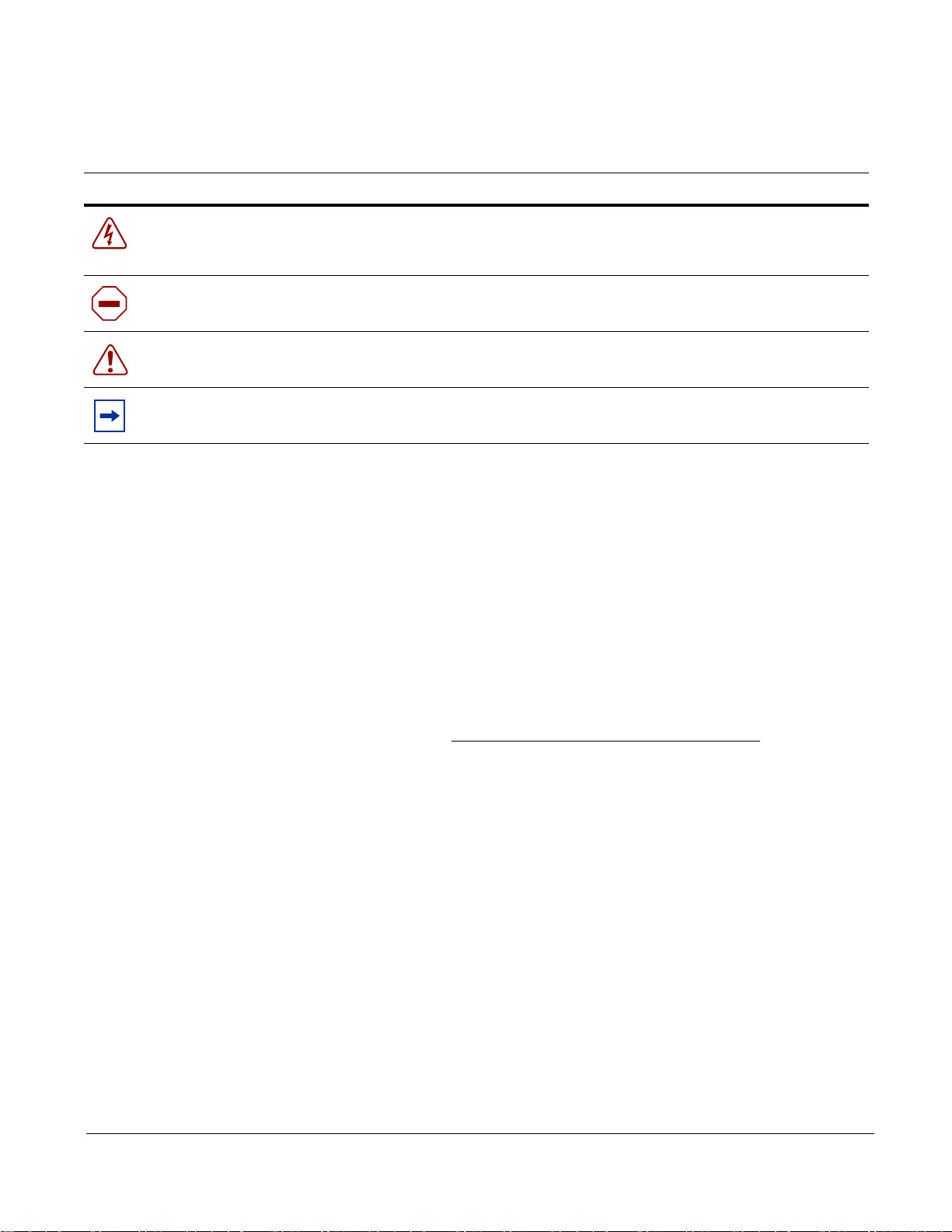
Information Symbols
Symbol Warning Description
Danger This symbol warns you that improper handling and installation could result in bodily injury.
Before you work on this equipment, be aware of electrical hazards, and take appropriate
safety precautions.
Caution This symbol informs you that improper handling and installation could result in equipment
damage or loss of data.
Warning This symbol informs you that improper handling could reduce your component or system
performance.
Note This symbol informs you of important operational information.
Related Documents
Additional P-Series documentation is available on the software CD that came with the appliance and in the
documentation section of the Force10 website, www.force10networks.com.
• P-Series Release Notes
Additional Resources
• Cox, Kerry and Gerg, Christopher. 2004. Managing Security with Snort and IDS Tools. Sebastopol,
California: O’reilly Media, Inc.
•Snort.org. http://www.snort.org/
8 About this Guide
Page 9
IDENTIFY
LAN 2
LAN 1
VGA
SERIAL
USB x2KEYBOARD
MOUSE
POWER
RJ-45 SERIAL
E0 & E1 IP ADDRESS
MANAGEMENT
PORTS
LEDs
POWER
DISPLAY
(E0)(E1)
MIRROR
PORT 1
(P1)
PORT 0
(P0)
PORT 0 (M0)
MIRROR
PORT 1 (M1)
HARD
DISK
fn9000007
AC POWER RECEPTACLE
MAIN POWER
fn9000009
01234567
SERIAL NUMBER
Chapter 1 Inst allation
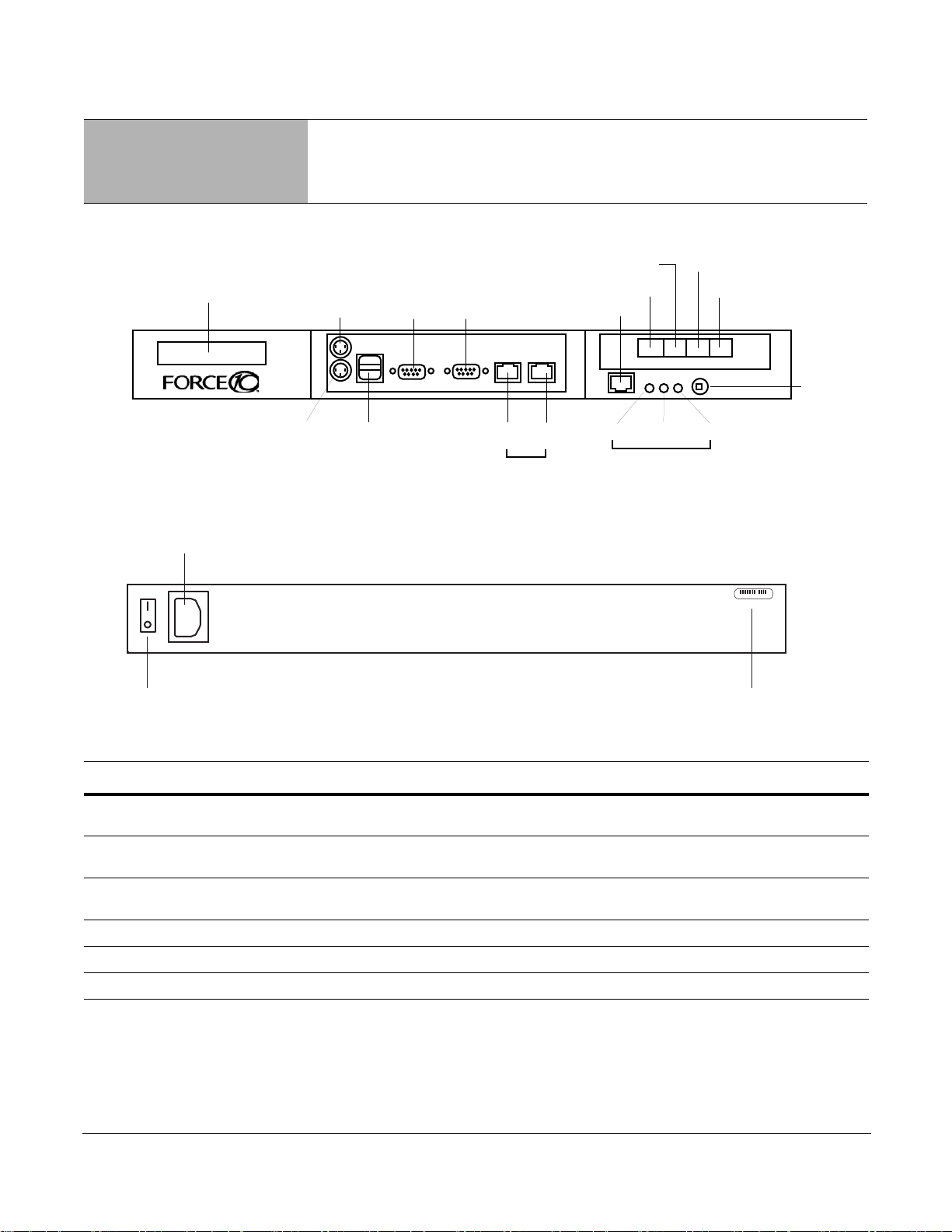
Figure 1 P-Series P10 Appliance (Front View)
Figure 2 P-Series P10 Appliance (Rear View)
Label Description
(LCD screen) The LCD screen displays the IP address of the appliance next to either “e0:” or “e1:”,
Port 1, Port 0 These two ports are sensing ports through which traffic is forwarded. They accept 10G
(unlabeled RJ-45 serial
port next to IDENTIFY)
IDENTIFY This LED is not used.
HDD This LED is blue when the hard disk is accessed.
PWR This LED is green when the power is on.
P-Series Installation and Operation Guide, version 2.3.1.2 9
which represent LAN ports 1 and 2, respectively.
XFP modules.
This port is not used.
Page 10

Label Description
FN00048A
(Power Button) This button turns the appliance on and off. Press and hold the button to turn off the
appliance.
(Laser Warning) This label in the bottom right corner of the appliance indicates that the appliance is a
Class 1 laser product that emits invisible laser radiation. This product complies with
CDRH, 21 CFR 1040.
System Specifications
The specifications in Table 1 apply to the P-Series P10 appliance, Force10 catalog number
PB-10GE-2P.
Table 1 System Specifications
Power AC Power Supply Power Consumption: 400W maximum, 260W nominal
Current: 3.6 A @ 120V, 2.0 A @ 240V
Voltage: 100-240V, 47-63Hz, 8A maximum input current
Heat Dissipation: 1360 BTU/hr maximum, 888 BTU/hr nominal
Battery 3V CR2032 coin cell
Physical Dimensions Height: 1.75 in
Width: 17.6 in
Depth: 15.5 in (1RU half depth)
Weight 20 lbs (9.07 kg)
Environmental Temperature Operating: 41° to 104°F (5° to 40°C)
Storage: -40° to 149°F (-40° to 65°C)
Relative humidity: 20-80% (non-condensing)
Altitude Operating:-50 to 10,000 ft (-16 to 3048 m)
Storage: -50 to 35,000 ft (-16 to 10,600 m)
Physical Connections
Note: Connections to the sensing, mirroring, and management ports require straig ht-throu gh CAT5 cables.
Warning: Do not hot-swap XFPs. If they are accident ally removed, turn off the appliance, replace the
XFPs, and then turn the appliance back on.
10 Installation
Page 11

Step Task
1 Review the system specifications and ensure that your operating and storage conditions meet the
stated requirements.
2 Connect the power cable, a keyboard, and a monitor to the appliance.
3 Connect the LAN 1 port on the appliance to the local area network where DHCP is available. If a
DHCP server is not available, an IP address can be assigned manually; see “Configuration” on
page 12.
4 Install XFPs in the ports that will be used.
5 Connect the sensing ports to the devices from which the appliance will receive traffic.
• Traffic originating from the device connected to Port 0 has Channel 0’s rules applied to it.
• Traffic originating from the device connected to Port 1 has Channel 1’s rules applied to it.
6 (Optional) Connect the mirroring ports to the devices that will receive mirrored traffic.
• Mirror Port 0 mirrors matched traffic from Channel 0.
• Mirror Port 1 mirrors matched traffic from Channel 1.
7 Connect the power cable to a power source, and switch on the main power on the back of the
appliance.
8 Press the power button on the front of the appliance to turn on the device.
P-Series Installation and Operation Guide, version 2.3.1.2 11
Page 12

Booting
During booting you can select the OS of your choice.
The management ports are configured for DHCP and probe for an IP address, gateway, and name server.
The IP address is displayed on the LCD screen.
When the appliance is powered up, all packets are forwarded between its ports by default until the
firmware and device drivers are loaded. Once they have been loaded, the DPI generates interrupts to the
host processor and offers the captured packets in the same way as a standard network interface card in
promiscuous mode.
Configuration
Once the appliance is booted:
Step Task
1 Log in as root with the password plogin.
2 Change the password, if desired, with the command passwd.
3 Set the clock for the appropriate timezone using the command tzsetup. This command calls a
graphical user interface that instructs you on how to select the appropriate timezone.
Security Check
The P10 is remotely accessible only via Secure Shell Daemon (SSHv1 or SSHv2). However, inspect the
configuration, and make sure it meets the security policy requirements of your network before deploying
the appliance.
Upgrading Software
Upgrading software requires a boot firmware (PROM) upgrade. This upgrade must be done during a
maintenance window. During this period, stop all traffic from flowing through the appliance, and
disconnect all cables from the XFPs.
Note: You must be logged in as root to upgrade software.
12 Installation
Page 13

Warning: Stop all traffic from flowing through the appliance, and disconnect all cables from the XFPs
before proceeding.
Step Task Command
1 Save earlier configuration files and firmware by
copying the directory /usr/local/pnic to the home
directory.
2 Create a new sub-directory in the home directory for
the upgrade package.
3 From the root directory, secure copy the file filename
from a server to the upgrade directory you created.
Note: In Unix, the tilde symbolizes the home directory,
and can be used in place of the absolute path to the
home directory. The upgrade file is a Unix tarball, the
file extension of which is .tar.gz.
4 Change directory to upgrade directory you created. cd upgrade_directory
5 Untar the file PTPS-P_MAIN. tar xvzf PTPS-P_MAIN
6 Change directory to SW. cd SW
7 Enter the command gmake erase followed by
gmake.
8 Enter the command gmake install. gmake install
9 Verify that the new software version is installed. pnic cardstatus
cp -Rf /usr/local/pnic/ /home
mkdir ~/upgrade_directory
scp username@server:absolute_path/
filename ~/upgrade_directory
gmake erase
gmake
Warning: The remainder of this procedure is for upgrading the boot firmware. The boot firmware
upgrade process takes up to 30 minutes and must not be interrupted
boot firmware must be reloaded via JTAG, which requires an RMA.
10 Enter the command pnic loadeproms to upgrade the
boot firmware. Answer “yes” to the confirmation
question.
Note: This process takes up to 30 minutes.
11 Reboot the appliance.
Note: Reboot the appliance only after pnic
loadeproms has successfully finished.
12 Log into the ap plia nc e an d en te r th e com m a nd pnic
cardstatus. Verify that there is an output for this
command. This indicates that the upgrade process has
been completed successfully.
Note: See Appendix A , on page 79 for an example
output for this command.
P-Series Installation and Operation Guide, version 2.3.1.2 13
pnic loadeproms
shutdown -r now
pnic cardstatus
. If the process is interrupted, the
Page 14

Step Task Command
13 Re-compile all rules firmware with the new compiler
located in the directory pnic-compiler.
14 Install pre-compiled firmware if needed. cd upgrade_directory/firmware
cd upgrade_directory/pnic-compiler
gmake
gmake install
14 Installation
Page 15

Chapter 2 Getting Started
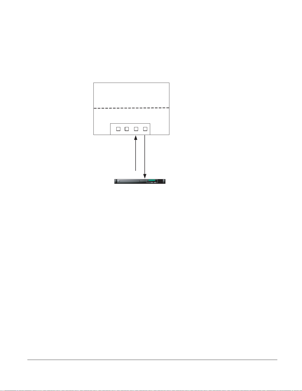
To begin inspecting and filtering traffic you must:
1. Select firmware and dynamic rules
2. Set capture/forward policies
3. Check for proper operation by generating traffic across the appliance.
Step Task
1 As root, enter the command pn
interface (GUI).
2 Enter the command m fr
3 Select Ma
The sample firmware and rules files are te sting example s only. Force 10 recommends
the sample firmware for production IDS/IPS use.
4 Select Edit Rules from
5 Uncomment the rule aler
symbol before the rule.
• Enter the command i to
• Navigate to the character using the arro w keys , an d de let e th e cha r act er.
6 Enter the command :wq to
7 Confirm to reload the Forward/Block settings.
8 Run a packet sniffer such as tcp
9 Generate some ICMP traffic to be exchanged between endpoi nts.
• End
those nodes passes through the appliance.
• For example, enter pi
the opposite end of the appliance.
nage Firmware from the Rule Management GUI, then select “null” firmware and confirm.
points are two network nodes on opposite sides of the appliance such that traffic between
om the GUI command line.
the Rule Management GUI.
ic gui from the Unix command line to invoke a graphical user
t on all icmp any any -> any any (msg:"@icmp";) by removing the #
enter insert mode.
exit the vi editor, and confirm your changes.
dump on the network interface associated with the appliance.
ng destaddress, where destaddress is the IP address of the endpoint on
not employing
10 If you are using tc
• This prints to standard output all of the packets captured by the DPI.
• If the appliance is operating correctly, you will see the ICMP packets.
pdump, enter the command tcpdump -i pnic0 -n from the Unix command line.
Returning to the Default Configuration
Return to the factory default settings using the command pnic resetconf. See the Command Line
Reference, on page 79.
P-Series Installation and Operation Guide, version 2.3.1.2 15
Page 16

16 Getting Started
Page 17

Chapter 3 Introduction
The P-Series P10 Intrusion Detection and Prevention System (IDS/IPS) appliance employs Dynamic
Parallel Inspection (DPI) technology. It uses a Multiple Instruction Single Data (MISD) massively parallel
processor that executes thousands of security policies or traffic capture operations on the same data stream
at the same time.
DPI synthesizes individual security policies and packet analysis algorithms and maps them directly into
silicon hardware "gates." Through this design it is able to deliver full packet inspection and protection at
line rate for 1-Gigabit and 10-Gigabit links whether the traffic load or security policy is 1% or 100%.
The policies can be derived from public domain signatures, or they can be completely user-defined. For
each policy, you can direct the DPI to:
• Capture packets for the host (capture is defined as both DMA to host and copying to the mirror port)
• Forward packets (with negligible delay)
• Block packets
As a result, the P10 can be used as both an IDS accelerator and a stateful content filter for IPS applications.
In an active configuration, it can be inserted inline into the network; this alleviates the need for a SPAN
port or tap and enables filtering applications. In passive configurations, it can merely listen to the network
via a mirroring port or tap.
Hardware Architecture Overview
The P10 is a 1-RU appliance provisioned with one DPI processing system, and has at minimum: an AMD
Dual Core Opteron 280 processor, a 400-GB hard drive, 8 GB of RAM.
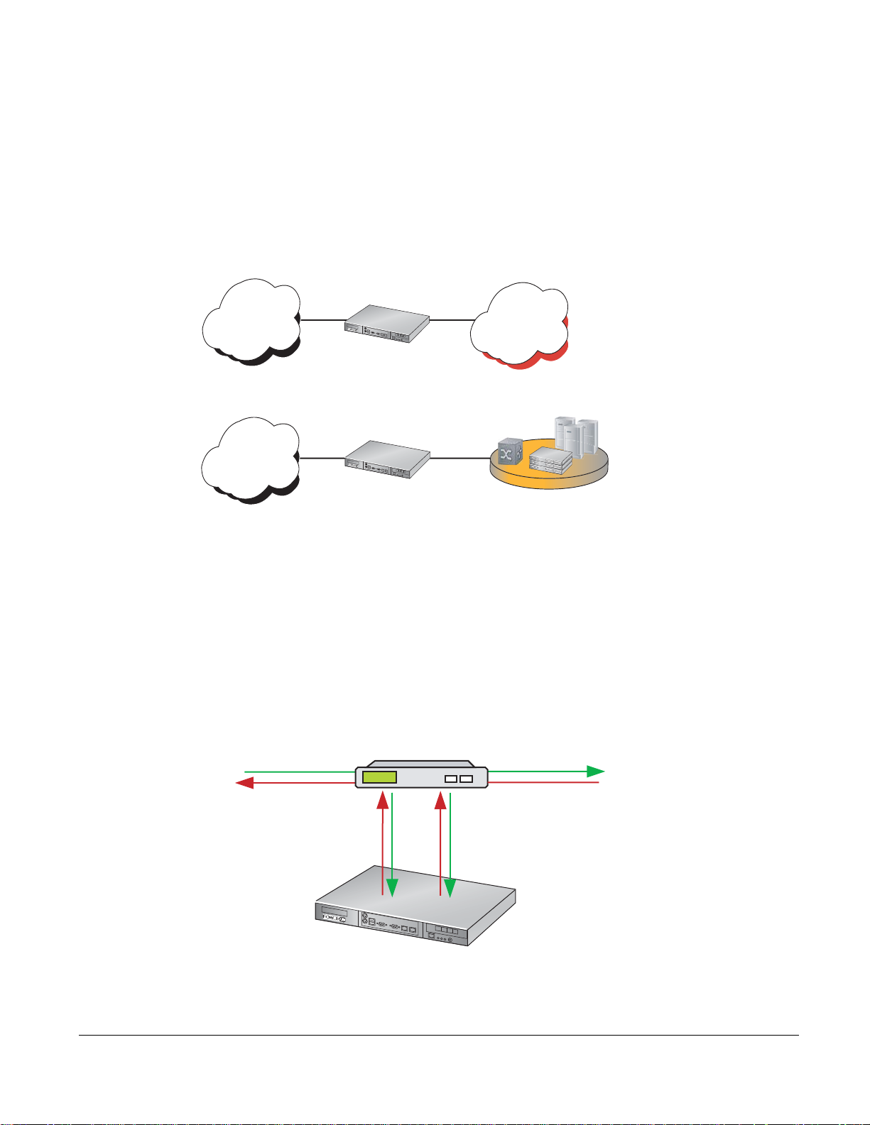
Figure 3 shows packet flow in the DPI, which is a two-port device. Packets are forwarded from the receive
side of the first port (Rx0) to the transmit side of the second port (Tx1). Likewise, Rx1 forwards packets to
Tx0 of the first port.
As the packets are being forwarded they are also processed in real time by two independent processing
channels, each with its own set of policies. If there is a match in a processing channel, the DPI can block
the packet, capture it, and send it to the host through the PCI-X bus. The two processing channels are
completely independent, and thus they can be used to process two asymmetric links, or both directions of a
full-duplex connection.
In addition to two sensing interfaces, the P10 includes two 1-Gigabit Ethernet mirroring ports. These ports
can copy and forward matched traffic to another device. It is also possible to disable the PCI-X DMA
capture, and let the matched traffic bypass the host entirely for applications in which host capture is not
desired.
P-Series Installation and Operation Guide, version 2.3.1.2 17
Page 18
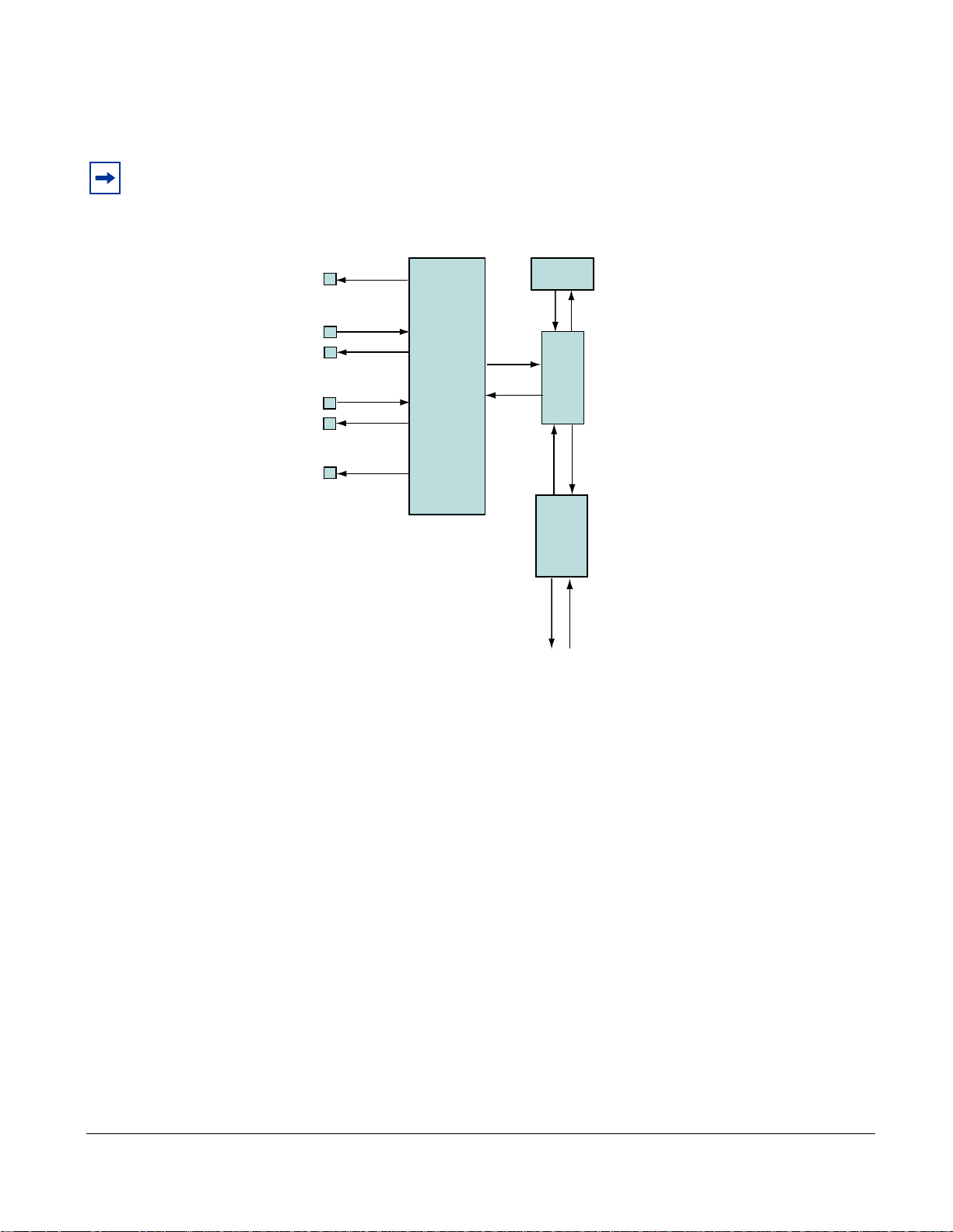
Figure 3 illustrates how all matched packets are copied and transmitted by mirror ports.
Forwarding Engine
Detection Engine
Packet Data
PCI-X Module
Packet Data
Device Access
Config Commands
Packet Data
State Table
Rx1
Tx1
Rx0
Tx0
Mirror 1
Mirror 0
Match Result
figindex 006
Note: Mirroring is automatically enabled when the mirroring port is connected to another network device.
Mirroring is not controlled through the CLI.
Figure 3
Logic Diagram of Traffic Flow in the P10 DPI
Types of Rules
Two types of rules can be uploaded to the FPGA:
atic rules : Static rules are compiled to become part of the firmware and are mapped directly into
• St
logic gates. Static rules can be set to capture/not capture and block/not block individually, but they
cannot be changed once they have been loaded into the FPGA.
• Dynam
ic rules: Dynamic rules are programmed at runtime in the DPI hardware registers and can be
configured without changing the firmware. These rules (like static rules) can be disabled/enabled
individually.
Sample Rules and Firmware
The P10 includes sample rules files in the pnic-compiler/rules directory. You can browse these files in
order to become more familiar with Snort syntax or creating rules files; you can also generate firmware
from these files at your discretion.
18 Introduction
Page 19

Firmware is a set of rules that has been transformed—using a compiler—from Snort syntax into a form
suitable for uploading to the FPGA. Two sets of sample rules files have been compiled into firmware and
are available to be uploaded to the FPGA using either of two firmware management methods (see “Rule
Management” on page 19). Table 2 desc ribes each sample rules file.
Table 2 Sample Rules Files
Rule Set Description
evasion.rules The rules in this file help detect attacks which are using strategic TCP segmentation to avoid
detection.
fw.rules This file contains rules written in Snort syntax for a firewall application (see “Writing Rules for a
Firewall Deployment” on page 77).
meta.rules The rules in this file report on flow information and provide compatibility with Snort.
null.rules This file contains no rules; the firmware created from these files are empty images that maximize
the dynamic rule capacity (see “Rules Capacity” on page 55).
sample.rules This file contains rules written in Snort syntax that were derived from publicly available IDS rules.
The firmware based on the sample rules files follow the naming convention described in “Selecting
Firmware with the GUI” on page 30.
Note: Force 10 recommends not using the sample firmware for production IDS/IPS use. The sample
firmware requires considerable site-specific customization in order to be effective; they are included only
for you to become more familiar with the functionality of the appliance.
Rule Management
The P-Series software provides three methods by which you can manage the rules and functionality of the
appliance:
• Graphical User Interface: The graphical user interface (GUI) is a menu-based method for managing
the appliance.
• Web-based GUI: Manage the appliance and graphically plot performance online.
• Command Line Interface: The command line interface (CLI) uses a script called pnic through which
you can manually perform the same management tasks as the GUI by entering commands at the
command prompt.
Force10 recommends using the GUI or web-based GUI if no programmatic interface is required.
Deploying the P-Series
The flexible architecture of the P-Series lends itself to various deployments.
P-Series Installation and Operation Guide, version 2.3.1.2 19
Page 20
Inline Deployment
p
P-Series P10
p
Use the P-Series for inline traffic inspection in IPS or firewall applications at 10-Gigabit line rate
(Figure 4).
• For IPS deployment, no special configuration is needed;
the P-Series is in inline IPS mode by default.
• For a firewall deployment, enable drop mode (see Command Line Reference on page 79).
Figure 4
P-Series Inline Deployment
Internet
Campus Core/
Backbone
10-Gigabit
10-Gigabit
P-Series P10
PB-10GE-2P
10Gig
10Gig
Data Center
PB-10GE-2P
P-Series P10
10-Gigabit
10-Gigabit
LAN Core
Data Center
fn90029m
Fail-safe Deployment
The P-Series hardware is fail-safe. In the event of a software exception or reboot, the card continues to
function as it did before the event. In the event of a power failure, the hardware stops functioning, and
traffic is dropped. When the appliance powers up again, all the traffic is allowed by default, and the card
functions as before. Use an optical bypass switch in an inline deployment so that traffic continues to flow
in the event of a power failure, as shown in Figure 5.
Figure 5
Fail-safe Behavior with Optical Bypass
10-Gigabit
Optical Bypass
10-Gigabit
P0
20 Introduction
P1
fn90030m
Page 21
Highly-available Deployment
Optical Bypass
10-Gigabit
P0
P1
P-Series P10
10-Gigabit
P0
P1
fn90031mp
Network Tap
P-Series P10
fn90032mp
P0 P1
10-Gigabit
10-Gigabit
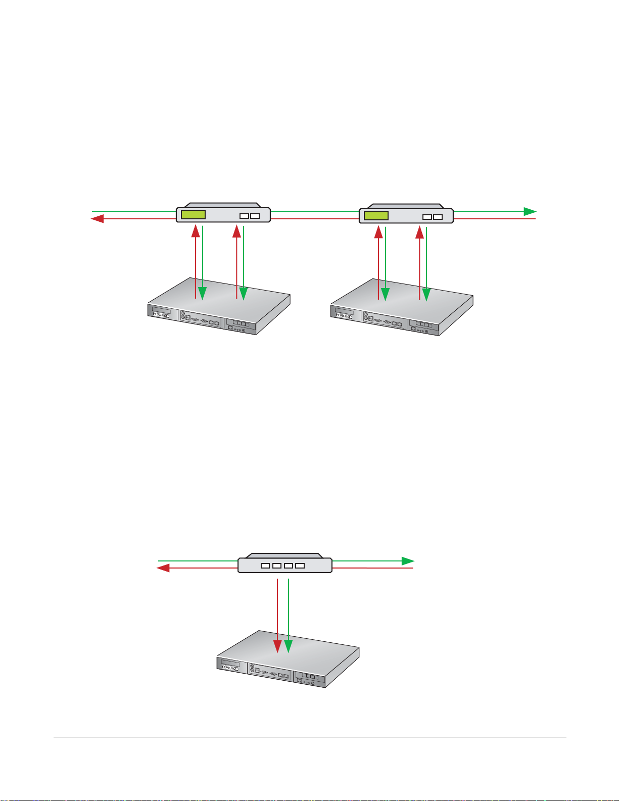
Use optical bypass switches with the P-Series for a highly-available, redundant deployment, as shown in
Figure 6. Both the appliances have the same configuration so that in the event of a power failure on one
device, the other continues to operate, and the detection engine remains intact. In the event that both
devices experience a power failure, the traffic continues to flow through the bypass switches.
Figure 6
Highly-available Redundant Deployment
Passive Deployment
Enable passive mode (see Command Line Reference on page 79) with fiber taps in line for IDS
deployments.
• Send traffic from one side of the tap to port P0 and traf
Figure 7.
• Aggregate traffic from both sides of the link to one port, as show
• Aggregate traffic from both sides of the link to one port using a SPAN port, as shown in Figure 9.
fic from the other side to port P1, as shown in
n in Figure 8.
P-Series Installation and Operation Guide, version 2.3.1.2 21
Figure 7
Passive Deployment using a Network Tap
Page 22
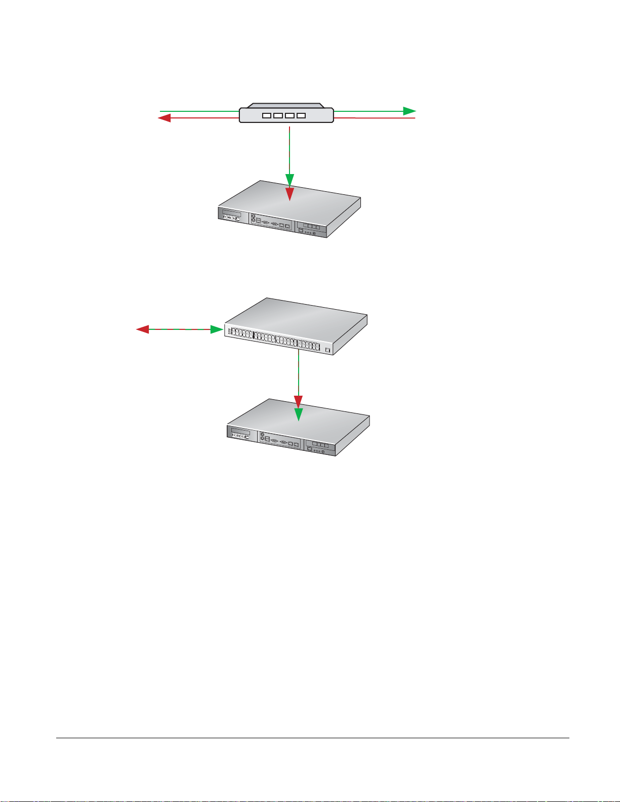
Figure 8
Network Tap
P-Series P10
fn90033mp
P0
10-Gigabit
10-Gigabit
Network Switch with SPAN port
P-Series P10
fn90034mp
P0
Port to Monitor
10-Gigabit
SPAN Port
Passive Deployment with Aggregation using a Network Tap
Figure 9
Passive Deployment with Aggregation using a SPAN port
Capturing Matched Traffic
P-Series supports capturing matched traffic for analysis.
22 Introduction
Page 23
Capturing to a Host CPU
fn90035mp
p
Captured traffic can be sent to a host CPU through a libpcap library interface, where it can be made
available to applications for analysis. A typical implementation provides IDS/Snort acceleration because
of the hardware assist.
Figure 10 Capturing Matched Traffic via the libpcap Interface
PB-10GE-2P
tcpdum p Snort Cust om app
libpcap
SW
Matched Traffic
HW
M1 P1 P0 M0
Traffic to
monitor
Use the P-Series in an integrated security monitoring solution through the management port. The P-Series
comes with support for Sguil NSM (see Network Security Monitoring on page 43).
Figure 11 Creating a Network Monitoring Solution with the P-Series
PB-10GE-2P
Cus tom app
libpcap
SW
Matched Traffic
HW
M1 P1 P0 M0
Traffic to
monitor
Mgmt
Port
Custom
security
monitoring
application
fn90036m
P-Series Installation and Operation Guide, version 2.3.1.2 23
Page 24
Mirroring to Another Device
Mirror captured traffic out of the 1-Gigabit mirroring ports to use the P-Series as an IDS accelerator or as
part of an integrated security monitoring solution.
Figure 12
Creating an IDS Accelerator with the P-Series
PB-10GE-2P
HW
M1 P1 P0 M0
Traffic to Monitor
Matched Traffic
1-Gigabit/IDS Security
Monitoring Application
fn90037mp
24 Introduction
Page 25

Chapter 4 Graphical User Interface
The GUI can be used to:
• Start and stop the DPI
• Load firmware
• Compile and load dynamic rules
• Manage the runtime parameters
• Manage the capture/forward policies for rules
Note: Using the GUI requires the super user privilege.
To invoke the GUI:
Step Task
Invoke the GUI by entering the command pnic gui.
1
Note: The OS environment variables are set such that the pnic gui command can be executed from any
path.
Runtime statistics are displayed after the
display appears as shown in Figure 13. If firmware is loaded, the display appears as in Figure 19.
pnic gui command is executed. If the FPGA is not loaded, the
P-Series Installation and Operation Guide, version 2.3.1.2 25
Page 26
GUI Commands
fn9000010
N/A/1 FlowTimeout=16 Packets/flow=0 Truncation=0 Irq period=5ms
CPU(s): 0.0% user, 0.0% nice, 0.0% system, 0.0% interrupt, 100% idle
From the Runtime Statistics display, you can enter commands to control the DPI (see Table 3, or enter the
h command from the GUI command line).
Figure 13
Runtime Statistics - FPGA Unloaded
Note: GUI commands that require a subsequent value entry have the current value displayed in
parentheses at the prompt.
Table 3 GUI Commands
Command Description
a Establishes the IRQ period (measured in milliseconds), which moderates DPI access to the PCI-X
bus. Va lid values are 1 to 255, where 1 is no throttling, and 255 is maximum throttling.
c This command is not supported.
d Brings the OS network interface down and disables matching.
f Establishes the maximum number of p acket s to be captured for each flo w (Packet s/Flow). A valu e of
0 specifies all packets.
h Displays help information about the commands.
i Establishes the display refresh interval (measured in seconds).
m Invokes a dialog menu through which dynamic rules ca n be defined, cap ture /forw ar ding p olicies can
be set for each individual rule, and the firmware can be selected and loaded.(see Figure 14).
q Exits the graphical user interface.
r Reset all the OS counters.
s Starts or restarts the drivers and reloads the firmware.
t Establishes the number of seconds after which a flow is considered expired (Flow Timeout).
26 Graphical User Interface
Page 27
fn9000011
PNIC0 Not Active
Table 3 GUI Commands
Command Description
u Brings the OS network interface up and enables matching. This is similar to the command s, but it
does not load/reload the driver. It is only valid after the command s has been executed.
x Toggles the direct memory access (DMA) off and on to enable or disable capturing to the host,
respectively.
z Disables the DMA and brings the interface down, in succession. This is equivalent to issuing the
commands pnic down and pnic off, in succession.
Note: Commands 1, 2, 3, 4, and 5 are for engineering use only. If you enter a command 1 through 5 by
mistake, enter 0 to return to the runtime statistics screen.
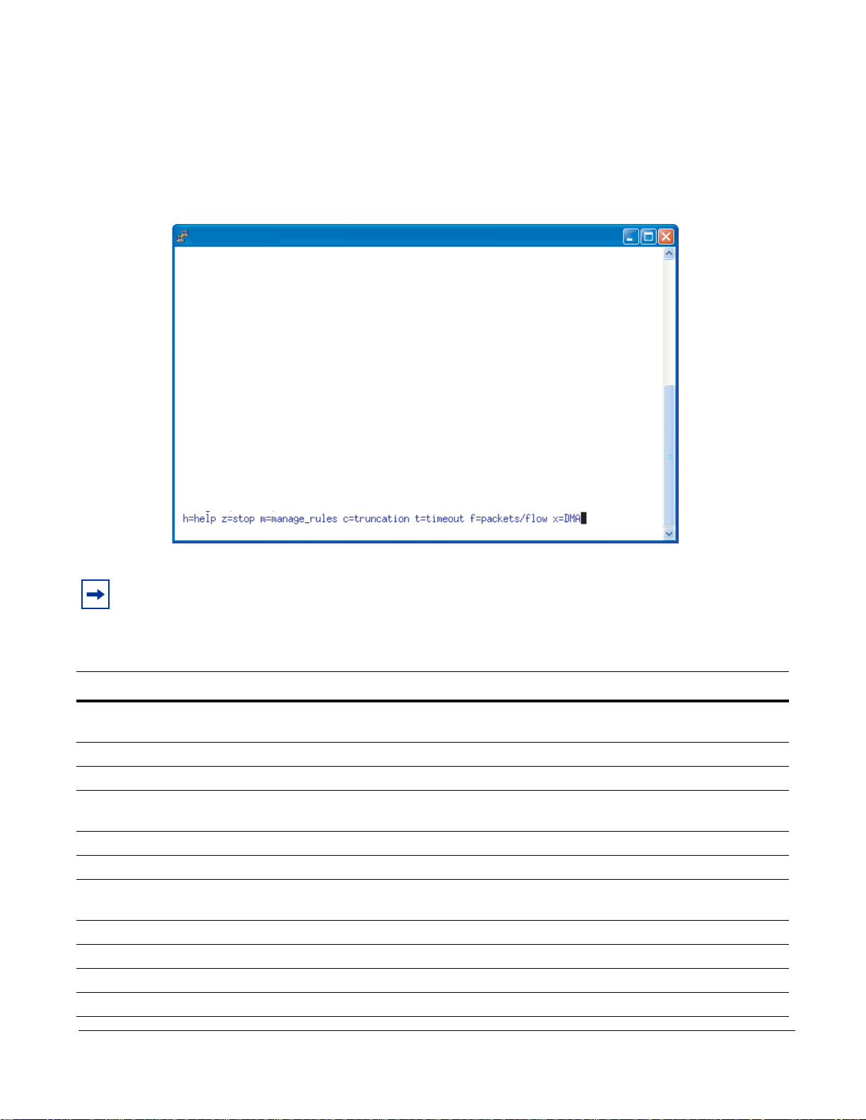
Managing Rules, Policies, and Firmware
Enter the m command from the GUI command line (see “GUI Commands” on page 26) to invoke a menu
that enables you to manage dynamic rules, capture/forward policies, and firmware. Three options are
available; they are shown in Figure 14 and described in Table 4.
Figure 14 Rule Management GUI
P-Series Installation and Operation Guide, version 2.3.1.2 27
Page 28

Table 4 Managing Rules Using the GUI
Option Description
Edit Rules This option invokes the vi editor on the file rules.custom in the /user/local/pnic/0
directory (see “Editing Dynamic Rules with the GUI” on page 28).
• You can add, delete, or modify dynamic rules for either of the processing
channels (see Appendix D , on page 125 for informa tion on vi).
• The rules are automatically compiled and loaded into the appliance; you are
prompted to confirm these actions.
Manage Rules This option instructs the DPI on handling matching packets.
• It displays a list of all the rules contai ned in the FPGA and the policy setting for
each.
• There are four policies available, and they are described in Table 5.
• Rules configured to ignore a packet—that is, the policy setting is permit or
deny—take precedence over rules that have a policy setting of alert or divert.
Therefore, a permit or deny rule disables the capturing for all other rules that
match the same packet.
• To modify policy settings, see “Managing Capture/Forward Policies with the
GUI” on page 29.
Note: The Capture toggle is not used. Capture/forward settings can only be
modified through the graphical user inte rfa c e.
Manage Firmware It displays the firmware files in /usr/local/pnic/firmware and allows you to select
one to be uploaded to the FPGA. Selecting firmware restarts and reloads the
FPGA.
To manage firmware, see “Selecting Firmware with the GUI” on page 30.
Table 5 describes the four possible combinations of capture/forward policies.
Table 5 Capture/Forward Policies
Policy Capture Forward
Permit
Deny
Alert
Divert
33
3
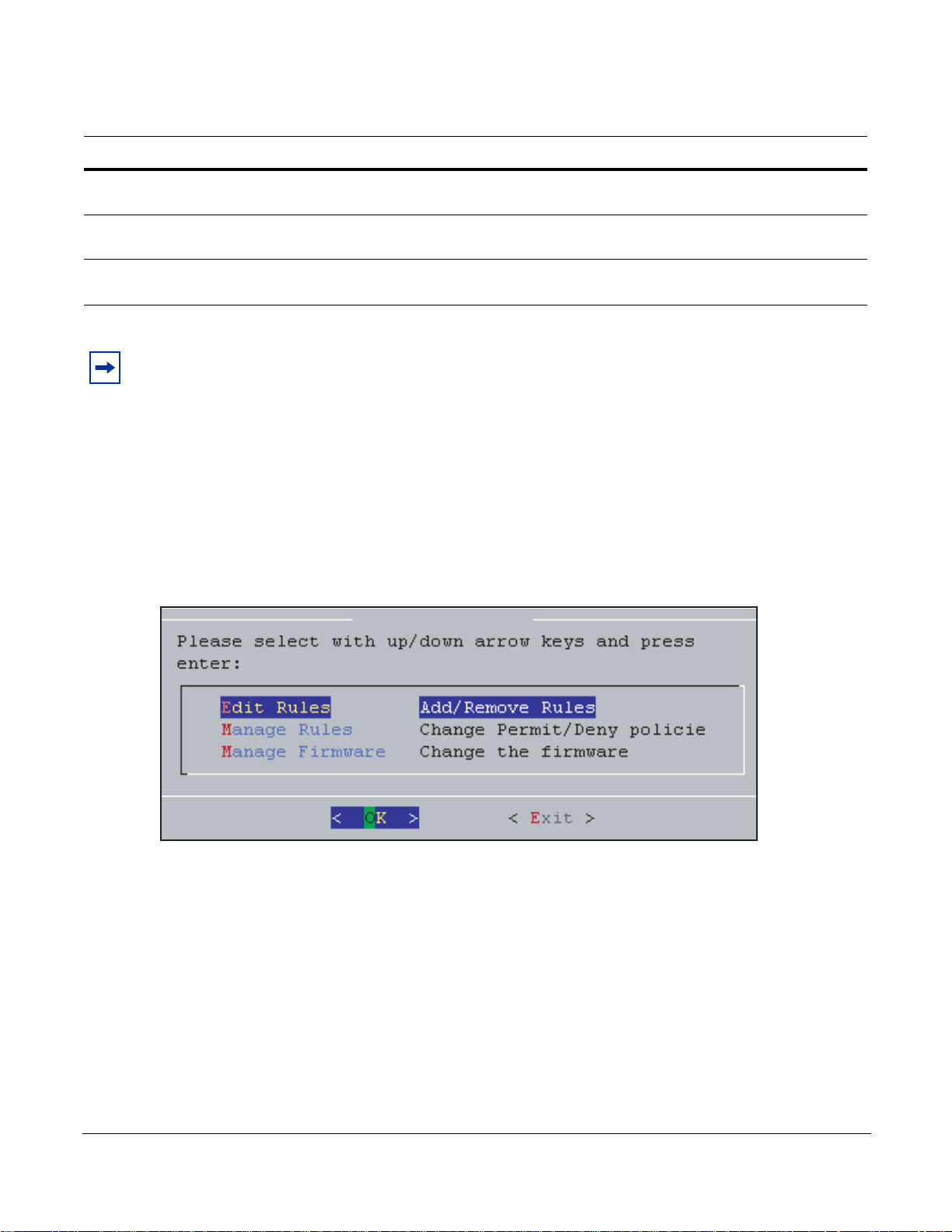
Editing Dynamic Rules with the GUI
Dynamic rules are stored in the file rules.custom in the /usr/local/pnic/0 directory. The GUI provides a
quick way to access and modify these rules by invoking the vi editor on this file.
3
28 Graphical User Interface
Page 29
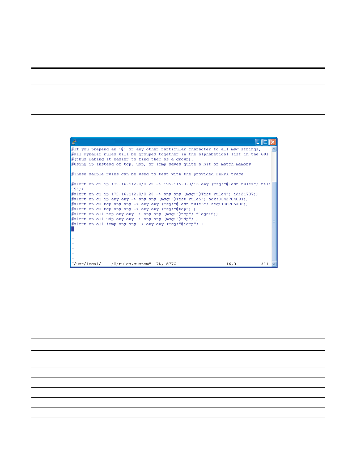
To modify dynamic rules:
fn90000012
pnic
Step Task
Enter the m command from the GUI command line (see “GUI Commands” on page 26) to access the
1
main rule management GUI (see Figure 14).
2Select Edit Rules to invoke the vi editor (see Figure 15).
3 Add, delete, alter, or uncomment rules using vi commands (see Appendix D , on p age 125).
4 You are prompted to confirm your changes upon exiting the editor.
Figure 15 Editing Dynamic Rules in vi
Managing Capture/Forward Policies with the GUI
Upon compiling static and dynamic rules, default capture/forward policies are assigned to each rule.
To change capture/forward policies:
Step Task
Enter the m command from the GUI command line (see “GUI Commands” on p a ge 26) to access the rule
1
management GUI (see Figure 14).
2Select Manage Rules to access the policy management menu (see Figure 16).
3 Use the arrow keys to highlight a rule and the Select option, and press the Enter key.
4Select alert, permit, divert or deny, based on the descriptions in Table 5 (also see Figure 17).
5 Exit the menu by selecting Done, and repeat Steps 3 through 5 for other rules, if desired.
6Select Done; you are prompted to confirm your changes.
P-Series Installation and Operation Guide, version 2.3.1.2 29
Page 30
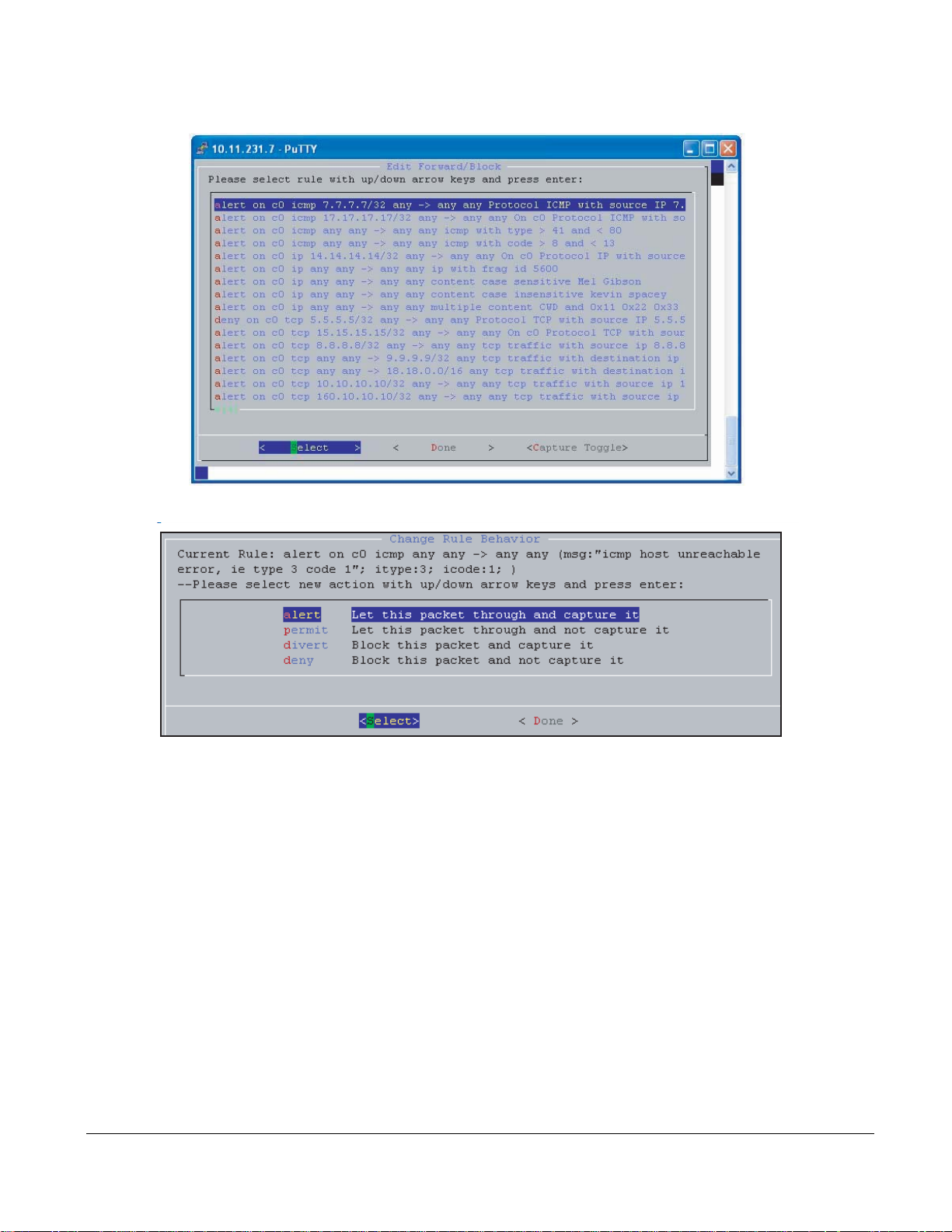
Figure 16
fn9000013
fn9000014
Managing Capture/Forward Policies GUI
Figure 17
Capture/Forward Policies GUI
Selecting Firmware with the GUI
Firmware is a set of rules that has been transformed—using a compiler—from Snort syntax into a form
suitable for uploading to the FPGA.
30 Graphical User Interface
Page 31

To select firmware:
fn9000015
Step Task
Enter the m command from the GUI command line (see “GUI Commands” on p age 26) to access the main
1
rule management GUI.
2 Select Manage Firmware (see Figure 18).
3 Use the arrow keys to highlight the desired firmware and the Select option, and press the Enter key. See
“Firmware Filename Description” on page 62 for information on identifying firmware by their filenames.
4 Confirm your selection, and exit the GUI.
Figure 18 Manage Firmware GUI
Runtime Statistics
Runtime statistics are displayed when firmware is uploaded, and traffic is flowing across the appliance.
The GUI presents two views of traffic statistics. The default view shows the total statistics for Channel 0
and 1, as shown in Figure 19. Enter the command
as a sum, as shown in Figure 20. Use the command
• The first line shows the device number, type of device, firmware ID, and version number.
• The second line shows the status of the Ethernet inte
values of Flow Timeout, Packets/Flow, and IRQ Period. These parameters can be adjusted using the
GUI commands described in Table 3.
p to view traffic statistics for both channels separately or
p to toggle between the two views.
rface and direct memory access (DMA), and the
P-Series Installation and Operation Guide, version 2.3.1.2 31
Page 32

The remaining lines report the cumulative number of events and the rate of those events. A description of
CPU(s): 0.0% user, 0.0% system, 0.0% nice, 100.0% idle
Dev: 8002 - Type: PNIC-0 - FirmwareID: 64 - Ver:2.6 - DefaultDrop: disabled
pnic0 UP Capture=on FlowTimeout=16 Packets/flow=0 Truncation=0 Irq period=1ms
HW Interfaces CH0 Top Rate/s CH1 Top Rate/s
Total Packets 0 0 0 0
TCP Packets 0 0 0 0
UDP Packets 0 0 0 0
ICMP Packets 0 0 0 0
Other Packets 0 0 0 0
Capture Packets 0 0 0 0
Total Flows 0 0 0 0
Delayed Pkts 0 0 0 0
Stateful Pkts 0 0 0 0
Blocked Packets 0 0 0 0
OS Interface pnic0:0 Rate/s pnic0:1 Rate/s
Rx (Packets) 2838226 0 2838042 0
Rx (Bytes) 1408250941 0 1407263719 0
Rx (Bits) 2676072936 0 2668175160 0
Errors 0 0 0 0
Truncated (Pkts) 0 0 0 0
h=help z=stop m=manage_rules c=truncation t=timeout f=packets/flow x=DMA
CPU(s): 0.0% user, 0.0% system, 0.0% nice, 100.0% idle
Dev: 8002 - Type: PNIC-0 - FirmwareID: 64 - Ver:2.6 - DefaultDrop: disabled
pnic0 UP Capture=on FlowTimeout=16 Packets/flow=0 Truncation=0 Irq period=1ms
HW Interfaces CH0 Top Rate/s CH1 Top Rate/s
Total Packets 0 0 0 0
TCP Packets 0 0 0 0
UDP Packets 0 0 0 0
ICMP Packets 0 0 0 0
Other Packets 0 0 0 0
Capture Packets 0 0 0 0
Total Flows 0 0 0 0
Delayed Pkts 0 0 0 0
Stateful Pkts 0 0 0 0
Blocked Packets 0 0 0 0
OS Interface pnic0 Rate/s
Rx (Packets) 5676268 0
Rx (Bytes) 2815514660 0
Rx (Bits) 1049280800 0
Errors 0 0
Truncated (Packets) 0 0
h=help z=stop m=manage_rules c=truncation t=timeout f=packets/flow x=DMA
each line is given in Table 6.
Figure 19
Figure 20
Runtime Statistics for Channel 0 and 1—FPGA Loaded
Cumulative Runtime Statistics for Channels 0 and 1—FPGA Loaded
32 Graphical User Interface
Page 33

Table 6 Runtime Statistics Description
Statistic Description
Total Packets Shows the number of packets received by the ports. This is a Layer 1 statistic and is
independent of whether the OS interface is up or down.
TCP/UDP/ICMP/Other Reports the type of packets received during matching. Other includes all non-IP types
and all IP types other than TCP, UDP, and ICMP.
Capture Packets Counts the total number of packets matched and captured by some policy.
Total Flows Reports the number of new flows started according to the flow policies.
Stateful Packets Reports the number of packets matched because of a stateful policy. The mathematical
difference between this counter and th e Captured Packets counter is the number of
packets captured by stateless policies.
Blocked Packets Reports the number of packets blocked because of some policy, except that packets
blocked by default are not counted.
Rx Packets/Bytes/Bits Tracks data received by the OS. Any difference between the values in this line and those
in the Captured Packets line is due to buffering and/or packet loss; packet loss is due to
high contention on the CPU.
Errors Reports the number of anomalous receive conditions the driver encounters.
Truncated Packets This feature is not supported.
Delayed Packets Reports the number of packets that were stored in the temporary buffer in hardware.
Reloading Firmware
During firmware reloading, all packets flow regardless of capture/forward policies, as the policies cannot
be enforced during system initialization. This "open" state during configuration state transition ensures that
there is no interruption of service when the DPI is updated.
If the OS crashes or is halted, the device drivers are rendered inactive, but the card continues to operate
independently and block/forward policies are still enforced. This behavior applies even when the device
drivers are re-installed during a reboot.
P-Series Installation and Operation Guide, version 2.3.1.2 33
Page 34

34 Graphical User Interface
Page 35

Chapter 5 Web-based Management
You can manage and monitor the P-Series on the web using the Force10 Networks P-Series Node Manager.
Note: The web-based GUI is supported on Linux only, which is the default OS, and requires software
version 2.3.0.0 or newer.
Launching the P-Series Node Manager
Note: The Web-based GUI is best viewed with a minimum screen resolution of 1280x800. You must also
have Java Run Time Environment (JRE) installed with the “Use JRE X.Y.Z for <applet>” option enabled
under Tool --> Internet Options --> Advanced tab when using either Internet Explorer 6 or 7.
To launch the P-Series Node Manager:
Step Task
Enter the command
1
Appendix A , on page 79).
Lauch the P-Series Node Manager in a web brower by ent er ing
2
shown in Figure 21.
Login using the username and password configured on your P-Series appliance.
3
pnic web-gui-start to enable the secure HTTP service on the P-Series (see
https://ipaddress in the address bar, as
P-Series Installation and Operation Guide, version 2.3.1.2 35
Page 36

Note: Stop the secure HTTP service using the comma nd pnic web-gui-stop (see Appendix A , on page
79).
Figure 21 Lauching the P-Series Node Manager
36 Web-based Management
Page 37

Web-browser Security Certificates
The P-Series Node Manager client and the server communicate via HTTPs. All transactions are encrypted,
and thus protected, by the SSL protocol. The SSL certificate is a self-signed certificate that is not signed by
a trusted Certificate Authority (CA). While trying to launch the P -Series Node Manager, your web browser
might display an alert indicating that the security certificate was not issued by trusted CA or a similar
warning (Figure 22). You are safe to use the application without security risks.
Figure 22 Web-browser Security Certificate Alert
Managing the P-Series using Node Manager
P-Series Node Manager has four major management capabilities:
• Monitoring System Performance on page 38
• Managing Firmware Images on page 39
• Managing the Network Interface Card on page 39
• Managing Policies on page 41
P-Series Installation and Operation Guide, version 2.3.1.2 37
Page 38

Monitoring System Performance
Monitor system performance from the Home panel (Figure 23). The Home panel is displayed after logging
into Node Manager. It displays basic system information, card, interface, and resource information, as w ell
as CPU and memory usage over time.
Figure 23 P-Series Node Manager: Home Panel
38 Web-based Management
Page 39

Managing Firmware Images
Manage the software image from the Image Management panel (Figure 24). The Image Management panel
provides options for compiling and deleting an image. It displays a list of available images along with the
currently applied image and its details.
Figure 24 P-Series Node Manager: Image Managment Panel
Managing the Network Interface Card
Manage the network interface card from the Card Management panel. The Card Management panel
displays hardware and software counters for Channel 0 (pnic 0:0) and Chan nel 1 (pnic 0:1). Counters are
displayed in absolute value and in graphical or tabular format, as shown in Figure 25.
P-Series Installation and Operation Guide, version 2.3.1.2 39
Page 40

Figure 25 P-Series Node Manager: Card Management Panel
40 Web-based Management
Page 41

Managing Policies
Manage policies from the Policy Management panel (Figure 26). The Policy Manag ement panel provides
you with a list of available static and dynamic rules available for the currently running image. It also has
the provision for adding, modifying, and deleting dynamic rules.
P-Series Installation and Operation Guide, version 2.3.1.2 41
Page 42

Figure 26 P-Series Node Manager: Policy Managment Panel
42 Web-based Management
Page 43

nt
P-Series Sensors
fn90025mp
Chapter 6 Network Security Monitoring
A key aspect of network security deployment is the ability to monitor the network for security events,
analyze them, and perform counter measures. To that end, the P-Series supports Sguil, an open source
network security monitoring and reporting system that provides the ability to:
• collect, monitor, and correlate security events/alerts in the network
• analyze security events based on context
• categorize and escalate events for intrusion response decisions
The Sguil solution consists of the
• Sensors—Sensors are the
• Databas
• Client—The client
• Server—T
Figure 27
following components (Figure 27):
systems actually monitoring network traffic and collecting data. Sensors
perform packet captures of network traffic in addition to running Snort in alert mode.
e—The database holds the alert and session data that the sensors collect.
is the interface to the Sguil server.
he Sguil server maintains connections to the sensors, clients, and database.
Sguil Architecture
Sguil Server
Security Alert Information
Sguil Clie
P-Series Installation and Operation Guide, version 2.3.1.2 43
Page 44

Installing the Sguil System
To employ Sguil you must:
1. Install the sensor. See page 44.
2. Install the server. See page 44.
3. Install the client. See page 45.
Note: You can download the server and client Sguil components directly from the Sguil website at http://
sguil.sourceforge.net/index.html. The solution uses a number of components which must be installed. For
your convenience, a simplified install package is provided on the Force10 Networks support website;
please see the instructions in the remainder of this chapter.
Installing the Sguil Sensor
P-Series appliances running version 2.3.0.0 or newer are already capable of operating as a Sguil sensor.
Installing the Sguil Server
The Sguil server package installs the Mysql server and Sguild server packages.
Hardware and Software Requirements
Force10 recommends using a server that has at least 2 GB of RAM, a 3.0 GHz processor, and 150 GB hard
disk with a RAID5 array for speed and reliability.
Sguil runs on a variety of *BSD and Linux-based systems. Force10 has tested compatibility with and
recommends using:
• CentOs 5 64 bit Linux version 2.6.18-8.1.14.el5
• CentOs 5 32 bit Linux version 2.6.18-8.1.14.el5, or
• FreeBSD-6.2-<release>
Note: Red Hat Enterprise Linux (RHEL) might also be compatible but has not been tested.
To install the server:
Step Task Command
1Copy sguil-server-<version>.tar.gz to the server in which it will be installed.
2 From the dir ec to ry wh er e th e server package is stored,
untar the Sguil server package.
tar -zxvf sguil-server-<version>.tar.gz
3 Change to Bash shell.
44 Network Security Monitoring
bash
Page 45

Step Task Command
4 Source the server configuration file. The default
parameters in this file may be changed.
5 Compile and build the Sguil server package. Use the
logging option to collect debugging information during
compilation and redirect standard output and errors to a
log file.
6 Install the Sguil server package.
7 (OPTIONAL) Set the debug flag to 1 in sguild.conf before executing Startserver .sh to display Sguil server
debug messages
source Configure-Inputs.sh
gmake [> build.log 2>&1]
gmake install
Uninstalling the Sguil Server
To uninstall the server:
Step Task Command
1 Stop the Sguil and MySQL servers, if they are running.
2 From the dir ec to ry in whic h th e sev er package was
installed, source the Sguil server configuration file.
3 Uninstall the Sguil server. Use the logging option to
collect debugging information during uninstallation and
redirect standard output and errors to a log file.
source Configure-Inputs.sh
gmake uninstall [> uninstall.log 2>&1]
Installing the Sguil Client
You must have the following software installed in your PC before installing the Sguil client:
• ActiveTcl, Force10 recommends ActiveTcl8.4.14 which includes Wish
•WinZip
•Wireshark
•Wish
• Download the OpenSSL TCL extension TLS package to the client and extract the contents to the lib
directory of the TCL installation. Typically the TCL installation directory is c:\program files\tcl.
To install the client:
Step Task
1Copy sguil-client-<version>.tar.gz to the PC on which it will be installed.
2 Extract the tar file.
P-Series Installation and Operation Guide, version 2.3.1.2 45
Page 46

Step Task
# PATH to tls lib if needed (tcl can usually find this by default)
#set TLS_PATH /usr/lib/tls1.4/libtls1.4.so
# win32 example
set TLS_PATH "c:/progra~1/Tcl/lib/tls1.4.1/tls14.dll"
3 Configure the following parameters in the file sguil.conf:
• Enable (1) or disable (0) the debug option
• Set the browser path.
• Set the Wireshark application path.
• Set the TLS library path, as shown in Figure 28.
• Set priority levels of the alert window.
Figure 28 Setting the TLS Library Path
Installation Files
Table 7 lists the files and directories created during installation that are relevant to running the Sguil
system.
Table 7 Sguil Files and Directories
File Location
Sensor
sensor installation directory /usr/local/pnic-mgmt-lib/sguil-sensor
sensor configuration files <install_dir>/nsm/sguil/etc
snort.conf <install_dir>/nsm/sguil/etc/
log files <install_dir>/nsm/sguil/logs
rules files <install_dir>/nsm/sguil/rules
Snort logs /var/log/Snort
Packet logs /var/log/Sensor/LogPackets
Server
server installation directory /usr/local/sguil-server
sguild.conf <install_dir>/nsm/sguil/etc
log files <install_dir>/nsm/sguil/logs
46 Network Security Monitoring
Page 47

Running the Sguil System
root@# pnic sguil-sensor-start
Enter the IP address of the Sguil-Server:192.16.130.246
***********************************************
INTERFACE NAME : pnic0
SGUIL-SERVER IP-ADDRESS : 192.16.130.246
***********************************************
To start Sguil-sensor with the above configuration
Select "Ok"
1) Ok
2) Exit
#? 1
Starting sguil sensor processes...
Info: <InstallDir>/sguil-pids/snort_log-localhost.pid does not exist.
Checking for old process with ps.
No old processes found.
Starting new process anyway...
LogPackets started successfully.
Checking disk space (limited to 90%)...
Current Disk Use: 26%
Done.
Barnyard started successfully.
Snort started successfully.
Sancp started successfully.
Pcap Agent started successfully.
Sancp Agent started successfully.
Snort Agent started successfully.
Sguil-sensor has started successfully.
root@# pnic sguil-sensor-stop
Do you really want to stop the Sguil-sensor application (y/n)? y
LogPackets stopped successfully.
Stopped Pcap Agent successfully
Stopped Sancp Agent successfully
Stopped Snort Agent successfully
Stopped Barnyard successfully
Stopped Snort successfully
Stopped Sancp successfully
Stopped tail of snort.stats successfully
Sguil-sensor application has been stopped.
Running the Sguil Sensor
Start the Sguil sensor using the command pnic sguil-sensor-start. Specify the IP address of the Sguil
server, and confirm the action, as shown in Figure 29.
Figure 29
Starting the Sguil Sensor
Stop the Sguil sensor using the command pnic sguil-sensor-stop, as shown in Figure 30.
Figure 30
P-Series Installation and Operation Guide, version 2.3.1.2 47
Writing New Rules
• All rules files are stored in the installation sub-directory .../nsm/sguil/rules.
Stopping the Sguil Sensor
Page 48

• The rule file you are using should be mentioned in snort.conf file. A sample rule file under rules
directory is already added and commented in snort.conf.
• Log files are stored in the installation sub-directory .../nsm/sguil/logs.
• When adding new rules to the file sample.rules, uncomment the line, “include sample.rules”in the file
snort.conf.
• Snort rule syntax is different from P-Series rule syntax. For example, the following rule is invalid for
Snort, but valid for the P-Series: alert on c1 tcp any any ->any any (msg:”tcp”; sid:100000001;
rev:1;). See
Chapter 9, Writing Rules, on page 63.
• The SID rule option is mandatory for Snort rules.
• Do not specify channel information in Snort rules as it is already specified in P-Series rules
and will yeild a syntax error.
Running the Sguil Server
Scripts are used to perform management tasks such as starting and stopping the server and adding and
deleting users. Run scripts from the bin sub-directory of the installation directory.
Task Script
Star t the server. When the Sguild server is started
for the first time, you are prompted to add a new
user.
Stop the server.
Add a new user. You are prompted for a new
username and password.
Delete a user. You are prompted for your
username and Squil user to be deleted.
./StartMysqlserver.sh
./Startserver.sh
./Shutdownserver.sh
./ShutdownMysqlserver.sh
./ManageSguilserverUser.sh add
./ManageSguilserverUser.sh delete
48 Network Security Monitoring
Page 49

Running the Sguil Client
To run the Sguil Client:
Step Task
1
Open sguil.tk using the Wish application. A window appears, as shown in Figure 31.
2 Specify the IP address of the Sguil server, and your username and password.
3 Select the sensors to monitor (click “Select All” to monitor all sensors), and click “Start SGUIL”
(Figure 32).
Figure 31 Running the Sguil Client
P-Series Installation and Operation Guide, version 2.3.1.2 49
Page 50

Figure 32
fn90027mp
fn90028mp
Selecting the Sensor to Monitor
When the Sguil client starts and the client is properly connected to the Sguil server, the window in
Figure 33 appears.
Figure 33
Accepting Events from the Sensor
50 Network Security Monitoring
Page 51

Chapter 7 Command Line Interface
The command line interface (CLI) is an alternative to the GUI for managing the appliance. A script called
pnic is used to perform the same management functions as the GUI.
Invoke the pnic script using the command syntax
such that this command can be executed from any path.
pnic command; the OS environment variables are set
CLI Commands
CLI commands are given in Command Line Reference on page 79.
Editing Dynamic Rules with the CLI
Dynamic rules are stored in the file rules.custom in the /usr/local/pnic/0 directory.
To edit dynamic rules:
Step Task
1 Change directories to /usr/local/pnic/0.
2 Enter the command vi rules.custom to edit dynamic rules (see Appendix D, on page 125 for
information on vi).
3 Enter rules according to the format described in “Writing Rules” on page 63.
4 Save your changes and exit vi.
5 Enter pnic compilerules to compile the new dynamic rules.
6 Enter pnic loadrules upload the dynamic rules to the FPGA.
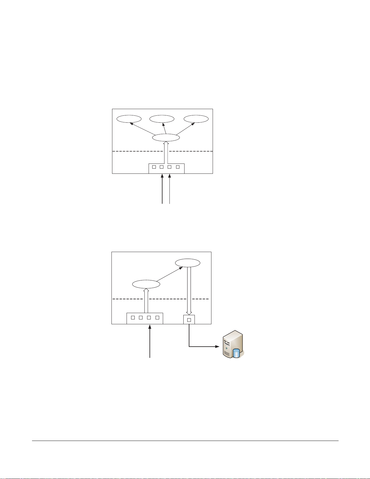
MAC Rewriting
The MAC rewrite feature allows the least significant byte (LSB) of a packet’s destination MAC address to
be overwritten with a user-specifed value. This feature may be used to load balance or redirect traffic.
P-Series Installation and Operation Guide, version 2.3.1.2 51
Page 52

This feature can be enabled per channel. When MAC rewrite is enabled, the P10 appliance classifies the
root@# pnic macrewrite-on 0
No channel number specified. Assuming channel 0
*** Enabling MAC rewrite on card:0 channel:0 is successful!
[root@localhost ~]# pnic showconf
No device number specified. Assuming device 0
####################### On MASTER FPGA #######################
Temporary Packet Linked-list Limit: unlimited.
Timeout for Flow Garbage Collection: 16 (seconds)
Truncation after Match Packet: full packet.
####################### On PCI FPGA #######################
DMA Burst Size: 1024 (Bytes).
DMA Flush Timer: 1 (ms).
Interrupt Frequency Timer: 1(ms).
DMA Capture: on.
MAC Rewrite state: CH0 - enabled; CH1 - disabled
Version : P_MAIN2.0.0.80
[root@localhost ~]#pnic updatemacvalue
No device number specified. Assuming device 0
Please input the hash index [0-255]: 47
The value to replace: 69
The MAC updating is done on register 0x4bc - index:47!.
[root@localhost ~]#
MAC Rewrite Enabled
LSB Rewritten for Entered Index
MAC Rewrite Enabled
incoming traffic into one of 256 hash buckets to determine the value to be written to the LSB of destination
MAC address. A hash function based on the source and destination IP addresses is used to calculate an
8-bit index for each incoming packet. The index is used to look up the LSB values to be written into the
packet.
To enable MAC rewriting:
Step Task
1
Enter the command pnic macrewrite-on 0 channel to enable MAC rewriting.
2 Verify that MAC rewrite is enabled using the command pnic showconf.
Two additional commands are available with this feature:
• pnic updatemacvalue—Assigns a new LSB for a particular index.
•
pnic getmachasindex—Obtains the hash index value for a particular source and destination IP
combination.
Figure 34:
In
1. MAC rewriting is enabled
2. The user associates an LSB value with a particular index value.
3. All packets with source and destination IP addresses
that hash to this index value then have the the
least significant byte of their destination MAC address overwritten with the user-entered LSB value.
Figure 34
52 Command Line Interface
Rewriting Destination MAC Addresses to Load Balance
Page 53

Removing VLAN Tags
The P-Series can strip the VLAN tag from incoming packets before they exit the egress port. Enable the
feature using the command
is enabled. If an incoming packet is untagged, it is not changed.
pnic vlan-remove-enable. The frame CRC is recalculated when this feature
View the enable state of this feature using the command
pnic showconf.
P-Series Installation and Operation Guide, version 2.3.1.2 53
Page 54

54 Command Line Interface
Page 55

Chapter 8 Compiling Rules
The P-Series Network Interface Card Compiler (pnic-Compiler) produces user-defined firmware for the
appliances. The user-defined input is a set of signature-based rules in Snort syntax, and compilation
directives. The output of the compiler is a Xilinx bit file and ASCII mapping files that map specified
signatures to internal configuration registers. The configuration registers are used to disable/enable rules or
block packets.
Creating Rules Files
Store rules files in a pnic-compiler sub-directory — for example pnic-compiler/rules. Force10
recommends not storing rules files elsewhere because this increases the length of the firmware file name.
Rules Capacity
The maximum rules capacity for the P10 is approximatly 14000 static rules or 200 dynamic rules. The
space required for a static rule depends upon its complexity.
Compiling Rules
Note: The pnic-Compiler is managed with GNU make.
To complile rules:
Step Task
1 Change directory to pnic-compiler.
2 Enter the command gmake. This command invokes the configuration script, the pnic-Compiler, and the
Xilinx compiler, in succession. Entering time gmake invokes the same processes, but this command
measures the compilation time as well.
3 The script prompts you for a number of compilation options. Refer to Table 8 for a description of ea ch
option, and enter a response for each.
P-Series Installation and Operation Guide, version 2.3.1.2 55
Page 56

Table 8 Compiler Configuration Options
Compilation Option Description
1 Target Device Choose the model of your appliance.
• The P10 requires type PB-10G-2P (see Figure 35 on page 58)
2 Match non-IP Traffic Answering Yes to this option matches packets that are not IPv4. This
option should be set to No if only IP traffic is allowed. (see Figure 35 on
page 58)
3 Match Fragmented IPv4
Packets or IPv4 Packets w/
Options
4 Rules File Specify the rules file that contains the Snort rules that will be compiled into
5 Dynamic Rules Enter the number of dynamic rules to synthesize .
Answering Yes to this option:
• Adds a rule to match fragmented IPv4 packets
• Adds a rule to match IPv4 packets with any option in the header (see
Figure 35 on page 58).
firmware.
• Include the relative path of the file in your entry.
• Your entry is used to create the firmware names.
• Enter null to create firmware with no static rules; compiling firmware
with no static rules maximizes dynamic rule capacity (see Figure 35 on
page 58).
Note: The script performs a syntax check on the input file. If there are
errors, you are prompted to enter the file name ag a i n. The ent ry m ust be
made at the prompt; if the Enter key is pressed erroneously such that the
entry cannot made at the prompt, enter Ctrl-C to halt the configuration
process, and then enter gmake to begin again.
• If you enter one of the sample Snort rules files, choose the minimum
number of dynamic rules; otherwise, the placing may fail.
• If you are using fewer static rules, you can increase the number of
dynamic rules up to approximately 30 for each channel (60 in total) (see
Figure 35 on page 58).
Note: The number of dynamic rules specified in this option is guideline that
the compiler uses to reserve space on the FPGA. The number you choo se
is the approximate
The amount of space a rule consumes varies based on the complexity of
the rule. Therefore, you might not be able to compile as many dynamic
rules as specified in this option if the rules are complex.
number of rules you will be able to configure at runtime.
6 meta.rules The pnic-Compiler prepends a set of fixed rules called meta.rules —
located in the pnic-compiler/rules directory. The rules in this file report on
flow information and provide compatibility with Snort; include or exclude
this file considering that including them allows you to run Snort on the DPI
interface.
It is best to include this file if Snort is being used as the front end. If not
using Snort as the front end, these rules should not be included or they
should be changed to accommodate other packet analysis requirements
(see Figure 36 on page 59).
56 Compiling Rules
Page 57

Table 8 Compiler Configuration Options
Compilation Option Description
7 Segmentation Evasion Rules The pnic-Compiler prepends a set of fixed rules—ca lled evasion.rules —
located in the pnic-compiler/rules directory. The rules help detect attacks
which are using strategic TCP segmentation to avoid detection.
It is best to include this file if Snort is being used as the front end. If not
using Snort as the front end, these rules should not be included or they
should be changed to accommodate other packet analysis requirements
(see Figure 36 on page 59).
8 Maximum String Specify the maximum number of bytes a single static rule can use for
content matching.
A low value truncates the match string and increases the number of rules
that can fit into the FPGA, but this is at the expense of increased false
positives.
A value lower than 1024 is not recommended unless you can cope with the
increased number of false positives through Snort or some other means
(see Figure 37 on page 60).
9 Firmware Name Enter a mnemonic name for the firmware you are about to create.
10 Confirmation Enter Yes to save the configuration and compile the Snort rules into
firmware (see Figure 37 on page 60).
P-Series Installation and Operation Guide, version 2.3.1.2 57
Page 58

Figure 35 pnic-Compiler Option 1-6
root@# gmake
Makefile:2: mtp_configuration: No such file or directory
bin/getparams2.sh
Please choose the target device
1) PB-10G-2P
#? 1
Do you want to support matching of non IPv4 and non IPv6 packets (like ARP/IPX etc)?
1) Yes
2) No
#? 2
Ethernet types allowed
Do you want to match packets that are IP fragments or have any IPV4 options?
1) Yes
2) No
#? 2
no fragments or IPv4 options
Enter filename containing rules to compile (enter "null" for no rules): snort/dos.rules
1+1+1+1
******************************************************
Verified 0 conforming signatures in file snort/rules.sample.
******************************************************
Channel 0 Dynamic rules
Please choose how many dynamic rules (5-20 recommended)
Dynamic rules are rules that can be added without recompiling
the firmware. They can be added at runtime through the UI
Dynamic rules only work for Ipv4 traffic for now
1) 0 5) 20 9) 60 13) 100 17) 180 21) 260 25) 340
2) 2 6) 30 10) 70 14) 120 18) 200 22) 280 26) 360
3) 5 7) 40 11) 80 15) 140 19) 220 23) 300 27) 380
4) 10 8) 50 12) 90 16) 160 20) 240 24) 320 28) 400
#? 5
Enter command gmake from
pnic-compiler directory
58 Compiling Rules
Page 59

Figure 36
Channel 1 Dynamic rules
Please choose how many dynamic rules (5-20 recommended)
Dynamic rules are rules that can be added without recompiling
the firmware. They can be added at runtime through the UI
Dynamic rules only work for Ipv4 traffic for now
1) 0 5) 20 9) 60 13) 100 17) 180 21) 260 25) 340
2) 2 6) 30 10) 70 14) 120 18) 200 22) 280 26) 360
3) 5 7) 40 11) 80 15) 140 19) 220 23) 300 27) 380
4) 10 8) 50 12) 90 16) 160 20) 240 24) 320 28) 400
#? 5
Do you want to include the default meta rules?
alert tcp any any -> any any (msg:"Z SYN"; flags:S,12; S:1; R:2; C:3;)
alert tcp any any -> any any (msg:"Z SYNACK"; flags:SA; S:1; R:2; C:5;)
alert tcp any any -> any any (msg:"Z TCP within was issued previously for this flow = capture flow"; S:32; R:2; C:32;)
alert udp any any -> any any (msg:"Z UDP within was issued previously for this stream = capture stream"; S:64; R:2; C:64;)
alert tcp any any -> any any (msg:"Z SAPU TCP Flags"; flags:SAPU;)
alert tcp any any -> any any (msg:"Z FU TCP Flags"; flags:FU;)
alert tcp any any -> any any (msg:"Z PF TCP Flags"; flags:PF;)
alert tcp any any -> any any (msg:"Z UP TCP Flags"; flags:UP;)
alert tcp any any -> any any (msg:"Z Zero TCP Flags"; flags:0;)
1) Yes
2) No
#? 1
Do you want to include the segmentation evasion rules?
alert tcp any any -> any any (msg:"Z Evasion: State 2 Fragment of size 1 "; dsize: 1; S:4; R:1; C:16;)
alert tcp any any -> any any (msg:"Z Evasion: State 1 First fragment of size 0 <> 10 = state 1"; dsize: 0 <> 20; S:4; R:1; C:8;)
alert tcp any any -> any any (msg:"Z Evasion: State 2 Second fragment of size 0 <> 10 = capture flow"; dsize: 0 <> 20; S:8; R:1;
C:16;)
alert tcp any any -> any any (msg:"Z Evasion: State 3 Capture flow fragments of size 0 <> 10"; dsize: 0 <> 100; S:16; R:2; C:17;)
1) Yes
2) No
#? 1
Selecting Yes is recommended
when using Snort
Selecting Yes is recommended
when using Snort
pnic-Compiler Option 6-7
P-Series Installation and Operation Guide, version 2.3.1.2 59
Page 60

Figure 37 pnic-Compiler Option 8-9
Please choose the maximum number of bytes per signature (1024 recommended).
Selecting a small number allows larger sets of signatures
at the expense of more false positives.
1) 16
2) 32
3) 64
4) 96
5) 128
6) 256
7) 512
8) 1024
#? 8
Enter the firmware base-image name (press the Enter key to retain the default name:
"snort_dos.rules.xc4vlx200-ff1513.10.10.32"): snort_dos.rules
Selected configuration:
Signature files : snort/dos.rules
Firmware name : snort/dos.rules
Firmware file : snort_dos.rules.bit
Mapping for ch 0 : snort_dos.rules.0.mapping
Mapping for ch 1 : snort_dos.rules.1.mapping
PNIC device : xc4vlx200-ff1513
Include meta rules : yes
Include evasion rules : yes
Dynamic rules CH 0 : 10
Dynamic rules CH 1 : 10
Max string : 32
To generate new PNIC firmware with the above configuration
Select Save_configuration and run make
The compilation process will create the file: snort_rules.sample.xc4vlx200-ff1513.20.20.2048.N.Y.N.N
1) Save_configuration
2) Exit
Summary of configuration
Starting and Stopping the pnic-Compiler
Enter the keyboard command Ctrl-C or a SIGINT signal to interrupt the compilation or configuration
process. Enter
restarts at the point where it was halted; the configuration process restarts from the beginning.
During compilation, enter
options. This erases the current configuration and resets the compilation process. Previously generated
firmware files are not
gmake to restart the process from where it was interrupted. The compilation process
Ctrl-C followed by gmake clean to regenerate firmware with different
erased.
60 Compiling Rules
Page 61

Configuration and Generated Files
Table 9 describes the files that are used or generated by the pnic-Compiler.
Table 9 Configuration and Generated Files
File Description Location
pnic_*.bit Generated after compiling static rules. They
are then renamed and copied to /usr/local/
pnic/firmware. When selecting firmware, the
.bit files are symbolically linked to the
corresponding renamed files in the firmware
directory.
pnic_*.mapping Generated after compiling static rules. They
are then renamed and copied to /usr/local/
pnic/firmware. When selecting firmware, the
.mapping files are symbolically linked to the
corresponding renamed files in the firmware
directory.
<firmware_filename>.bit Firmware files for Channel 0 and Channel 1.
They are the renamed .bit files that were
generated after compiling static rules. When
selecting firmware, these are the files to
which the .bit files in /usr/local/pnic/0 are
symbolically linked.
<firmware_filename>.mapping Firmware files for Channel 0 and Channel 1.
They are the renamed .mapping files that
were generated after compiling static rules.
When selecting firmware, these are the files
to which the .mapping files in /usr/local/pnic/
0 are symbolically linked.
/usr/local/pnic/0
/usr/local/pnic/0
/usr/local/pnic/firmware/
<firmware_filename>
/usr/local/pic/firmware/
<firmware_filename>
pnic_*.bin Contain compiled dynamic rules for Channel
0 and Channel 1.
pnic_*.custmapping Contain the capture/forward policies for each
rule on Channel 0 and Channel 1.
rules.custom Contains dynamic rules written in Snort
syntax.
P-Series Installation and Operation Guide, version 2.3.1.2 61
/usr/local/pnic/0
/usr/local/pnic/0
/usr/local/pnic/0
Page 62

Firmware Filenames
The pnic-Compiler creates new firmware — in the /usr/local/pnic/firmware directory — consisting of four
.bit files and eight .mapping files.
The default firmware filenames follow a naming convention designed to identify three properties:
• The appliance that can use it
• The number of dynamic rules
• The maximum allowed number of half-bytes per rule
Firmware files have the format:
<name>.<type>.<dynamic{0|1}>.<maxstring>.{0|1}.{bit|mapping}
Table 10 describes each of the elements in this format.
Table 10 Firmware Filename Description
Element Description
<name> This field is a mnemonic name identifying the original rules file you supplied during the
compilation of the firmware.
<type> This field identifies the card type. The P10 is represented by xc4vlx200-ff1513.
<dynamic{0|1}> This field is the estimated number of dynamic rules that you can enter at runtime for the two
channels.
<maxstring> This field is the maximum number of half-bytes the compiler allocates for each rule. A
typical value is 2048 to indicate that the compiler truncates match string to 1024 bytes.
Typically a value is 2048, which does not result in any truncation. Lower values are possible
and result in a larger number of rules, but this increases the probability of false positives for
rules with truncated match strings.
{0|1} This field indicates whether the file is for Channel 0 or Channel 1.
{bit|mapping} The compiling process generates 12 files which together make firmware. 8 files have the
extension .mapping, and 4 have the extension .bit.
Compiler Errors
• If too many dynamic rules are specified in Option 9 of the compiler configuration phase, the
compilation process fails, and you receive a “Error-PhysDesignRules” error message. In this case,
enter
gmake clean to erase the current configuration and begin again.
• If too many rules stored in the rules file specified in Option 6 of the compiler configuration phase, the
compilation process fails. In this case, enter
again.
gmake clean to erase the current configuration and begin
62 Compiling Rules
Page 63

Chapter 9 Writing Rules
P-Series rule syntax is based on Snort. Both rule structures are described in this chapter.
• Snort Rule Syntax on page 63
• P-Series Rule Syntax on page 66
Snort Rule Syntax
Snort rules are descriptions of traffic plus a prescribed action that is taken if a packet matches that
description. Rules are divided into two sections:
• Header: The header contains the action, protocol, source and destination IP addresses (with subnet
masks), and the source and destination ports.
• Options: The options section contains alert messages, and specifies values to search for inside the
packet.
Table 11 shows the syntax for Snort rules, and Table 12 shows an example. The text preceding parenthesis
is the header, and the section enclosed in parenthesis contains the rule options. The words before the colons
in the rule options section are option keywords. Rules that span multiple lines must have a backslash at the
end of the line. All rules and options must be punctuated with a semicolon.
Table 11 Snort Rule Syntax
action protocol source_address source_port -> destination_address destination_port\
(content:”data_string”; msg:”message”);
Table 12 Snort Rule Example
alert tcp any any -> 192.168.1.0/24 111 (content:”| 00 01 86 a5 |”; msg:”mounted access”);
Snort Rule Headers
Action
The first item in a rule is the action keyword. It dictates how Snort is to handle a packet that matches the
rule. All of the elements in a rule must be true for Snort to execute the action. There are five actions
keywords in Snort:
• alert directs Snort to generate an alert and log the packet.
• log directs Snort to log the packet.
P-Series Installation and Operation Guide, version 2.3.1.2 63
Page 64

• pass directs Snort to ignore the packet.
• activate directs Snort to generate an alert and activate another specified rule.
• dynamic directs Snort to disregard the rule until it is activated by another rule. Once activated, the
action defaults to log.
Note: The default actions for the P-Se ries are diff erent from Snort. See “P-Series Rule Syntax” on page 66.
The meaning of the Snort action keyword dynamic
rules in Snort are rules that must be activated, where as with the P-Series, dynamic rules are any rules that
are uploaded to the FPGA without creating new firmware.
is not the same as P-Series dynamic rules. Dynamic
Protocol
Snort supports four protocols: tcp, udp, icmp, or ip. The protocol keyword follows the action keyword.
Source Addresses
The source address and port follow the protocol keyword. Addresses are written using dotted-decimal
notation with the subnet mask in CIDR block notation. For example, the address/CIDR combination
192.168.1.0/24 signifies a block of addresses from 192.168.1.1 to 192.168 .1.255. The keyword any may be
used to define any source address.
The address field can be negated by placing an exclamation point before the address. This operator
specifes all addresses other than the one contained in the rule. The rule in Ta ble 13 indicates specifes all
traffic originating from outside the local network and destined for the local network.
Note: The negation operator may not be placed before the keyword any.
Table 13 Rules Containing Address Negation
alert tcp !192.168.1.0/24 any -> 192. 18 6 .1 .0/ 24 111(content:”| 00 01 86 a5 |”; msg:”mounted access”;)
Lists of IP addresses can be specified by placing the addresses in brackets and separating each address with
a comma; do not include spaces. Table 14 shows an example of a rule containing multiple addresses.
Table 14 Rules Containing Multiple IP Addresses
alert tcp ![192.168.1.0/24,10.1.1.0/24] any -> [ 192.186.1.0/24,10.1.1.0/24] 111(content:”| 00 01 86 a5 |”;\
msg:”mounted access”;)
64 Writing Rules
Page 65

Ports
Port numbers may be specified by the keyword any, a single port number, ranges, and by negation. any
specifies any port. Static ports are indicated by a single port number, for example, 23 for Telnet. Port
ranges can be specified using a colon as a range operator. It can be applied in three ways, as shown by
Table 15.
Table 15 Rules Containing the Port Number Range Operator
log udp any any -> 192.168.1.0/24 1:1024 log udp
log tcp any any -> 192.168.1.0/24 :600 0
log tcp any :1024 -> 192.168.1.0/24 500:
• A colon between two port numbers indicates all ports between those ports, including the specified
ports.
• A colon before a port number indicates all ports less than or equal to the specified port.
• A colon after a port number indicates all ports greater than or equal to the specifed port.
The negation operator can also be used in combination with port numbers. The rule in Table 16 logs all
TCP traffic destined for ports other than port 6000 on the local network.
Table 16 Rules Containing the Port Number Negation Operator
log tcp any any -> 192.168.1.0/24 !6000:6000
Note: The negation operator may not be placed before the keyword any. The ICMP protocol does not
require a port number.
Direction Operator
The direction operator, ->, indicates direction of the traf fic to whic h the rule applies. The source IP address
and port are on the left side of the direction operator, and the destination address and port are on the right
side of the operator.
There is also a bidirectional operator,
the specified addresses and ports. This operator can be used for analyzing both sides of a conversation. An
example of the bidirectional operator being used to record both sides of a Telnet session is shown in
Table 17.
Table 17 Rules Containing the Bidirectional Operator
log tcp !192.168.1.0/24 any <> 192.168.1.0/24 23
<>. This directs Snort to consider traffic originating from either of
P-Series Installation and Operation Guide, version 2.3.1.2 65
Page 66

Destination Address and Port
The destination address and port follow the direction operator. The syntax of these parameters are the same
as the source address and port. See “Source Addresses” on page 64, and “Ports” on page 65.
Snort Rule Options
Options are made of a keyword and an argument. An argument is the packet data against which the rule is
matched. Option keywords are followed by a colon, and each option is puncutated with a semi-colon.
Table 19 lists the option keyword s that the P-Series supports.
P-Series Rule Syntax
P-Series rules have a syntax that is slightly different from Snort rules. P-Series rules have the following
syntax:
capture/forward_policy on channel Snort_rule
• capture/forward policy can have four values: alert, permit, divert, or deny. These settings are
described in
• channel can be c0 for Channel 0, c1 for Channel 1, or all for both channels.
• Snort_rule is a rule written in Snort syntax.
Table 5 on page 28.
Table 18 shows an example P-Series rule.
Table 18 P-Series Rule Example
alert on c1 any any -> any any (msg:"Z Default rule fragmented ip";)
Note: P-Series does not support the Snort action keywords log, pass, activate, and dynamic. P-Series
supports the action keywords alert, permit, divert, and deny.
P-Series Supported Snort Keywords
Table 19 lists Snort keywords that the P-Series supports for both dynamic and static rules.
Table 19 Supported Snort Keywords for Static and Dynamic Rules
Keyword Static Dynamic
ack Yes Yes
content Yes, no negative. No
66 Writing Rules
Page 67

Table 19 Supported Snort Keywords for Static and Dynamic Rules
Keyword Static Dynamic
depth No No
dsize Yes No
flags Yes Yes, no wild card
flow Yes No
fragbits Yes No
fragoffset Yes No
icmp_id Yes Yes
icmp_seq Yes Yes
icode Yes Yes
id Yes Yes
ip_proto Yes Yes
itype Yes Yes
offset No No
nocase Yes No
protocol ICMP, UDP, TCP, IP ARP, ICMP, UDP, TCP, IP
seq Yes Yes
source address Yes Only /8/16/24/32 masks
destination address Yes Only /8/16/24/32 masks
source port Yes Yes, no ranges
destination port Yes Yes, no ranges
tos Yes Yes
ttl Yes Yes
uricontent Yes, no negative. No
window Yes No
within No No
P-Series Installation and Operation Guide, version 2.3.1.2 67
Page 68

Writing Stateful Rules
New Packet
Calculate Cf
Address
Bitwise OR
Cf | new state
Update Cf
Cf
Timed out
New Flow
yes
yes
fn9000017
C[0]=1
Stateful matching improves the accuracy of detection because it adds ordering when specifying behaviors
across multiple matching events. State transitions in the P-Series follow a non-cyclic pattern; no state
transitions may erase any of the previous states. New state transitions are simply recorded via a
non-destructive, additive operation.
As new states are produced, they are bitwise “OR-ed” with the current states contained in the per-flow
register C
where old state is removed after a set amount of time. It allows a deterministic wire-speed state
management algorithm while guaranteeing that no match events are ever lost due to resource constraints.
Figure 38 shows the state matching algorithm. Note that the only time some state is erased is in the case of
a timeout.
Figure 38 State Management Algorithm
., which is 16 bits wide. This method is different from stateful matching in software systems,
f
Stateful Matching
Each signature i contains a pattern matching expression mi that is compared to the incoming data stream in
real time (time t). In addition, each signature may contain - at your discretion - three values, s, c, and r,
which respectively specify:
• The pre-match state condition necessary for
• The post-match state condition applied after the signature has
• A directive indicating what to
The s an
sub-stream, and the r value is used to direct the packet storage.
68 Writing Rules
d c values are used to manage a per-flow register Cf, where the subscript f is the flow, or
do with the matched packet
the signature to match (in addition to mi)
matched
Page 69

Pre-match Condition — the S Value
If m
i
s
i
t
C
f
t 1–
&()s
i
t
=∧
⎩⎭
⎨⎬
⎧⎫
then cp
i
t
, cielse cp
i
t
0=
⎩⎭
⎨⎬
⎧⎫
,= Equation 3
C
f
t
cp
i
t
C
f
t 1–
Equation 4
∑
=
The value in register Cf is presented to all the signatures simultaneously during matching.
C
must have all the bits specified by si (in addition to matching mi) in order for the signature i to trigger. In
f
other words, if the result of the logical “AND” of register C
signature is allowed to trigger. Otherwise the signature is not triggered. Therefore value s
the pre-match bit pattern.
with si is non-zero and equal to si, the
f
is referred to as
i
Post-match Condition — the C Value
The ci value is the post-match bit pattern defined by the signature i. If mi matches in the data stream, and
the pre-match condition is met, c
is written back to C
In general for each signature i at time t:
.
f
is logically “OR-ed” with the existing value in register Cf, and the result
i
where /\ is a logical “AND” operator, & is a bitwise AND, Sigma is a bit-wise “OR” of several terms, and |
is a bitwise OR of two terms.
Equation 3 states that if there is a match m
is enabled.
cp
i
Equation 4 states that at each cycle, the register C
the signatures, and a final bitwise OR with the previous state.
When a stateful flow is older than a timeout value, C
the first state of a flow should have s=1.
and the pre-match condition holds, the post-match condition
i,
is updated by the bitwise OR of all the cpi values of all
f
(t-1)
is ignored. It is replaced by 0x1. So, the rule for
f
Packet Handling — the R Value
The constant ri is a flag that tells the hardware what to do with a packet that has been matched to signature
i. The memory used to store the matched packets is divided into T e mporary Memory and Match Memory. If
a packet is stored in Match Memory, action is requested from the host to process the matched packet. If a
packet is stored in Temporary Memory, no action is requested from the host, as this represents only a
partial match.
P-Series Installation and Operation Guide, version 2.3.1.2 69
Page 70

When a packet is stored in either T emporary Memory or Match Memory, a pointer to the previously stored
packet in the same flow (contained in a portion of the flow register C
) is also stored. Thus a packet stored
f
in Match Memory may reference another packet stored in Temporary Memory, which in turn may
reference more packets, thus forming a linked list of partial matches, starting with a packet stored in Match
Memory.
The values for r
have the following meanings:
i
1: store the packet in Temporary Memory
2: store the packet in Match Memory and notify host software
Note: If the Hash key option is selected, the R=2 flag no lo n ger ca uses the packet to be stored in
Temporary Memory.
Stateful Rule Examples
Table 20 Stateful Matching Signatures
Signature 1: alert on c0 tcp any any -> any any (msg:
Signature 2: alert on c0 tcp any any -> any any (msg:
Signature 3: alert on c0 tcp any any -> any any (msg:
Signature 4: alert on c0 tcp any any -> any any (msg:
Signature 5: alert on c0 tcp any any -> any any (msg:
"SYN"; flags:S; S:1; R:0; C:3;)
"ack"; flags:A+; S:2; R:1; C:4;)
"ack"; flags:A+; S:4; R:2; C:4;)
"frag"; dsize: 0 <> 100; S:1; R:1; C:9;)
"frag"; dsize: 0 <> 100; S:8; R:1; C:16;)
Signature 6: alert on c0 tcp any any -> any any (msg:
"frag"; dsize: 0 <> 100; S:16; R:2; C:16;)
In Table 20:
• Signature 1 matches any TCP SYN packet, erasing any expired C
meaning a SYN is present — it sets bits 0 and 1 (value 3) in the C
register; if this signatures triggers -
f
register. The SYN packets is
f
discarded (R=0).
• Signature 2 triggers if Signature 1 has triggered (the C
contains an ACK bit. The result for this match is that bit 2 (value 4) is set in the C
register having bit 1 set) and a TCP packet
f
register. The packet
f
is stored in Temporary Memory (R=1).
• Signature 3 triggers if
Signature 2 has triggered (the Cf register having bit 2 (value 4) set) and another
later TCP packet contains an ACK bit. The result for this match does not modify the existing content
of the C
register. The packet is stored in Match Memory, referencing the packet of Signature 2. The
f
DPI driver then presents to the host the packet matched by 2, followed by the packet matche d by 3,
through the DPI network interface.
70 Writing Rules
Page 71

You can inspect Signatures 4, 5, and 6, and verify that they trigger a match and place a packet in Match
Memory — thus alerting the host — if three consecutive packets are seen with size between 0 and 100. The
third packet references the previous two stored in Temporary Memory. Thus, once the third packet is
received, the three segments are presented to the host through the DPI network interface. Notice that the bit
pattern used in the two rules avoids collision with the previous rule if the flow hashing also happens to
collide.
The meta.rules File
The meta.rules file — located in the pnic-compiler/rules directory — specifies a number of stateful rules to
be used with standard Snort rules (which use the Flow keyword). In addition, these rules implement a
stateful mechanism to circumvent some common forms of TCP IDS evasion. The meta rules are given in
Appendix C, on page 123.
Support for Snort's flow Keyword
The two stateful rules in Table 21 initiate a new flow if a SYN or a SYN-ACK are seen. A Snort flowestablished keyword is translated to S:4 and S:2 for client-to-server and server-to-client flows,
respectively. These keywords are automatically inserted by the PNIC-Compiler when a flow-established
keyword is encountered during compilation. You can also insert the keywords directly into your rules.
Table 21 Flow Established Rules
alert tcp any any -> any any (msg:"Z SYN"; flags:S,12; S:1; R:2; C:3;)
alert tcp any any -> any any (msg:"Z SYNACK"; flags:SA; S:1; R:2; C:5;)
Handling Segmentation Evasion
T ools like fragroute or Nessus are used to fragment the packet payload in several TCP segments in order to
evade packet-based signature systems. The stateful rules in Table 22 detect the arrival of packets exhibiting
an anomalous use of TCP segmentation.
P-Series Installation and Operation Guide, version 2.3.1.2 71
Page 72

The start of the state machine is prompted by a SYN; state 1 is reached if a packet of length greater than 0
but less than 20 is detected; state 2 is reached if a packet of length 1 is received right after a SYN or a
second packet of length greater than 0 but less than 20 is detected; the final state is reached if a packet of a
length between 0 and 100 is seen. This state diagram was derived from observing common fragmentation
evasion patterns; it seems to catch most of them. More complex state diagrams can also be devised at your
discretion.
Table 22 TCP Packets with Anomalous Segmentation
alert on c0 tcp any any -> any any (msg:"Z Evasion: State 2 Fragment of size 1 "; dsize: 1; S:4; R:1; C:16;)
alert on c0 tcp any any -> any any (msg:"Z Evasion: State 1 First fragment of size 0 <> 20 = state 1"; dsize: 0 <>
20; S:4; R:1; C:8;)
alert on c0 tcp any any -> any any (msg:"Z Evasion: State 2 Second fragment of size 0 <> 20 = capture flow";
dsize: 0 <> 20; S:8; R:1; C:16;)
alert on c0 tcp any any -> any any (msg:"Z Evasion: State 3 Capture flow fragment s of size 0 <> 100"; dsize: 0 <>
100; S:16; R:2; C:16;)
Support for Snort's within Keyword
Many buffer-overflow detection rules use a within keyword that verifies that an end-of-line character is
received within a certain number of bytes from the start of the session.
If the within statement is for a large number of bytes, the check needs to be performed across TCP
segments. In this case, several packets must be captured to find the end-of-line character (or whatever the
character might be). For this reason, within statements capture the entire flow.
The within statements are translated by the PNIC-Compiler upon setting the S:32 and S:64 bits. This
causes two rules to trigger the capturing of TCP and UDP flows.
Table 23 shows two rules which trigger the capturing of TCP and UDP flows.
Table 23 Capturing TCP and UDP Flows
alert on c0 tcp any any -> any any (msg:"Z TCP within was issued previously for this flow = capture flow"; S:32;
R:2; C:32;)
alert on c0 udp any any -> any any (msg:"Z UDP within was issued previously for this stream = capture stream";
S:64; R:2; C:64;)
72 Writing Rules
Page 73

Anomalous TCP Flags
Some TCP packets with anomalous flags are captured by default to provide scan detection software
diagnosis information. Table 24 shows rules which were derived from the Snort scan pre-processor.
Table 24 TCP Packets with Anomalous Flags
alert on c0 tcp any any -> any any (msg:"Z SAPU TCP Flags"; flags:SAPU;)
alert on c0 tcp any any -> any any (msg:"Z FU TCP Flags"; flags:FU;)
alert on c0 tcp any any -> any any (msg:"Z PF TCP Flags"; flags:PF;)
alert on c0 tcp any any -> any any (msg:"Z UP TCP Flags"; flags:UP;)
alert on c0 tcp any any -> any any (msg:"Z Zero TCP Flags"; flags:0;)
The compiler also automatically produces rules that match all packets that are IP fragments or have IP
options. These rules are not specified in the pnic.meta file as they can be more efficiently implemented by
the compiler directly.
P-Series Installation and Operation Guide, version 2.3.1.2 73
Page 74

74 Writing Rules
Page 75

Chapter 10 Firewall
Deploying the P-Series as a Firewall
By default the P-Series is an IDS/IPS system; the P-Series forwards all traffic by default and blocks
packets only if it matches a rule. You can deploy the P-Series as a limited firewall by enabling Drop mode.
In Drop mode, the P-Series blocks all traffic by default and forwards traffic only if it matches a rule.
P-Series Installation and Operation Guide, version 2.3.1.2 75
Page 76

Enabling the Firewall
[root@localhost ~]# pnic default-drop-disable
No device number specified. Assuming device 0
*** Disabling Default-Packet-Drop on card:0 successful!
*** Te mporary memory enabled.
[root@localhost ~]# pnic default-drop-enable
No device number specified. Assuming device 0
*** Enabling Default-Packet-Drop on card:0 successful.
*** Te mporary memory disabled.
[root@localhost SW]# pnic showconf
No device number specified. Assuming device 0
DMA Capture : on
MAC Rewrite state : CH0 - disabled; CH1 - disabled
Default Drop Packet : enabled
Temporary memory : disabled
Aggregate mode : enabled
PHY passive mode : disabled
####################### On MASTER FPGA #######################
Per Flow Packet Limit : unlimited
Timeout for Flow Garbage Collection : 16
Truncation after Match Packet : full packet
####################### On PCI FPGA #######################
DMA Burst Size : 1024 (Bytes)
DMA Flush Timer : 1 (ms)
Interrupt Frequency Timer : 5 (ms)
Version : P2.3.0.2
[root@localhost SW]#
Drop mode Enabled
Drop mode Disabled
Verify Drop mode is Enabled
Enable Drop mode using the command pnic default-drop-enable. Disable Drop mode usin g the command
pnic default-drop-disable. These commands are shown in Figure 39.
Figure 39
Enabling and Disabling Drop Mode
76 Firewall
Page 77

Allowing Traffic through the Firewall
To allow packets through the firewall you must write rules so that packets that you want the appliance to
forward match those rules. Rules can be as simple as allowing traffic destined to a port. Stateful rules can
be used to allow all traffic for an established connection. To allow non-IP traffic to pass through the
firewall, you must select “Yes” for compiler option 2, as described in Table 8 on page 56.
Sample rules for a firewall deployment are available in file pnic-compiler/rules/fw.rules.
Writing Rules for a Firewall Deployment
Rules for a firewall deployment are written in the same Snort-based syntax as IDS/IPS rules. The
difference is that you must describe packets that you want to forward, rather than block. See P-Series Rule
Syntax on page 66.
In Table 25 stateful rules are used to allow specified traffic into the internal network. Notice that in the
incoming direction, the policies require that the packet be destined to a set of allowed ports, while in the
outgoing direction, there is no port requirement. This asymmetry produces typical firewall behavior.
The Drop mode can also accommodate arbitrary rules that do not assume an inside and outside interface.
This is an attractive quality since the notion of inside and outside is often blurred in modern network
topologies. Also note that traditional IPS and IDS rules can be coupled with the firewall rules to block
packets and/or capture suspicious packets.
P-Series Installation and Operation Guide, version 2.3.1.2 77
Page 78

Table 25 Sample Firewall Rules
#permit: let through and do not log to the host
#alert: let through and log to the host
#deny: DO NOT let through and do not log to the host
#divert: DO NOT let through and log to the host
# S:<precondition>; C:<postcondition> R:<logging>
# A packet is matched if precondition matches the current state of that flow;
# in that case the postcondition is ORed and app lied to rewrite the state of that flow;
# A precondition of 1 starts a new flow
# logging should be set to 2 for most cases; see the user manual for R:1
# Topology assumption
#c0 : Unsecured EXTERNAL network
#c1 : Secured INTERNAL network
# specify here your inside networks
#var INTERNAL 192.168.50.0/24
var INTERNAL any
var EXTERNAL any
# specify here your outside DNS servers
#var DNS [10.11.0.1, 10.11.0.2]
var DNS any
var DNSPORT 53
#specify here the services provided from the inside network
#var ALLOWEDPORTS [21,22,25]
var ALLOWEDPORTS 22
#allow INTERNAL network to poke a hole through the firewall for TCP services
permit on c1 tcp $INTERNAL any -> $EXTERNAL any (msg:"Z SYN"; flags:S; S:1; R:2; C:3;)
permit on c0 tcp $EXTERNAL any -> $INTERNAL any (msg:"Z SYNACK"; flags:SA; S:2; R:2; C:4;)
#allow EXTERNAL network to poke a hole through the fire wall if accessing any of the ALLOWEDPORTS
permit on c0 tcp $EXTERNAL any -> $INTERNAL $ALLOWEDPORTS (msg:"Z SYN"; flags:S; S:1; R:2; C:3;)
permit on c1 tcp $INTERNAL $ALLOWEDPORTS -> $EXTERNAL any (msg:"Z SYNACK"; flags:SA; S:2; R:2; C:4;)
#allow TCP packets on the established flow/hole (INTERNAL <--> EXTERNAL)
permit on all tcp any any -> any any (msg:"Z TCP flow allowed"; S:4; R:2; C:4;)
#allow INTERNAL network to poke a hole through the firewall for DNS queries
permit on c1 udp $INTERNAL any -> $DNS $DNSPORT (msg:"DNS query"; S:1; R:2; C:9;)
permit on c0 udp $DNS $DNSPORT -> $INTERNAL any (msg:"DNS reply"; S:8; R:2; C:16;)
#allow UDP packets for the established UDP flow/holes (INTERNAL <--> DNS)
permit on all udp any any -> any any (msg:"Z UDP flow allowed"; S:16; R:2; C:16;)
#bad stuff; do not let though and do not log
deny on all tcp any any -> any any (msg:"Z SAPU TCP Flags"; flags:SAPU;)
deny on all tcp any any -> any any (msg:"Z FU TCP Flags"; flags:FU;)
deny on all tcp any any -> any any (msg:"Z PF TCP Flags"; flags:PF;)
deny on all tcp any any -> any any (msg:"Z UP TCP Flags"; flags:UP;)
deny on all tcp any any -> any any (msg:"Z Zero TCP Flags"; flags:0;)
78 Firewall
Page 79

Appendix A Command Line Reference
The command line interface (CLI) is an alternat ive to the GUI for managing the appliance. A
script called pnic is used to perform the same management functions as the GUI.
Invoke the pnic script using the commands in this chapter; the OS environment variables are
set such that these command can be executed from any path.
• pnic aggregate-mode-disable on page 80
• pnic aggregate-mode-enable on page 81
• pnic apply-firmware on page 81
• pnic capture-off on page 83
• pnic capture-on on page 83
• pnic cardstatus on page 84
• pnic compilerules on page 85
• pnic default-drop-disable on page 85
• pnic default-drop-enable on page 86
• pnic diag on page 86
• pnic flow-teardown-disable on page 88
• pnic flow-teardown-enable on page 88
• pnic gui on page 90
• pnic help on page 92
• pnic linkdown on page 93
• pnic linkup on page 93
• pnic loadconf on page 94
• pnic loadeproms on page 96
• pnic loadparams (deprecated) on page 96
• pnic loadrules on page 98
• pnic macrewrite-off on page 99
• pnic macrewrite-on on page 99
• pnic off (deprecated) on page 100
• pnic on (deprecated) on page 101
• pnic params on page 102
• pnic passive-mode-disable on page 102
• pnic passive-mode-enable on page 103
• pnic resetconf on page 104
• pnic restart on page 104
• pnic sguil-sensor-start on page 105
• pnic sguil-sensor-stop on page 107
P-Series Installation and Operation Guide, version 2.3.1.2 79
Page 80

• pnic showconf on page 108
[root@localhost SW]# pnic aggregate-mode-disable
No card number specified. Assuming card 0
*** Aggregate mode disabling on card:0 successful.
[root@localhost SW]#
• pnic show-firmwares on page 108
• pnic showtech on page 109
• pnic start on page 110
• pnic stop on page 111
• pnic temp-mem-disable on page 112
• pnic temp-mem-enable on page 112
• pnic updatemacvalue on page 113
• pnic vlan-remove-disable on page 114
• pnic vlan-remove-enable on page 114
• pnic web-gui-start on page 115
• pnic web-gui-stop on page 116
Note: The P10 does not support multiple network interface cards. Therefore, the only
valid entry for the number variable is 0.
Card 0 and Channel 0 are assumed for all commands if the card and
are not specified.
nu
mber options
pnic aggregate-mode-disable
Receive client-to-server and server-to-client traffic on different ports.
Syntax
Parameters
Command
History
Examp
pnic aggregate-mode-disable [number]
Enable aggregate mode using the command
number
Version 2.3.0.0 Introduced
le
Figure 40 pnic aggregate-mode-disable Command Example
pnic aggregate-mode-enable.
(OPTIONAL) Enter the number of the network interface card.
Range: 0-5
Default: 0
80 Appendix A
Page 81

Related
[root@localhost SW]# pnic aggregate-mode-enable
No card number specified. Assuming card 0
*** Aggregate mode enabling on card:0 successful.
[root@localhost SW]#
Commands
pnic aggregate-mode-enable Rece ive both client-to-server and server-to-client traf fic on
pnic aggregate-mode-enable
Receive both client-to-server and server-to-client traffic on one port. This is the default
behavior.
one port.
Syntax
Parameters
Command
History
Example
Related
Commands
pnic aggregate-mode-enable [number]
Disable aggregate mode using the command
number
Version 2.3.0.0 Introduced
(OPTIONAL) Enter the number of the network interface card.
Range: 0-5
Default: 0
pnic aggregate-mode-disable.
Figure 41 pnic aggregate-mode-enable Command Example
pnic aggregate-mode-disable Receive client-to-server and server-to-client traffic on
different ports. This is the default behavior.
pnic apply-firmware
Apply a specific firmware image to the card. You must specify either the firmware name or
the complete path of the firmware.
Syntax
P-Series Installation and Operation Guide, version 2.3.1.2 81
pnic apply-firmware [number]
Page 82

Parameters
[root@localhost SW]# pnic apply-firmware
No card number specified. Assuming card 0
Do you really want to apply a new firmware for card0 (y/n)? y
Please enter the path or name of the firmware to apply: /usr/local/
pnic/firmware/null.xc4vlx200-ff1513.50.50.2048
Compiling dynamic rules for pnic0
Parsing the dynamic rules for channel0
Parsing the dynamic rules for channel1
Interface pnic0 is down
Waiting for matching to stop ...
Loading rule firmwares ............ Done.
Loading pass/block settings ... Done.
Loading dynamic rules ... Done.
***************************************
Interface pnic0 is up
MTU set to 9264 bytes
***************************************
Version : P_MAIN2.2.0.058
The firmware image null.xc4vlx200-ff1513.50.50.2048 was successfully
applied to card0
[root@localhost SW]#
[root@localhost SW]# pnic apply-firmware
No card number specified. Assuming card 0
Do you really want to apply a new firmware for card0 (y/n)? n
[root@localhost SW]#
number
(OPTIONAL) Enter the number of the network interface card.
Range: 0-5
Default: 0
Command
History
Example
Version 2.3.0.0 Introduced
Figure 42
pnic apply-firmware Command Example 1
82 Appendix A
Related
Commands
Figure 43
pnic show-firmwares Display the available firmware.
pnic apply-firmware Command Example 2
Page 83

pnic capture-off
root@# pnic macrewrite-on 0
No channel number specified. Assuming channel 0
*** Enabling MAC rewrite on card:0 channel:0 is successful!
[root@localhost SW]# pnic capture-off
No card number specified. Assuming card 0
Capture OFF set successful.
[root@localhost SW]#
Disable the capturing of packets via direct memory access (DMA).
Syntax
Parameters
Command
History
Example
Usage
Information
Related
Commands
pnic capture-off
number
Version 2.3.0.0 Introduced
Figure 44
pnic capture-off Command Example
Enter the number of the network interface card.
Range: 0-5
Default: 0
Turning of f capturing might be desirable du ring traffic mirroring or pure filtering applications
where the host is only used for control.
pnic capture-on Enable the capturing of packets via direct memory access
(DMA).
pnic capture-on
Enable the capturing of packets via direct memory access (DMA).
Syntax
Parameters
Command
Histor
P-Series Installation and Operation Guide, version 2.3.1.2 83
pnic capture-on
number
Version 2.3.0.0 Introduced
y
Enter the number of the network interface card.
Range: 0-5
Default: 0
Page 84

Example
root@# pnic macrewrite-on 0
No channel number specified. Assuming channel 0
*** Enabling MAC rewrite on card:0 channel:0 is successful!
[root@localhost SW]# pnic capture-on
No card number specified. Assuming card 0
Capture ON set successful.
[root@localhost SW]#
[root@localhost SW]# pnic cardstatus
No card number specified. Assuming card 0
************************************************
----- Channel Port Connection Status ----Card 0, Channel 0: UP, Active, RX/TX
Card 0, Channel 1: UP, Active, RX/TX
----- Mirror Port Connection Status ----Card 0, Mirror Port 0: No Carrier
Card 0, Mirror Port 1: No Carrier
************************************************
PCI FPGA revision: 2.8
************************************************
Master FPGA is loaded, revision: 2.6
************************************************
Version : P_MAIN2.2.0.058
[root@localhost SW]#
Figure 45 pnic capture-on Command Example
Related
Commands
pnic capture-off Disable the capturing of packets via direct memory access
pnic cardstatus
Display the status of the ports, the revision number of the PCI-X FPGA, and the revision
number of the Master FPGA.
Syntax
Parameters
Command
History
pnic cardstatus [number]
number
Version 2.0.0.1 Introduced
(DMA).
(OPTIONAL) Enter the number of the network interface card.
Range: 0-5
Default: 0
Example
84 Appendix A
Related
Commands
Figure 46
pnic cardstatus Command Example
pnic showconf Display the configuration parameters of the system.
pnic version Display the driver version.
Page 85

pnic compilerules
[root@localhost SW]# pnic compilerules
No card number specified. Assuming card 0
Compiling dynamic rules for pnic0
Parsing the dynamic rules for channel0
Parsing the dynamic rules for channel1
Version : P_MAIN2.2.0.058
[root@localhost SW]#
Transform the dynamic Snort rules contained in /usr/local/pnic/0/rules.custom into binary
code suitable for the DPI processor.
Syntax
Parameters
Command
History
Example
Usage
Information
pnic compilerules [number]
number
Version 2.0.0.1 Introduced
(OPTIONAL) Enter the number of the network interface card.
Range: 0-5
Default: 0
Figure 47 pnic compilerules Command Example
The binary code created by this command is stored in the file /usr/local/pnic/0/
pnic_{0|1}.bin. This command also updates the rule description databases /usr/local/pnic/0/
pnic_{0|1}.custmapping.
pnic default-drop-disable
Disable firewall functionality. This is the default behavior.
pnic default-drop-disable [number]
Enable firewall functionality using the command
Parameters
P-Series Installation and Operation Guide, version 2.3.1.2 85
Command
History
number
Version 2.2.0.0 Introduced
(OPTIONAL) Enter the number of the network interface card.
Range: 0-5
Default: 0
pnic default-drop-enable.
Page 86

Example
[root@localhost SW]# pnic default-drop-disable
No card number specified. Assuming card 0
*** Disabling Default-Packet-Drop on card:0 successful!
*** Temporary memory enabled.
*** Flow teardown disabled.
[root@localhost SW]#
[root@localhost SW]# pnic default-drop-enable
No card number specified. Assuming card 0
*** Enabling Default-Packet-Drop on card:0 successful.
*** Temporary memory disabled.
[root@localhost SW]#
[root@localhost SW]# pnic default-drop-enable
No card number specified. Assuming card 0
*** Enabling Default-Packet-Drop on card:0 successful.
*** Temporary memory disabled.
*** Flow teardown enabled.
[root@localhost SW]#
Figure 48
pnic default-drop-disable Command Example
pnic default-drop-enable
Enable firewall functionality.
pnic default-drop-enable [number]
Parameters
Command
History
Example
Usage
Information
Disable firewall functionality using the command
number
Version 2.2.0.0 Introduced
Figure 49
pnic default-drop-enable Command Example
(OPTIONAL) Enter the number of the network interface card.
Range: 0-5
Default: 0
pnic default-drop-disable.
Temporary memory is disabled while the firewall is enabled.
pnic diag
Run diagnostic tests on the card.
86 Appendix A
Syntax
pnic diag [number] [-v]
Page 87

Parameters
[root@localhost pnic]# pnic diag
No card number specified. Assuming card 0
Running PNIC diagnostic test needs to stop traffic matching.
Do you want to proceed [n/y]? y
*** Matching disabled. Test starting ...
Waiting for matching to stop ...
PNIC card 0 is detected on PCI bus.
Software driver module is loaded.
Loading Null firmware ...
Null firmware loading is done
Parsing the dynamic rules for channel0
R=8 alert on c0 ip any any -> any any (msg:"non-ipv4"; )
Parsing the dynamic rules for channel1
R=8 alert on c1 ip any any -> any any (msg:"non-ipv4"; )
Loading rule firmwares ............ Done.
Loading pass/block settings ... Done.
Loading dynamic rules ... Done.
Please run 'pnic restart' or reboot the box to make it operate
normally.
Version : P_MAIN2.3.0.014
[root@localhost SW]#
[root@localhost SW]# pnic diag
No card number specified. Assuming card 0
Running PNIC diagnostic test needs to stop traffic matching.
Do you want to proceed [n/y]? n
*** Exit (Diagnostic test aborted). ***
[root@localhost SW]#
number
-v
Enter the number of the network interface card.
Range: 0-5
Default: 0
Display a detailed output.
Command
History
Example
Version 2.3.1.2
Added option
Version 2.0.0.1 Introduced
Figure 50
pnic diag Command Example 1
-v.
P-Series Installation and Operation Guide, version 2.3.1.2 87
Example
Usage
Information
Figure 51
pnic diag Command Example 2
This CLI provides the ability to diagnose the hardware problems which might appear in
registers, memories, or other devices. It reads and writes the registers on the master and PCI
FPGAs, which include all configuration registers, counters, MDIO, and PHY registers. It also
tests the pass/block setting rule CAM registers. The RAM BIST and initialization are also
done in this test.
Page 88

pnic flow-teardown-disable
[root@localhost SW]# pnic flow-teardown-disable
No card number specified. Assuming card 0
*** Disabling Flow-Teardown on card:0 successful.
[root@localhost SW]#
Configure the appliance to reset the state of the flow only upon a timeout. This is the default
behavior.
Syntax
Command
History
Example
Usage
Information
Related
Commands
pnic flow-teardown-disable
Version 2.3.1.2 Introduced
Figure 52
pnic flow-teardown-disable Command Example
The flow teardown feature is coupled with the firewall feature. When default drop mode is
enabled (command
When default drop mode is disabled (
pnic default-drop-enable), the flow teardown is enabled by default.
pnic default-drop-disable), the flow teardown is
disabled by default.
pnic default-drop-disable Disable firewall functionality. This is the default behavior.
pnic default-drop-enable Enable firewall functionality.
pnic flow-teardown-enable
Configure the appliance to clear any existing state for a TCP connection in the state memory
when it receives a TCP packet with FIN and/or RST bit set.
Syntax
Command
History
88 Appendix A
pnic flow-teardown-enable
Version 2.3.1.2 Introduced
Page 89

Example
[root@localhost SW]# pnic flow-teardown-enable
No card number specified. Assuming card 0
*** Enabling Flow-Teardown on card:0 successful.
[root@localhost SW]#
[root@localhost SW]# pnic getmachashindex
No card number specified. Assuming card 0
Please input the Source IP address [e.g. 192.168.15.22]: 10.14.122.21
Input the Destination IP address [e.g. 172.168.15.14]: 154.12.123.44
The hash index calculated for MAC rewrite is: 170 (0xaa)
[root@localhost SW]#
Figure 53
pnic flow-teardown-enable Command Example
Usage
Information
The flow teardown feature is coupled with the firewall feature. When default drop mode is
enabled (command
When default drop mode is disabled (
disabled by default.
Related
Commands
pnic default-drop-disable Disable firewall functionality. This is the default behavior.
pnic default-drop-enable Enable firewall functionality.
pnic getmachashindex
Display the hash index value for a specific source and destination IP address combination.
Syntax
Parameters
pnic getmachashindex [number]
number
pnic default-drop-enable), the flow teardown is enabled by default.
pnic default-drop-disable), the flow teardown is
Enter the number of the network interface card.
Range: 0-5
Default: 0
Command
History
Example
Usage
Information
P-Series Installation and Operation Guide, version 2.3.1.2 89
Version 2.1.0.0 Introduced
Figure 54
pnic getmachashindex Command Example
Use this command with the MAC rewrite feature. This command displays the hash index
value for an IP address pairs.
Page 90

Related
Commands
pnic gui
pnic macrewrite-on Enable MAC rewriting.
pnic macrewrite-off Disable MAC rewriting.
pnic updatemacvalue Update the LSB value for a particular hash index value.
Launch the graphical user interface.
Syntax
Command
History
pnic gui
Version 2.0.0.1 Introduced
90 Appendix A
Page 91

Example
[root@localhost SW]# pnic gui
CPU(s): 0.0% user, 0.0% system, 0.0% nice, 100.0% idle
Dev: 8002 - Type: PNIC-0 - FirmwareID: 64 - Ver:2.6 - DefaultDrop: disabled
pnic0 UP Capture=on FlowTimeout=16 Packets/flow=0 Truncation=0 Irq period=1ms
HW Interfaces CH0 Top Rate/s CH1 Top Rate/s
Total Packets 0 0 0 0
TCP Packets 0 0 0 0
UDP Packets 0 0 0 0
ICMP Packets 0 0 0 0
Other Packets 0 0 0 0
Capture Packets 0 0 0 0
Total Flows 0 0 0 0
Delayed Pkts 0 0 0 0
Stateful Pkts 0 0 0 0
Blocked Packets 0 0 0 0
OS Interface pnic0:0 Rate/s pnic0:1 Rate/s
Rx (Packets) 0 0 0 0
Rx (Bytes) 0 0 0 0
Rx (Bits) 0 0 0 0
Errors 0 0 0 0
Truncated (Pkts) 0 0 0 0
Delayed (Pkts) 0 0 0 0
h=help z=stop m=manage_rules c=truncation t=timeout f=packets/flow x=DMA
Available commands are:
a: IRQ period (ms).(Range 0-80) 0: no throttling; 80: maximum throttling.
c: Number of bytes to capture after a match. 0 means entire packet.
d: Bring the OS network interface down and disable matching.
f: Maximum number of packets captured for each flow.
h: Display this help page.
i: Number of seconds for the refresh interval.
m: Manage the dynamic rules, set the capture/forwarding policies and
select and load the firmware.
p: Toggle the display of OS stats for separate channels and combined channel.
q: Quit the program.
r: Reset all the OS counters.
s: Start or restart the PNIC drivers and reload the firmware.
t: Number of seconds after which a flow is considered expired.
u: Bring the OS network interface up and enable matching.
x: Toggle packet capture on or off.
z: Unload the PNIC drivers and disable the PNIC.
Press any key to continue
Legend:
Total packets: Number of packets received by the PNIC ports
Blocked: Packets blocked by the PNIC
TCP/UDP/ICMP: Packet types received by the active port
Other: Packet types received by the active port (not TCP/UDP/ICMP)
Total Captured: Packets matched and captured by some PNIC policy
Total Flows: Number of flows recognized by PNIC policies
Delayed: Stored packets that may become captured later
Stateful Captured: packets matched by a stateful policy
Rx Packets/Bytes/Bits: Captured data received by the OS
Errors: Anomalous rx conditions
Truncated: Truncated packets received by OS (may be because of high load)
Delayed: Captured packets that have been delayed because of stateful rule
Press any key to continue
[root@localhost SW]#
P-Series Installation and Operation Guide, version 2.3.1.2 91
Figure 55
pnic gui Command Example
Page 92

pnic help
[root@localhost SW]# pnic help
No card number specified. Assuming card 0
Usage: pnic function_command <card_num> <channel_num> <force_options>
pnic aggregate-mode-disable <0|...|5> pnic aggregate-mode-enable <0|...|5>
pnic apply-firmwares <0|...|5> <-f> pnic capture-off <0|...|5>
pnic capture-on <0|...|5> pnic cardstatus <0|...|5>
pnic compilerules <0|...|5> pnic default-drop-disable <0|...|5>
pnic default-drop-enable <0|...|5> pnic diag <0|...|5>
pnic getmachashindex <0|...|5> pnic gui <0|...|5>
pnic linkdown <0|...|5> <0/1> pnic linkup <0|...|5> <0/1>
pnic loadconf <0|...|5> pnic loadeproms <0|...|5>
pnic loadpassblock <0|...|5> pnic loadrules <0|...|5>
pnic macrewrite-off <0|...|5> <0/1> pnic macrewrite-on <0|...|5> <0/1>
pnic params <0|...|5> pnic passive-mode-enable <0|...|5>
pnic passive-mode-disable <0|...|5> pnic restart <0|...|5> <-f>
pnic showconf <0|...|5> pnic show-firmwares
pnic sguil-sensor-start pnic sguil-sensor-stop
pnic start <0|...|5> pnic stop <0|...|5>
pnic temp-mem-disable <0|...|5> pnic temp-mem-enable <0|...|5>
pnic updatemacvalue <0|...|5> pnic version
pnic web-gui-start pnic web-gui-stop
pnic help
Note:
<> : Option. Default (blank) values are "0"
<card_num> : Select from 0, 1, 2, 3, 4, or 5
<channel_num> : Select from 0, or 1
<force_option> : This option will skip the firmware revision check
Command Help:
aggregate-mode-enable Map both client-to-server and server-to-client traffic
on a channel
to the same flow state entry.
aggregate-mode-disable Map client-to-server and server-to-client traffic from
separate
channels to different flow state entries.
apply-firmwares Apply the selected firmware to the link that is
currently in use or
for loading
capture-off(off) Disable the capture of the packets via DMA.
capture-on(on) Enable the capture of the packets via DMA.
cardstatus Display the status of the ports, the revision number
of the PCI-X
FPGA, and the revision number of the Master FPGA.
compilerules Transform the dynamic Snort rules contained in /usr/
local/pnic/0/
rules.custom into binary code suitable for the DPI
processor.
default-drop-enable Enable firewall functionality.
default-drop-disable Disable firewall functionality.
diag Run diagnostic tests on the card.
getmachashindex Display the hash index value for a specific source and
destination
IP address combination.
linkup Enable the physical link.
[output omitted]
Display a list of all available commands, their syntax, and descriptions.
Syntax
Command
History
Example
92 Appendix A
pnic help
Version 2.3.0.0 Introduced
Figure 56
pnic help Command Example
Page 93

pnic linkdown
[root@localhost SW]# pnic linkdown
No card number specified. Assuming card 0
No channel number specified. Assuming channel 0
Card 0, Channel 0 is down.
[root@localhost SW]#
Disable the physical link.
Syntax
Parameters
Command
History
Example
Related
Commands
pnic linkdown [number] [channel]
Enable a physical link using the command pnic linkup.
number
channel
Version 2.0.0.1 Introduced
Figure 57
pnic linkdown Command Example
pnic linkup Enable the physical link ports.
Enter the number of the network interface card.
Range: 0-5
Default: 0
Enter the channel number
Range: 0-1
Default: 0
pnic linkup
Enable the physical link.
Syntax
P-Series Installation and Operation Guide, version 2.3.1.2 93
pnic linkup [number] [channel]
Disable a physical link using the command pnic linkdown.
Page 94

Parameters
[root@localhost SW]# pnic linkup
No card number specified. Assuming card 0
No channel number specified. Assuming channel 0
Card 0, Channel 0 is up.
[root@localhost SW]#
number
channel
Enter the number of the network interface card.
Range: 0-5
Default: 0
Enter the channel number
Range: 0-1
Default: 0
Command
History
Example
Related
Commands
pnic loadconf
Version 2.0.0.1 Introduced
Figure 58
pnic linkup Command Example
pnic linkdown Enable the physical link ports.
Upload the runtime configuration parameters contained in the file /usr/local/pnic/0/pnic.conf.
Syntax
Parameters
Command
Histor
94 Appendix A
pnic loadconf [number]
number
Version 2.3.0.0 Introduced
y
Enter the number of the network interface card.
Range: 0-5
Default: 0
Page 95

Example
[root@localhost ~]# pnic loadconf
No card number specified. Assuming card 0
Loading configurations ...
Read from configuration file and apply to PNIC card...
Registers on master FPGA:
(0x10)0000 (0x14)0010 (0x18)0000
Registers on PCI FPGA:
(0x18)0100 (0x24)20788 (0x28)20788
DMA Capture : on
MAC rewrite : CH0 - disabled; CH1 - disabled
Default Drop packet : disabled
Temporary memory : enabled
Aggregate mode : enabled
Flow teardown : disabled
PHY passive mode : disabled
Vlan remove : disabled
Read out the registers that were just applied.
On MASTER FPGA
(0x10)00000000 (0x14)00000010 (0x18)00000000
On PCI FPGA
(0x18)00000100 (0x24)00020788 (0x28)00020788
DMA Capture : on
MAC rewrite : CH0 - disabled; CH1 - disabled
Default Drop packet : disabled
Temporary memory : enabled
Aggregate mode : enabled
PHY passive mode : disabled
Flow teardown : disabled
Vlan remove : disabled
Version : P_PRIV2.3.0.010
Figure 59
pnic loadconf Command Example
Usage
Information
The syntax of such parameter files is (address) value where address is the decimal address
of the DPI control register, and
value is the hexadecimal parameter to be loaded. Table 27
shows the parameters to which each address is mapped.
Table 26 pnic loadconf Address Mapping
P-Series Installation and Operation Guide, version 2.3.1.2 95
Address Corresponding Parameter
Address 20
(Master FPGA)
This address is mapped to the parameter Flow timeout (measured in
multiples of 0.86 seconds). This parameter controls how quickly the
stateful packet analysis can garbage-collect previous states. Smaller
values increase the number of concurrent flows that can be tracked. The
default value is 16.
Address 16
(Master FPGA)
This address is mapped to the parameter Flow length (measured in
packets). This parameter controls the maximum nu mber of packets in a
flow that are considered for capturing. Typical values range from 6 to16.
Address 24
(PCI-X FPGA)
This address is mapped to the parameter Burst size (measured in 32-bit
words). This parameter sets the number of 32-bit words to transfer in one
PCI-X master cycle. Larger bursts achieve higher throughput but may
increase buffering latency and contention with other devices sharing the
same bus. The default value is 1024.
Address 36
(PCI-X FPGA)
This address specifies the count in PCI-X clocks before the DMA buffer is
transferred to the host if the buffer contains less than the programmed
burst size.
Page 96

pnic loadeproms
Load the PCI-X and front-end EEPROMs.
Syntax
Parameters
Command
History
Usage
Information
pnic loadeproms [number]
number
Version 2.0.0.1 Introduced
Use this command to upgrade PCI-X and front-end EEPROMs to new revisions. Reboot the
chassis after executing this command; only then does new firmware take effect.
Note: This process takes up to 30 minutes.
pnic loadparams (deprecated)
Enter the number of the network interface card.
Range: 0-5
Default: 0
Syntax
Parameters
Command
History
Upload the runtime configuration parameters contained in the file /usr/local/pnic/0/pnic.conf.
pnic loadparams [number]
number
Version 2.0.0.1 Introduced
Enter the number of the network interface card.
Range: 0-5
Default: 0
96 Appendix A
Page 97

Example
[root@localhost ~]# pnic loadparams
No card number specified. Assuming card 0
Loading configurations...
Read from configuration file and apply to PNIC card...
(0x10)0000 (0x14)0010 (0x18)0000
(0x18)0100 (0x24)20788 (0x28)20788
DMA Capture Status: off
MAC Rewrite state: CH0 - disabled; CH1 - disabled
Default Drop Packet: disabled
Temporary memory: disabled
Aggregate mode: enabled
Passive mode: disabled
Read out the registers that were just applied.
On MASTER FPGA
(0x10)00000000 (0x14)00000010 (0x18)00000000
On PCI FPGA
(0x18)00000100 (0x24)00020788 (0x28)00020788
DMA Capture : off
MAC Rewrite state : CH0 - disabled; CH1 - disabled
Default Drop Packet : disabled
Temporary memory : enabled
Aggregate mode : enabled
PHY passive mode : disabled
Version : P_MAIN2.2.0.062
[root@localhost ~]#
Figure 60
pnic loadparams Command Example
Usage
Information
The syntax of such parameter files is (address) value where address is the decimal address
of the DPI control register, and
value is the hexadecimal parameter to be loaded. Table 27
shows the parameters to which each address is mapped.
P-Series Installation and Operation Guide, version 2.3.1.2 97
Table 27 Loadparams Address Mapping
Address Corresponding Parameter
Address 20
(Master FPGA)
This address is mapped to the parameter Flow timeout (measured in
multiples of 0.86 seconds). This parameter controls how quickly the
stateful packet analysis can garbage-collect previous states. Smaller
values increase the number of concurrent flows that can be tracked. The
default value is 16.
Address 16
(Master FPGA)
This address is mapped to the parameter Flow length (measured in
packets). This parameter controls the maximum nu mber of packets in a
flow that are considered for capturing. Typical values range from 6 to16.
Page 98

root@# pnic loadrules 0
dynamic rules loaded
Table 27 Loadparams Address Mapping
Address Corresponding Parameter
pnic loadrules
Syntax
Parameters
Address 24
(PCI-X FPGA)
This address is mapped to the parameter Burst size (measured in 32-bit
words). This parameter sets the number of 32-bit words to transfer in one
PCI-X master cycle. Larger bursts achieve higher throughput but may
increase buffering latency and contention with other devices sharing the
same bus. The default value is 1024.
Address 36
(PCI-X FPGA)
This address specifies the count in PCI-X clocks before the DMA buffer is
transferred to the host if the buffer contains less than the programmed
burst size.
Upload to the FPGA the dynamic rules for both channels encoded in the files /usr/local/pnic/
0/pnic_{0|1}.bin.
pnic loadrules [channel]
channel
Enter the channel number
Range: 0-1
Default: 0
Command
History
Example
Usage
Information
Version 2.0.0.1 Introduced
Figure 61
pnic loadrules Command Example
Capture/block policies previously stored are temporarily disabled during this operation and
traffic is forwarded. The new rules take effect when the loading process is complete.
98 Appendix A
Page 99

pnic macrewrite-off
[root@localhost SW]# pnic macrewrite-off
No card number specified. Assuming card 0
No channel number specified. Assuming channel 0
*** Disabling MAC rewrite on card:0 channel:0 successful.
[root@localhost SW]#
Disable MAC rewriting. This is the default behavior.
Syntax
Parameters
Command
History
Example
Usage
Information
pnic macrewrite-off [number] [channel]
Enable MAC rewriting using the command pnic macrewrite-on.
number
channel
Version 2.1.0.0 Introduced
Figure 62
pnic macrewrite-off Command Example
Enter the number of the network interface card.
Range: 0-5
Default: 0
Enter the channel number
Range: 0-1
Default: 0
MAC rewriting can be used for load balancing. Load balancing is achieved by overwriting the
least significant byte of the destination MAC address for packets with a specified source and
destination IP address with a user specified value.
Related
Commands
pnic macrewrite-on Rewrite the least significant byte (LSB) of the destination MAC
pnic macrewrite-on
Rewrite the least significant byte (LSB) of the destination MAC address for packets with
particular source and destination IP addresses.
Syntax
P-Series Installation and Operation Guide, version 2.3.1.2 99
pnic macrewrite-on [number] [channel]
Disable MAC rewriting using the command pnic macrewrite-off.
address for packets with particular source and destination IP
addresses.
Page 100

Parameters
[root@localhost SW]# pnic macrewrite-on
No card number specified. Assuming card 0
No channel number specified. Assuming channel 0
*** Enabling MAC rewrite on card:0 channel:0 successful.
[root@localhost SW]#
number
channel
Enter the number of the network interface card.
Range: 0-5
Default: 0
Enter the channel number
Range: 0-1
Default: 0
Default
Command
History
Example
Usage
Information
Related
Commands
MAC rewrite is disabled by default. The default value for the LSB is the system-assigned
hash index value.
Version 2.1.0.0 Introduced
Figure 63
pnic macrewrite-on Command Example
MAC rewriting can be used for load balancing. Load balancing is achieved by overwriting the
least significant byte of the destination MAC address for packets with a specified source and
destination IP address with a user specified value.
pnic macrewrite-off Disable MAC rewriting.
pnic off (deprecated)
Disable the capturing of packets via direct memory access (DMA).
Syntax
Parameters
Command
History
100 Appendix A
pnic off
number
Version 2.0.0.1 Introduced
Enter the number of the network interface card.
Range: 0-5
Default: 0
 Loading...