

Page 1
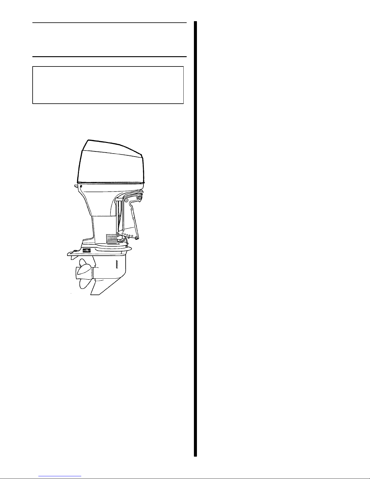
FORCE 75/90/120 MODELS
INSTALLATION MANUAL
NOTICE to INSTALLER
After Completing Installation, These Instructions Should Be Placed with the Product for
the Owner’s Future Use.
75/90/120 Model
This installation manual provides outboard installation procedure, proper setup and necessary adjustments. PLEASE READ CAREFULLY AND THOROUGHLY BEFORE BEGINNING INSTALLATION.
The remote control connected to your outboard
MUST be equipped with a start-in-gear protection device. This p r events the engine from starting when the
outboard is in gear.
1998 Mercury Marine
The following are registered trademarks of Brunswick Corporation: Autoblend, Force, Jet-Prop, Mariner, Merc, MerCathode,
MerCruiser, Mercury, Mercury Marine, Quicksilver, Ride-Guide,
Sport-Jet, and Thruster.
Table of Contents
Page
Notice to Installer and Owner 2. . . . . . . . . . . . . . . . .
Selecting Steering Cables and
Remote Control Cables 2. . . . . . . . . . . . . . . . . . . .
Installing Outboard on Transom 2. . . . . . . . . . . . . . .
Determining Recommended
Outboard Mounting Height 2. . . . . . . . . . . . . .
Locating Centerline of Boat Transom 2. . . . . . .
Drilling Outboard Mounting Holes 3. . . . . . . . . .
Lifting Outboard 3. . . . . . . . . . . . . . . . . . . . . . . . .
Securing Outboard to Boat Transom 3. . . . . . . .
Ride Guide Steering Cable/Attaching
Kit Installation 4. . . . . . . . . . . . . . . . . . . . . . . . . . . . .
Installing Ride Guide Steering
Cable To The Outboard 4. . . . . . . . . . . . . . . . .
Steering Link Rod Installation 4. . . . . . . . . . . . . .
Lubrication 5. . . . . . . . . . . . . . . . . . . . . . . . . . . . . .
Remote Control Installation 5. . . . . . . . . . . . . . . . . . .
Shift and Throttle Cable
Installation to the Outboard 6. . . . . . . . . . . . . . . . .
Shift Cable Installation 6. . . . . . . . . . . . . . . . . . . .
Throttle Cable Installation 6. . . . . . . . . . . . . . . . .
Fuel Line Installation 7. . . . . . . . . . . . . . . . . . . . . . . . .
Fuel Line 7. . . . . . . . . . . . . . . . . . . . . . . . . . . . . . .
Portable Fuel Tank 8. . . . . . . . . . . . . . . . . . . . . . .
Permanent Fuel Tank 8. . . . . . . . . . . . . . . . . . . . .
Required Side Mount Remote Control
or Ignition Key Switch Assembly 8. . . . . . . . . . . . .
Boats Equipped with Side Mount
Remote Control 8. . . . . . . . . . . . . . . . . . . . . . . .
Boats equipped with Panel
or Console Mount Remote Control 8. . . . . . .
Connecting Remote Control or Key Switch Wire
Harness to Engine Wire Harness 8. . . . . . . . . . . .
Battery Connections 9. . . . . . . . . . . . . . . . . . . . . . . . .
Propeller Selection 9. . . . . . . . . . . . . . . . . . . . . . . . . .
Propeller Installation 9. . . . . . . . . . . . . . . . . . . . . . . . .
Power Trim System 10. . . . . . . . . . . . . . . . . . . . . . . . .
General Information 10. . . . . . . . . . . . . . . . . . . . .
Power Trim Operation 10. . . . . . . . . . . . . . . . . . .
Trim “In” Angle Adjustment
(Models With Power Trim) 11. . . . . . . . . . . . . .
Checking Power Trim Fluid Level 11. . . . . . . . .
Tilt Pin Adjustment
(Models Without Power Trim) 11. . . . . . . . . . . . . .
Trim Tab Adjustment 12. . . . . . . . . . . . . . . . . . . . . . . .
Boat Performance 13. . . . . . . . . . . . . . . . . . . . . . . . . .
Test Instructions 13. . . . . . . . . . . . . . . . . . . . . . . .
90-826881990 398- 1 -Printed in U.S.A.
Page 2
Notice to Installer and Owner
Installing Outboard on
This manual as well as safety labels posted on the
outboard use the following safety alerts to draw your
attention to special safety instructions that should be
followed.
!
DANGER
DANGER - Immediate hazards which WILL result
in severe personal injury or death.
!
WARNING
WARNING - Hazards or unsafe practices which
COULD result in severe personal injury or death.
CAUTION
CAUTION - Hazards or unsafe practices which
could result in minor personal injury or product
or property damage.
!
WARNING
DO NOT OVERPOWER - Most boats are rated and
certified for the maximum horsepower capabilities of the boat. Refer to the boat’s “Certification
Plate” for the maximum horsepower limit or, if in
doubt, contact your dealer or boat manufacturer.
Transom
Determining Recommended
Outboard Mounting Height
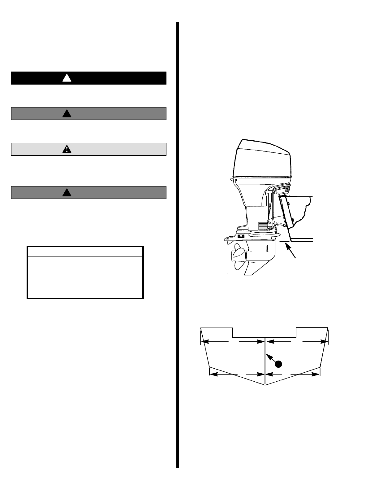
Long drive shaft housing models are designed to operate on boats that have a 20 inch transom (51 cm).
X-Long drive shaft housing models are designed to
operate on boats that have a 25 inch transom (64 cm).
For best all-around boating performance, it is recommended that the outboard be mounted with the
anti-ventilation plate flush with the boat bottom.
U.S. COAST GUARD CAPACITY
MAXIMUM HORSEPOWER XXX
MAXIMUM PERSON
CAPACITY (POUNDS) XXX
MAXIMUM WEIGHT
CAPACITY XXX
Selecting Steering Cables
and Remote Control Cables
Refer to “Quicksilver Accessories Guide” to determine correct length of steering cables and remote
control cables.
IMPORTANT: Steering cables and remote control
cables must be the correct length. Sharp bends
on too-short cables result in “kinks;” too-long
cables require unnecessary bends and/or loops.
Both conditions place extra stress on the cables.
Locating Centerline of Boat Transom
Locate (and mark with pencil) vertical centerline (a)
of boat transom.
BA
a
DC
a - Centerline of Transom
NOTE: Dimensions “A” = “B” and “C” = “D”.
- 2 -
Page 3
Drilling Outboard Mounting Holes
Lifting Outboard
IMPORT ANT: Before drilling any mounting holes,
carefully read “Determining Recommended Outboard Mounting Height,” preceding. There is a 3/4
in. (19 mm) difference between outboard mounting holes in transom brackets.
!
WARNING
DO NOT, under any circumstances, allow upper
outboard mounting bolts to be closer than 1 in.
(25.4 mm) from top of boat transom. Upper
mounting bolts must never be installed thru
shims.
NOTE: When drilling into a fiberglass boat, place
masking tape directly onto boat where mounting
holes will be drilled to help prevent fiberglass from
chipping.
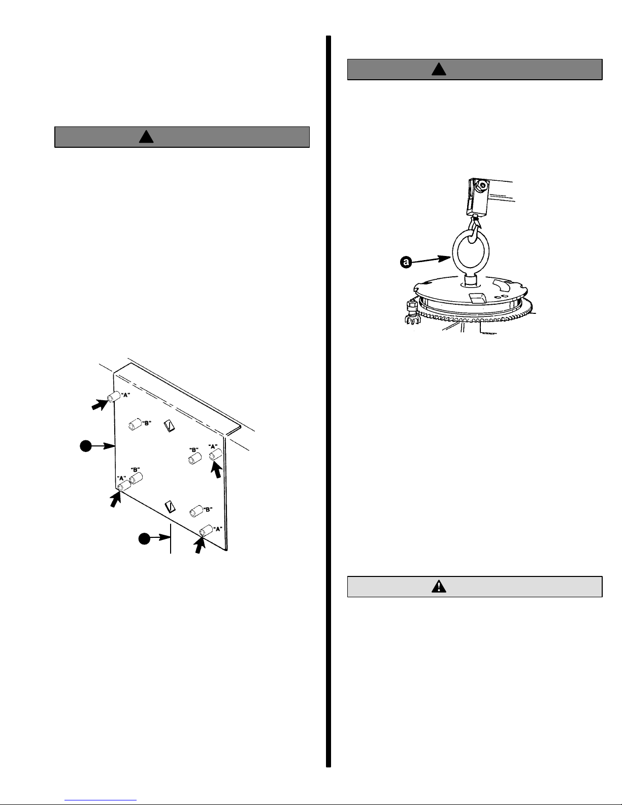
IMPORTANT: When using “Transom Drilling Fixture” (part number 91-98234A2), use drill guide
holes marked “A” when drilling outboard mounting holes.
!
WARNING
Make sure lifting ring is threaded on flywheel a
minimum of 5 turns and that hoist has a maximum
lift capacity over 500 lbs. (227 kg) BEFORE lifting
outboard.
Remove top cowl from outboard. Thread lifting ring
(a) on flywheel a minimum of 5 turns.
a - Lifting Ring (91-90455)
b
a
a - Centerline of Transom
b - Transom Drilling Fixture (91-98234A2)
1. Use a 17/32 in. (13.5 mm) diameter drill bit to drill
4 mounting holes perpendicular to and thru transom.
Connect hoist [maximum lifting capacity over 500 lbs.
(227 kg)] to lifting ring and lift outboard onto boat transom.
Securing Outboard to Boat Transom
IMPORT ANT: I f boat is equipped with thru tilt tube
steering, steering cable end must be installed
into tilt tube of outboard before securing outboard to transom. Refer to “Steering Cable and
Steering Link Rod Installation” following.
Position outboard on boat transom to align mounting
holes in transom brackets with those drilled in boat
that will place the outboard at the recommended
mounting height (refer to “Determining Recommended Outboard Mounting Height,” preceding).
CAUTION
Marine sealer must be used on shanks of mounting bolts (not threads) to make a water-tight installation.
IMPORT ANT: DO NOT use an impact driver when
tightening transom mounting bolts.
Apply marine sealer to shanks of mounting bolts (not
threads). Secure outboard to transom using four (4)
bolts, flat washers and locknuts, as shown. Be sure
installation is water-tight.
- 3 -
Page 4
!
WARNING
Before operating, outboard(s) MUST BE SECURED to boat transom with four 1/2 in. diameter
bolts, flat washers and locknuts (supplied) as follows: two (2) bolts must be installed thru upper
mounting holes and two (2) bolts thru lower
mounting holes. Installation must be water-tight
and outboard should be checked for tightness on
transom during operation. Failure to bolt outboard to transom as described may result in damage to the boat and/or loss of outboard and possible injury to occupants of boat.
Installing Ride Guide Steering Cable
To The Outboard
IMPORTANT: Before installing steering cable in
tilt tube, lubricate entire cable end with Quicksilver 2-4-C Marine Lubricant.
NOTE: Ride Guide steering cable is lubricated at the
factory and requires no additional lubrication at initial
installation.
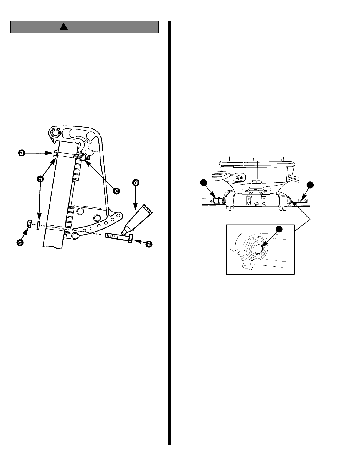
1. Lubricate seal (a) inside of outboard tilt tube and
entire cable end (b) with Quicksilver 2-4-C Marine
Lubricant.
2. Insert steering cable end thru outboard tilt tube
and secure steering cable to tilt tube with steering
cable attaching nut (c), as shown. Torque nut to
35 lb. ft. (47.5 N·m).
a - 1/2 Inch Diameter Bolts
b - Flat Washers
c - Locknuts
d - Marine Sealer
Ride Guide Steering Cable/
Attaching Kit Installation
NOTE: These instructions are for single cable-single
outboard installations. Instructions for mounting dual
engines are included with the applicable dual engine
attaching kit. Refer to “Quicksilver Accessories
Guide” to determine correct kit.
Refer to “Quicksilver Accessories Guide” to determine correct length of steering cable.
IMPORTANT: Steering cable must be correct
length. Sharp bends on too-short of a cable result
in “kinks;” too-long of a cable requires unnecessary bends and/or loops. Both conditions place
extra stress on the cable.
Install steering mount and steering wheel in accordance with installation instructions that accompany
each.
c
a
b
Steering Link Rod Installation
IMPORTANT: The steering link rod that connects
the steering cable to the engine must be fastened
using special washer head bolt (“a” – Part Number 10-14000) and self locking nuts (“b” & “c” –
Part Number 11-34863). These locknuts must
never be replaced with common nuts (non locking) as they will work loose and vibrate off freeing
the link rod to disengage.
IMPORTANT: Disengagement of a steering link
rod can result in the boat taking a full, sudden,
sharp turn. This potentially violent action can
cause occupants to be thrown overboard exposing them to serious injury or death.
3. Assemble steering link rod to steering cable with
two flat washers (d) and nylon insert locknut (“b”
– Part Number 1 1-34863). T ighten locknut (b) until it seats, then back nut off 1/4 turn.
- 4 -
Page 5
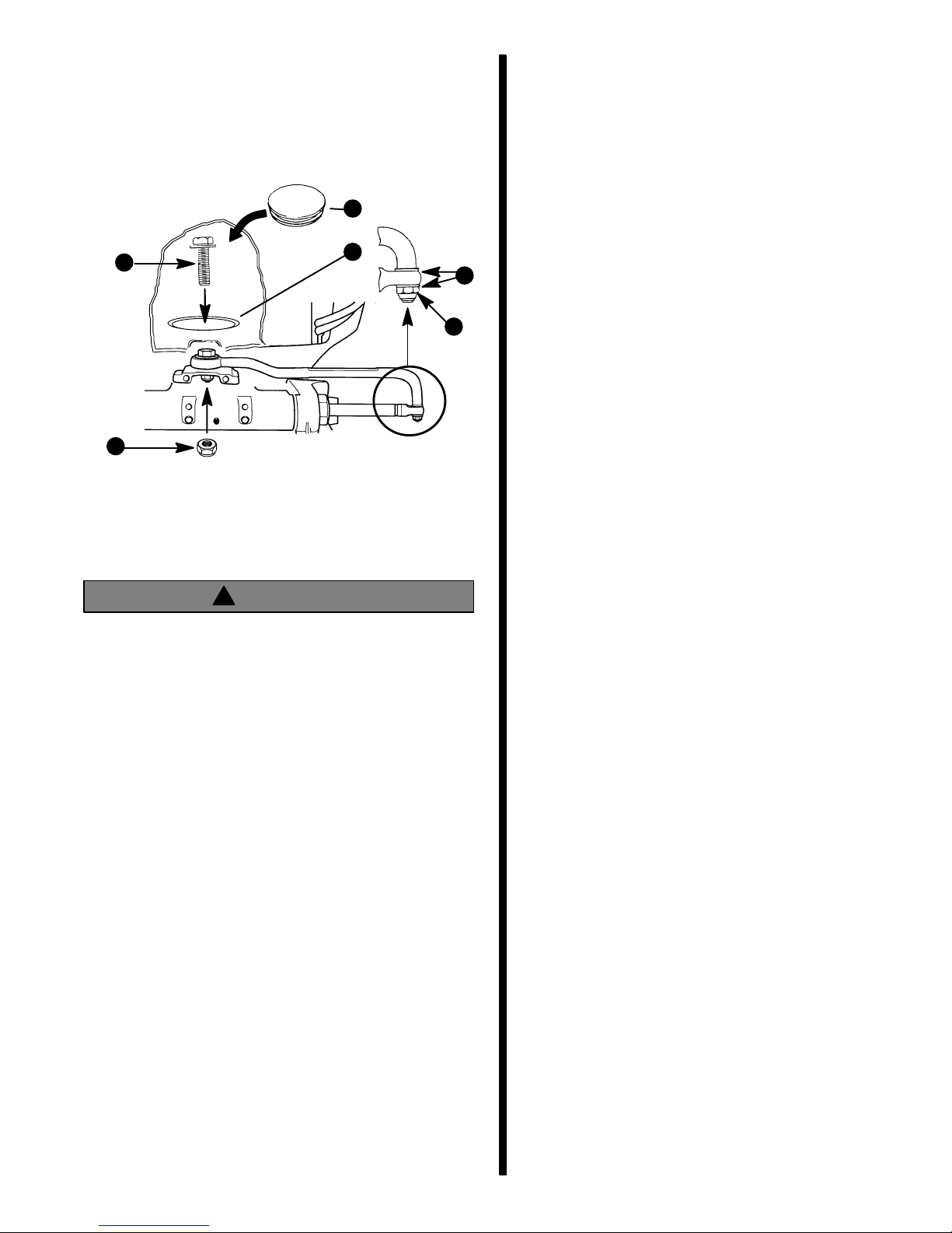
4. Assemble steering link rod to engine with special
washer head bolt (“a” – Part Number 10-14000)
and nylon insert locknut (“c” – Part Number
11-34863). First torque bolt (a) to 20 lb. ft. (27.1
N·m), then torque locknut (c) to 20 lb. ft. (27.1
N·m). Install access hole plug in bottom cowl.
e
a
f
d
b
c
a - Head Bolt
b - Locknut
c - Nylon Insert Locknut
d - Flat Washers
e - Access Hole Plug
f - Access Hole (located in bottom cowl)
Remote Control Installation
Refer to “Quicksilver Accessories Guide” to determine correct length of remote control cables.
IMPORT ANT: R e m ote control cables must be correct length. Sharp bends on too-short cables result in “kinks;” too-long cables require unnecessary bends and/or loops. Both conditions place
extra stress on the cables.
IMPORTANT: Install control cables to remote control and mount remote control BEFORE attaching
control cables to engine. Refer to installation instructions included with remote control.
!
WARNING
After installation is complete (and before operating outboard), check that boat will turn right when
steering wheel is turned right and that boat will
turn left when steering wheel is turned left. Check
steering thru full range (left and right) and at all tilt
angles to assure interference-free movement.
Lubrication
Lubrication and maintenance inspection of the steering system is the owners responsibility. I t must be performed every 60 days in fresh water or 30 days in salt
water.
Refer to operators manual for correct lubrication and
maintenance procedure.
- 5 -
Page 6
Shift and Throttle Cable
Installation to the Outboard
Install the shift cable and throttle cable into the remote
control and mount the remote control following
instructions which are provided with remote control.
NOTE: Install the shift cable before the throttle cable.
The shift cable is the first cable to move when the remote control handle is actuated.
Shift Cable Installation
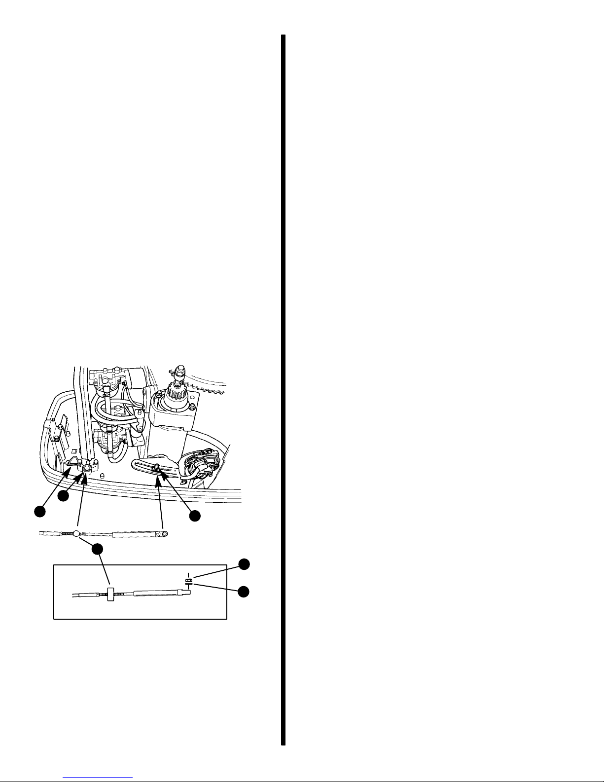
1. Position the remote control handle into neutral
detent.
2. Manually shift engine (move shift actuator “a”)
into neutral position. The propeller shaft can rotate in either direction.
3. Slide shift actuator (a) toward the rear of engine
(reverse gear) until resistance is felt. Measure the
distance between mounting stud and barrel retainer. Push the cable end in (towards cable barrel) until resistance is felt. Adjust the cable barrel
to obtain the proper distance.
4. Place the s h ift cable barrel into the barrel retainer
and the cable end on the cable mounting stud.
Fasten shift cable to the mounting stud with nylon
washer (e) and locknut (d). Tighten locknut
against the nylon washer, then back-off the locknut 1/4 turn. Lock cable barrel (c) in barrel retainer
(b) with retainer latch (f).
5. Check shift cable adjustments as follows:
a. With remote control in forward the propshaft
should lock solidly in gear. If it does not, adjust
the cable barrel closer to the cable end guide.
b. Shift remote control into neutral. The prop-
shaft should turn freely without drag. If not,
adjust the barrel away from the cable end
guide. Repeat steps a and b.
c. Shift remote control into reverse while turning
propeller. The propshaft should lock solidly in
gear. If not, adjust the barrel away from the
cable end guide. Repeat steps a thru c.
d. Return remote control handle to neutral. The
propeller should turn freely without drag. If
not, adjust the barrel closer to the cable end
guide. Repeat steps a thru d.
b
f
c
a - Shift Actuator
b - Barrel Retainer
c - Cable Barrel
d - Locknut
e - Nylon Washer
f - Barrel Retainer Latch
Throttle Cable Installation
NOTE: Attach SHIFT CABLE to engine prior to at-
taching THROTTLE CABLE.
1. Position remote control handle in neutral detent.
2. Position engine throttle lever against idle stop.
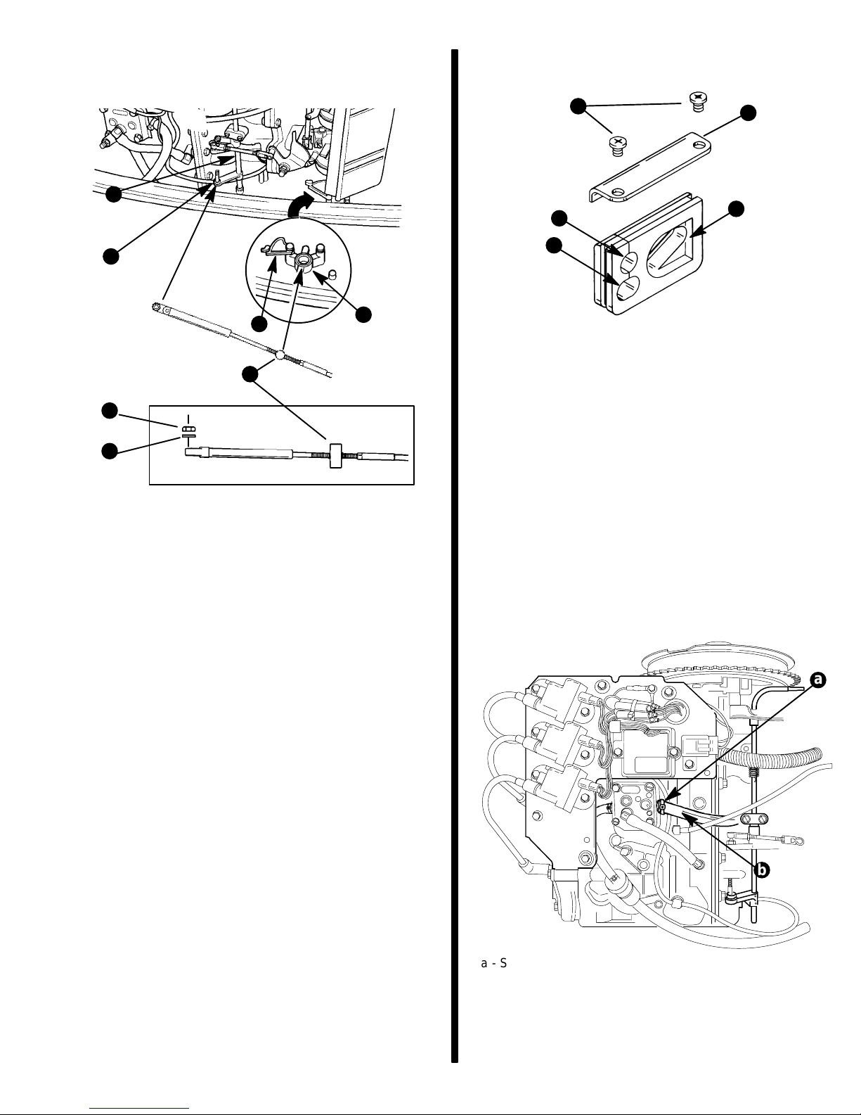
3. Measure distance between throttle barrel retainer
(a) and throttle actuator stud (b) (center-to-center). Add 1/8 in. (3.18 mm) for preload.
a
d
e
4. Adjust cable barrel (c) to attain the same distance
between barrel and hole in throttle cable end
guide (center-to-center) as measured in step 3.
5. Place the throttle cable barrel into barrel retainer
and the cable end on the cable mounting stud.
Fasten throttle cable to the mounting stud with nylon washer (e) and locknut (d). Tighten locknut
against the nylon washer, then back-off the lock
nut 1/4 turn. Lock cable barrel (c) in barrel retainer
(a) with retainer latch (g).
6. Check throttle cable adjustment as follows:
a. Advance remote control to wide open throttle
and bring back to neutral.
b. Manually push tower shaft (f) towards idle
stop. If tower shaft moves toward stop, adjust
cable barrel away from cable end guide. Repeat steps a and b.
- 6 -
Page 7
NOTE: There should be some preload on throttle
cable to ensure throttle will return to full idle when in
neutral.
9. Install grommet in bottom cowl. Secure with retainer (e) and screws (d).
d
e
f
b
g
a
c
d
e
a - Barrel Retainer
b - Throttle Cable Mounting Stud
c - Cable Barrel
d - Locknut
e - Nylon Washer
f - Throttle Shaft
g - Barrel Retainer Latch
7. Route throttle cable through grommet opening
(a).
a
c
b
Starboard
Bottom Cowl Grommet
a - Opening for Power Trim Wire Harness
b - Opening for Throttle Cable
c - Opening for Fuel Connector
d - Screws
e - Retainer
Fuel Line Installation
Fuel Line
Minimum fuel line inside diameter (I.D.) is 5/16 in. (8
mm) with separate fuel line/fuel tank pickup for each
engine.
1. Install fuel line on fuel pump, secure with a stastrap (a).
8. Route power trim wire harness through grommet
opening (b).
a
b
a - Sta-Strap
b - Inlet Fuel Line
2. Insert fuel connector into bottom cowl grommet.
Install bolt and tighten securely.
- 7 -
Page 8
Portable Fuel Tank
Connecting Remote Control
Select a suitable location in boat within engine fuel
line length limitations and secure tank in place.
Permanent Fuel Tank
Permanent fuel tanks should be installed in accordance with industry and federal safety standards
which include recommendations applicable to
grounding, anti-siphon protection, ventilation, etc.
Required Side Mount Remote
Control or Ignition Key
Switch Assembly
Boats Equipped with Side Mount
Remote Control
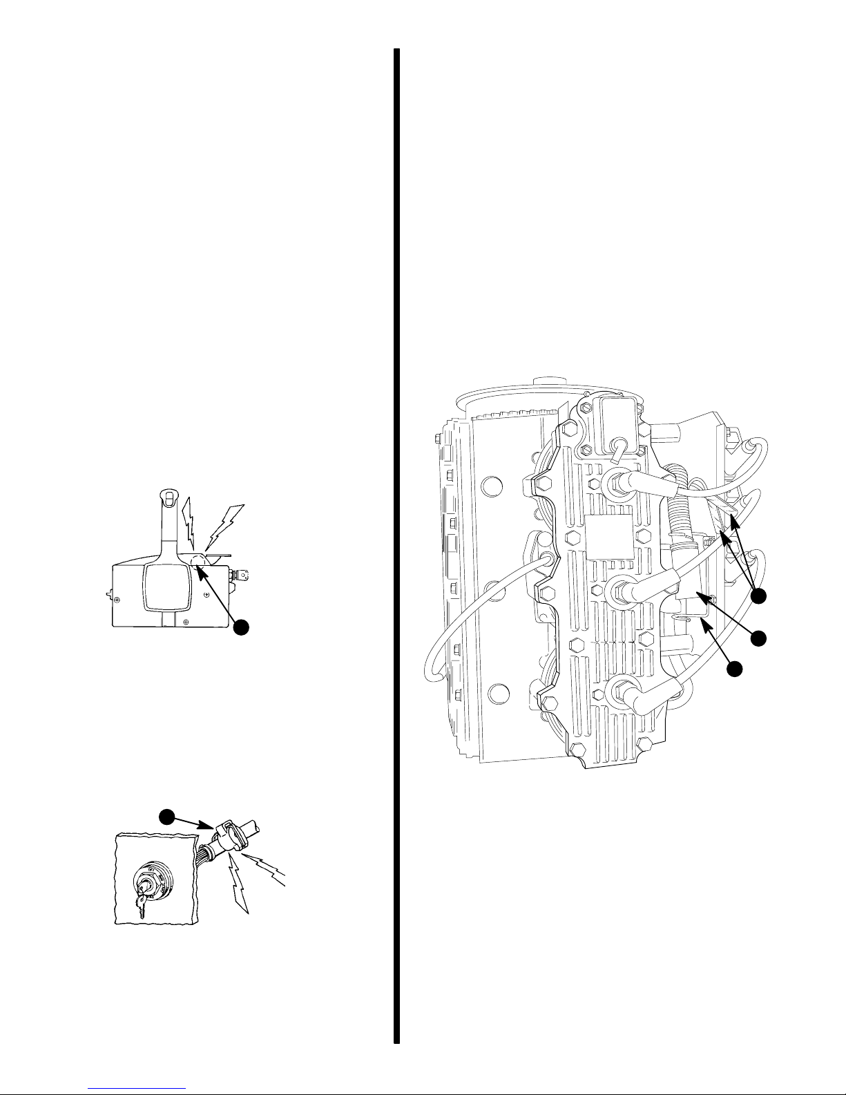
A Quicksilver Commander 2000 series Side Mount
Remote Control equipped with a warning horn must
be used with this outboard. This warning horn is necessary for the engine overheat warning system.
or Key Switch Wire Harness
to Engine Wire Harness
1. Route remote control harness or key switch harness down side of boat to outboard, fastening
harness to boat. Be sure harness does not rub,
get pinched or come in contact with bilge water.
2. Route harness thru cowl. Plug remote harness
connector into engine harness connector and secure in place with harness clamp.
3. If outboard is equipped with power trim, connect
blue and green wires from remote harness to respective leads in engine harness (isolate brown/
white and tan wires as these are used for accessories).
a
a - Warning Horn
Boats equipped with Panel or
Console Mount Remote Control
A Quicksilver Ignition Key/Choke Assembly equipped
with a warning horn must be used with this engine.
This warning horn is necessary for the engine overheat warning system.
a
a - Warning Horn
b
a
c
53759
a - Engine Harness Connector
b - Power Trim Wires
c - Harness Clamp
- 8 -
Page 9
4. Check that harness has enough slack to allow
outboard to operate throughout its full steering
and tilt ranges.
5. Place shift cable, battery cable, and remote control wire ha r ness in openings in grommet. Secure
grommet in bottom cowl with retainer and screws.
For best all around performance from your outboard/
boat combination, select a propeller that allows the
engine to operate in the upper half of the recommended full t h r o ttle RPM range with the boat normally
loaded (refer to Specifications in the Operators Manual). This RPM range allows for better acceleration
while maintaining maximum boat speed.
If changing conditions cause the RPM to drop below
the recommended range (such as warmer, more
humid weather, operation at higher elevations, increased boat load or a dirty boat bottom/gear case)
this may require a propeller change or cleaning to
maintain performance and ensure the outboard’s
durability.
Check full-throttle RPM using an accurate tachometer with the engine trimmed out to a balanced steering
condition (steering effort equal in both directions)
without causing the propeller to “break loose.”
Port
Bottom Cowl Grommet
a - Opening for Battery Cable
b - Opening for Control Harness
c - Opening for shift cable
d - Retainer
e - Screws
Battery Connections
CAUTION
Failure to observe correct polarity when connecting battery cables to battery will result in damage
to the charging system.
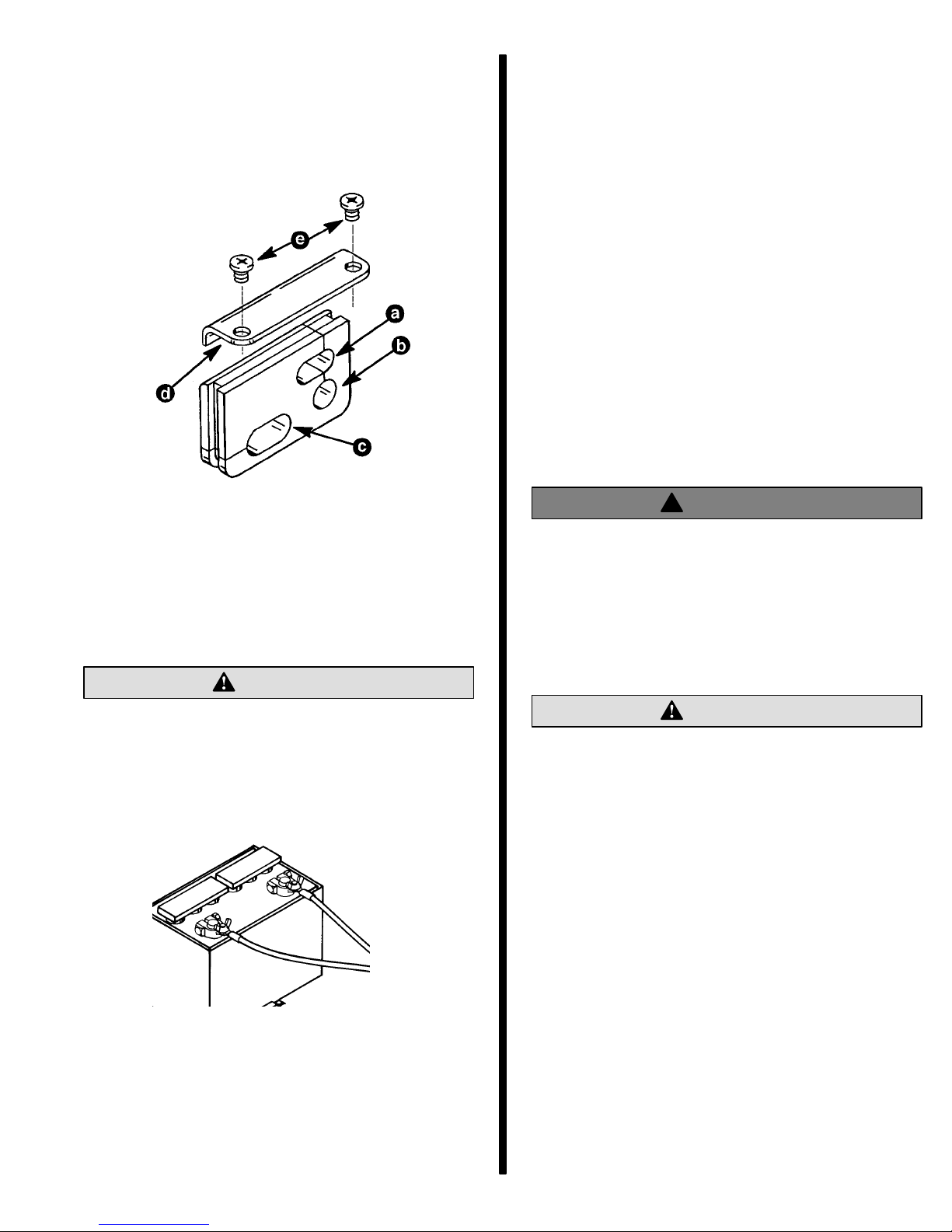
Connect battery cables from engine to battery. Connect red battery cable to positive battery terminal and
black battery cable to negative battery terminal.
(–)
(+)
Propeller Selection
Refer to “Quicksilver Accessory Guide” for a complete list of available propellers.
Propeller Installation
!
WARNING
When the propeller shaft is rotated and the engine is in gear, there is the possibility for the engine to crank over and start. T o prevent this type
of accidental engine starting and possible serious injury caused from being struck by a rotating
propeller, always set the remote control into neutral and remove spark plug leads when you are
servicing the propeller.
CAUTION
If the propeller moves forward-and-aft on the propeller shaft (is loose), retighten the propeller nut.
Operation with a loose propeller could cause
damage to the thrust hub and gear housing during acceleration, deceleration or when shifting
gears.
IMPORT ANT: To assure that the propeller remains
secure on the shaft during the season, periodically check propeller locknut for tightness.
To prevent the propeller hub from corroding and seizing to the propeller shaft, especially in salt water, always apply a coat of Quicksilver Anti-Corrosion
Grease to the entire shaft at recommended maintenance intervals and each time the propeller is removed.
1. Shift remote control into neutral position.
2. Remove leads from spark plugs to prevent engine
from starting.
- 9 -
Page 10
3. Apply Quicksilver Anti-Corrosion Grease to entire
shaft.
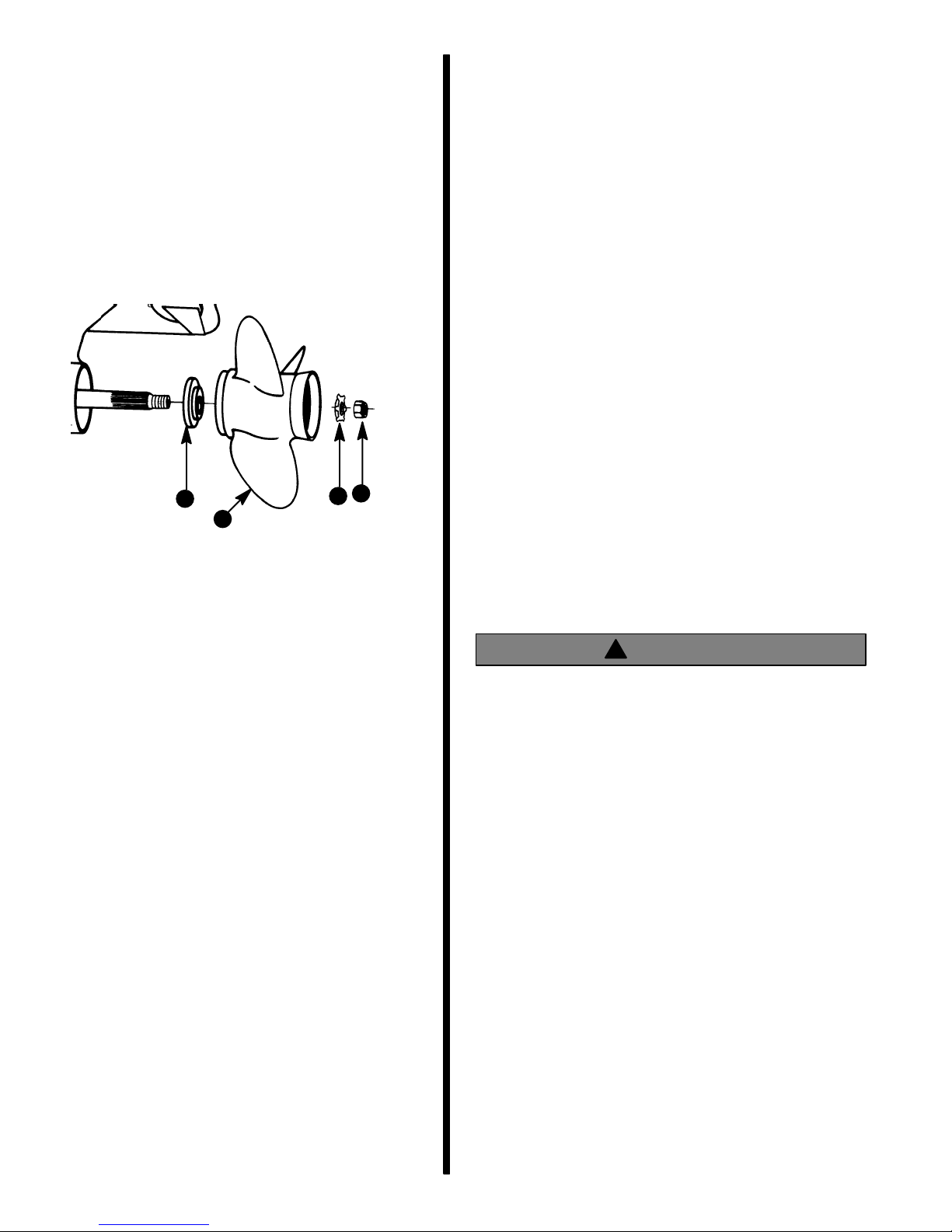
4. Install thrust washer (a), propeller (b), propeller
nut retainer (c), and propeller nut (d) onto the
shaft.
5. Place a block of wood between gear case and
propeller and torque propeller locknut to 55 lb. ft.
(75 N·m), aligning tabs of washer with flat grooves
of propeller hub.
6. Secure propeller nut by bending three of the tabs
into the thrust hub grooves.
d
a
b
a - Thrust Washer
b - Propeller
c - Propeller Nut Retainer
d - Propeller Nut
c
IMPORTANT: Avoid possible serious injury or
death. When the outboard is trimmed in or out beyond a neutral steering condition, a pull on the
steering wheel or tiller handle in either direction
may result. Failure to keep a continuous firm grip
on the steering wheel or tiller handle when this
condition exists can result in loss of boat control
as the outboard can turn freely. The boat can now
“spin out” or go into a very tight maximum turn
which, if unexpected, can result in occupants being thrown within the boat or out of the boat.
Consider the following lists carefully.
TRIMMING IN OR DOWN CAN:
1. Lower the bow.
2. Result in quicker planing off, especially with a
heavy load or a stern heavy boat.
3. Generally improve the ride in choppy water.
4. Increase steering torque or pull to the right (with
the normal right hand rotation propeller).
5. In excess, lower the bow of some boats to a point
where they begin to plow with their bow in the water while on plane. This can result in an unexpected turn in either direction called “bow steering”
or “over steering” if any turn is attempted or if a significant wave is encountered.
Power Trim System
General Information
The power trim system is filled at the manufacturer
and is ready for use.
Trim outboard through entire trim and tilt range several times to remove any air from the system.
The trim system is pressurized and is not externally
vented.
Power Trim Operation
With most boats, operating around the middle of the
“trim” range will give satisfactory results. However, to
take full advantage of the trimming capability there
may be times when you choose to trim your outboard
all the way in or out. Along with an improvement in
some performance aspects comes a greater responsibility for the operator, and this is being aware of
some potential control hazards. The most significant
control hazard is a pull or “torque” that can be felt on
the steering wheel or tiller handle. This steering
torque results from the outboard being trimmed so
that the propeller shaft is not parallel to the water surface.
!
WARNING
Avoid possible serious injury or death. Adjust
outboard to a n intermediate trim position as soon
as boat is on plane to avoid possible ejection due
to boat spin-out. Do not attempt to turn boat when
on plane if outboard is trimmed extremely in or
down and there is a pull on the steering wheel or
tiller handle.
TRIMMING OUT OR UP CAN:
1. Lift the bow higher out of the water.
2. Generally increase top speed.
3. Increase clearance over submerged objects or a
shallow bottom.
4. Increase steering torque or pull to the left at a normal installation height (with the normal right hand
rotation propeller).
5. In excess, cause boat “porpoising” (bouncing) or
propeller ventilation.
6. Cause engine overheating if any water intake
holes are above the water line.
- 10 -
Page 11
Trim “In” Angle Adjustment (Models
With Power Trim)
Some outboard boats, particularly some bass boats,
are built with a greater than normal transom angle
which will allow the outboard to be trimmed further “in”
or “under”. This greater trim “under” capability is desirable to improve acceleration, reduce the angle and
time spend in a bow high boat attitude during planing
off, and in some cases, may be necessary to plane off
a boat with aft live wells, given the variety of available
propellers and height range of engine installations.
However, once on plane, the engine should be
trimmed to a more intermediate position to a avoid a
bow-down planing condition called “plowing”. Plowing can cause “bow steering” or “over steering” and
inefficiently consumes horsepower. In this condition,
if attempting a turn or encountering a diagonal, moderate wake, a more abrupt turn than intended may result.
In rare circumstances, the owner may decide to limit
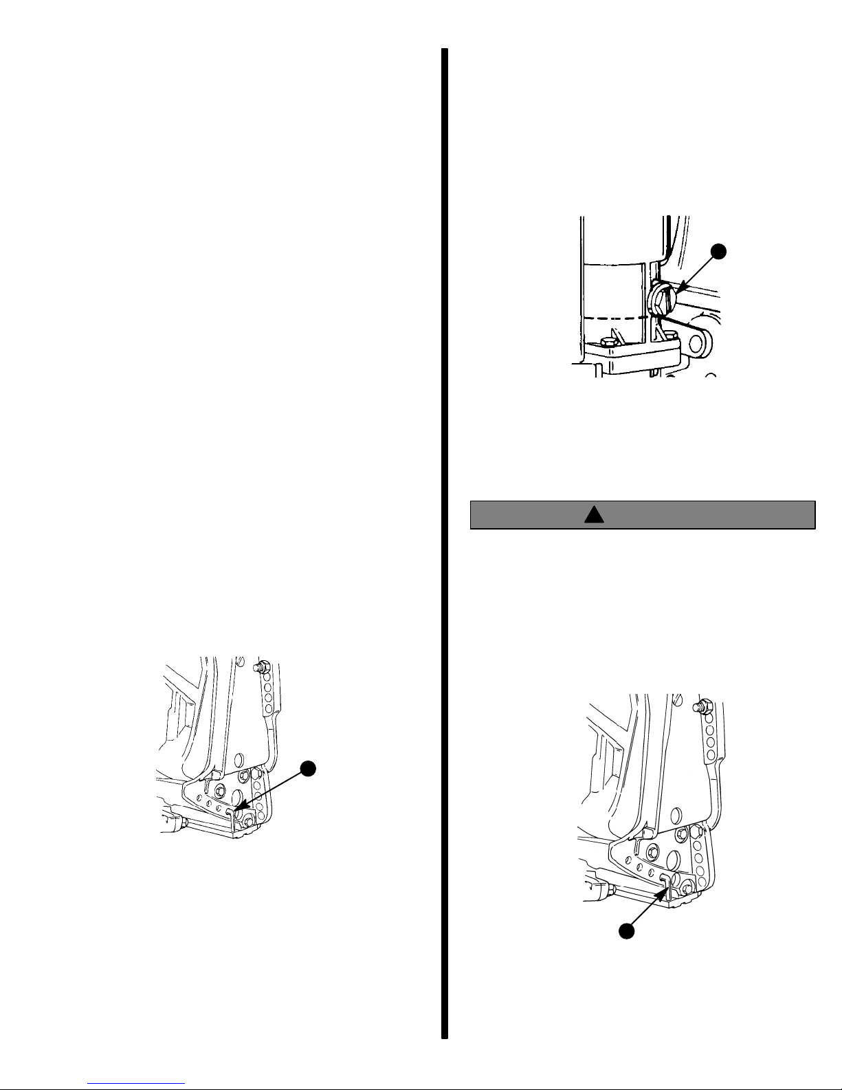
the trim under. This can be accomplished by purchasing a stainless steel tilt pin (P/N 17-49930A1) and inserting it through whatever pin hole is desired. The
non-stainless steel shipping bolt should not be used
in this application other than on a temporary basis.
IMPORTANT: Avoid possible serious injury or
death. Adjust outboard to an intermediate trim
position as soon as boat is on plane to avoid possible ejection due to boat spin-out. Do not attempt to turn boat when on plane if outboard is
trimmed extremely in or down and there is a pull
on the steering wheel or tiller handle.
Checking Power Trim Fluid Level
1. Tilt outboard to the full up position and engage the
tilt support lever.
2. Remove fill cap and check fluid level. The fluid
level should be even with the bottom of the fill
hole. If necessary, add Quicksilver Power Trim &
Steering Fluid or automotive transmission fluid
(ATF) Type F, FA or Dexron II.
a
a - Fill Cap
Tilt Pin Adjustment (Models
Without Power Trim)
!
WARNING
DO NOT operate boat without the tilt pin installed.
Failure to install tilt pin could result in outboard
kicking up when operated in reverse causing serious injury, death, or property damage.
Place tilt pin in desired hole in the transom bracket so
the outboard will run perpendicular to the water when
the boat is running at full speed. This allows the boat
to be driven parallel to the water.
a - Stainless Steel Tilt Pin (P/N 17-49930A1)
a
a
a - Tilt Pin
Consider the following lists carefully when adjusting
the tilt pin.
- 11 -
Page 12
PLACING TILT PIN IN LOWER HOLES CAN:
MODELS WITHOUT POWER TRIM
1. Lower the bow.
2. Result in quicker planing off, especially with a
heavy load or a stern heavy boat.
3. Generally improve the ride in choppy water.
4. Increase steering torque or pull to the right (with
the normal right hand rotation propeller).
5. In excess, lower the bow of some boats to a point
where they begin to plow with their bow in the water while on plane. This can result in an unexpected turn in either direction called “bow steering” or “over steering” if any turn is attempted or
if a significant wave is encountered.
PLACING TILT PIN IN UPPER HOLES CAN:
1. Lift the bow out of the water.
2. Generally increase top speed.
3. Increase clearance over submerged objects or a
shallow bottom.
4. Increase steering torque or pull to the left at a normal installation height (with the normal right hand
rotation propeller).
Operate your boat at normal cruising speed trimmed
to desired position by installing the “tilt pin” in the desired tilt pin hole. Turn your boat left and right and note
the direction the boat turns more easily.
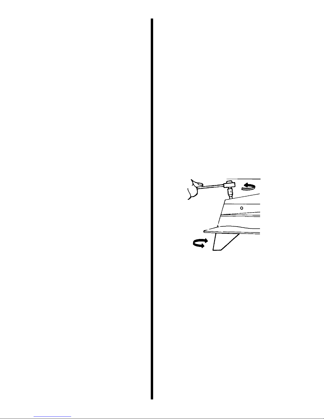
If adjustment is necessary, loosen trim tab bolt and
make small adjustments at a time. If the boat turns
more easily to the left, move the trailing edge of trim
tab to the left. If the boat turns more easily to the right
move the trailing edge of trim tab to the right. Retighten bolt and retest.
MODELS WITH POWER TRIM
Operate your boat at normal cruising speed, trimmed
to desired position. Turn your boat left and right and
note the direction the boat turns more easily.
If adjustment is necessary, loosen trim tab bolt and
make small adjustments at a time. If the boat turns
more easily to the left, move the trailing edge of trim
tab to the left. If the boat turns more easily to the right
move the trailing edge of trim tab to the right. Retighten bolt and retest.
5. In excess, cause boat “porpoising” (bouncing) or
propeller ventilation.
Trim Tab Adjustment
Propeller steering torque will cause your boat to pull
in one direction. This steering torque is a normal thing
that results from your outboard not being trimmed so
the propeller shaft is parallel to the wa ter sur fac e. The
trim tab can help to compensate for this steering
torque in many cases and can be adjusted within limits to reduce any unequal steering effort.
NOTE: Trim tab adjustment will have little effect reducing steering torque if the outboard is installed w ith
the anti-ventilation plate approximately 2 inches
(50mm) or more above the boat bottom.
- 12 -
Page 13
Boat Performance
Test Instructions
IMPORTANT: A tight grip on the steering wheel/
tiller handle is always advisable when accelerating, decelerating, or when trimming the boat. On
models with Power Trim, upon reaching cruising
speed, the outboard should be trimmed to obtain
a balanced steering condition. While trimming,
steering loads will vary and will pull in one
direction until a balanced steering condition is
obtained. If the outboard is trimmed past the
balanced steering condition, the steering wheel/
tiller handle then will have a tendency to pull in
the opposite direction. Excessive trimming past
the balanced steering position will result in
increased steering loads, and, in most boat
applications, a decrease in performance.
NOTE: When performing an acceleration test, it is
recommended that a stop watch be used to improve
testing accuracy. A wrist watch with a second hand
may be substituted.
5. An acceleration test can also be performed if desired. Start the test with boat motionless in the water and outboard in neutral. A stop watch should
be started as the throttle is quickly pushed to
WOT (wide open throttle). Stop the watch as the
speedometer needle sweeps past 20 MPH (32
km/hr). Several runs should be made to assure a
good average.
6. Prop “break loose” (sudden high RPM), if not excessive, in some cases can be beneficial during
acceleration. If undesirable “break loose” occurs,
it can be decreased by trimming the outboard further under. If it remains excessive with all similar
propellers, the outboard must be lowered.
CAUTION
When trimming a boat with dual outboards, both
outboards should be at approximately the same
tilt angle and be tilted out (up) simultaneously (to
prevent boat from pitching side-to-side) until desired boat attitude is achieved. Outboards can
then be trimmed individually to precisely adjust
boat trim angle and pitch.
1. With boat in water, trim the outboard(s) (trim button in remote control handle) so that the decal on
the side cowl is horizontal. This is a typical setting
that should give reasonable acceleration and top
speed.
2. Go for a short familiarization ride at various
throttle and trim settings BEFORE starting testing.
3. When making either top speed or acceleration
runs, best accuracy will be obtained by running
with or against any wind. Side winds require driving in a constant turn to keep the boat running
straight-ahead. If winds are 10 MPH (16 km/hr) or
greater, it is suggested that all acceleration runs
be made down wind.
7. It is suggested that all applicable data be recorded on a chart and retained for future reference.
8. After several propellers of different pitch and/or
design have been tried, select one that best services the general purpose of the boat. The selected propeller should enable the engine to operate within its recommended full throttle RPM
range, without excessive propeller “break loose”
during acceleration or turns. A second propeller,
which would make both a suitable spare or a special purpose alternate, might also be desirable.
NOTE: A higher pitch often gives better top speed,
but the next lower pitch gives adequate top speed
with much better acceleration.
4. The top speed WOT (wide open throttle) test
should be done with the boat normally loaded (to
duplicate actual running conditions). Operate
boat in gear at WOT and check RPM. Engine
RPM must be within the recommended full
throttle RPM range (listed in Operation and Maintenance Manual).
- 13 -
Page 14

 Loading...