

Page 1
OPERATION MANUAL
VARIABLE FRAME RATE CAMERA
VFC-1000
(1ST EDITION)
FOR-A COMPANY LIMITED
Page 2

Page 3

Page 4

Page 5

Notice To User
FOR-A software programs and manuals contain copyrighted material, which is the sole
property of FOR-A Co. Ltd. And the following terms apply to the end user.
Manual and / or product related information furnished by FOR-A is intended solely to
provide operation and / or service instructions for equipment and / or software
accompanying it. It may not be used or reproduced for any other purpose.
Software may only be copied into machine readable or printed form for backup and /
or modification purposes directly related to operation of your FOR-A purchase. All
other outside uses are expressly forbidden.
FOR-A Co. Ltd. software and / or manual / product related material may not be
reproduced, transmitted, stored or translated (in part or whole) for any purpose
outside their intended application without first obtaining prior written consent from
FOR-A Co. Ltd.
Software specifications subject to change without notice.
FOR-A Co. Ltd. is not responsible for improper performance of software options
resulting from equipment connection errors, incorrect system configurations, lack of
operator knowledge or other such items.
MS-DOS and Windows are registered trademarks of Microsoft Corporation. IBM, or
any names commonly associated with them, are properties of IBM Corporation.
Page 6

Page 7

The following licensed software is used with
this product.
NetBSD’s copyright and Licensing
Copyright © 1982, 1986, 1989, 1991, 1993
The Regents of the University of California. All rights reserved.
© UNIX System Laboratories, Inc.
All or some portions of this file are derived from material licensed to the University of California by
American Telephone and Telegraph Co. or Unix System Laboratories, Inc. and are reproduced
herein with the permission of UNIX System Laboratories, Inc.
Redistribution and use in source and binary forms, with or without modification, are permitted
provided that the following conditions are met:
1) Redistributions of source code must retain the above copyright notice, this list of conditions
and the following disclaimer.
2) Redistributions in binary form must reproduce the above copyright notice, this list of
conditions and the following disclaimer in the documentation and/or other materials provided
with the distribution.
3) All advertising materials mentioning features or use of this software must display the following
acknowledgement:
This product includes software developed by the University of California, Berkeley and
its contributors.
4) Neither the name of the University nor the names of its contributors may be used to endorse
or promote products derived from this software without specific prior written permission.
THIS SOFTWARE IS PROVIDED BY THE REGENTS AND CONTRIBUTORS “AS IS” AND ANY
EXPRESS OR IMPLIED WARRANTIES, INCLUDING, BUT NOT LIMITED TO, THE IMPLIED
WARRANTIES OF MERCHANTABILITY AND FITNESS FOR A PARTICULAR PURPOSE ARE
DISCLAIMED. IN NO EVENT SHALL THE REGENTS OR CONTRIBUTORS BE LIABLE FOR
ANY DIRECT, INDIRECT, INCIDENTAL, SPECIAL, EXEMPLARY, OR CONSEQUENTIAL
DAMAGES (INCLUDING, BUT NOT LIMITED TO, PROCUREMENT OF SUBSTITUTE GOODS
OR SERVICES; LOSS OF USE, DATA, OR PROFITS; OR BUSINESS INTERRUPTION)
HOWEVER CAUSED AND ON ANY THEORY OF LIABILITY, WHETHER IN CONTRACT,
STRICT LIABILITY, OR TORT (INCLUDING NEGLIGENCE OR OTHERWISE) ARISING IN ANY
WAY OUT OF THE USE OF THIS SOFTWARE, EVEN IF ADVISED OF THE POSSIBILITY OF
SUCH DAMAGE.
Page 8

Mathopd copyright and Licensing
Copyright © 1996, 1997, 1998, 1999, 2000, 2001 Michiel Boland. All rights reserved.
Redistribution and use in source and binary forms, with or without modification, are permitted
provided that the following conditions are met:
1) Redistributions of source code must retain the above copyright notice, this list of conditions
and the following disclaimer.
2) Redistributions in binary form must reproduce the above copyright notice, this list of
conditions and the following disclaimer in the documentation and/or other materials provided
with the distribution.
3) The name of the author may not be used to endorse or promote products derived from this
software without specific prior written permission.
THIS SOFTWARE IS PROVIDED BY THE AUTHOR “AS IS” AND ANY EXPRESS OR IMPLIED
WARRANTIES, INCLUDING, BUT NOT LIMITED TO, THE IMPLIED WARRANTIES OF
MERCHANTABILITY AND FITNESS FOR A PARTICULAR PURPOSE ARE DISCLAIMED. IN
NO EVENT SHALL THE AUTHOR BE LIABLE FOR ANY DIRECT, INDIRECT, INCIDENTAL,
SPECIAL, EXEMPLARY, OR CONSEQUENTIAL DAMAGES (INCLUDING, BUT NOT LIMITED
TO, PROCUREMENT OF SUBSTITUTE GOODS OR SERVICES; LOSS OF USE, DATA, OR
PROFITS; OR BUSINESS INTERRUPTION) HOWEVER CAUSED AND ON ANY THEORY OF
LIABILITY, WHETHER IN CONTRACT, STRICT LIABILITY, OR TORT (INCLUDING
NEGLIGENCE OR OTHERWISE) ARISING IN ANY WAY OUT OF THE USE OF THIS
SOFTWARE, EVEN IF ADVISED OF THE POSSIBILITY OF SUCH DAMAGE.
Page 9
Unpacking and Checking
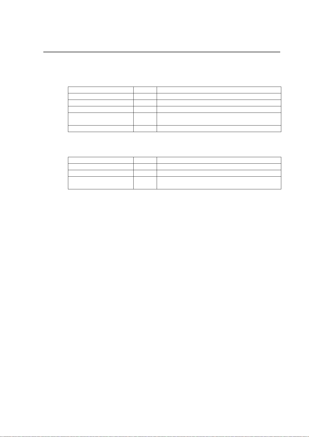
Open the VFC-1000 package and make sure the package contains the items shown in the
following parts list.
If you ordered the VFC-1000 only (no options):
ITEM QTY REMARKS
VFC-1000 camera 1 Standard 256MB internal memory
AC-DC adaptor 1 For 16V DC VFC-1000 only
AC cord 1 For AC-DC adaptor
Image conversion
software CD-ROM
Operation manual 1 This document
The following options are listed on a label on the bottom of the camera. Check the label to
make sure you received any options you ordered.
ITEM QTY REMARKS
8 SEC 1 8-second recording time, 512MB memory option
16 SEC 1 16-second recording time, 1GB memory option
8 kF 1 Adds record speed selection range of 2000 to
If package or its contents have been damaged, contact the freight company immediately. If any
parts are missing, or if you received the wrong parts, contact your dealer.
1
For AVI and BMP format conversion of camera
images
8000 frames/second
Page 10

Page 11

Table of Contents
1. Introduction..............................................................................................................1
1-1. Introduction .......................................................................................................1
1-2. Overview...........................................................................................................1
1-3. Features............................................................................................................1
1-4. Operation Requirements...................................................................................2
1-4-1. Basic System .............................................................................................2
1-4-2. Requirements for PC..................................................................................2
2. Part Names and Functions......................................................................................4
2-1. Camera Rear Panel ..........................................................................................4
2-2. Connector Pin Assignments..............................................................................6
2-2-1. AUX Connector...........................................................................................6
2-2-2. REMOTE Connector ..................................................................................7
3. Setup and Connections ...........................................................................................8
3-1. Preparing Equipment for Connection................................................................ 8
3-1-1. PC for Controlling Camera .........................................................................8
3-1-2. Connector Cables.......................................................................................8
3-1-3. AC-DC Adaptor........................................................................................... 8
3-1-4. Lens ...........................................................................................................9
3-1-5. Tripod .........................................................................................................9
3-2. Cable Connections .........................................................................................10
3-2-1. One Computer to One VFC-1000.............................................................10
3-2-2. One Computer to Two VFC-1000s ...........................................................11
3-2-2. One Computer to Three or More VFC-1000s ...........................................12
3-2-3. VFC-1000 Remote Control Unit Connection ............................................13
4. Operation...............................................................................................................14
4-1. System Setup .................................................................................................14
4-1-1. Startup Screen.......................................................................................... 14
4-1-2. Setting PC’s IP Address ...........................................................................16
4-1-3. Internet Explorer Settings.........................................................................20
4-1-4. Camera Control Window ..........................................................................21
4-2. Controlling the Camera...................................................................................23
4-2-1. Camera Status Display Area.....................................................................23
4-2-2. Mode Settings Area..................................................................................24
Page 12

4-2-3. Record Settings Area............................................................................... 26
4-2-4. Image Quality Settings Area .................................................................... 30
4-2-5. Playback Settings Area............................................................................ 31
4-2-6. System Settings Area .............................................................................. 31
4-3. Record Operations ......................................................................................... 36
4-3-1. VIEW Mode.............................................................................................. 36
4-3-2. ARM Mode............................................................................................... 36
4-3-3. REC Mode ............................................................................................... 37
4-4. Playback Operations ...................................................................................... 38
4-4-1. Playback (Forward).................................................................................. 39
4-4-2. Playback (Reverse) ................................................................................. 39
4-4-3. LOOP playback........................................................................................ 39
4-4-4. Playback Range....................................................................................... 40
4-4-5. Playback Frame Advance/Back Buttons, Slide Bar.................................. 40
4-4-6. Saving Camera Images to PC ................................................................. 41
5. Converting Images to AVI Format ......................................................................... 43
5-1. Installing the VFCIC Camera Image Conversion Software............................. 44
5-2. Operations...................................................................................................... 47
5-2-1. Displaying cm8 Images............................................................................ 47
5-2-2. AVI Conversion ........................................................................................ 51
5-2-3. BMP Conversion...................................................................................... 53
5-2-4. Displaying AVI and BMP Images ............................................................. 54
5-3. Uninstalling VFCIC......................................................................................... 55
6. Record Tips........................................................................................................... 56
6-1. Recording Rate and Shutter Speed................................................................ 56
6-2. Lens Selection................................................................................................ 57
6-3. Lighting........................................................................................................... 58
7. Specifications and Dimensions ............................................................................. 59
7-1. System Specifications .................................................................................... 59
7-2. External Dimensions ...................................................................................... 62
Page 13

1. Introduction
1-1. Introduction
Congratulations! By purchasing VFC-1000 Variable Frame Rate Camera you have entered the
world of FOR-A and its many innovative products. Thank you for your patronage and we hope
you will turn to FOR-A products again and again to satisfy your video and audio needs.
To ensure proper use of this product, please carefully read this Operation Manual. After you
finish reading the Manual, keep it in a handy place for future reference.
1-2. Overview
The VFC-1000 Variable Frame Rate Camera is designed as a lightweight and miniaturized
stand alone high speed camera for easy operation and enables recording at up to 8000
frames/second.
Recorded images are stored in the internal memory, and replayed as slow-motion standard
television signal (NTSC or PAL). Also the digital images are downloaded to the PC to analyze
motion images.
1-3. Features
Recording rate: 250 frames/second at full frames (512 × 472 pixels); up to 8000
frames/second at 128 × 34 pixels for excellent price performance
High-speed electronic shutter: With a maximum operation speed of 1/100000 second, the
high-speed shutter enables recording of high-speed phenomena without blurring.
Small, lightweight, integrated design: Enables using wider applications, easy handling for
recording in field, laboratory, production line of a factory, easy recording in tough
environment
High image quality: Excellent image quality improves accuracy of analyzing high-speed
phenomena and processing of images.
Product lineup: Select a high-sensitivity/high-resolution monochrome model or color model
to suit your needs. Infrared capability is also available as optional feature.
Record time: Standard record time is 4 seconds, optionally increased to 16 seconds.
Multiple functions: Flexible record setup and a variety of playback modes.
Analog video output: Use live images to enable easy setting of the recording conditions;
and immediate playback of recorded images allows quick analysis and easy problem
solving.
Digital interface: Ethernet interface on the camera need not any special PC interface board
(such as a PCI card) to control camera and transfer image data.
Synchronized operation of multiple cameras: Master/slave controls two cameras, and
multi-camera synchronization distributor (optional) controls three or more.
1
Page 14

1-4. Operation Requirements
This section presents the requirements for controlling the VFC-1000.
1-4-1. Basic System
The following equipment is needed to control your VFC-1000 via PC.
VFC-1000 camera
AC-DC adaptor
Lens (C mount)
PC for controlling VFC-1000
Video monitor (NTSC/PAL)
Video cables
LAN cable
Trigger cable (when external trigger is used)
1-4-2. Requirements for PC
Following are the system requirements for the PC used to control the VFC-1000, download
recorded images, and convert them to AVI or BMP format.
Windows 2000 Professional SP2 OS or later
Pentium III 700MHz or better CPU
At least 128MB of memory
At least 1GB of free disk space (Disk space required varies according to the amount of
image files to be saved. Image data requires 262 KB per frame.)
Ethernet 100Base-TX network interface
Display monitor with a resolution of 800 × 600 or higher
Internet Explorer 6.0 (IE5.5 will work, but control window may not be
properly displayed.)
Internet Explorer should be set so that JavaScript will run on it.
Internet Explorer should be set to allow Cookies to run. (Cookies are
required to save camera settings.)
2
Page 15

Camera IP address and PC Internet settings should be properly made.
VFCIC camera image conversion software should be installed (to
playback recorded images downloaded to the PC and convert them to
AVI or BMP format).
It is not necessary to install the special software on your PC if you only use it to control the
VFC-1000 without converting images.
3
Page 16
2. Part Names and Functions
2-1. Camera Rear Panel
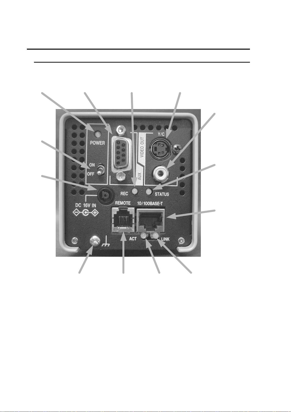
The names and functions of connectors, switches, and indicators on VFC-1000’s rear panel
are shown below.
①
②
③
⑫
⑪⑧
⑩
⑨
⑤
⑦⑥④⑬
Fig. 2-1
4
Page 17

① POWER indicator
Lights yellow to indicate camera power is on.
② POWER switch
Power switch of this camera.
③ 16V DC IN connector
Used for connection to AC power source via supplied AC-DC adaptor.
④ REMOTE connector
Optional remote control unit connects here to control the camera.
⑤ 10Base-T/100Base-TX connector
Used for connection to PC or HUB with a LAN cable (Cat. 5)
⑥ ACT indicator
Flashes orange slowly to indicate Ethernet transfers.
⑦ LINK indicator
Lights yellow to indicate Ethernet link is complete.
⑧ REC indicator
Lights orange to indicate the VIEW mode (live/set up for record).
Flashes red to indicate the ARM mode (waiting for the trigger signal).
Lights red to indicate the REC mode (on recording).
Flashes green to indicate PLAY and LOOP mode (on playing back )
Lights green to indicate the STOP mode (playback still images).
⑨ STATUS indicator
Lights orange to indicate while a video signal is being output.
⑩ VIDEO OUT connector (NTSC/PAL)
Connector used to output NTSC or PAL video signal.
⑪ VIDEO OUT connector (S)
Connector used to output NTSC or PAL S-video signal.
⑫ AUX connector
Connector used for I/O connection of synchronous signals or trigger signals.
⑬ FG terminal
Frame ground terminal.
When the VFC-1000 is being used, be sure this terminal is connected to a ground which is
fixed to the facility.
5
Page 18
2-2. Connector Pin Assignments
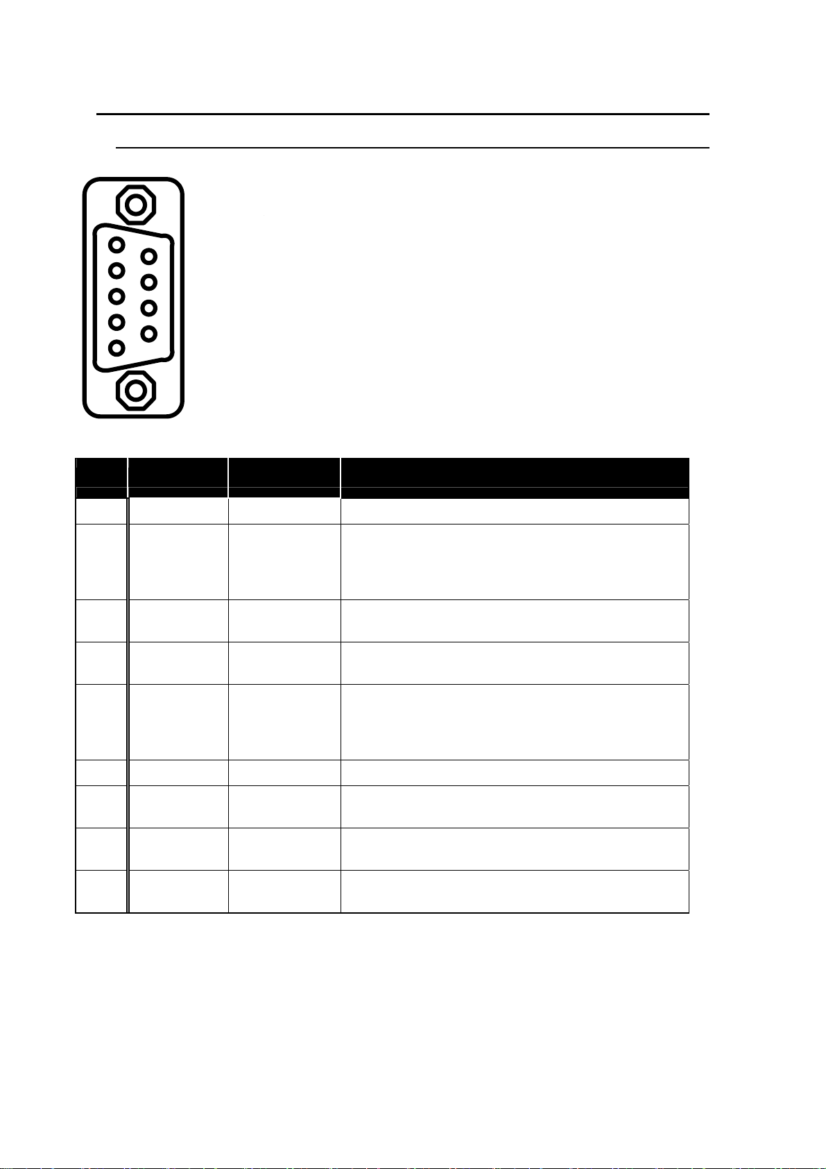
2-2-1. AUX Connector
Part name: Japan Aviation Electronics Industry, Ltd. DELC-J9SAF-20L6
型名:日本航空電子工業㈱DELC-J9SAF-20L6
Cable connector security screws: #4-40 (inch screw)
嵌合固定用ネジ:#4-40(インチネジ)
1
2
3
4
5
6
7
8
9
GND
1. SG
2. FPLUSE
FPULSE
3. N.C.
4. N.C.
5. TRIG
GND
6. SG
7. AUX4
AUX
8. N.C.
9. N.C.
AUX Connector Pin Assignments and Signals:
Pin No. Use Signal Description
1 GND — — Signal ground
a) Frame pulse output
2 FPULSE
(Usage not
3
allowed)
LVTTL output
(negative logic)
— —
Used as a sync signal during synchronized
recording or as a strobe trigger signal.
Not used (do not connect)
(Usage not
4
allowed)
5 TRIG
6 GND — — Signal ground
7 AUX
(Usage not
8
allowed)
(Usage not
9
allowed)
— —
LVTTL input
(negative logic)
LVTTL input
(negative logic)
— —
— —
Not used (do not connect)
b) External input
10kΩ pull-up process is performed internally.
When connecting a switch, contact resistance
of switch and cable must be 1kΩ or less.
c) Camera sync signal input
Used to input master camera frame pulse.
Not used (do not connect)
Not used (do not connect)
6
Page 19
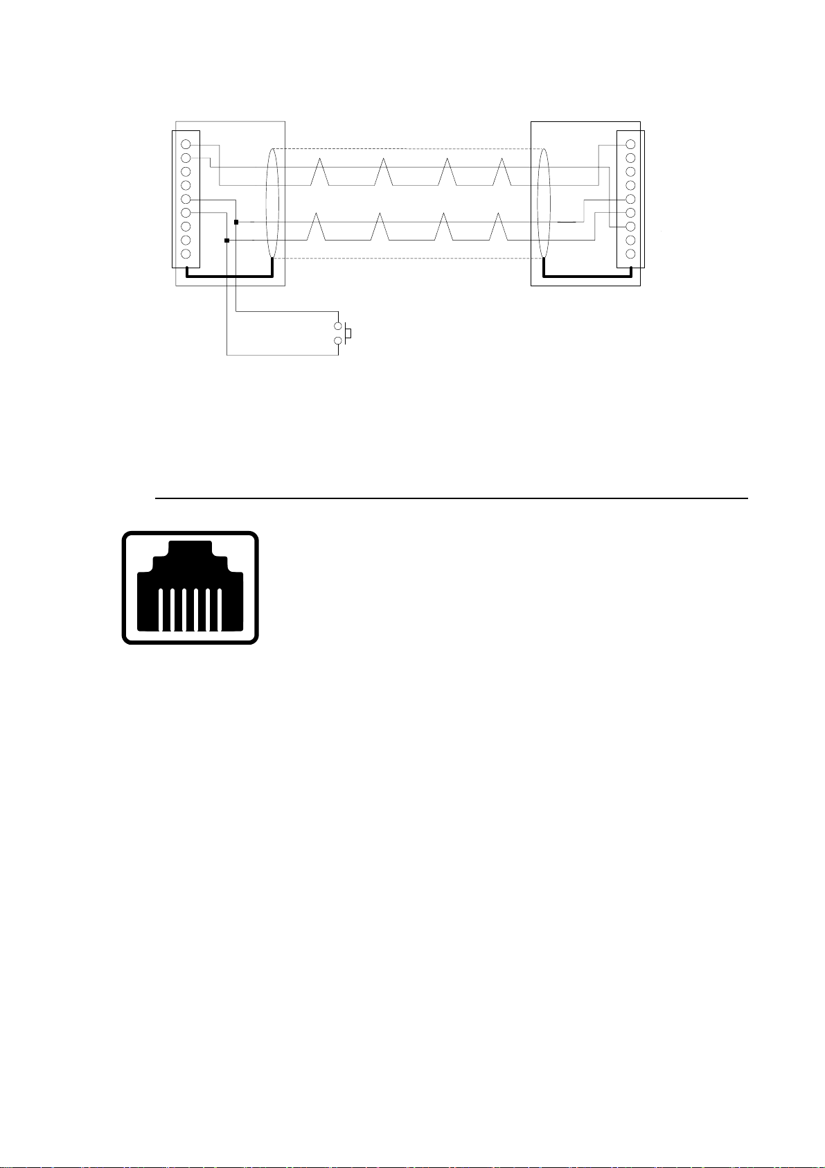
(
)
Fig. 2-2-1 An example of camera synchronization cable connections.
GND
1. SG
GND
2. FPLUSE
FPULSE
3. N.C.
4. N.C.
5. TRIG
6. SG
GND
AUX
7. AUX4
8. N.C.
9. N.C.
Trigger switch
トリガスイッチ
1. SG
2. FPLUSE
FPULSE
3. N.C.
4. N.C.
5. TRIG
6. SG
GND
AUX
7. AUX4
8. N.C.
9. N.C.
Master camera AUX connector Slave camera AUX connector
Fig. 2-2-1
For information on making camera sync cables and trigger cables, contact us or your dealer.
2-2-2. REMOTE Connector
Part number: Hosiden Corporation
TM11R-5C-66
型名:ホシデン(株) TM11R-5C-66 (RJ-11相当品)
RJ-11 equivalent
1. FG
2. TD
3. RD
4. UNREG
5. UNREG
23456
1
6. SG
GND
7
Page 20

3. Setup and Connections
3-1. Preparing Equipment for Connection
3-1-1. PC for Controlling Camera
Make ready a PC satisfying the requirements in Sec. 1-4-2. for use in controlling the
camera.
3-1-2. Connector Cables
LAN cable: Use Cat 5 (100Base-TX) cross wired cable to directly connect camera to
PC. Use a straight wired cable to connect camera and PC via hub.
AUX cable: Connects to AUX connector and used to input/output external trigger
signals and multi-camera sync signals (also used for strobe wiring sync
signals). Contact your dealer for information on cable specifications.
Video cables
VIDEO OUT jack: Use a 75Ω coaxial cable with RCA pin jack.
S jack: Connect an S cable with S connector.
3-1-3. AC-DC Adaptor
Connect the AC-DC adaptor included with the VFC-1000.
The polarity of the supplied AC-DC adaptor may be different from other AC-DC
adaptors. Only use the AC-DC adaptor included with the VFC-1000.
8
Page 21

3-1-4. Lens
The VFC-1000 uses the most popular C mount lens. When high speed camera records
high speed events, more illumination is required as the frame rate increases. Therefore,
provide large aperature lenses (or small iris Range, F No).
In particular, for recording high-quality images we recommend a 2/3-inch or 1/2-inch
high-performance industrial lens (or megapixel CCD lens) which has high resolution, low
distortion, and improved shading, anti shock and vibration rocking screw.
The higher the recording rate on the VFC-1000, the narrower the field of view. For details,
see Sec. 6-2. “Lens Selection”.
CS mount lens cannot be used.
Nikon F mount lens can be used with F-C adaptor.
3-1-5. Tripod
The VFC-1000 camera has 1/4-inch and 3/8-inch type mounting screw holes for a tripod.
Use a tripod with mounting screws in either of these sizes.
The larger the tripod size, the more stable the camera will be, thus enabling record to occur
without blurring.
9
Page 22
A
3-2. Cable Connections
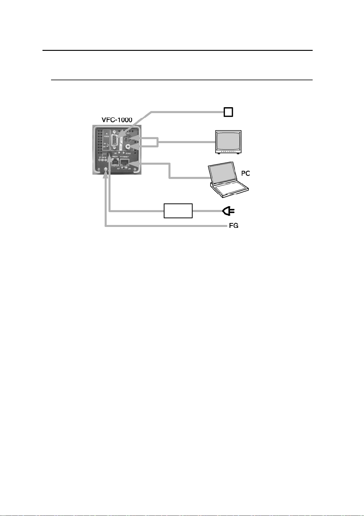
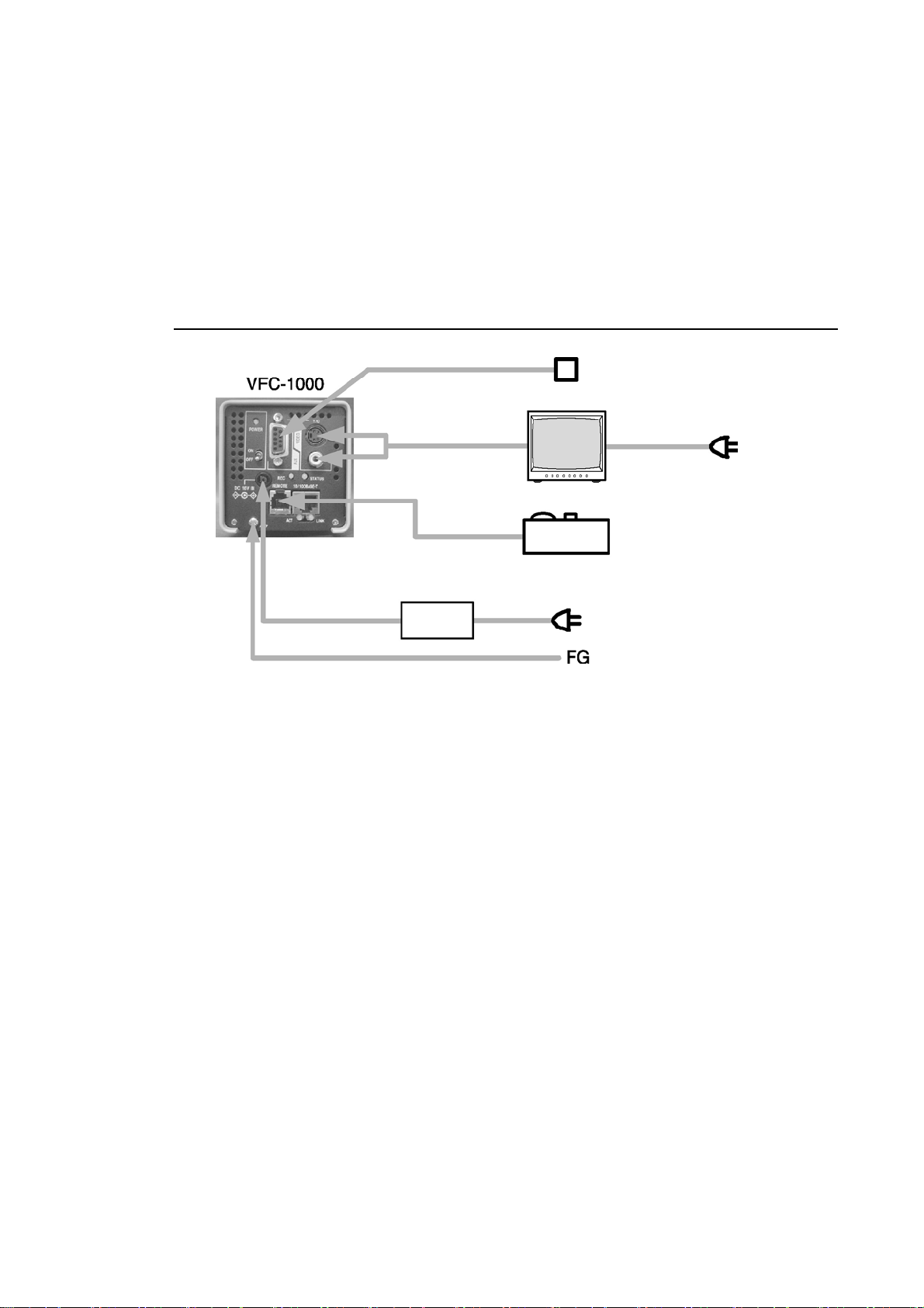
Typical examples of connection between VFC-1000s and PCs are shown below.
3-2-1. One Computer to One VFC-1000
Power cable
FG cable
Trigger cable
Video cables
LAN cable
C-DC adaptor
Fig. 3-1
Trigger switch
Video monitor
Use a cross wired type LAN cable.
For video cables, use 75Ω coaxial cable with an RCA pin jack at VIDEO OUT jack, and
use S cable at S output jack. Video can be output via both connectors simultaneously.
Type of AUX cable used varies depending on the camera application and the system
configuration. In the example shown in Fig. 3-1, AUX cable supplies trigger signal only.
Be sure to connect FG terminal to ensure stable operation.
10
Page 23
r
A
A
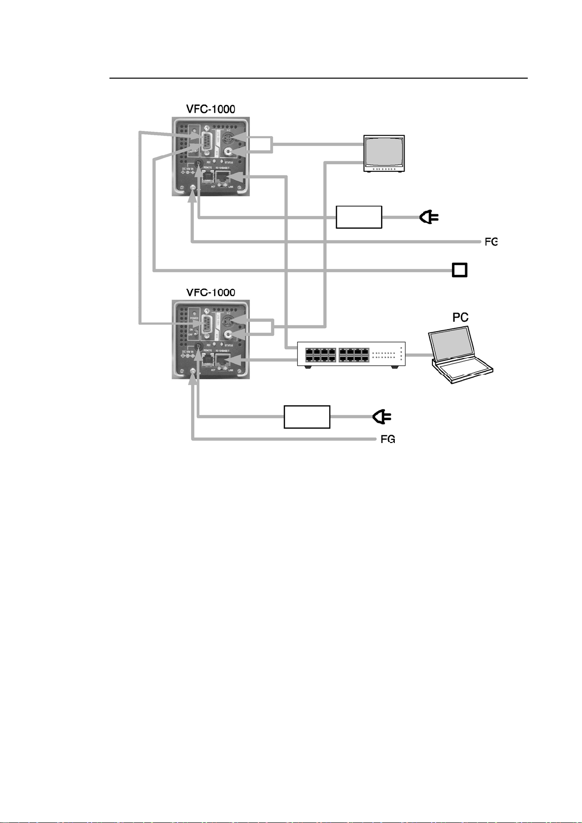
3-2-2. One Computer to Two VFC-1000s
Camera
sync cable
Camera
sync cable
cable
Powe
FG cable
Power cable
FG cable
Video cables
LAN cable
LAN cable
C-DC adaptor
Fig. 3-2
Video monitor
C-DC adaptor
Trigger cable
Video cables
Hub
Trigger switch
Connect LAN cables to PC via hub. In this configuration, use straight wired type LAN
cables.
Video output is the same as in a single-camera configuration. Video signals from two
cameras can be displayed on a two-channel input monitor using the monitor’s internal
input switch. On a single-channel input monitor, external switching is required.
Cable for sync signal/simultaneous trigger signal supplied from master camera to slave
camera connects to the AUX connector.
Be sure to connect FG terminal to ensure stable operation.
11
Page 24
r
A
A
A
A
A
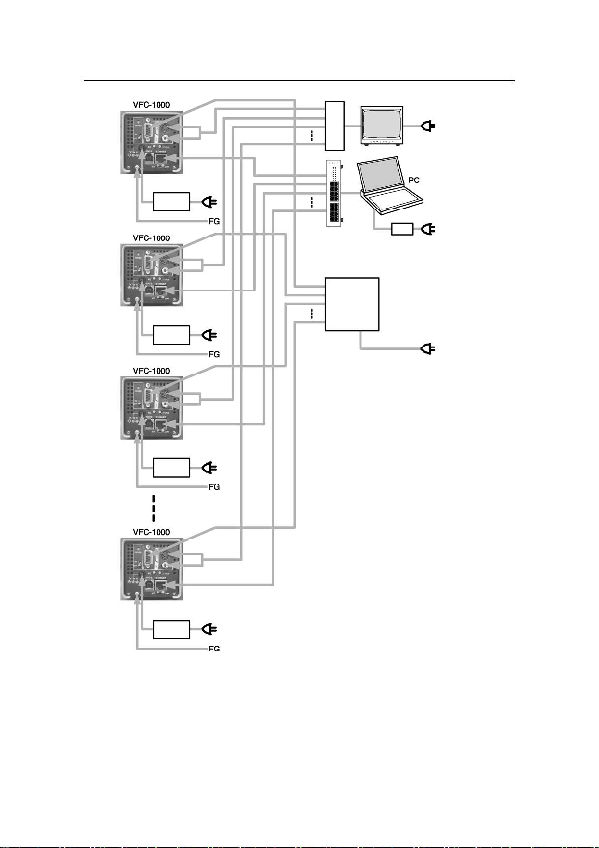
3-2-2. One Computer to Three or More VFC-1000s
C-DC adaptor
C-DC adaptor
Video switche
Video monitor
Hub
C-DC adaptor
Multi-camera
sync distributor
(option)
C-DC adaptor
C-DC adaptor
Fig. 3-3
12
Page 25
A
Connect LAN cables to PC via hub. In this configuration, use straight wired type LAN
cables. Video signals from multiple cameras are input to monitor via video switcher
(optional), or by manually changing cable connecting to monitor.
During synchronized operation of three or more cameras, a synchronous signal is
supplied to each camera from a multi-camera sync distributor (optional). The distributor
is equipped with a trigger switch which triggers all of the cameras at the same time.
Be sure to connect FG terminal to ensure stable operation.
3-2-3. VFC-1000 Remote Control Unit Connection
C-DC adaptor
For applications that do not require record images to be downloaded to PC, a remote
control unit (option) can be used instead of the PC to control the camera. The remote
control unit connects to the REMOTE connector.
Trigger switch
Video monitor
Remote control unit
(option)
Fig. 3-4
For information on controlling multiple cameras via remote control unit, contact your
dealer or nearest For-A’s office.
It is not possible to use a remote control unit and a LAN connected PC at the same time.
13
Page 26
4. Operation
The VFC-1000 camera contains all the software and data needed for camera control. Internet
Explorer, which is supplied with Windows, is used to control the camera, so there is no need to
install special software applications.
4-1. System Setup
4-1-1. St artup Screen
Connect equipment as described in 3-2. “Cable Connections”.
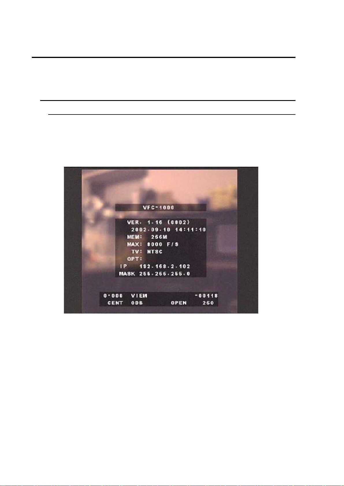
Turn on the camera and monitor. After about 30 seconds, the camera’s live screen will
be displayed with camera version and other information (Fig. 4-1-1). (Noise will appear
on the monitor during camera initialization. This is not a failure of the equipment.)
Fig. 4-1-1
14
Page 27

The following information is displayed on the startup screen.
VER. 1.16 (0002) Internal software version (product serial number)
2002.09.10 14: 11: 10 Version date of internal software
MEM: 256MB Internal memory size (varies depending on model/options added)
MAX: 8000 F/S Maximum recording rate (varies depending on model/options added)
TV: NTSC Output TV system (NTSC/PAL)
OPT: Option specifications are displayed. (Normally blank.)
IP 192.168.2.102 Camera IP address
MASK 255.255.255.0 Camera subnet mask
0-000 Camera scene No.
VIEW Camera mode
–00118 Frame number that is currently displayed.
CENT Trigger mode
ODB Camera gain
OPEN Shutter speed
250 Recording speed (frame rate)
For information on the details displayed, refer to the explanation in the
corresponding section.
15
Page 28
4-1-2. Setting PC’s IP Address
Set the network IP address of the PC for controlling the camera to adapt to the network
settings of the VFC-1000 being used. Set the PC’s network as the following procedure.
In camera startup screen, check camera’s IP address and subnet mask. (In Fig. 4-1-1,
IP address is 192.168.2.102 and subnet mask is 255.255.255.0).
The factory default IP address for all VFC-1000s has been set to 192.168.2.1xx (xx
denotes the last two digits in the product serial number), and the subnet mask to
255.255.255.0.
Setting PC’s IP address
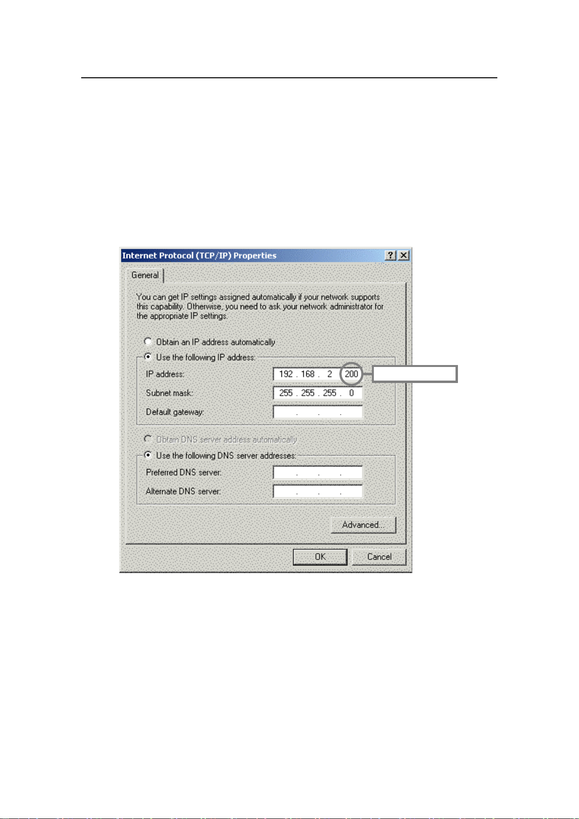
‘Start’ menu ‘Settings’ ‘Network and Dial-up Connection’ Double-click the ‘Local
Area Connection’ icon ‘Properties’ Double-click ‘Internet Protocol (TCP/IP)’.
Double-click, then enter the settings shown below.
* See below.
Fig. 4-1-2
After completing settings, click ‘OK’ and close all windows (Internet Protocol and Local
Area Connection Properties).
If VFC-1000 is in factory default settings, the PC’s IP address can be set to
192.168.2.yyy (yyy denotes a number from 1 to 254, excluding the camera’s
number/See * in Fig. 4-1-2), and the subnet mask to 255.255.255.0.
Checking IP address setting
A tool called Ping is used to make sure the IP address has been set properly.
16
Page 29

From the ‘Start’ menu, select ‘Programs’ ‘Accessories’ ‘Command prompt’ to
display the command prompt window.
In the command window, type “ping 192.168.2.1xx” (xx denotes the IP address of the
camera being connected), then press Enter key.
If the reply shows four lines as below, then setting is normal.
“Reply from 192.168.2.1xx: bytes=32 time=10ms TTL=255”
If a reply message appears as below, then the setting is not properly completed.
“Request timeout.”
“Reply from 192.168.2.1xx: Destination host unreachable.”
In such cases, see “◇ When an error occurs while connecting to the network”.
17
Page 30

When an error occurs while connecting to the network
A) If “Request timeout.” is displayed
Check the following to make sure network cables and hub (if used) are properly connected.
The camera’s LINK indicator should be on.
When the ping command is entered, the camera’s ACT indicator should flash.
The LINK indicators on the PC and hub should be on. (Some PCs and hubs may not
have a LINK indicator.)
When ping command is entered, ACT indicators on the PC and hub should flash. (Some
PCs and hubs may not have an ACT indicator.)
If the above conditions are satisfied, then there are no problems with the cable connections
or related situations. If the above conditions are not satisfied, then there may be a problem
with the connected cables, the hub, or with the network settings.
18
Page 31

B) If there are no problems with the connected cables or network devices, and the following
message appears after pinging
Reply from 192.168.2.1xx: Destination host unreachable.
Type “ipconfig /all” in the command prompt window (the window where the Ping
command was entered), then press Enter key.
Check the underlined areas shown below.
Ethernet adaptor: (Varies depending on type of PC used.)
Description: (Varies depending on type of PC used.)
Physical Address: (Varies depending on type of PC used.)
DHCP Enabled: No
IP Address: 192.168.2.yyy
Subnet Mask: 255.255.255.0
Default Gateway: . . . . .
DHCP Server: . . . . .
Primary WINS Server: . . . . .
(This should be the IP address set for PC.)
(This should be the subnet mask set for PC.)
(This should be blank.)
(This should be blank.)
(This should be blank.)
Lease Obtained:
Lease Expires:
If the information on the screen does not appear as shown above, go back to the procedure
shown under 4-1-2. “Setting PC’s IP address” and reenter the settings.
If there are no problems with the above settings, then there is a problem with the
network environment. Contact your PC or network administrator.
19
Page 32

4-1-3. Internet Explorer Settings
Confirm that Internet Explorer is set up to run JavaScript and Cookies.
Open Internet Explorer, then select ‘Internet Options’ from the ‘Tools’ menu. Click the
‘Security’ tab, then click the ‘Local intranet’ Web content zone. If this zone has been
customized (if ‘Default Level’ button displayed), click the ‘Default Level’ button. Internet
Explorer will now be able to use JavaScript and Cookies will be enabled.
About Cookies
When using the VFC-1000, a JavaScript program is downloaded from the camera to the
PC since the browser runs part of the control program. In addition, the VFC-1000 stores set
record parameters, so this information is converted to data known as Cookies for use by
the browser, and these Cookies are stored on the PC.
Next, check active language on the same menu.
Click the ‘General’ tab, then click the ‘Languages’ button and make sure that ‘English (en)’
is displayed in the ‘Language’ field. If it is not displayed there, then the VFC-1000 control
screen messages will appear in English.
20
Page 33
4-1-4. Camera Control Window
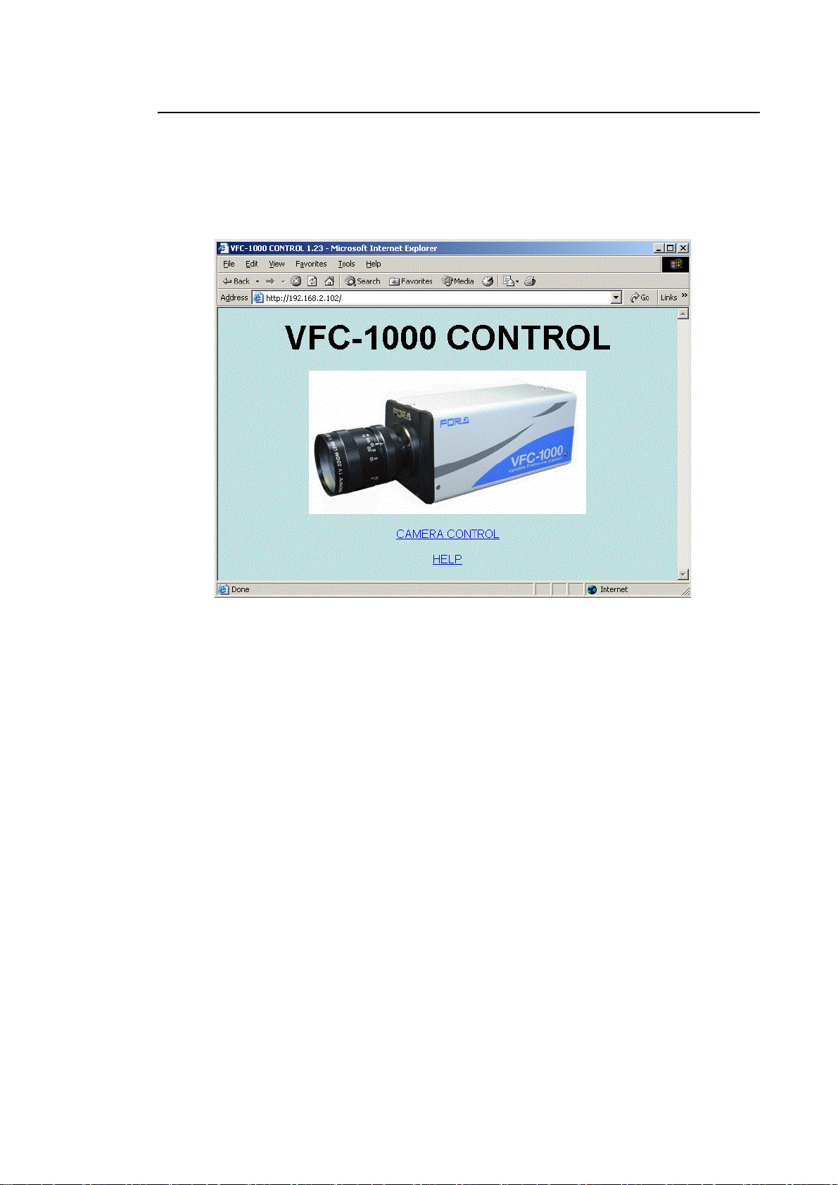
Open Internet Explorer, and enter the camera’s IP address in the ‘Address’ field. The IP
address to be entered is shown on the video monitor when the camera is started up. (In
case of Sec. 4-1-1. “Startup Screen”, enter "192.168.2.102".)
When the PC is successfully connected with the camera, the CAMERA CONTROL
window (Fig. 4-1-4) will be displayed.
Fig. 4-1-4
If camera and PC cannot connect to each other
Check whether PC’s settings for proxy server is OFF as the following procedure:
Open Internet Explorer Go to ‘Tools’ ‘Internet options’ ‘Connections’ ‘LAN
settings’ Uncheck ‘Use a proxy server for your LAN’ Click ‘OK’.
If the PC and camera still cannot connect to each other, contact your PC or network
administrator.
21
Page 34
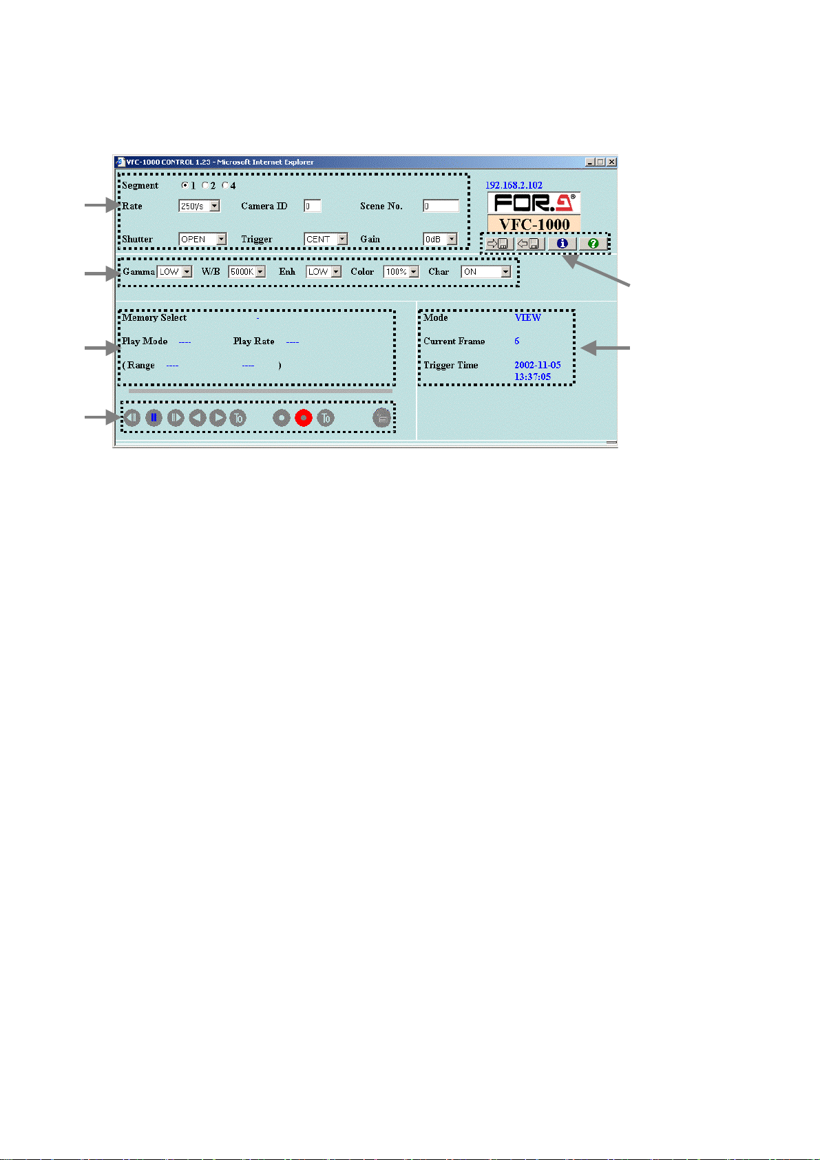
When you click the CAMERA CONTROL line in the CONTROL window, another camera control
window (Fig. 4-1-5) opens at the PC, and the camera startup screen on the video monitor
disappears.
③
④
⑥
① ⑤
②
Fig. 4-1-5
The control window is divided into the following functions:
① Camera status display area
② Mode settings area
③ Recording settings area
④ Image quality settings area
⑤ Playback settings area
⑥ System settings area
22
Page 35
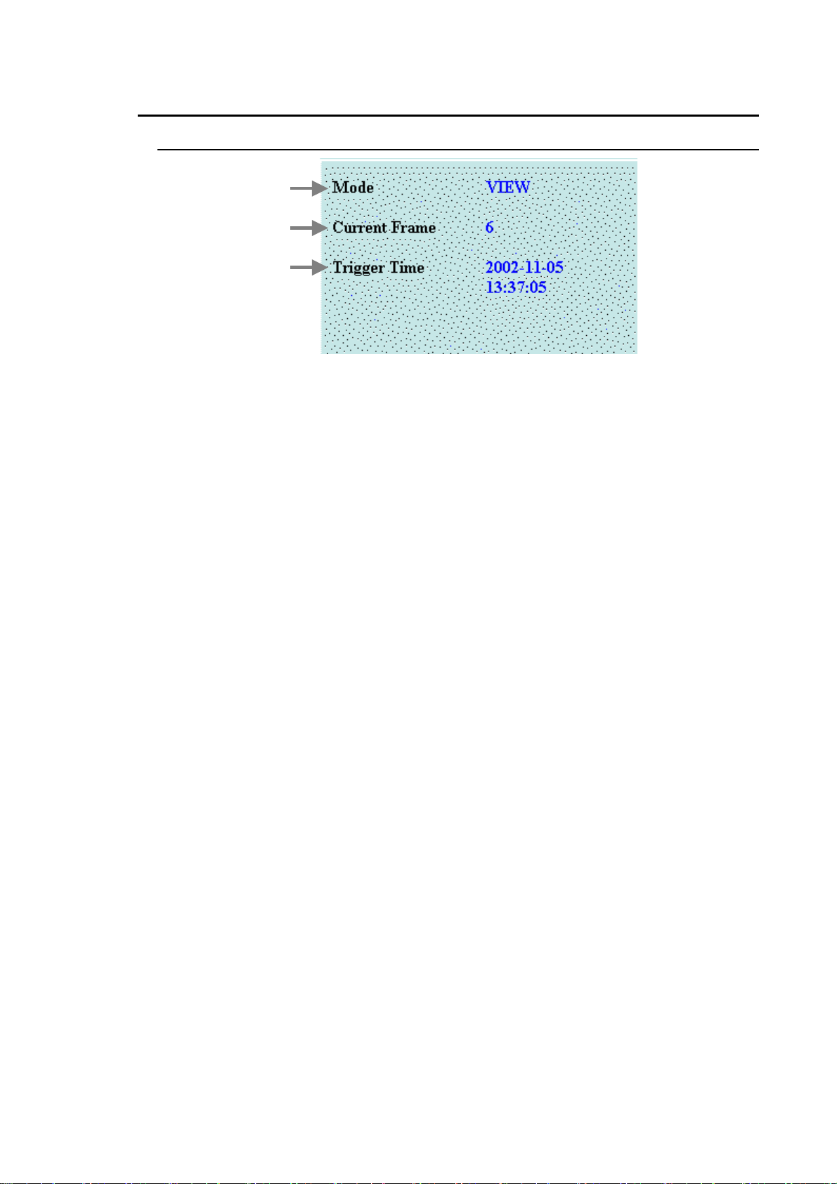
4-2. Controlling the Camera
4-2-1. Camera St atus Display Area
①
②
③
Fig. 4-2-1
① Mode: The camera has the following modes:
BUSY: In this mode, camera is internally processing control.
VIEW: In this mode, live image is displayed on the video monitor. Lens settings,
illumination conditions, recording parameters, and other settings are made
in this mode. The various record settings are done in VIEW mode.
ARM: In this mode, record standby status is displayed, and record is started by a
trigger signal.
REC: In this mode, a trigger signal has been input and record is in progress.
STOP: In this mode, record has ended and a still image is displayed. Various
record playback related settings are entered in STOP mode.
PLAY: In this mode, moving images are played at set playback speed.
LOOP: In this mode, moving images are played back repeatedly at set playback
speed over set playback frame range.
SAVE: In this mode, the playback frame images in the set range are being saved
to the PC.
② Current Frame: During playback (STOP, PLAY, and LOOP modes), the frame number
shown on the video monitor is displayed. The frame numbers are
counted up, with the trigger frame set to “0”. During record (VIEW,
ARM, and REC modes), the camera’s internal memory frame number
is displayed.
③ Trigger Time: Displayed during playback. The camera’s internal time at which the
trigger signal was detected in ARM mode is displayed in the format
“Year-Month-Day Hours: Minutes: Seconds”. The camera’s internal
time can be set. (See 4-2-6. System Settings Area)
23
Page 36
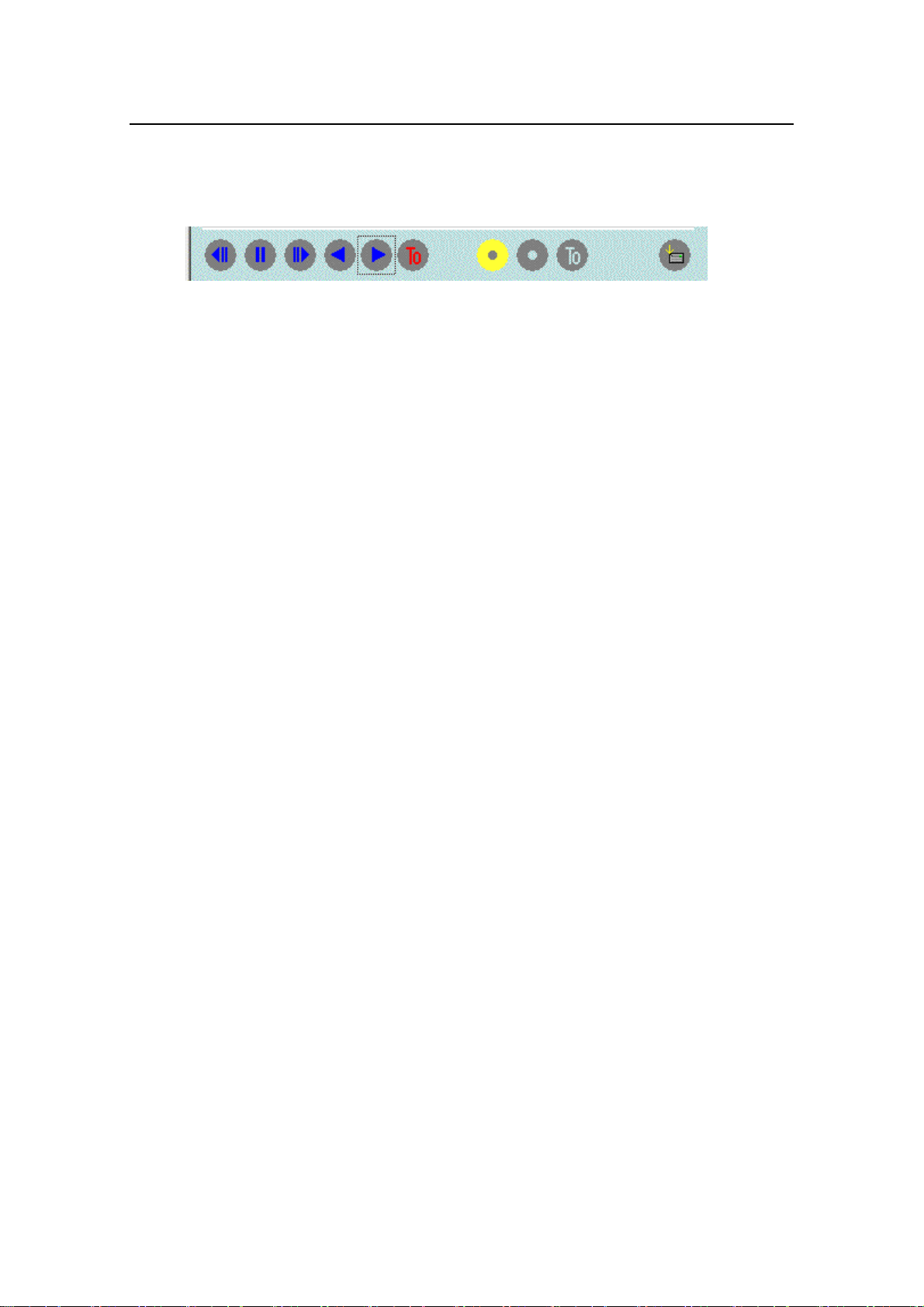
4-2-2. Mode Settings Area
This area is used to change camera mode and to control the moving of playback frames
with the buttons shown below. Buttons can be controlled as set camera mode. Some
buttons may be disabled depending on the camera mode. Disabled buttons appear in gray
on the screen.
⑨ ⑤ ⑧ ⑦ ⑥ ④ ① ② ③ ⑩
Fig. 4-2-2
① VIEW button: This button is used to change to VIEW mode from STOP mode.
② ARM button: This button is used to change to ARM mode from VIEW mode.
0 button (trigger): This button is used to enter a manual trigger in ARM mode.
③ T
Because communication takes place via LAN, there is a slight delay before the
trigger reaches the camera. Use an external trigger switch with which there will be
no delay, in order to precisely apply trigger at needed point.
0 button (frame number 0): This button is used to jump to a trigger frame in STOP
④ T
mode (frame number 0).
⑤ STOP button: This button is used to stop VIEW mode (if there is no image in
memory, VIEW mode is automatically entered). This button also stops moving
image playback in PLAY and LOOP modes.
⑥ PLAY button [forward]: This button is used to change to forward PLAY playback
(single playback) or LOOP playback (repeated playback) depending on the set
playback mode.
⑦ PLAY button [reverse]: This button is used to change to reverse PLAY playback
(single playback) or LOOP playback (repeated playback) depending on the set
playback mode.
⑧ STEP feed button (forward): This button is used to feed forward one frame in STOP
mode.
⑨ STEP feed button (reverse): This button is used to feed backward one frame in
STOP mode.
⑩ SAVE button: This button is used to save a recorded image to the PC.
24
Page 37
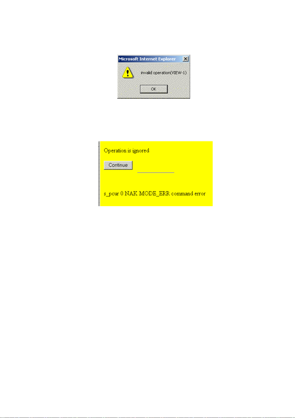
When a button is disabled in a particular mode
If you attempt an illegal action, such as clicking the VIEW button in PLAY or LOOP mode,
the message shown in Fig. 4-2-3 will appear. Click ‘OK’ to continue.
Fig. 4-2-3
In cases where you change the camera mode, and the settings become invalid (e.g., if you
attempt an action before the screen updates), the message shown in Fig. 4-2-4 will appear.
Click ‘OK’ to continue.
Fig. 4-2-4
25
Page 38
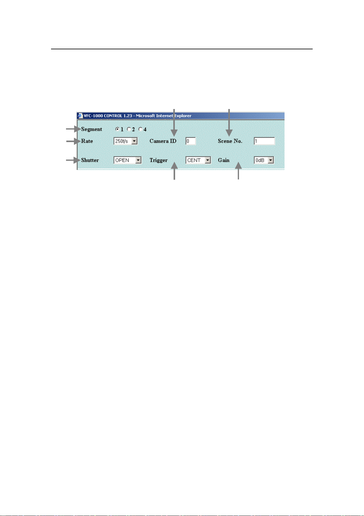
4-2-3. Record Settings Area
To record images, first set to VIEW mode. If the mode is not in VIEW mode, click the STOP
button to change to STOP mode, then click the VIEW button to set the VIEW mode. In
VIEW mode, you can set lens, illumination, and camera recording parameters while viewing
the live image on a video monitor.
Now you can enter settings in the Record Settings Area.
①
②
③
⑥
⑦
④
Fig. 4-2-5
① Segment setting: The camera internal memory is set as one full area or divided into
two or four segments, and images are recorded in each area (segment). Note that it
is not possible to set separate record parameters for each segment. In addition,
during segment record, it is not possible to play images or save them to PC until
recording is completed for all segments.
When you enter a memory segment setting, any image recorded in memory will be
lost. Therefore, if there is a recorded image in memory, first save the image before
entering the segment setting.
⑤
26
Page 39

② Recording rate setting: Click ▼ and select the useful recording rates from the
following indicated list:
50, 125, 250, 500, 1000, 2000, 4000, 8000f/s.
2000f/s and higher rates are optional.
At the higher recording rate the image size (number of effective pixels of the CCD) is
reduced, and the field of view is reduced, then the size of the playback images on
the video monitor also reduces.
Table 4-1-1 shows the recording rate and image size.
Table 4-1-1
Recording rate Image size
50, 125, 250 f/s 512 (h) × 472 (v) pix
500 f/s 512 (h) × 232 (v) pix
1000 f/s 256 (h) × 212 (v) pix
2000 f/s 256 (h) × 98 (v) pix
4000 f/s 128 (h) × 88 (v) pix
8000 f/s 128 (h) × 34 (v) pix
As the image size is reduced, an offset develops between the center of the recording
area of the CCD, and the lens optical axis. So, when the recording rate (image size)
is changed, you must adjust the camera position relative to the subject.
When you enter a memory segment setting, any image recorded in memory will be
lost. Therefore, if there is a recorded image in memory, first save the image before
entering the segment setting.
③ Shutter setting: Click ▼ and select the shutter speeds from the following values
corresponding to the motion speed of the subject.
OPEN, 1/250, 1/500, 1/2000, 1/5000, 1/10000, 1/20000, 1/50000, 1/100000 second
Shutter “OPEN” is available at recording rate of 250 f/s or more and exposure time is
1/rate.(e.g., if the recording rate is 250 f/s, then “OPEN” corresponds to 1/250
second).
Increasing the shutter speed eliminates blurring due to motion but more illumination is
required.
27
Page 40

r
④ Trigger mode setting: Three trigger modes can be selected: “START”, “CENTER”,
and “END”.
START: Recording starts when the trigger is input, and stops when memory is full.
Image data after trigger is recorded in the memory.
CENTER: Recording stops when the trigger is input. Image data of after trigger and
before trigger is recorded in the memory.
END: Recording stops when the trigger is input. Image data is recorded in the
memory.
Fig. 4-2-6 is an illustration of the trigger point of the three modes at 256MB memory, 1000 frames
The actual memory size is 5 percent in front of the memory start position for the START trigger,
and 5 percent back of the memory end position for the END trigger.
Start trigger
Frame 0
▼
0 1 2 3 ----- ----- ----- ----- ----- 997 998 999
Center trigger
▼
–449 –448 ---- ----- –2 –1 0 1 2 ---- 448 449
–999 –998 –997 ----- ----- ----- ----- ----- –3 –2 –1 0
Record stop
▽
Frame 999
Record stop
▽
End trigge
▼
Record stop
△
Fig. 4-2-6
28
Page 41

⑤ Gain setting: If the subject is not sufficiently illuminated and is not achieved enough
with the lens aperture, click ▼ and set the camera gain before recording.
–4dB: Set up when the sufficient illumination is received and high image quality is
especially required. This setting is equivalent to setting the lens IRIS to
approximately half-open.
0dB: This is the standard setting.
+6dB: Setting up when the illumination is not enough as the lens aperture is open.
This setting is equivalent to opening the lens aperture one step.
+12dB: This setting is equivalent to opening the lens aperture two step. With this
setting, noise in the images increases.
+18dB: This setting is equivalent to opening the lens aperture three step. Select this
setting when you want to give priority to brightness over noise.
⑥ Camera ID: In VIEW mode, a camera ID can be set 0 through 9. The initial setting
when the camera starts is “0”.
In multiple camera system, set camera ID to specify individual camera for
identification.
Camera ID is displayed on video monitor and included in saved image files in PC.
⑦ Scene No.: The Scene No. is a repeated number from 0 to 999. The initial setting is
“0” when the camera starts. Scene number automatically advances at each
recording. The Scene No. can be changed in VIEW mode.
29
Page 42
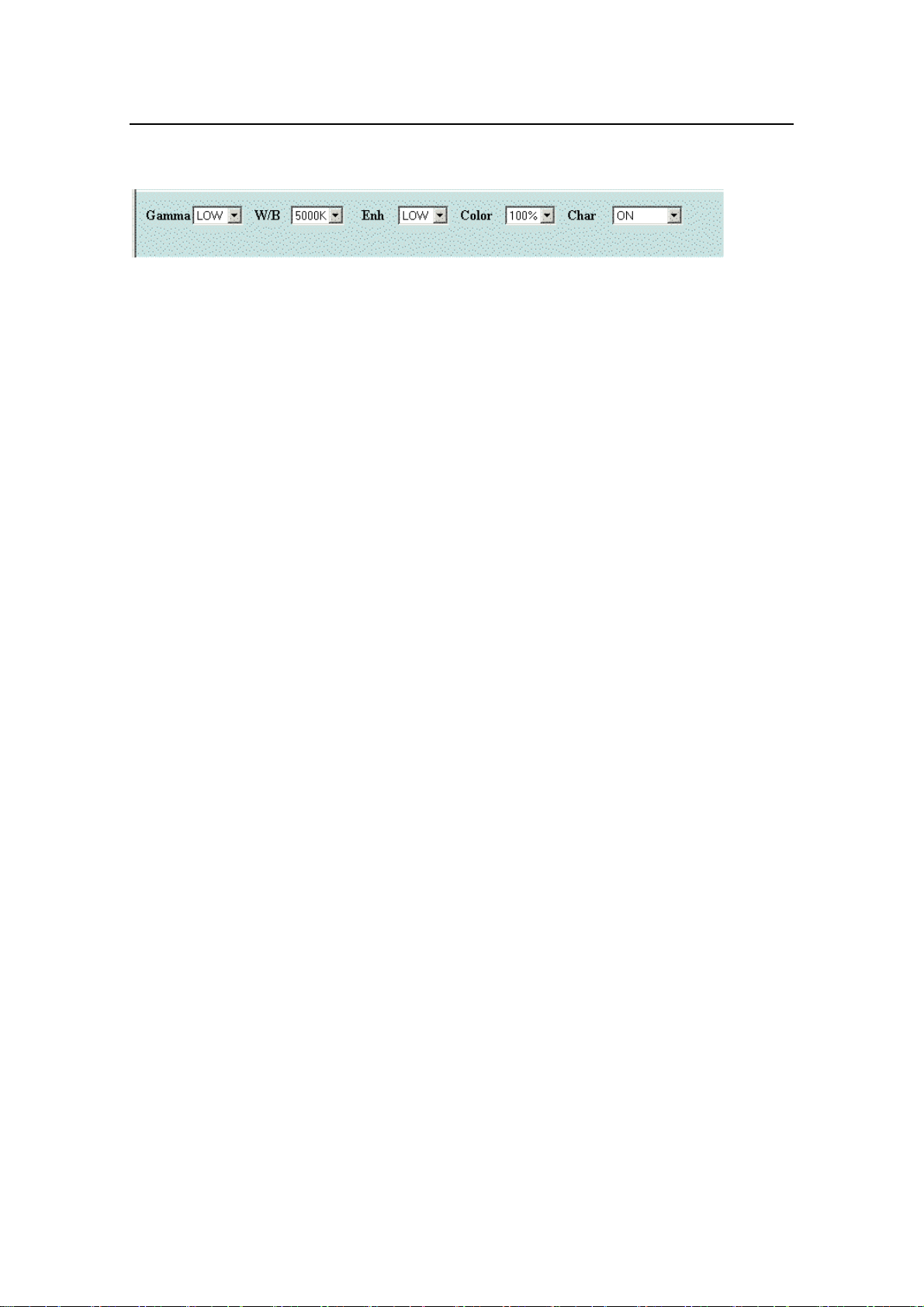
① ② ③④⑤
4-2-4. Image Quality Settings Area
Before recording, set up the camera to record the subject at the optimum image quality.
These settings are available for playback mode.
Fig. 4-2-7
① Gamma (gamma correction) setting: Set the dark area of the subject to improve.
OFF: Set to record the subject whose image is proportion to incident light for
image processing.
LOW: This is the normal setting. With this setting, dark areas of the subject
are corrected a moderate amount.
HIGH: Setting to correct the dark areas of the subject. This setting also
increases noise according to the amount of correction.
② W/B (white balance) setting: Set the white balance to correct the white parts of the
subject displayed to natural white.
3000K: Setting for recording with tungsten or halogen lighting.
5000K: Setting for recording with fluorescent lights, metal halide lights, or
strobe lighting.
9000K: Setting for recording outdoors on sunny or cloudy days.
③ Enh (enhanced) setting: Set an image’s outlines to enhance to sharp outlines.
OFF: Outline enhancement is not used with this setting.
LOW: Reduces outline blurring. This is the normal setting.
MID: Enhances the image’s outlines.
HIGH: Strongly enhances the image’s outlines.
Noise may become noticeable depending on the degree of
enhancement.
④ Color (color) setting: Set the color saturation in the subject. Normally set to 100%
(full color). For some application to image processing on the recorded images, you
can use the 0% setting (monochrome) according to your needs.
⑤ Char (character) setting: specifies whether or not the characters are displayed on
the monitor.
ON: The characters are displayed.
OFF: The characters are not displayed.
FCOUNT: Only the frame counter is displayed.
30
Page 43
r
4-2-5. Playback Settings Area
This area is used to select memory segments, and to set the playback mode, playback rate,
and playback range. See Sec. 4-4. “Playback” for information on the setting procedures.
4-2-6. System Settings Area
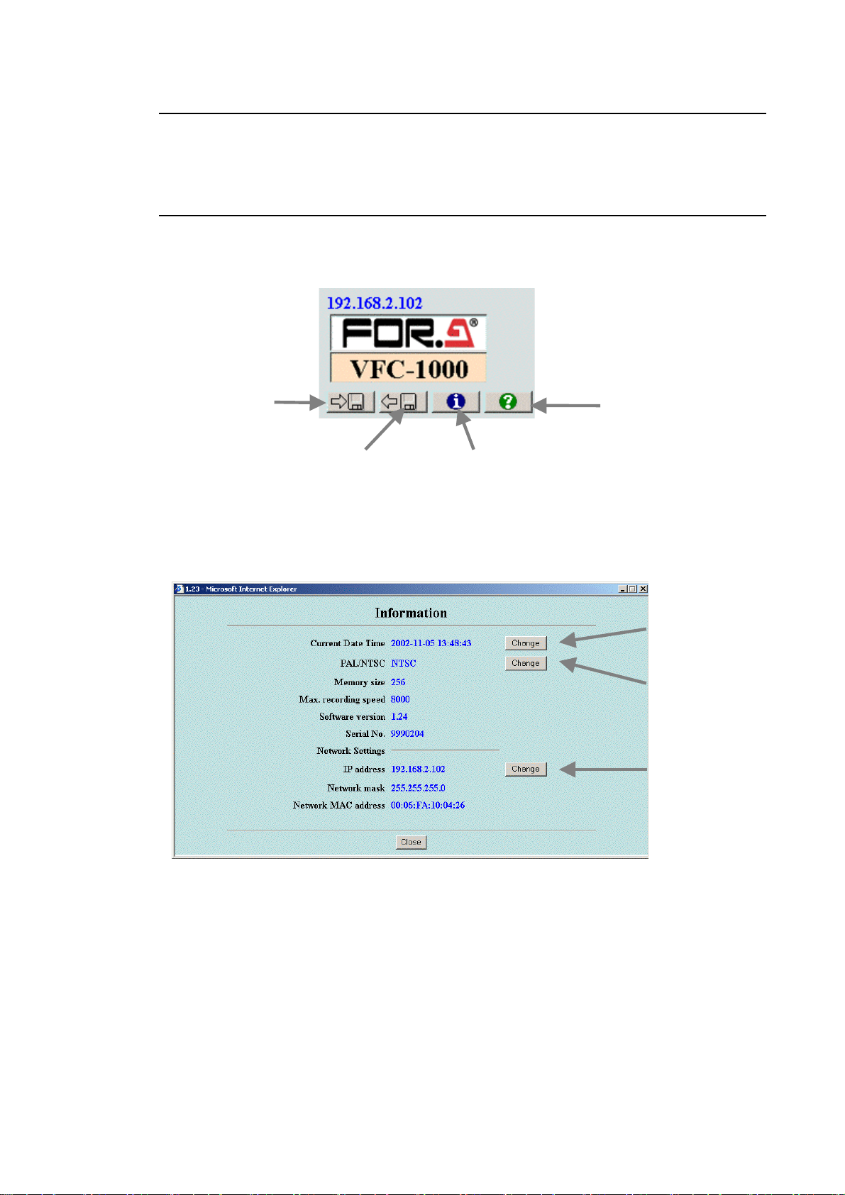
The camera information shown below can be displayed when the camera is in VIEW or
STOP mode (Information Window, Fig. 4-2-9). Camera settings can be saved to and loaded
from the PC. (See page 35, 36.)
Save paramete
button
Load parameter button
Information button
Fig. 4-2-8
Help button
② Date setting
button
① PAL /NTSC
setting button
③ IP address
setting button
Fig. 4-2-9
31
Page 44

① Camera date setting
When the camera is in VIEW mode or in STOP mode, camera time and date can be set.
Camera time and date are recorded together with images as trigger input time data during
recording. They are included in the information in the image files saved to PC. (Time and
date are not displayed on video monitor.)
Click information button in VIEW mode or in STOP mode to set the camera time and
date.
Click the Current Date time “Change” button on displayed information screen.
Enter date. The entry format is “Year (four digits)” – “Month” – “Day” – “Hour (24-hour
clock)”:“Minutes”. After entering time and date, you can display the information again to
check the time and date.
IMPORTANT
Camera clock is operated by an internal lithium battery having an approx. life span
of approx. 15 years (at 25° C). Battery will have to be replaced when the clock error
appears on your VFC-1000. Consult your FOR-A supplier regarding purchase of a
replacement battery.
② PAL /NTSC setting
The camera’s PAL /NTSC setting can be changed when the camera is in VIEW mode or in
STOP mode. The NTSC setting is factory default. It is necessary to change this setting if
you are connecting the camera to a video monitor conforming to PAL system format, and
when switching back to an NTSC monitor.
Click information display button in VIEW mode to change camera’s PAL /NTSC setting.
Click PAL/NTSC “Change” button on displayed information screen.
Click “Proceed” button.
Wait until “Setting of data to the camera are succeeded.” message appears.
Turn off the camera.
The new setting will take effect the next time the camera is started.
IMPORTANT
Never turn off the camera while the “Writing information to camera” message is on
the PC screen. Doing so will destroy data in the camera’s internal flash memory,
and the camera will need to be repaired.
32
Page 45

③ Changing camera’s IP address
You can change the camera’s IP address when camera is in VIEW mode or in STOP mode.
Before changing the camera’s IP address, you need to have finished connecting
the camera to PC using the default IP address.
Click information display button in VIEW mode or in STOP mode.
Click IP address “Change” button on displayed information screen.
Set IP address and corresponding subnet mask.
Click “Proceed” button.
Wait until the “Setting of data to the camera are succeeded” message appears.
Turn off the camera. The new setting will take effect the next time the camera is started.
Contact your network administrator for required IP address and subnet mask
settings. If you set the wrong IP address or subnet mask, the camera will no
longer be able to communicate with the PC, and it will not be possible to change
the settings. Restoration in such cases requires repair work (restoring to factory
default settings).
IMPORTANT
Never turn off the camera while the “Setting of data to the camera are succeeded”
message is on the PC screen. Doing so will destroy data in the camera’s internal
flash memory, and the camera will need to be repaired.
33
Page 46

④ Saving settings to PC
You can save camera settings to PC when camera is in VIEW mode or in STOP mode.
Saved data is saved separately from the camera’s network IP address. The Internet
Explorer’s Cookies function is used to save settings to PC. (For information on Cookies,
see “◆ About Cookies” in Sec. 4-1-3. “Internet Explorer Settings”.)
The settings shown below are saved.
Record area parameters
Segment (number of segments)
Rate (recording rate)
Shutter (shutter speed)
Trigger (START/CENTER/END)
Gain (record gain)
Camera ID (camera ID)
Scene No. (scene number)
Image quality adjustment parameters
Gamma (gamma)
W/B (white balance)
Enh (enhanced)
Color (color)
Char (video screen character display)
Procedure to save these settings is shown below.
Click the save parameter button.
A dialog box is displayed with the following message: “Will you save the parameter to
your computer?”
Click OK.
The procedure is completed when the normal display is shown again.
34
Page 47

⑤ Restoring settings saved from the PC
When the camera is in VIEW mode or in STOP mode, you can load and apply PC saved
settings to your current camera operation, as follows.
Click load parameter button.
A dialog box is displayed with the following message: “Will you load the parameter from
your computer?”
Click OK.
The following message is displayed in the control window: “Please wait .”
The procedure is completed when the normal display is shown again.
If you attempt to load and apply PC saved settings when no settings data exists,
the camera’s currently used settings will be maintained.
35
Page 48

4-3. Record Operations
4-3-1. VIEW Mode
Set camera to VIEW mode. You can confirm that the camera is in VIEW mode on the video
monitor and in the Camera Status Display Area of the PC’s CAMERA CONTROL window.
In STOP mode, click VIEW button to change to VIEW mode.
In SAVE mode, if you are saving data or if you are waiting for settings to be completed in
the System Settings Area, wait for operation to end, and then click VIEW button to
change to VIEW mode.
In other modes, click the STOP button to change to STOP mode, then click the VIEW
button to change to VIEW mode.
VIEW mode can set recording parameters. (See 4-2-3. “Record Settings Area”, and 4-2-6.
“System Settings Area”.)
4-3-2. ARM Mode
In ARM mode, record to memory is started and system waits for a trigger.
Click ARM button.
Mode changes to ARM mode, and system waits for a trigger. To cancel, click STOP
button. When you cancel, if the segment setting is two or four segments, then only the
segments recorded by the trigger are valid.
When you change to ARM mode, any image recorded in memory will be lost.
Therefore, if there is a needed recorded image in memory, first save the image
before starting record to memory.
36
Page 49

4-3-3. REC Mode
In REC mode, wait for completion of recording.
When the trigger button is clicked manually or a trigger signal is input from the AUX
connector on the VFC-1000 rear panel, recording ends corresponding to the selected
trigger delay (START, CENTER, END).
If the time interval between the start of ARM mode and the trigger input time is short,
the number of image frames preceding the trigger may not correspond to the set
trigger delay.
As a guideline for the required ARM mode time, set a time equal to at least half the
recording time plus the command delay (about 0.5 second) if the trigger setting is
CENTER. Set a time equal to at least the record time plus the command delay if the
trigger setting is END.
If the segment setting is two or four segments, when record for a single trigger ends,
ARM mode is reentered automatically and the system waits for a trigger input. This
operation is repeated the number of times equal to the set number of segments.
37
Page 50
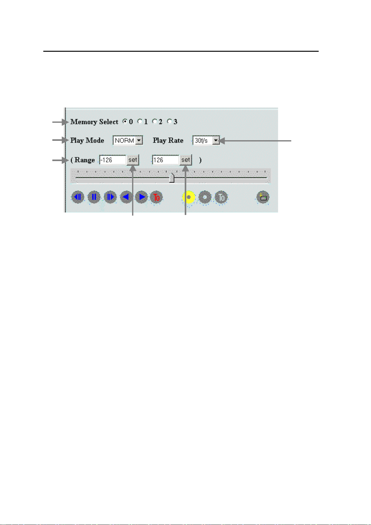
4-4. Playback Operations
This section describes settings related to image playback on the camera.
When recording is completed, the mode changes to STOP mode and the image at the frame
where the trigger was detected (frame T
In addition, the start frame and end frame (the number is offset from the frame (T
displayed in ④ “Range” in the window.
①
0, frame counter = 0) is displayed on the video monitor.
0)) are
②
④
⑤
① Memory Select: If the segment setting is set to two or four under “Record”, select the
memory segment to be played. (If there are two segments, then “0” or
“1” can be selected. If there are four segments, then, “0”, “1”, “2”, or
“3” can be selected.)
② Play Mode: Select whether to play once (NORM) or repeatedly (LOOP).
③ Play Rate: Set the playback speed for PLAY and LOOP modes. The speed when
recording ends is 30f/s. The following settings are available for NTSC:
1, 2, 3, 5, 10, 15, 30, 60, 120, 240, 480, 960 f/s. If the setting is to
60f/s or higher, images are displayed as sampling frames.
④ Range: Set the playback range. At the time recording is completed, recording
range is the range of the memory. This setting is available for
playback frame range and the frame range for saving images to the
PC. When Memory Select is changed, the Range setting is restored
to its setting at the time that record ended.
⑥
Fig. 4-4-1
③
38
Page 51

4-4-1. Playback (Forward)
This section describes how to forward playback recorded images on the camera.
To playback images, change to STOP mode then click PLAY button.
Playback starts at the currently displayed frame. You can check recorded phenomena
with moving image on the video monitor.
Playback continues until memory end is reached (or until playback range end if a
playback range has been set), after which still images are played back (STOP mode).
Click STOP button to stop playback.
Playback (frame feed) speed is set by Play Rate (the standard setting for NTSC is 30
f/s).
If Play Mode is set to NORM, video is played back once until the end of memory or until
the end of a specified playback range, after which a still image is played (STOP mode).
4-4-2. Playback (Reverse)
During reverse playback, playback is the same as forward playback, except that the
playback moves in reverse and towards memory start. Playback continues until memory
start is reached (or until playback range start if a playback range has been set), after which
still images are played back (STOP mode).
4-4-3. LOOP playback
You can set LOOP as the playback mode in order to repeatedly observe desired
phenomena. In this mode, playback continues until memory end.
Click ▼ next to ② “Play Mode”, then select one of the following from the list:
NORM (playback not repeated)
LOOP (playback repeated over the playback range)
39
Page 52
4-4-4. Playback Range
For recording the high-speed phenomena, sometimes it is difficult to record just the desired
phenomena, and large amounts of unneeded phenomena being recorded. Setting a
playback range enables it to play and transfer to the PC just the necessary frames.
Use the following procedure to set playback frame range.
Press STOP button to stop image during moving image playback. A still image is now
played (STOP mode).
Use slide bar or step button to move to the desired start frame, then click the start frame
“Set” button ⑤. This sets the currently displayed frame as the start frame in the
playback range. You can also enter the start frame directly as a number.
Next, use the same procedure to display the end frame, then click on the end frame
“Set” button ⑥. This sets the currently displayed frame as the end frame in the
playback range. You can also enter the end frame directly as a number.
The end frame must be later in the sequence than the start frame.
The playback range is also used as a range for saving data to the PC.
4-4-5. Playback Frame Advance/Back Buttons,
Slide Bar
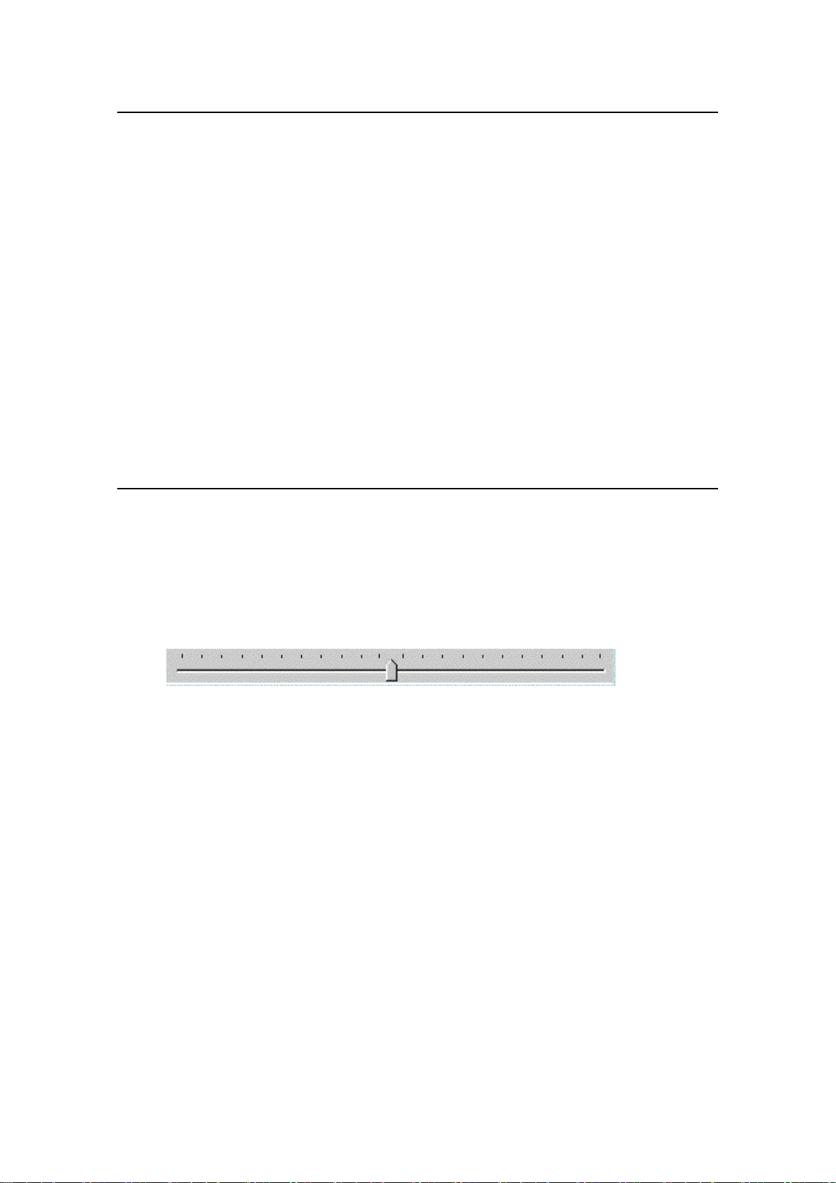
You can use buttons or the slide bar to set the frame number to be displayed on the video
monitor.
When a still image is played (STOP mode), you can use the frame feed buttons (forward
and reverse) to move the currently displayed image (frame) one frame at a time. In addition,
you can move the slide bar to move the currently displayed frame anywhere on the bar.
This feature is useful for finding a desired frame showing the desired phenomena in the
large amounts of video frames.
Fig. 4-4-2
40
Page 53
②
4-4-6. Saving Camera Images to PC
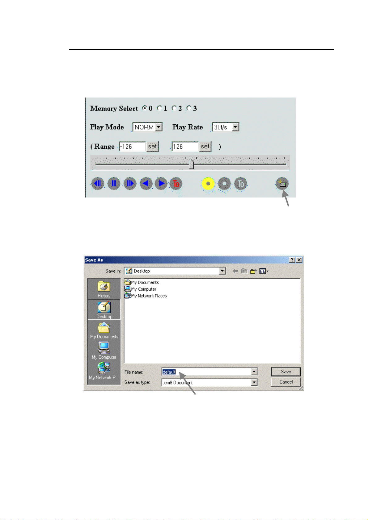
Recorded data can be transferred through the Ethernet interface to a PC for saving.
To save images to a PC, click the ① SAVE button. The frames in the range set as
described in Sec. 4-4-4. will be saved to the PC.
Fig. 4-4-3
①
Click the SAVE button, then the following window appears. Under ② “File name (N)”,
enter the name of the file being saved. Next, click “Save” to start file save process.
Fig. 4-4-4
41
Page 54
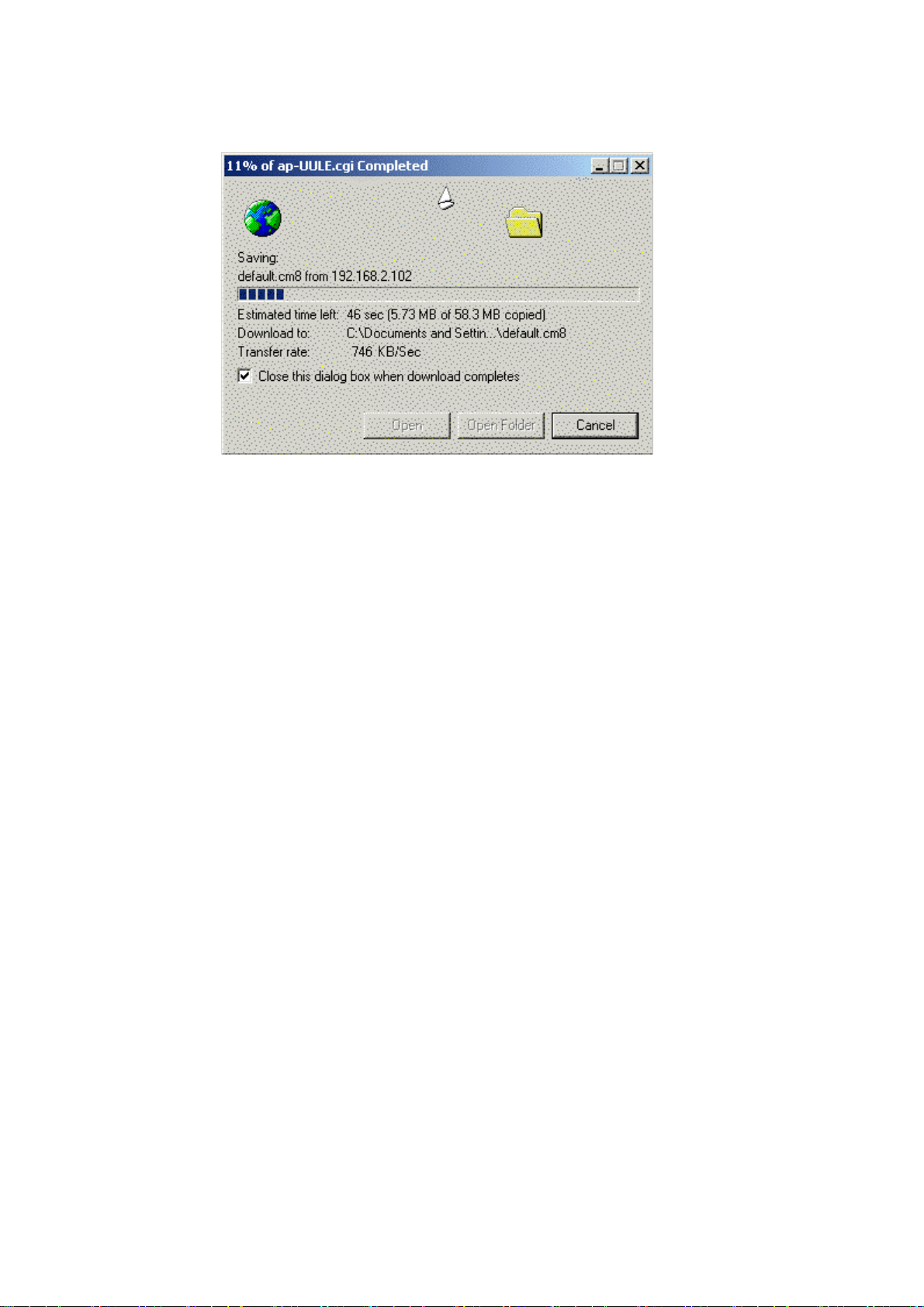
While images are being downloaded from the VFC-1000 to the PC, the following dialog
box is displayed.
Fig. 4-4-5
When the downloading ends, click “Close” (if dialog box is not set to close
automatically).
The camera images will be saved to the PC through the above procedure.
Files with a .cm8 extension which are saved through the above procedure have a
VFC-1000 proprietary format. Section 5 describes how to convert these files to AVI and
other moving image file formats.
42
Page 55

5. Converting Images to AVI Format
Use the included VFCIC image conversion software to display, on the PC, camera image files
which are saved in the VFC-1000 original format (cm8), or to convert them to AVI or BMP file
format.
The VFC-1000’s VFCIC camera image conversion software has the following specifications.
Input: cm8 image files (image files in the VFC-1000’s proprietary format, which are
saved using the VFC-1000’s saving function)
AVI, BMP (display only)
Display: Still image and moving image display of input images in cm8 format, display of
image information (record time and date, image size) and trigger offset frame
numbers, playback of AVI files, and display of BMP files (can be made into
moving images)
Saving: AVI file conversion and save, or BMP file conversion and save of input cm8
format images; saving of conversion information files (part of image
information)
Settings: Display (conversion) range setting, image quality (gain, gamma, white balance,
enhancement), enlarged display ratio, and conversion codec (compression
method) for file saving
43
Page 56
5-1. Installing the VFCIC Camera Image Conversion
Software
The VFCIC camera image conversion software must be installed on your PC to use it. This
section presents the installation procedure.
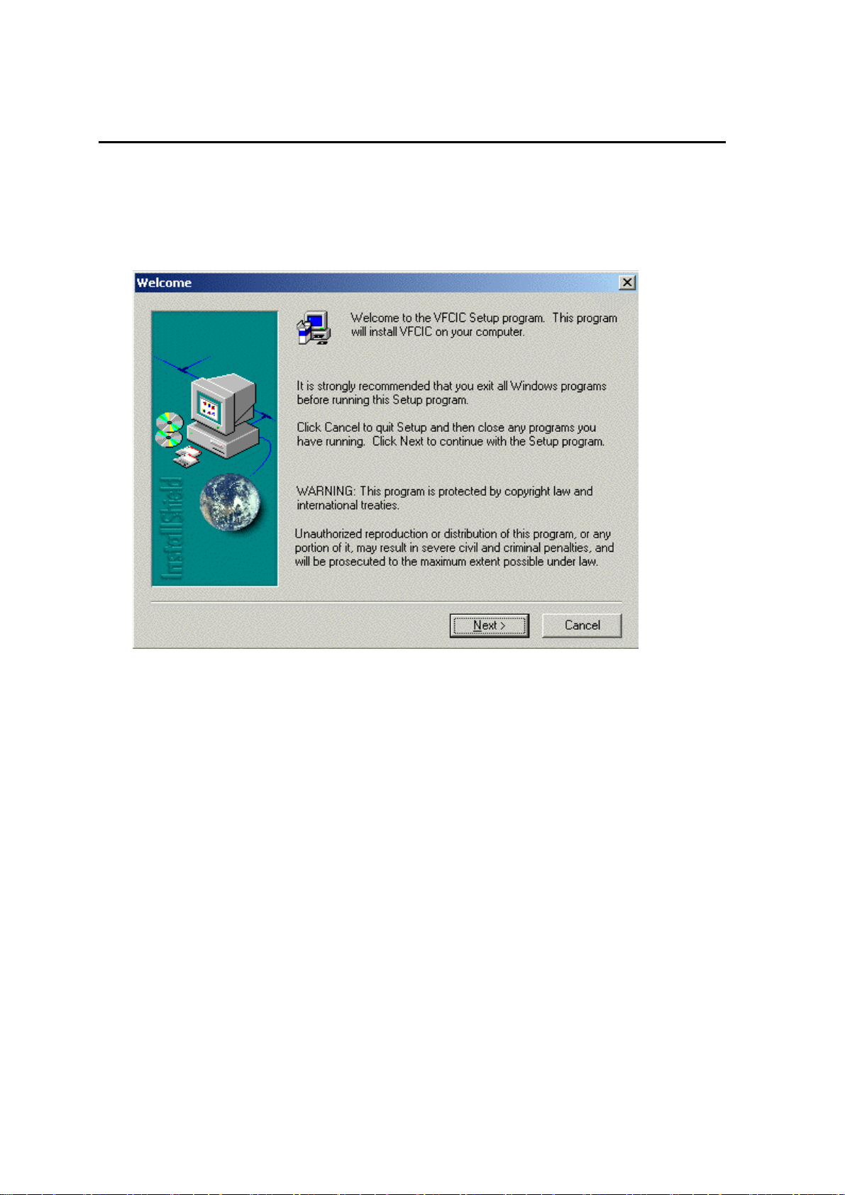
When you insert the included “VFCIC INSTALL DISK” in your PC’s CD-ROM drive, the
following window appears:
Fig. 5-1-1
Click ‘Next’.
If this window is not displayed, run the file ¥Disk1¥Setup.exe on the CD.
44
Page 57
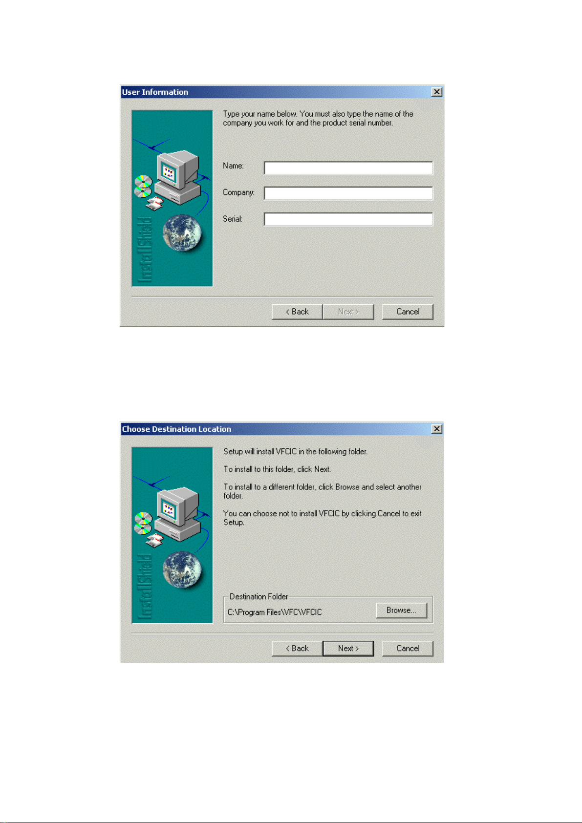
Enter user information
Fig. 5-1-2
Enter a user name, a company name, and a serial number (random figures), then click
‘Next’.
Select an installation directory
Fig. 5-1-3
Click ‘Next’.
45
Page 58
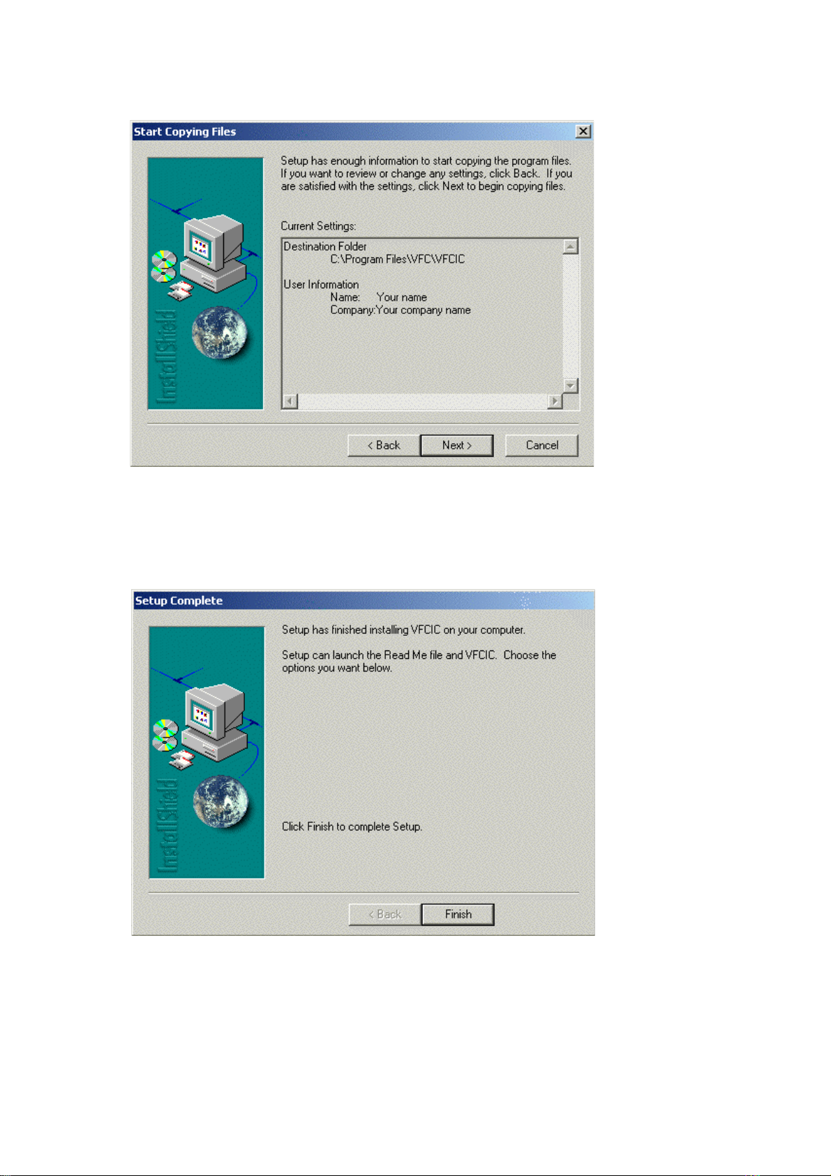
Start file copy process
The file copy process starts when you click ‘Next’.
Finish setup
Fig. 5-1-4
Fig. 5-1-5
Click “Finish” to complete installation process.
46
Page 59
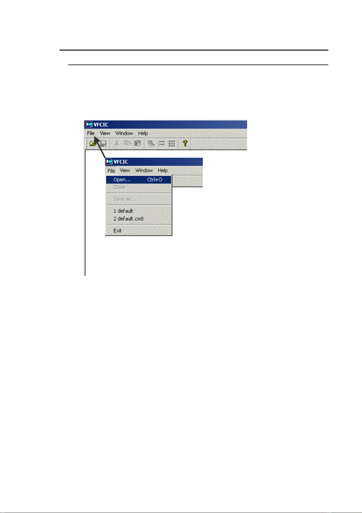
5-2. Operations
5-2-1. Displaying cm8 Images
Use the following procedure to display cm8 image files saved in PC.
Open VFCIC application as follows:
‘Start’ ‘Programs’ ‘VFCIC’ ‘VfcIc’
Click the “File” menu Select ‘Open’.
Fig. 5-2-1
47
Page 60
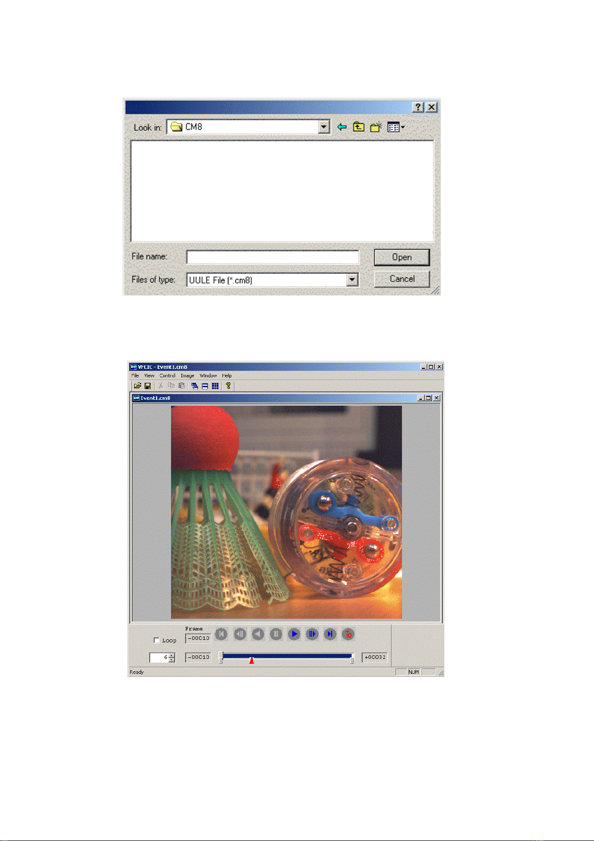
Select a cm8 image file which has been saved from the camera, then click “Open”.
Fig. 5-2-2
The image quality of the displayed cm8 image file can be adjusted on the display. You
can also change the zoom ratio and display screen frame.
Fig. 5-2-3
48
Page 61
t
f
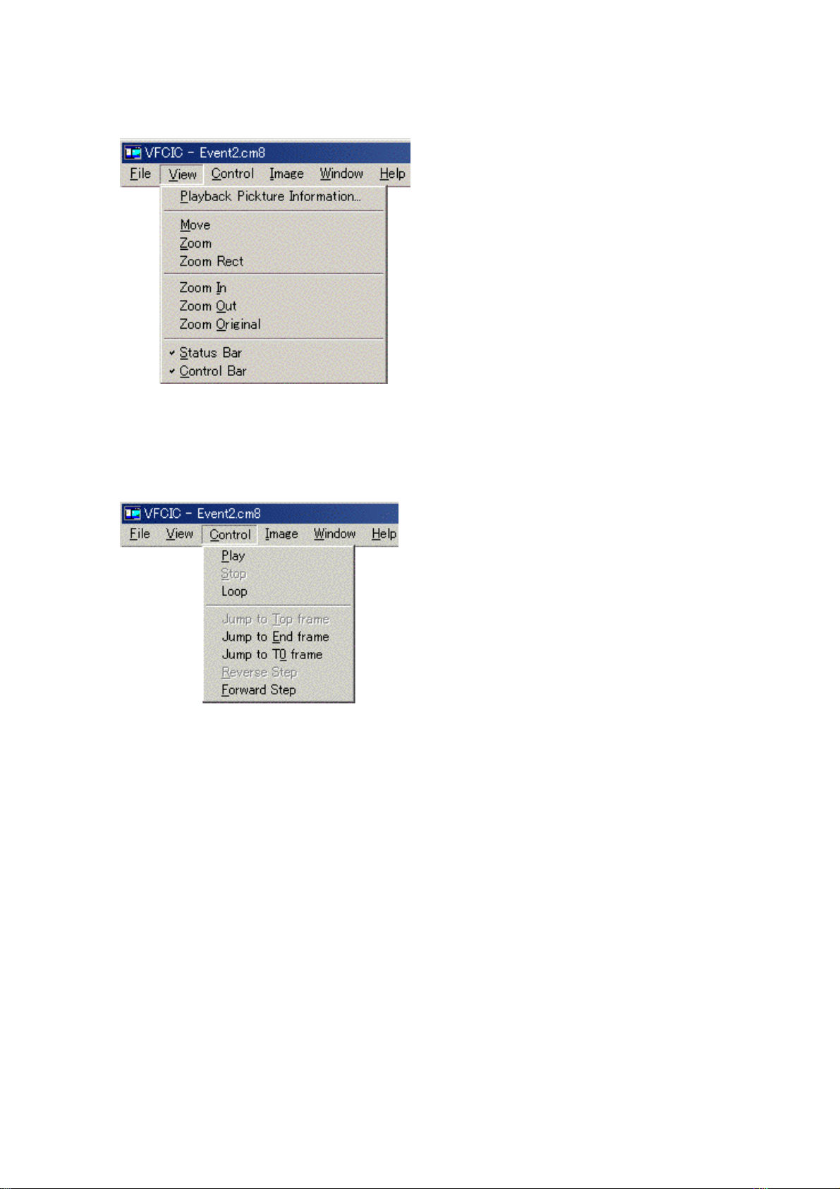
VFCIC menu selections are described below.
① View menu
Playback Picture Information:
Displays image information contained
in currently viewed image data.
Zoom In: Used to enlarge image.
Zoom Out: Used to reduce image.
Zoom Original: Used to restore the
image to original size.
Status Bar: Used to show or hide
status bar at bottom of window.
Fig. 5-2-4
Control Bar: Used to show or hide
control bar (buttons, slide bar) a
bottom of window.
② Control menu
This menu can be used to control
currently displayed frame. (Actions
available on this menu can also be
performed using buttons at bottom o
window.)
Fig. 5-2-5
49
Page 62
t
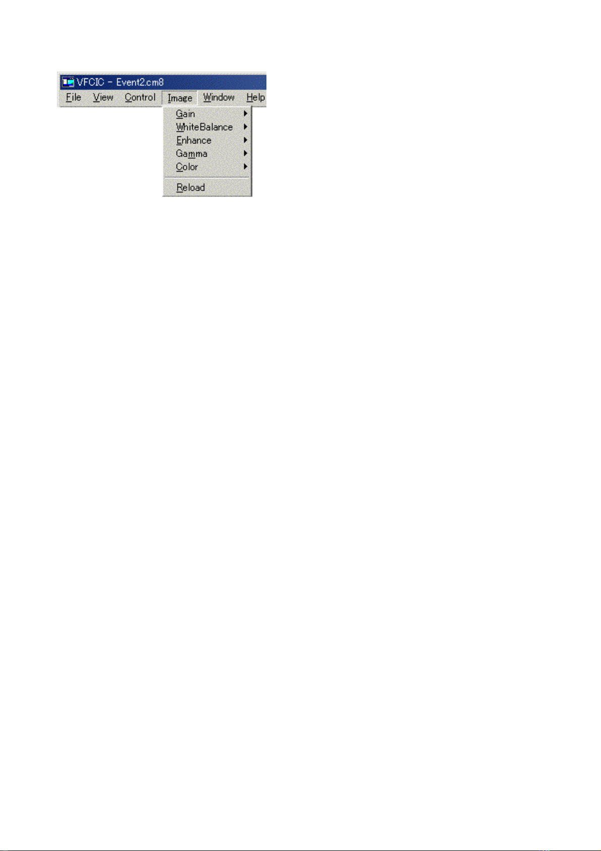
③ Image (image quality adjustment) menu
This menu can be used to make the
following image quality adjustments.
Gain: Display gain (see note) adjust
WhiteBalance: White balance adjust
Enhance: Enhancement adjust
Gamma: Gamma adjust
Fig. 5-2-6
Color: Color saturation adjust
Reload: Restores initial values
(settings in camera)
Gain parameter is different from the
camera gain (which can only be se
during exposure). Initial setting is 0
dB.
Image quality can only be adjusted
on camera image files (cm8 format).
Image quality cannot be adjusted on
AVI files or BMP files.
50
Page 63
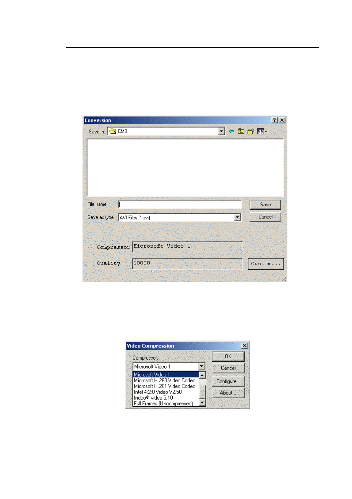
5-2-2. AVI Conversion
Images in cm8 format can be converted to AVI files. The compression function in Microsoft
Windows is used for conversion.
Adjust image quality of the image to be converted to AVI format, and then set save
range.
Use the following procedure: “File” “Save As...” “Save in” “Enter File name”
“Save as type (AVI Files)”
Fig. 5-2-7
You can specify image compression method in the dialog box shown below, which
appears when you click “Custom...”. You can select a compression method from the
displayed list of AVI conversion codec programs contained in your copy of Microsoft
Windows.
Fig. 5-2-8
51
Page 64
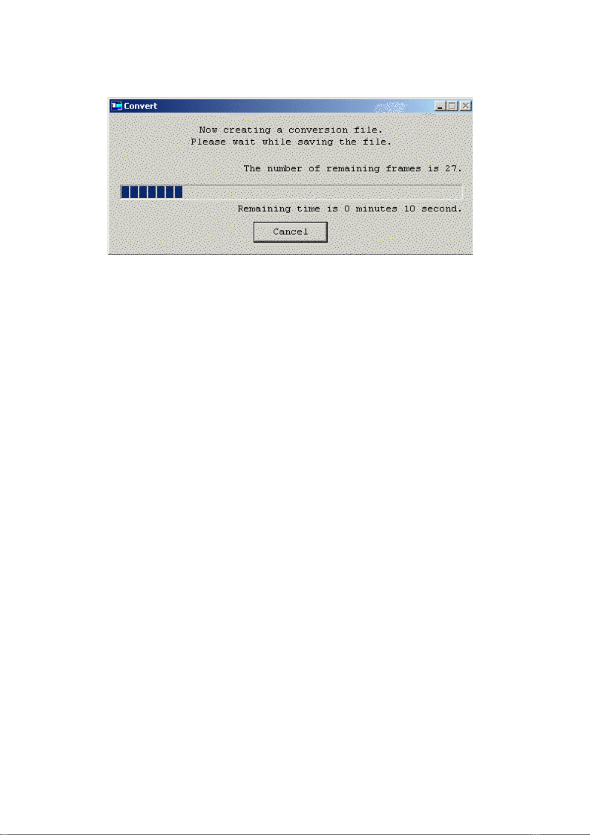
When you select “Save”, all frames in the save range will be converted and saved in one
package.
Fig. 5-2-9
Like ordinary AVI moving image files, converted AVI images which are saved by the
VFCIC camera image conversion software can be easily displayed as moving images
on Windows Media Player.
You cannot specify playback rate on the displaying AVI images in Windows Media
Player.
If the PC’s graphics processing is not fast enough, then the frames in the file may be
displayed as sampling frames.
52
Page 65
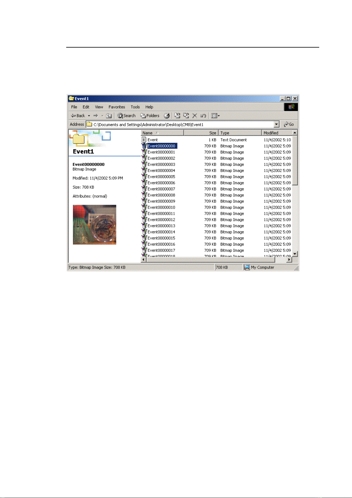
5-2-3. BMP Conversion
In addition to converting images to AVI format, the VFCIC camera image conversion
software can also convert them to bitmap (BMP) files.
The conversion procedure is the same as AVI; select BMP in the “File type” instead of AVI.
The example of saved bitmap files is shown below.
Fig. 5-2-10
53
Page 66
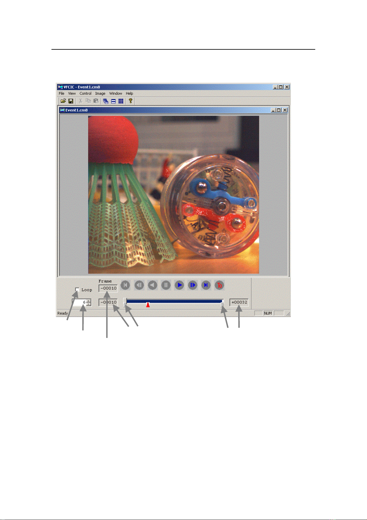
5-2-4. Displaying AVI and BMP Images
AVI and BMP images saved using VFCIC can be displayed with the camera image
conversion software. Multiple BMP files can be displayed as one moving image clip.
In the VFCIC, do the following: ‘File’ ‘Open’ ‘File selection’ Click ‘Open’.
Loop
Playback speed
Currently
displayed frame
Repeat (convert and save)
Start frame
Repeat (convert and save)
End frame
Fig. 5-2-11
54
Page 67
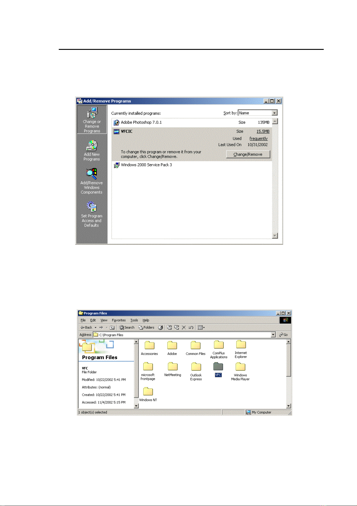
5-3. Uninstalling VFCIC
Before updating to a newer version of the camera’s image conversion software, uninstall the
previous version.
Follow these steps to uninstall it.
Navigate to ‘My Computer’ ‘Control Panels’ ‘Add or Remove Programs’. Select
‘VFCIC’, and then follow the instructions for removal.
Fig. 5-3-1
If an older version remains because you installed the new version without uninstalling the
previous one, delete the folder where you installed the previous program. The installation
folder for the program was specified at the time of installation. The figure below shows an
example where installation was performed in the local disk (C).
Fig. 5-3-2
55
Page 68

6. Record Tips
In order to record high-speed phenomena without problems using a high-speed camera, it is
necessary to select recording speed, shutter speed, lens, and lighting equipment which are
appropriate for the speed of the subject.
6-1. Recording Rate and Shutter Speed
Recording rate: Generally, recording rate is decided by how many times a fast-moving
subject is to be recorded per second. A given fast-moving subject will require a faster
record speed when recorded in a narrow field of view (using a telephoto lens with a long
focal length) than when recorded in a wide field of view (using a wide-angle lens with a
short focal length). For example, if the subject is recorded with a x2 focal length lens, the
recording rate is doubled. Close-ups and microscope shots require a recording rate faster
than the actual speed.
Shutter speed: High-speed phenomena are recorded at higher recording rate. However, if
the subject moves a large amount within the record time for a single frame, the recorded
image will blur. Therefore, in order to record images with as little blurring as possible during
high-speed recording, a high-speed electronic shutter is used for short exposures during a
single frame intervals. As shutter speed increases, image sharpness increases, but the
illumination required on the subject also increases. Therefore, shutter speed is reduced
within the allowable blur range during still image playback. A general guideline is five times
the recording rate (e.g., for recording rate of 250f/s, the shutter speed would be
approximately 1/250 × 5 = 1/1250 second).
56
Page 69
6-2. Lens Selection
Camera sensitivity is insufficient for high-speed recording. Therefore, select the largest
aperture lens possible.
Lens mount: Use a C mount. A CS mount cannot be used. A Nikon F mount lens (for 35
mm photography lens, bayonet mount) may be used with an F-C adaptor.
Lens: Select a megapixel-compatible lens with high resolution, low distortion and high
performance. Use CCD size of 2/3-inch or 1/2-inch.
Close-up shots: If the object distance is shorter than the minimum object distance shown in
the lens catalog, adjust camera focusing by inserting close-up rings between the camera
and the lens. Close-up rings are commercially available in the following sizes. Use a
combination of these sizes to make the adjustment.
Ring thicknesses: 0.5mm, 1.0mm, 5mm, 10mm, 20mm, 40mm
For much closer shots, a special lens with a high optical magnification (capable of
displaying a 10-mm or smaller subject over the entire monitor screen) is required, but
aperture of such lens is small.
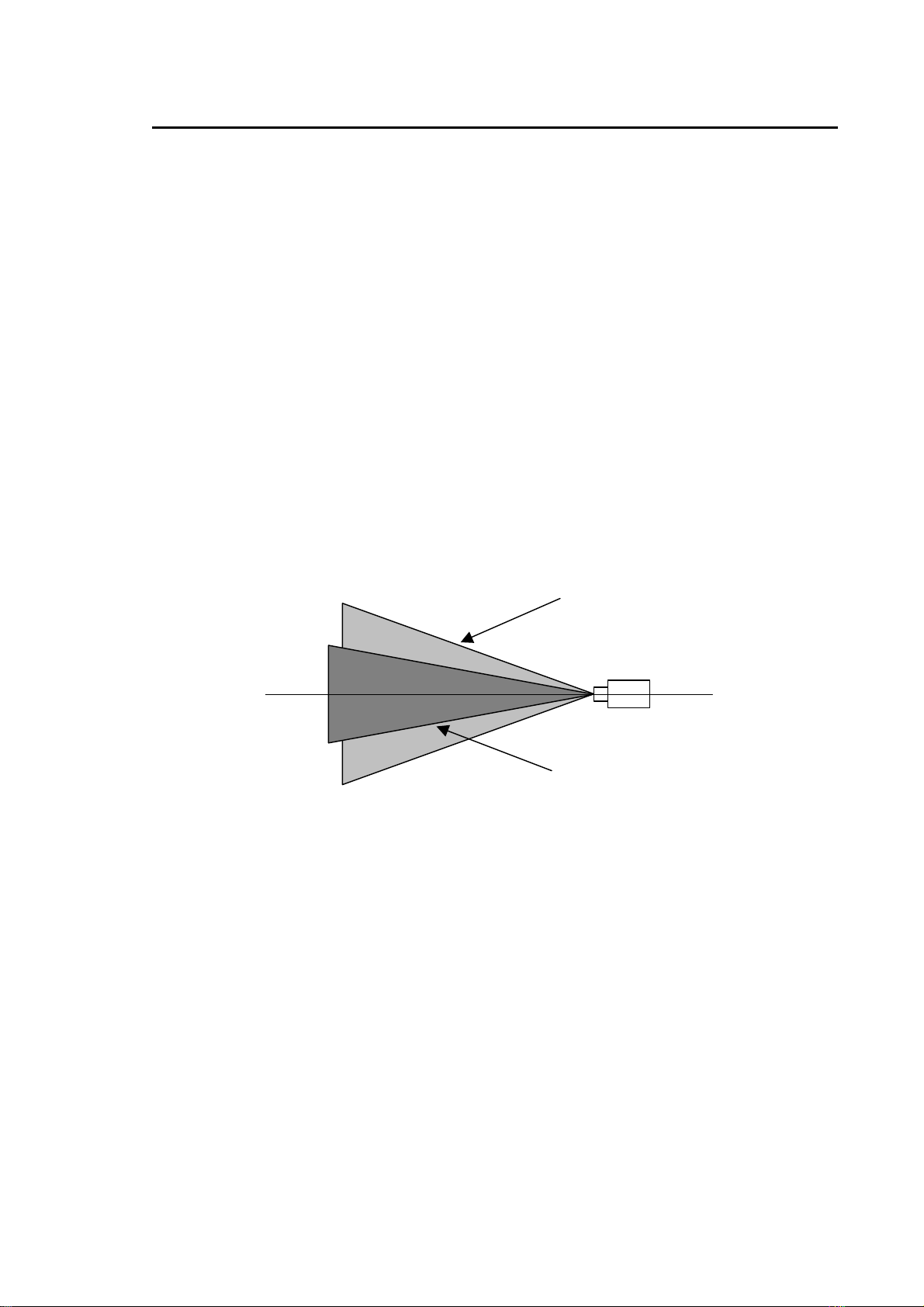
Field of view of VFC-1000: The effective recording area of the VFC-1000’s CCD is reduced
as recording rate is increased, and the record field of view for the given lens is also
reduced in size. For example, in order to record a subject which has a given size at 250 f/s
so that it fills up the entire monitor screen at 1000 f/s, the object distance is half.
Fig. 6-1
250f/s field
1000f/s field
Half the size at 250f/s
57
Page 70

6-3. Lighting
During high-speed record, exposure time is very short — generally no more than 1/100 to
1/1000 the exposure time used with television cameras. Therefore, lighting requirements are
at least 100 to 1000 times greater.
As a general guideline, the light value requirements can be estimated by the following
equation:
(lens aperture)
Light Value of Subject (lx) =
2×shutter speed (in seconds)
(Example) If lens aperture is set to F:4 and shutter speed is 1/1000 second, subject light
value is 4×4/2×0.001=8000 lx.
This equation is merely a guideline for selecting lighting; it is not intended for
determining exposure.
Major types of lighting equipment
Halogen lamps: This is a common type of lighting. A wide variety of inexpensive
products are available, ranging from low illumination to high
illumination. Color temperature is 3000K, which is close to red.
Life is about 200 to 300 hours.
2
Strobe light source: These lights have high brightness, short illumination time (5 to
50 microseconds), and low radiant heat. However, they have an
illumination variance of ±10%. Strobe lights are activated by a
trigger signal from the camera. The light value declines at 500
Hz or more of continuous lighting.
Metal halide: Metal halide lights are well suited to high-speed recording as a
super bright cool light source. They can provide a light value of
1 million lx or higher. In addition, they have a long life (2000
hours), but are expensive.
58
Page 71
7. Specifications and Dimensions
7-1. System Specifications
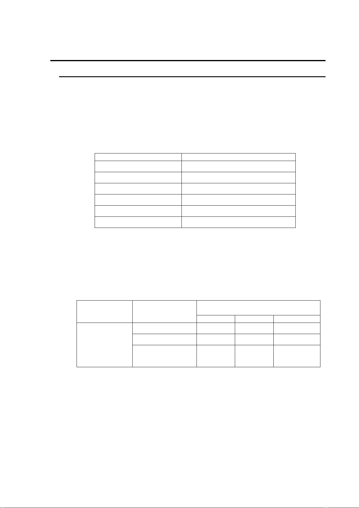
Camera type Integrated
Camera elements 1/3-inch CCD (color or monochrome; Bayer filter for
color)
Pixel size 7.4 µm square pixels
Lens mount C mount
Shutter speeds 1/250, 1/500, 1/1000, 1/2000, 1/5000, 1/10000,
1/20000, 1/50000, 1/100000 second
Resolution/recording rates
Recording rate Image size
50, 125, 250 f/s 512 (h) × 472 (v) pix
500 f/s 512 (h) × 232 (v) pix
1000 f/s 256 (h) × 212 (v) pix
2000 f/s * 256 (h) × 98 (v) pix
4000 f/s * 128 (h) × 88 (v) pix
8000 f/s * 128 (h) × 34 (v) pix
* 2000 f/s or higher are optional specifications.
Sensitivity
Monochrome F4: 2800 lx
Color F4: 6000 lx
(Note: Figures are for 250f/s recording rate, 1/250
second shutter speed, 0dB gain, and gamma OFF,
enhancement OFF.)
Recording time
Recording time
Model Recording rate (f/s)
50 20 seconds 40 seconds 80 seconds
125 8 seconds 16 seconds 32 seconds
VFC-1000 SB/SC
250, 500, 1000
4 seconds 8 seconds 16 seconds**
2000*, 4000*, 8000*
* Record time of 8 seconds and 16 seconds are optional specifications.
** 8 seconds if 8000f/s is applied.
(Internal memory capacity)
(256MB) (512MB) (1GB)
59
Page 72

Record modes Endless record
Trigger options Start, Center, End
Trigger modes External trigger, PC control
Video settings
Gain –4dB, 0dB, +6dB, +12dB, +18dB
Gamma OFF, LOW, HIGH
White balance Approximately 3000K, Approximately 5000K,
Approximately 9000K
Video output
Television standard Conforms to NTSC or PAL (factory default)
Output jacks RCA pin jack (composite video)
S jack (Y/C separation)
Display modes Live (before recording and during recording),
and playback
Video display frame rates Live: 30 f/s (NTSC)
Playback: 1 — 15, 30, 60 — 960 f/s (NTSC)
Live: 25 f/s (PAL)
Playback: 1 — 12, 25, 50 — 1000 f/s (PAL)
Frame information display Frame No., recording rate, shutter speed, gain,
camera ID, Scene No.
Digital I/F Ethernet 100Base-TX
Remote control RS-232C
Using remote control unit (optional)
Trigger input LVTTL level or make contact
(1 kΩ or less, including cable)
Synchronized record
2 units connected Master/slave configuration
3 or more units connected Star configuration using synchronous signal
distributor (optional)
60
Page 73

Power supply voltage 16V DC±5%
Consumption 0.6 A
Operating temperature range 5°C — 40°C
Operating humidity range 10% — 95% (no condensation)
Storage temperature range –5°C — 45°C
Storage humidity range 10% — 95% (no condensation)
External dimensions 75 (W) × 75 (H) × 176 (D) mm
Weight Approximately 1 kg
Applicable standards CE, FCC
61
Page 74
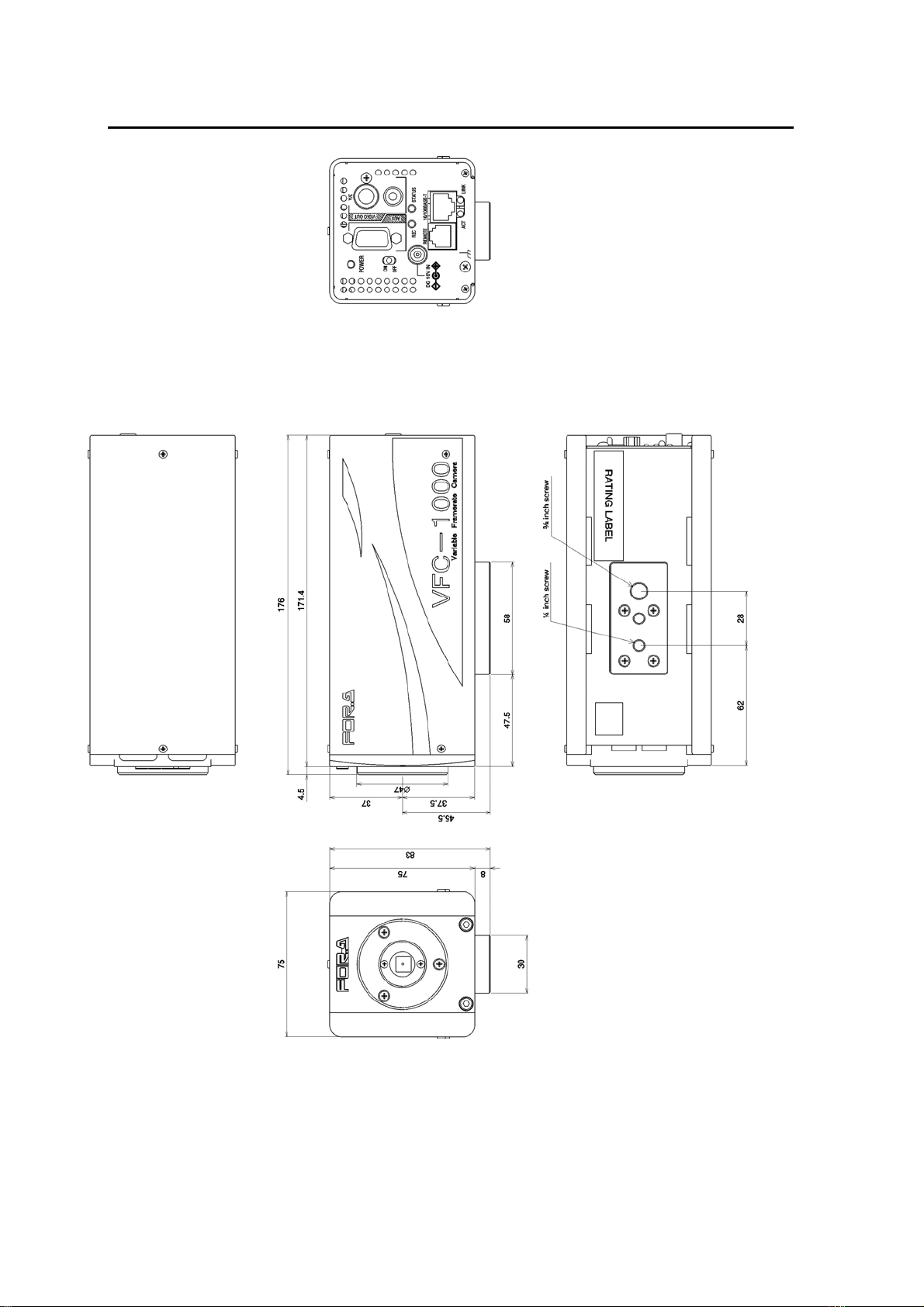
7-2. External Dimensions
(All dimensions shown in mm.)
62
Page 75

Warning
This equipment has been tested and found to comply with the limits for a
Class A digital device, pursuant to Part 15 of FCC Rules. These limits are
designed to provide reasonable protection against harmful interference
when the equipment is operated in a commercial environment. This
equipment generates, uses, and can radiate radio frequency energy and,
if not installed and used in accordance with the instruction manual, may
cause harmful interference to radio communications. Operation of this
equipment in a residential area is likely to cause harmful interference, in
which case the user will be required to correct the interference at his own
expense.
Page 76

03/01/2010 Printed in Japan
FOR-A COMPANY LIMITED
Head Office : 3-8-1 Ebisu, Shibuya-ku, Tokyo 150-0013, Japan
Overseas Division Phone: +81 (0)3-3446-3936, Fax: +81 (0)3-3446-1470
Japan Branch Offices : Osaka/Okinawa/Fukuoka/Hiroshima/Nagoya/Sendai/Sapporo
R&D/Production : Sakura Center/Sapporo Center
FOR-A America Corporate Office
11155 Knott Ave., Suite G&H, Cypress, CA 90630, USA
Phone: +1 714-894-3311 Fax: +1 714-894-5399
FOR-A America East Coast Office
Two Executive Drive, Suite 670, Fort Lee Executive Park, Fort Lee NJ 07024, USA
Phone: +1 (201) 944-1120 Fax : +1 (201) 944-1132
FOR-A America Distribution & Service Cente r
2400 N.E. Waldo Road, Gainesville, FL 32609, USA
Phone: +1 352-371-1505 Fax: +1 352-378-5320
FOR-A Corporation of Canada
346A Queen Street West, Toronto, Ontario M5V 2A2, Canada
Phone: +1 416-977-0343 Fax: +1 416-977-0657
FOR-A Latin America & the Caribbean
5200 Blue lagoon Drive,
Suite 760, Miami, FL 33126, USA
Phone: +1-305-931-1700 Fax: +1-305-264-7890
FOR-A UK Limited
UNIT C71, Barwell Business Park, Leatherhead Road, Chessington Surrey, KT9 2NY, UK
Phone: +44 (0)20-8391-7979 Fax: +44 (0)20-8391-7978
FOR-A Italia S.r.l.
Viale Europa 50 20093, Cologno Monzese (MI), Milan, Italy
Phone: +39 02-254-3635/6 Fax: +39 02-254-0477
FOR-A Corporation of Korea
801 Dangsan Bld., 53-1 Dangsan-Dong, Youngdeungpo-Gu, Seoul 150-800, Korea
Phone: +82 (0)2-2637-0761 Fax: +82 (0)2-2637-0760
FOR-A China Limited
708B Huateng Building, No. 302, 3 District, Jinsong, Chaoyang, Beijing 100021, China
Phone: +86 (0)10-8721-6023 Fax: +86 (0)10-8721-6033
*The contents of this manual are subject to change without notice.
 Loading...