

Page 1
OPERATION
MANUAL
MV-40F(A)
Multi Viewer
nd
Edition
2
S/N 9075301 - Higher
Page 2

Page 3
Precautions
Important Safety Warnings
[Power]
Caution
Stop
[Grounding]
Caution
Hazard
Operate unit only on the specified supply voltage.
Disconnect power cord by connector only. Do not pull on cable portion.
Do not place or drop heavy or sharp-edged objects on power cord. A damaged cord
can cause fire or electrical shock hazards. Regularly check power cord for
excessive wear or damage to avoid possible fire / electrical hazards.
Ensure unit is properly grounded at all times to prevent electrical shock hazard.
Do not ground the unit to gas lines, units, or fixtures of an explosive or dangerous
nature.
[Operation]
Hazard
Hazard
Do not operate unit in hazardous or potentially explosive atmospheres. Doing so
could result in fire, explosion, or other dangerous results.
Do not allow liquids, metal pieces, or other foreign materials to enter the unit. Doing
so could result in fire, other hazards, or unit malfunction.
If foreign material does enter the unit, turn power off and disconnect power cord
immediately. Remove material and contact authorized service representative if
damage has occurred.
Page 4
[Circuitry Access]
Stop
Hazard
Do not remove covers, panels, casing, or access circuitry with power applied to the
unit! Turn power off and disconnect power cord prior to removal. Internal servicing /
adjustment of unit should only be performed by qualified personnel.
Do not touch any parts / circuitry with a high heat factor.
Capacitors can retain enough electric charge to cause mild to serious shock, even
after power is disconnected. Capacitors associated with the power supply are
especially hazardous. Avoid contact with any capacitors.
Unit should not be operated or stored with cover , panels, and / or casing removed.
Operating unit with circuitry exposed could result in electric shock / fire hazards or
unit malfunction.
[Potential Hazards]
Caution
If abnormal smells or noises are noticed coming from the unit, turn power off
immediately and disconnect power cord to avoid potentially hazardous conditions. If
problems similar to above occur, contact authorized service representative before
attempting to again operate unit.
[Fuse]
Caution
If this product is equipped with a fuse, fuse replacement should only be performed
by qualified personnel. Power off equipment and disconnect power cord prior to
replacement. Replace only with fuse of same type, voltage rating, and current rating
as specified for the unit.
[Backup Battery]
Caution
If this product contains a memory backup battery (either dry cell or rechargeable)
and when it is necessary to replace the battery, have work done by the shop where
you purchased the product.
Page 5
Upon Receipt
Unpacking
The MV-40F is fully inspected and adjusted prior to shipment and can be operated immediately
upon completing all required connections and operational settings.
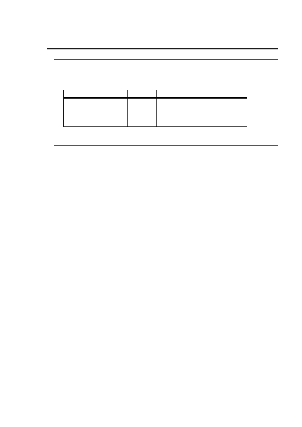
Check your received items against the packing list below.
ITEM QTY REMARKS
MV-40F 1 NTSC or PAL user selectable
AC Cable 1 For unit power supply
Operation Manual 1 This manual
Check
Check to ensure no damage has occurred during shipment. If damage has occurred, or items
are missing, inform your supplier immediately.
Page 6

Page 7

TABLE OF CONTENTS
1. Prior to Starting....................................................................................................... 1
1-1. Welcome..........................................................................................................1
1-2. About the MV-40F............................................................................................. 1
1-3. About This Manual............................................................................................ 2
2. Panel Descriptions.................................................................................................. 3
2-1. Front Panel.......................................................................................................3
2-2. Rear Panel ....................................................................................................... 4
3. Connection Example...............................................................................................5
3-1. Computer Control............................................................................................. 5
3-2. External Alarm Input......................................................................................... 6
3-3. Remote / Alarm Connector............................................................................... 7
3-4. Remote Control................................................................................................ 8
3-4-1. External Time Correction Input............................................................... 8
3-4-2. Remote Control Circuit Diagram............................................................. 9
3-5. Alarm Circuit................................................................................................... 10
4. Operation.............................................................................................................. 12
4-1. Prior to Operation........................................................................................... 12
4-2. Installation Precautions.................................................................................. 12
4-3. Memory Backup ............................................................................................. 13
4-4. Power ON....................................................................................................... 13
4-5. Front Panel Controls ...................................................................................... 14
4-5-1. NTSC / PAL Select............................................................................... 14
4-5-2. Full Screen Mode................................................................................. 15
4-5-3. Full Screen Auto................................................................................... 16
4-5-4. Split Screen Mode................................................................................ 16
4-5-5. Display Mode Quick Reference Chart .................................................. 17
4-5-6. Selecting Split Screen Display.............................................................. 18
4-5-7.Setting Screen Position......................................................................... 19
4-5-8. Setting Channel Assign........................................................................ 20
4-5-9. Freeze Select....................................................................................... 21
4-5-10. Freeze Mode Quick Reference Chart................................................. 23
4-5-11. VTR Record / Playback...................................................................... 24
4-5-12. Zoom Display ..................................................................................... 25
Page 8

4-5-13. Unit Reset...........................................................................................25
4-6. External Alarm Function..................................................................................26
4-7. Video Loss Alarm............................................................................................29
4-8. Alarm Reset ....................................................................................................32
4-9. Alarm Quick Reference Chart.........................................................................33
4-10. Video Loss Quick Reference Chart...............................................................34
5. Main Menu.............................................................................................................36
5-1. Accessing and Changing Menus.....................................................................38
5-2. Time Setup......................................................................................................39
5-3. Alarm / Video Loss..........................................................................................41
5-4. Title/Position ...................................................................................................42
5-4-1. Title / Set...............................................................................................42
5-4-2. Title Position.........................................................................................43
5-4-3. Timer Position.......................................................................................44
5-5. Display............................................................................................................45
5-6. Display Set......................................................................................................46
5-6-1. P-in-P mode..........................................................................................47
5-6-2. Split 2 or 3 Mode...................................................................................48
5-6-3. Channel Assign.....................................................................................49
5-7. Other ...............................................................................................................51
6. RS-232C Remote Control......................................................................................52
6-1. Connection......................................................................................................52
6-2. Communication Parameters ...........................................................................52
6-3 Protocol Flow...................................................................................................52
6-4. Computer Transmit.........................................................................................53
6-5. MV-40F Reply.................................................................................................53
7. RS-232C Control Commands................................................................................54
7-1. Display............................................................................................................54
7-2. Freeze Commands .........................................................................................55
7-3. VTR Mode Commands ...................................................................................55
7-4. Alarm Functions..............................................................................................56
7-5. P-in-P Inset Screen Positioning Commands...................................................56
7-6. Split Screen 2 and 3 Positioning .....................................................................57
7-7. Display Status Request and Reply..................................................................58
7-8. Operation Mode Request and Reply...............................................................58
7-9. P-in-P Inset Screen Position Request and Reply............................................59
Page 9

7-10. Split 2 or Split 3 Screen Request and Reply................................................. 59
8. Specifications & Dimensions................................................................................. 61
8-1. Specifications................................................................................................. 61
8-2. External Dimensions ...................................................................................... 62
8-2-1. Single Unit Rack Mounting................................................................... 62
8-2-1. Single Unit Rack Mounting................................................................... 63
8-2-2. Dual Unit Rack Mounting...................................................................... 63
Page 10

Page 11

1. Prior to Starting
1-1. Welcome
Congratulations! By purchasing the MV-40F you have entered the world of FOR.A and our many
innovative products. Thank you for your patronage and we hope you will turn to FOR.A products
again and again to satisfy your video and audio production needs.
FOR.A provides a wide range of products, from basic support units to complex system
controllers, which have been increasingly joined by products for computer video based systems.
Whatever your needs, talk to your FOR.A representative. We will do our best to be of continuing
service to you.
1-2. About the MV-40F
The MV-40F is a flexible and economical composite input multi viewer with a wide range of
convenient functions. Features include; built-in title generator to identify each source input, four
video inputs with loop thru, one VTR input and output to monitor display recorded material and
one dedicated monitor output. Sequentially freeze video for observation purposes. Ideal for
security monitoring, manufacturing observation, or any application requiring multi viewing of
different locations or different areas within one location.
Features
Accepts and loops thru 4 ea. color or B/W asynchronous composite video signals.
Display camera inputs full screen, 2-split, 3-split, 4-split, or P-in-P.
Split display H or V selectable.
3-split display H or V selectable. 2 one side/1 to other.
3 P-in-P modes, 1 camera full screen + 1, 2 or 3 inset P-in-P displayed.
Input positioning adjustable all display modes except full and quad screen.
Auto sequence between inputs and alarm/lost video detection functions.
Input up to 8 characters per camera channel title, title positionable.
Freeze camera input views as necessary, 2 x zoom views on playback.
All operational parameters on-screen menu set at observation monitor.
Alarm, video loss indications monitor displayed as they occur.
Record video channels in multiple view format modes.
Convenient EIA 1RU half width size.
1
Page 12

1-3. About This Manual
This manual is intended to help the user easily operate the MV-40F and make full use of its
functions during operations. Before connecting or operating your unit, read this operation
manual thoroughly to ensure you understand the product. After reading, it is important to keep
this manual in a safe place and available for future reference.
2
Page 13
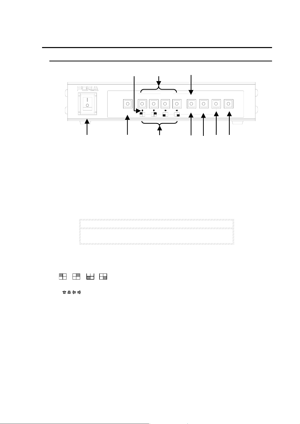
2. Panel Descriptions
2-1. Front Panel
⑤
③
⑥
ON
AUTO
2
SELECT
431MENUVTR
MULTI VIEWER MV-40F
NORMALSPLIT
POWER
OFF
ALARM
RESET
ENTER*FREEZE
①
②
④
⑤
⑦ ⑧ ⑨
① Power switch and indicator
Used to turn unit power ON / OFF.
② AUTO / ALARM RESET
AUTO: Used to switch between full screen displayed channels. When lit, auto sequencing
between full screen displayed channels will commence according to the set dwell time. See sec.
‘5-2. Time Setup’ for details on setting dwell time. Manual switching can also be performed by
pushing this switch.
ALARM RESET: Switch indicator light flashes when alarm is in progress. Push to turn off alarm
buzzer. See important note below concerning external alarms.
IMPORTANT
This switch can not be used to reset alarm status when ALARM
MODE is set to LEVEL.
③ Select 1 - 4
Used to select camera inputs for full screen display when in NORMAL mode. Used to set freeze
operation ON/OFF for corresponding input when in FREEZE mode..
④
Used to zoom in on VTR playback material. See sec. ‘4-5-12. Zoom Display’ for details.
⑤ ENTER
Used to scroll through menu lists and make menu selections.
⑥ SPLIT
Used to turn split mode ON/OFF. Switch indicator lights when SPLIT mode is ON. Split mode
display type (2 split, 3 split, Quad and P-in-P) can be selected by menu operations. See sec. ‘5-5.
Display’ for details.
⑦ NORMAL / FREEZE
Used to set unit to NORMAL or FREEZE mode operation. Switch indicator lights when FREEZE
mode selected. See sec. ‘4-5-9. Freeze Select’ for details.
⑧ VTR
Used for playing back and viewing previously recorded VTR video. Switch indicator lights when
VTR mode selected. See sec. ‘4-5-11. VTR Record / Playback’ for details.
(Continued following page.)
3
Page 14
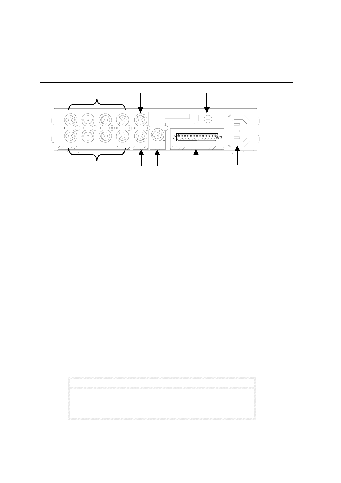
⑨ MENU
Used to access menu mode for setting unit parameters such as title, position, character type, etc.
Switch indicator lights when MENU mode selected. See sec. ‘5. Main Menu’ for details.
2-2. Rear Panel
①
③
⑦
OUT
SER.No
REMOTE/ALARMVTR MONITOR
AC100-240V~50/60Hz IN
IN
1234
OUT
PB IN
VIDEO IN (75 AUTO TERM)
Ω
REC OUT
②
④
⑤ ⑥ ⑧
① VIDEO IN 1 - 4
Used for input of composite video. BNC type connectors.
② VIDEO OUT 1 - 4
Used for output of loopthrough composite video 1-4 inputs (①). These connectors will 75Ω auto
terminate when no loopthrough connection to other system equipment is made. BNC type
connectors.
③ VTR PB IN
Used to input previously recorded VTR material for output to display monitor (MONITOR OUT).
④ VTR REC OUT
Used to output video to VTR for record purposes. Output mode can be set to always quad or the
same mode with the monitor output.
⑤ MONITOR OUT
Used to monitor display selected camera or playback video.
⑥ REMOTE/ALARM connector
Used for remote control connection of a user fabricated remote control device.
Or used for remote control connection to computer.
Also used for external alarm signal input device connection.
⑦ Ground Terminal
Used to ground unit to protect operators against static electricity and / or electrical shock.
⑧ AC IN
Used for connection to AC power source via supplied accessory cord.
IMPORTANT
Unit circuitry is not fuse protected. Unit power cable must not be
directly connected to your power source. Instead, connect to a power
connection unit having either an installed fuse or breaker that can be
easily reached in an emergency.
4
Page 15
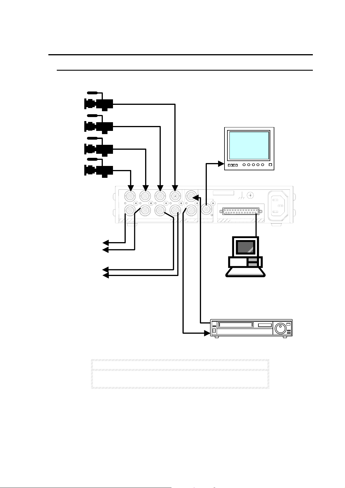
3. Connection Example
3-1. Computer Control
Basic RS-232C interface connection example is given in the figure below.
To other
system
equipment
IN
1234
OUT
Ω
VIDEO IN (75 AUTO TERM)
PB IN
REC OUT
NOTE
OUT
SER.No
REMOTE/ALARMVTR MONITOR
Monitor
AC100-240V~50/60Hz IN
PC
(see note below)
See sec. ‘3-3. Remote / Alarm Connector’ following for
REMOTE/ALARM connector and alarm circuit information.
5
Page 16
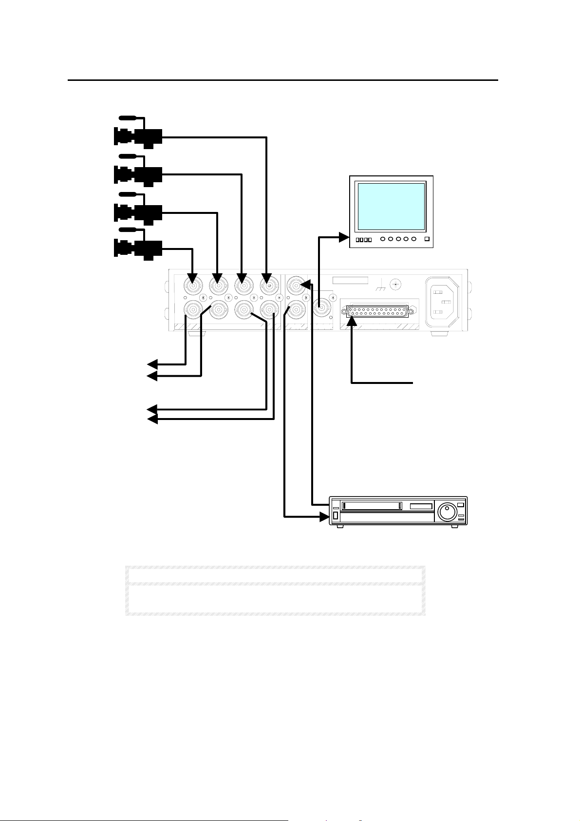
3-2. External Alarm Input
A
Basic alarm connection example is given in the figure below.
To other
system
equipment
IN
1234
OUT
Ω
VIDEO IN (75 AUTO TERM)
NOTE
PB IN
REC OUT
OUT
Monitor
SER.No
REMOTE/ALARMVTR MONITOR
larm signal input
(see note below)
AC100-240V~50/60Hz IN
See sec. ‘3-3. Remote / Alarm Connector’ following for
REMOTE/ALARM connector and alarm circuit information.
6
Page 17
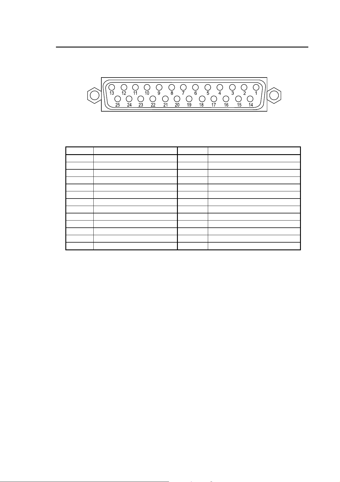
3-3. Remote / Alarm Connector
Connector appearance and pin assignments are as below.
Pin Assignment Table
PIN No SIGNAL PIN No SIGNAL
1 REMOTE AUTO/RST 14 ALARM MAKE
2 REMOTE CH1 15 ALARM COM
3 REMOTE CH2 16 ALARM BREAK
4 REMOTE CH3 17 NOT USED
5 REMOTE CH4 18 RS-232C TXD
6 REMOTE NOR/FRZ 19 RS-232C RXD
7 REMOTE SPLIT 20 RS-232C DTR
8 REMOTE VTR 21 RS-232C DSR
9 ALARM CH1 22 RS-232C RTS
10 ALARM CH2 23 RS-232C CTS
11 ALARM CH3 24 GND
12 ALARM CH4 25 GND
13 ADJUST IN
Pin Functions
REMOTE/ALARM
25-pin D-sub (female)
Pin no. 1 – 8: Remote Control Operations
Pin no. 9 – 12: Alarm Inputs
Pin no. 13: External Time Correction Input
Pin no. 14 – 16: Alarm Outputs
Pin no. 18 – 23: RS-232C Interface Control Signals
To fabricate connection cable for Remote / Alarm Connector:
Use 25-pin D-sub (male) connector assembly.
Assembly part numbers are as given below.
Backshell: D-C4-J11-S1 (JAE)
Connector Core: DB-25PF-N (JAE)
7
Page 18
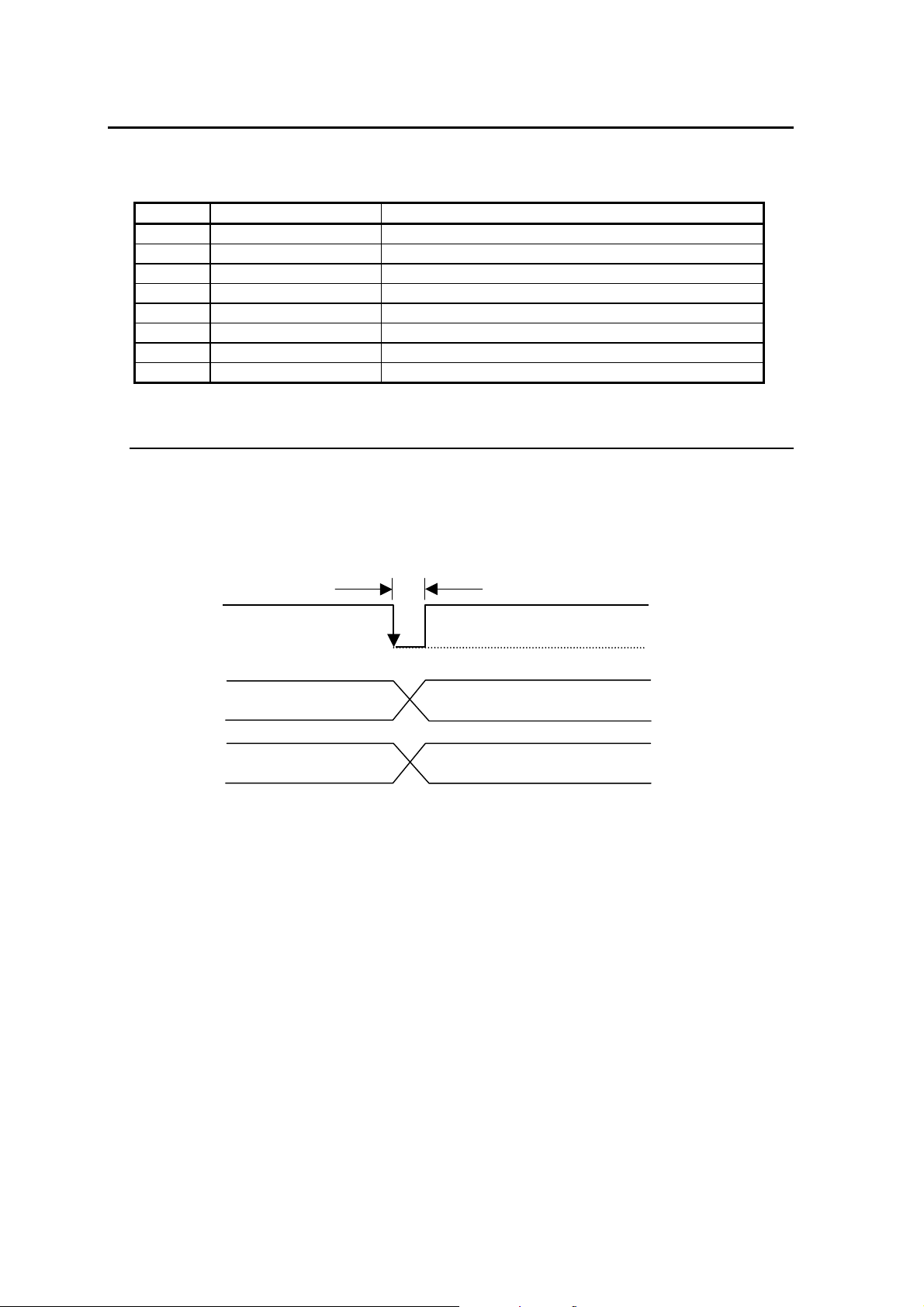
3-4. Remote Control
Adj
p
p
Remote control functions enable switch operations from a remote box are as shown below.
Remote Control Functions
Pin No. SIGNAL Function
1 REMOTE AUTO/RST Same as front panel AUTO/ALARM RESET switch
2 REMOTE CH1 Same as front panel SELECT1 switch
3 REMOTE CH2 Same as front panel SELECT2 switch
4 REMOTE CH3 Same as front panel SELECT3 switch
5 REMOTE CH4 Same as front panel SELECT4 switch
6 REMOTE NOR/FRZ Same as front panel NORMAL/FREEZE switch
7 REMOTE SPLIT Same as front panel SPLIT switch
8 REMOTE VTR Same as front panel VTR switch
3-4-1. External Time Correction Input
Time can be corrected by an external minute pulse signal.
When time correction pulse signal received:
If clock indication is between 1 - 29 seconds, clock is reset to 0 second.
If clock indication is between 30 - 59 seconds, clock is reset to 0 second plus 1 minute.
ust IN
Exam
Exam
le 1).
le 2).
12:10:17 12:10:00
12:30:33 12:31:00
100ms or more
5V
0V
8
Page 19
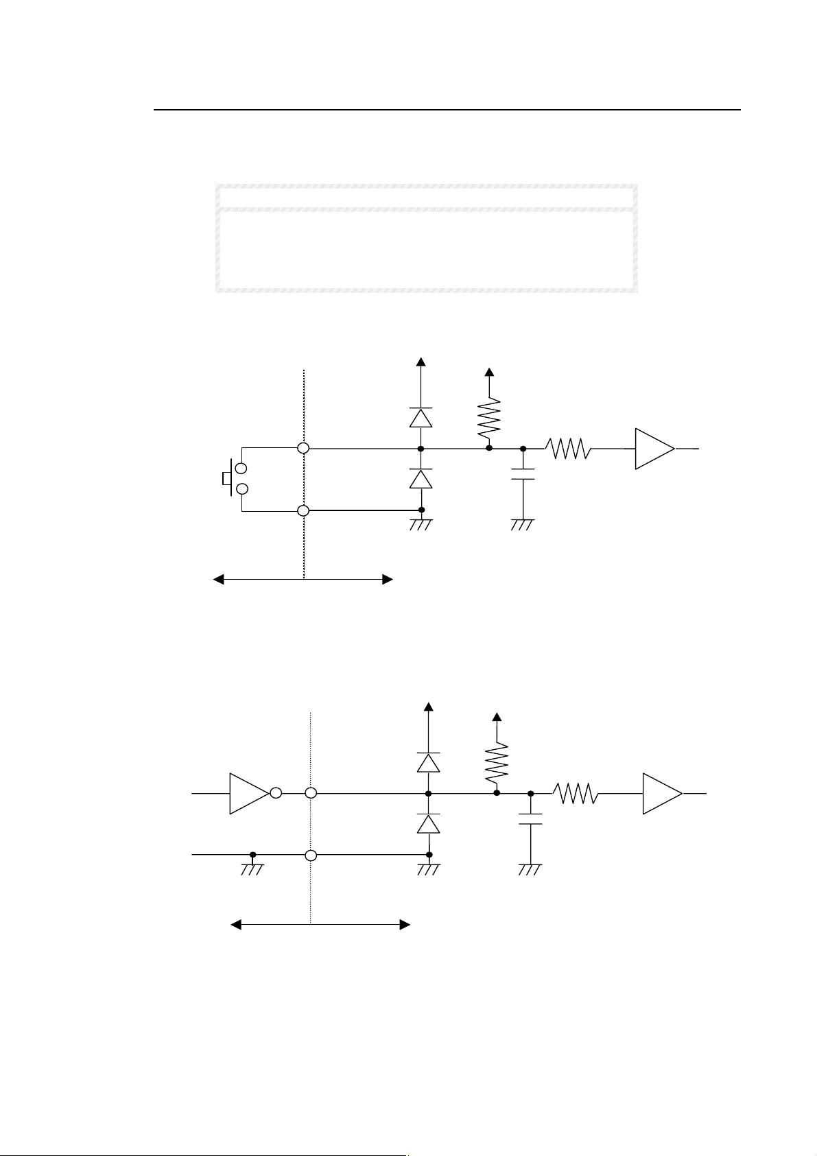
3-4-2. Remote Control Circuit Diagram
Remote control circuit is shown as below with external device examples. See sec. ‘3-3.
Remote / Alarm Connector’ for details on pin assignments.
NOTE
Remote operation is initiated by TTL level negative logic pulse
more than 100ms pulse width.
A delay of more than 100ms between signal inputs is required
for proper remote control operation.
Simple switch as external input device
External device side MV-40F side
TTL level negative logic circuit as external input device
TTL level negative
logic pulse
External device side MV-40F side
Signal input pin
10kΩ
GND (24 or 25 pin)
Signal input pin
(Pin 1 - 9)
10kΩ
GND (24 or 25 pin)
10kΩ
0.01μF
10kΩ
0.01
μF
CMOS Buffer
CMOS Buffer
9
Page 20
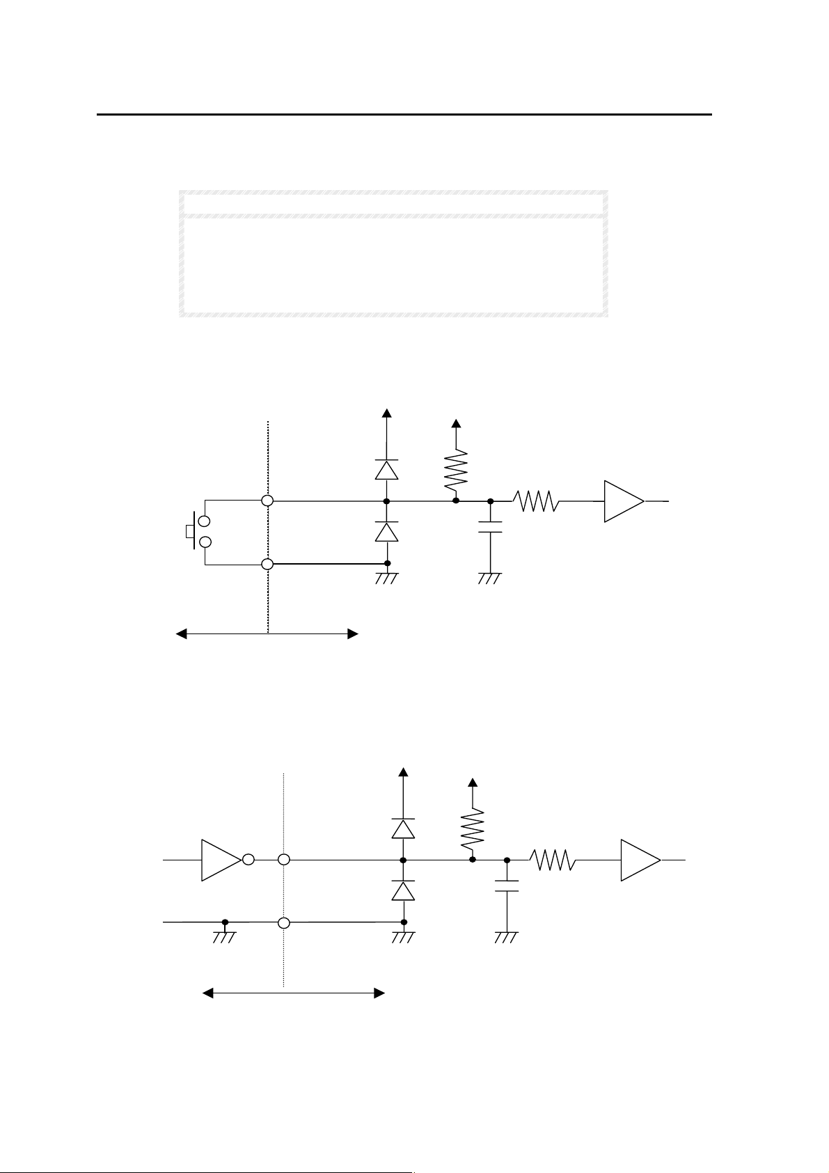
3-5. Alarm Circuit
Alarm input and output circuits with external input device examples are as shown below. See
sec. ‘3-3. Remote / Alarm Connector’ for details on pin assignments.
NOTE
larm initiated by TTL negative logic level signal if menu alarm set
to LEVEL.
Alarm initiated by TTL negative logic pulse signal if menu alarm
set to TRIG (trigger). Pulse width must be more than 100 ms.
See sec ‘5-3. Alarm / Video Loss’ following.
Alarm input circuit with simple switch as external input device
External device side MV-40F side
Alarm input circuit with TTL negative logic circuit as external input device
Signal input pin
GND (24 or 25 pin)
10kΩ
10kΩ
0.01μF
CMOS Buffer
TTL level negative
logic pulse
External device side MV-40F side
Signal input pin
GND (24 or 25 pin)
10
10kΩ
10kΩ
0.01μF
CMOS Buffer
Page 21
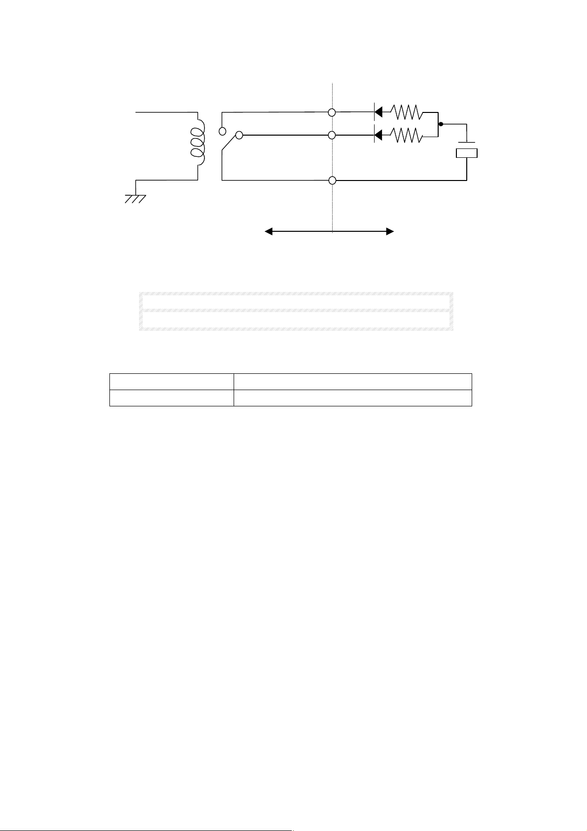
Alarm output circuit with external display device example
MAKE (Pin 14)
BREAK (Pin 15)
Com (Pin 15)
MV-40F side External device side
NOTE
Maximum load: 24VDC 100mA or lower
Alarm output signals
Normal condition BREAK and COM shorted, MAKE is open.
Alarm condition MAKE and COM shorted, BREAK open.
Max load
24VDC
100mA
11
Page 22
4. Operation
4-1. Prior to Operation
Before operating MV-40F, verify the following points:
Verify all cabling connections are securely made.
Verify unit is properly grounded for use in your system.
4-2. Installation Precautions
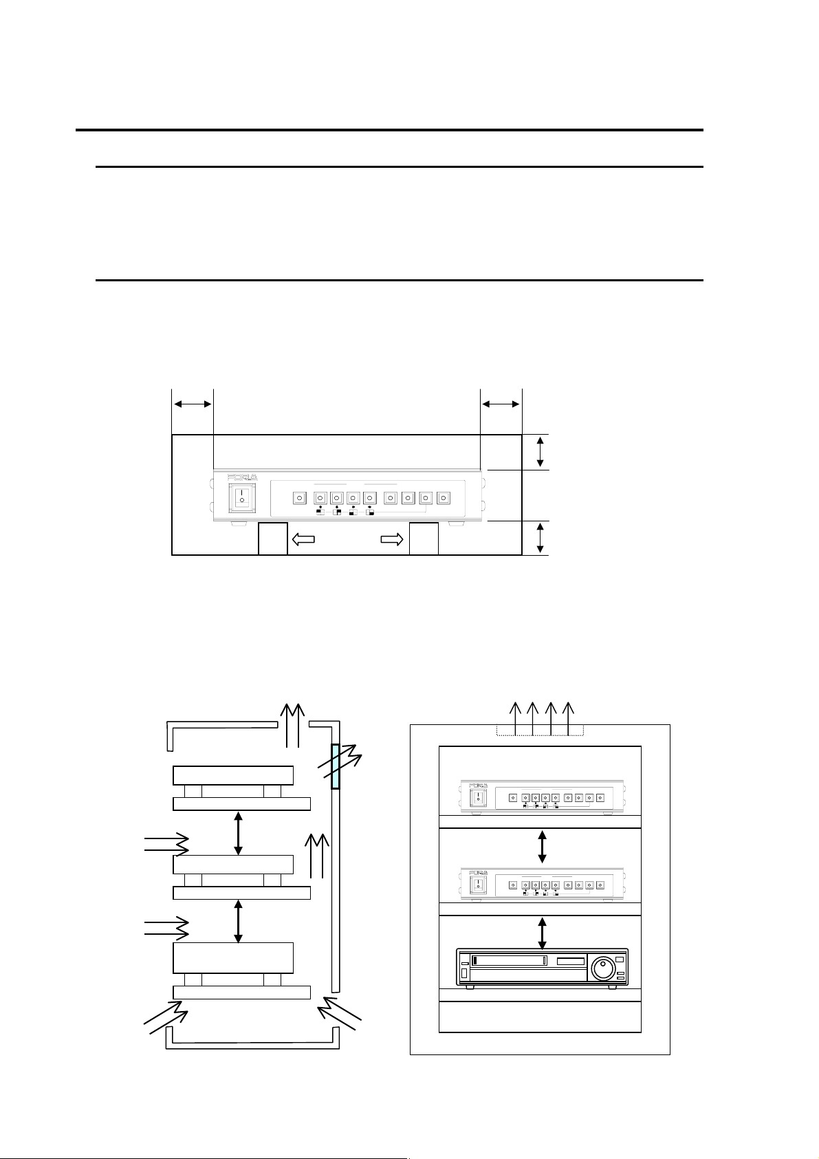
When mounting multiple units be sure not to locate any other electrical unit closer than the
dimensions shown below. If other units are located closer than 44mm, unit temperature may rise
possibly causing operational problems.
Multiple unit installation requirements
50
AUTO
POWER
ON
OFF
ALARM
RESET
Rack mounting instructions
SELECT
2
Spacers
MULTI VIEWER MV-40F
NORMALSPLIT
431MENUVTR
ENTER*FREEZE
50
(Unit:mm)
44
44
① When rack mounting multiple units, install a fan at the top of the rack (as shown below) to
keep operation temperature stable.
② Leave an open space of at least 44mm above each unit.
③ When unit not in use, turn power supply OFF
Hot air
Hot air
MV-40F
Fan
Hot air
MV-40F
MULTI VIEWER MV-40F
SELECT
AUTO
ON
OFF
ALARM
RESET
POWER
2
431MENUVTR
NORMALSPLIT
ENTER*FREEZE
MV-40F
VTR
44mm
44mm
44mm
MV-40F
MULTI VIEWER MV-40F
SELECT
AUTO
ON
OFF
ALARM
RESET
POWER
2
431MENUVTR
NORMALSPLIT
ENTER*FREEZE
44mm
VTR
Cool air
Cool air
Cool air Cool air
Side view
Front view
12
Page 23
4-3. Memory Backup
Date and time data as well as user settings are backed up by lithium battery. The service life of
the battery is about 5-years when unit is used at normal room temperature (around 25 degrees).
When the backup battery needs replacement, 'BACKUP ERROR TIME RESET' will be monitor
displayed. Contact your FOR-A supplier for battery replacement procedures.
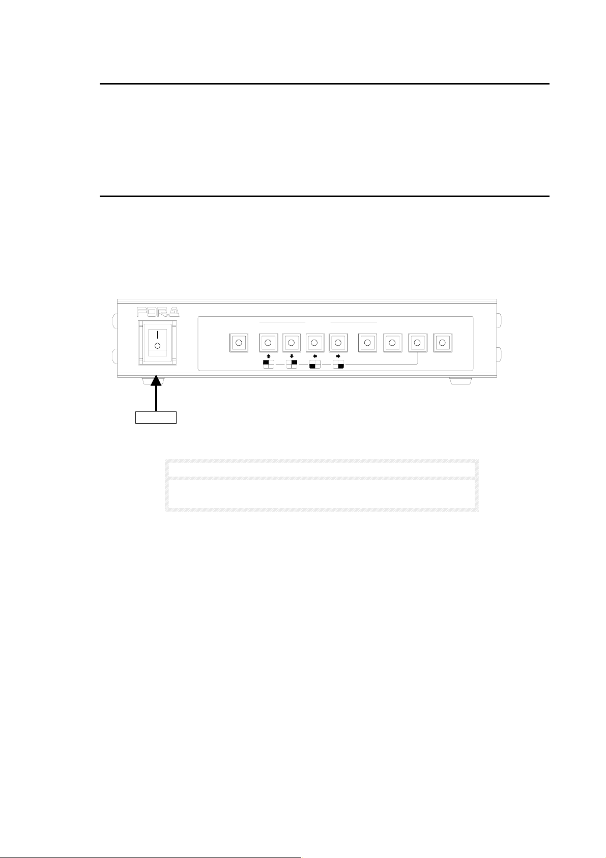
4-4. Power ON
When power is turned on, the last screen setup is monitor displayed. If MENU screen was
monitor displayed or alarm was in progress when power was turned OFF, the previous screen
before the MENU screen or alarm in progress screen will be displayed at power ON.
If first time power ON, initial view will be factory default setting, Quad display.
ON
AUTO
2
SELECT
431MENUVTR
POWER
OFF
ALARM
RESET
POWER
NOTE
MULTI VIEWER MV-40F
NORMALSPLIT
ENTER *FREEZE
Data and time as well as previous user settings will be memory
protected if power switched OFF or loss.
13
Page 24
4-5. Front Panel Controls
The MV-40F front panel controls can be used to select and change operational settings, levels,
parameters and views as well as to make other settings in the operational menu.
4-5-1. NTSC / PAL Select
You can set your MV-40F to either NTSC or PAL format as shown below.
ON
AUTO
POWER
OFF
ALARM
RESET
POWER
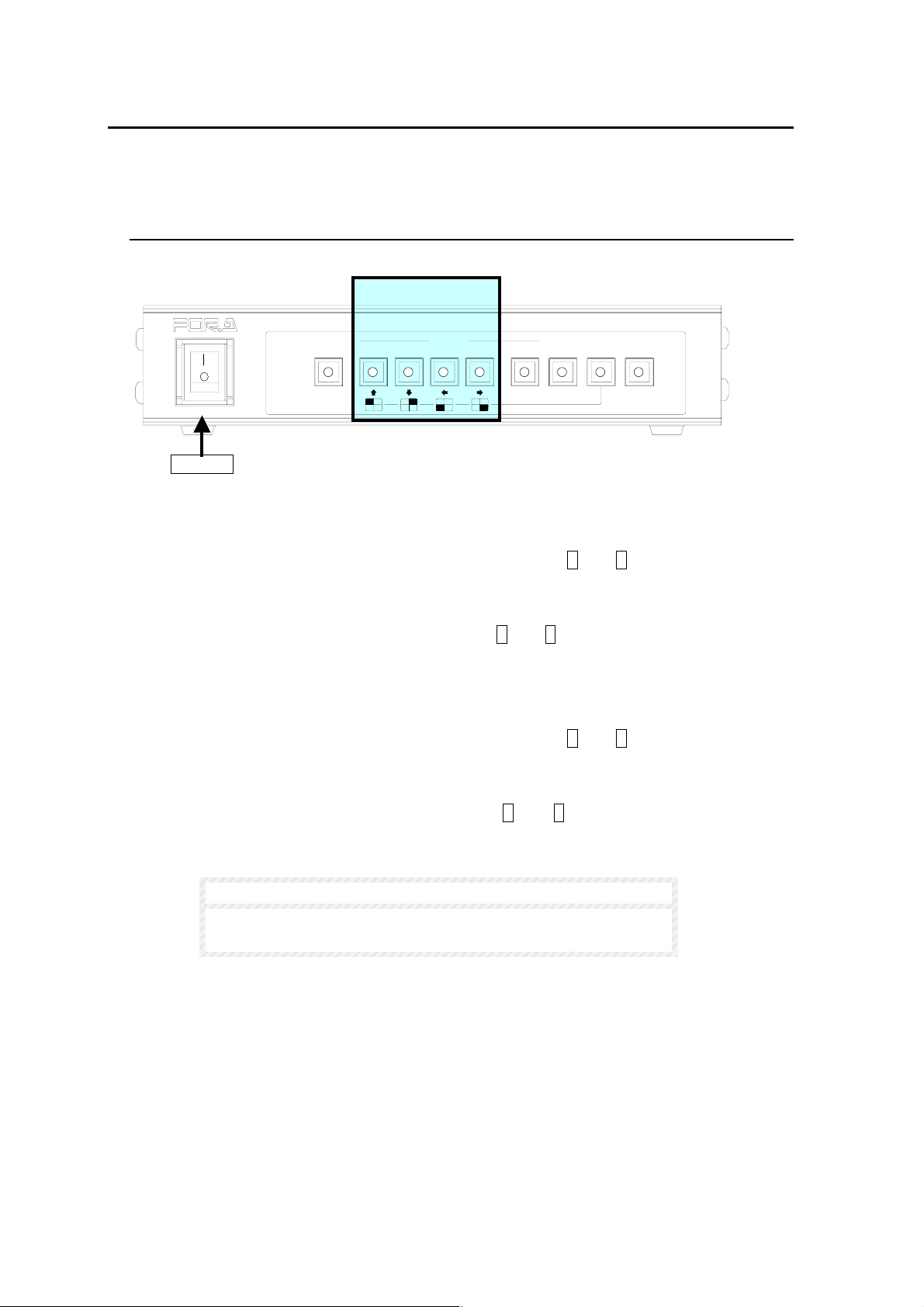
To Set NTSC format:
① With unit power OFF, push and hold SELECT switches 1 and 2.
② Switch unit power ON.
③ Buzzer will sound, release SELECT switches 1 and 2. NTSC will be monitor displayed
and unit will be set for NTSC operation.
To Set PAL format:
① With unit power OFF, push and hold SELECT switches 3 and 4.
② Switch unit power ON.
③ Buzzer will sound, release SELECT switches 3 and 4 . PAL will be monitor displayed
and unit will be set for PAL operation.
SELECT 1 - 4
SELECT
2
NOTE
MULTI VIEWER MV-40F
431MENUVTR
NORMALSPLIT
ENTER *FREEZE
When you change your unit from/to NTSC or PAL format, all
user settings except date/time will be initialized.
14
Page 25

4-5-2. Full Screen Mode
SELECT switches 1 - 4 are used to full screen monitor display one screen image at a time.
For example, if SELECT switch 3 is pushed and video is present at input 3, channel 3 video
will be monitor displayed.
ON
AUTO
POWER
OFF
ALARM
RESET
If a channel without an input connection is selected, the
corresponding screen will go to black.
If VTR or FREEZE operations are in progress, full screen select
can not be performed. In this case, push VTR or FREEZE
switch to cancel VTR or FREEZE operation, then push, SELECT
1 - 4 switches to view full screen display.
When FULL DISPLAY timer is not set to OFF, for example, 10s (10 seconds), full screen
display automatically goes back to split display in 10 seconds, as shown below. Factory
default value of FULL DISPLAY timer is OFF. See sec. ‘5-2. Time Setup’ for FULL DISPLAY
timer value settings.
Quad
Display
SELECT 1
switch
SELECT 1 - 4
SELECT
2
IMPORTANT
Full screen CH1
NOTE
MULTI VIEWER MV-40F
431MENUVTR
NORMALSPLIT
ENTER *FREEZE
10 seconds
passed
Return to
Quad Display
If FULL DISPLAY timer is set to 10s and power is turned OFF
while in full screen display, the initial view is full screen display
when the power is turned ON again, and FULL DISPLAY timer
will be reset to the beginning. The view will return to split view 10
seconds later.
15
Page 26
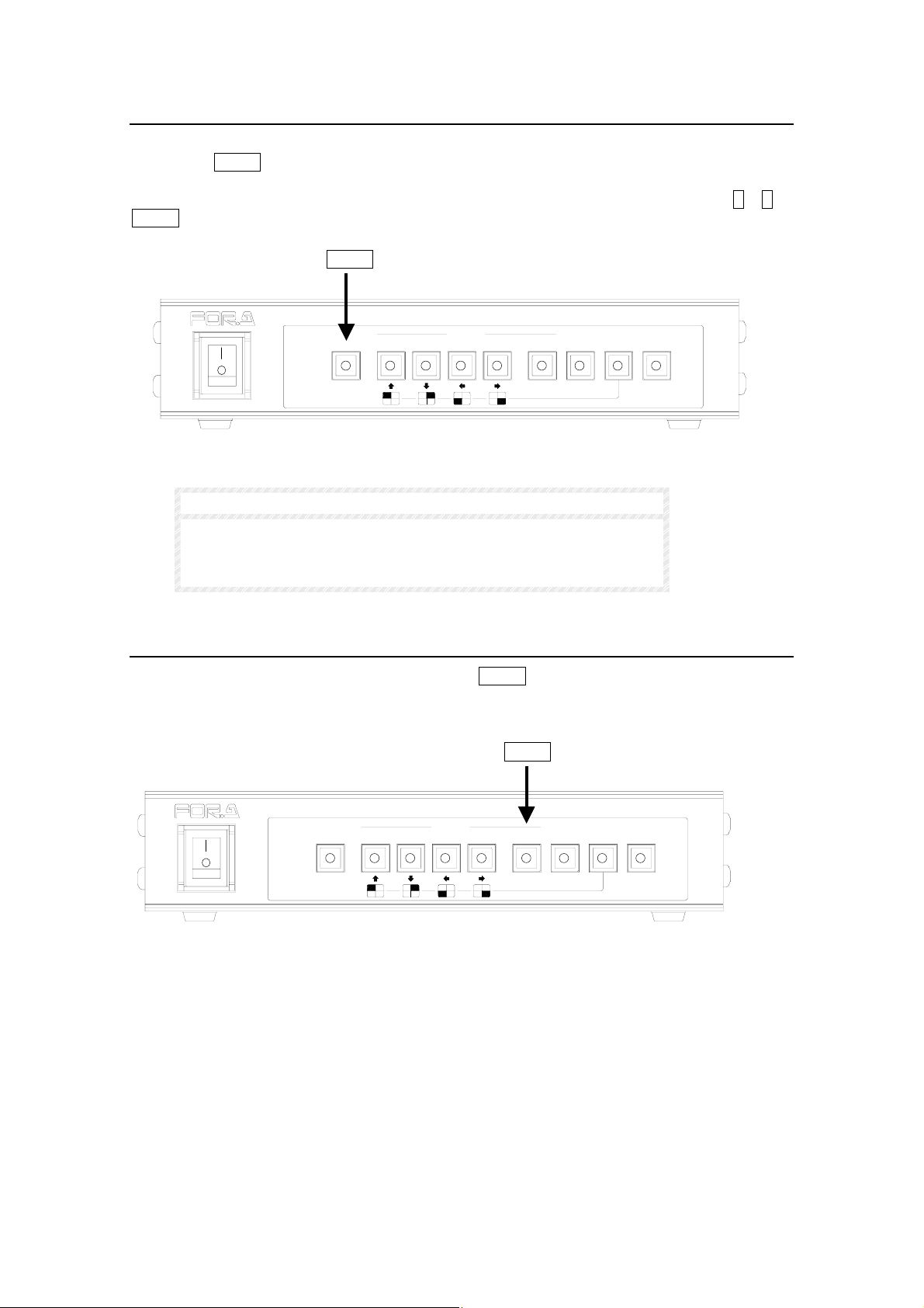
4-5-3. Full Screen Auto
Full screen channels can be automatically switched between to sequentially view all inputs
by pushing AUTO switch when operating in full screen mode. Channels without a video input
connected will be auto skipped. Dwell time between channel switching can be user set. See
AUTO SEQ TIME parameter in sec. ‘5-2. Time Setup’ for details. Pushing SELECT 1 – 4 or
SPLIT switch will cancel Full Screen Auto Display.
ON
POWER
OFF
If input video signals are not synchronized, noise may appear
when switching between channels.
Auto channel select is not available in split screen mode
AUTO
AUTO
ALARM
RESET
SELECT
2
IMPORTANT
MULTI VIEWER MV-40F
431MENUVTR
NORMALSPLIT
ENTER*FREEZE
4-5-4. Split Screen Mode
To change display to split screen mode, push SPLIT switch. Monitor view in split screen
mode must be selected in DISPLAY TYPE menu. See sec. ‘4-5-6. Selecting Split Screen
Display’ for details on setting split screen.
POWER
ON
OFF
AUTO
ALARM
RESET
2
SELECT
SPLIT
MULTI VIEWER MV-40F
431MENUVTR
NORMALSPLIT
ENTER *FREEZE
16
Page 27
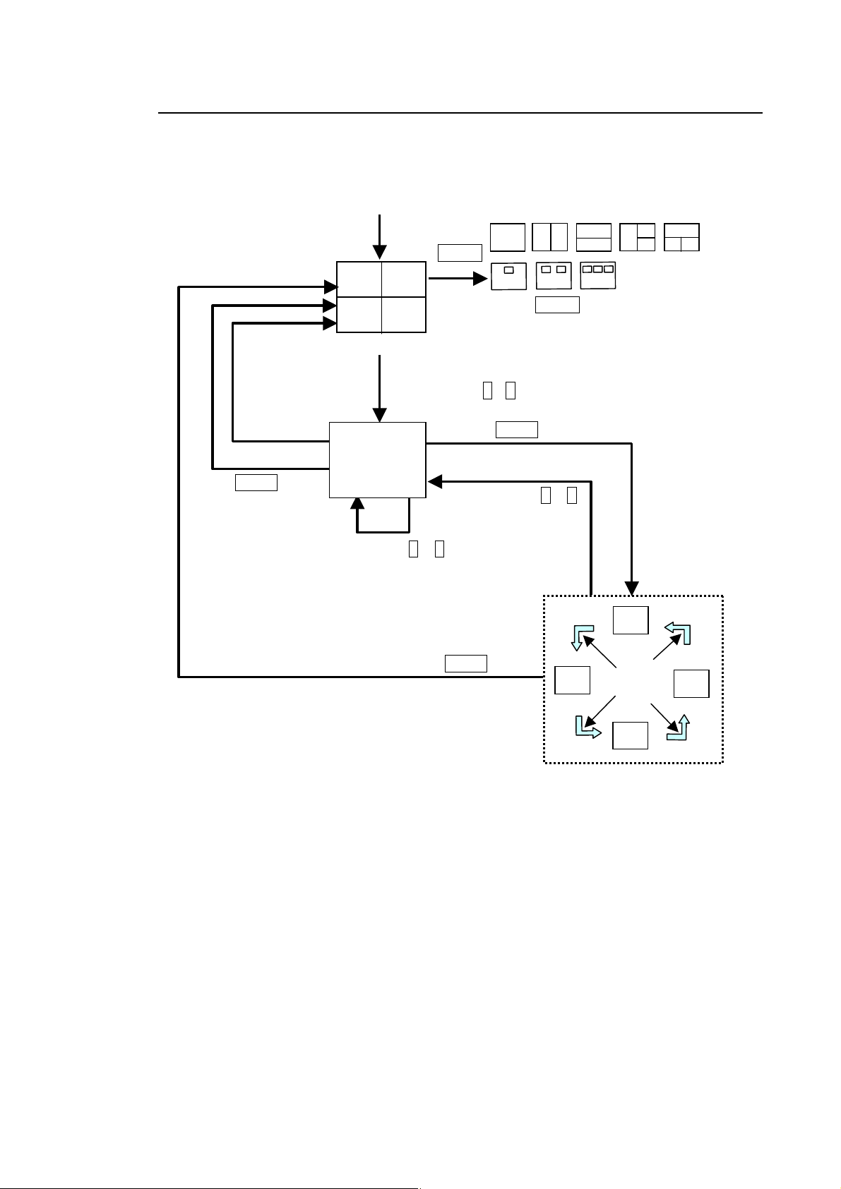
4-5-5. Display Mode Quick Reference Chart
The following quick reference chart is designed to help the operator thoroughly understand
and use the Display functions of the MV-40F.
Full
Display
timer
finished
Push SPLIT Button
POWER ON
(Factory Default)
Push SELECT 1 - 4
Select CH
Full Screen
Push SELECT 1 – 4
Push SPLIT Button
Monitor Display Types
Push
MENU
Push MENU select DISPLAY then
select DISPLAY TYPE and use left
and right switches to select one of the
above Monitor Display Types.
Push AUTO
Push SELECT 1 – 4
CH 2
CH 1
Auto
Sequence
Timer
CH 3
CH 4
17
Page 28
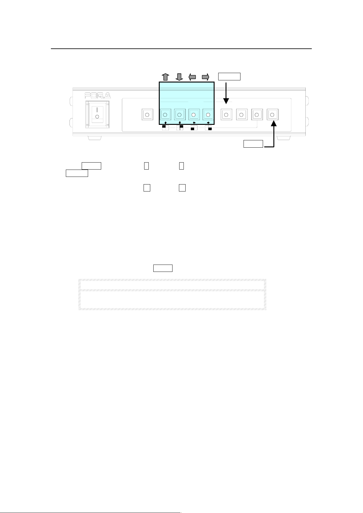
4-5-6. Selecting Split Screen Display
The MV-40F display split screen mode is set in the Display menu. The procedure to do this is
following.
ON
AUTO
SELECT
2
POWER
OFF
ALARM
RESET
① Push MENU switch, use up ↑ and down ↓ switch to move cursor to DISPLAY and press
ENTER switch.
② In DISPLAY TYPE use left ← and right → switch to cycle through available displays:
QUAD: 4 split displays
PIP1: P-in-P 1 (1 full screen and 1 inset screen)
PIP2: P-in-P 2 (1 full screen and 2 inset screens)
PIP3: P-in-P 3 (1 full screen and 3 inset screens)
V2 : Vertical split 2 channels
H2 : Horizontal split 2 channels
V3 : Vertical tri-split, 1 channel left, 2 channels right
H3 : Horizontal tri-split, 1 channel top, 2 channels bottom
③ After making a selection, push MENU switch twice to return to operation mode.
NOTE
ENTER
MULTI VIEWER MV-40F
431MENUVTR
NORMALSPLIT
ENTER*FREEZE
MENU
For more information see sec ‘5. Main Menu’ and sec. ‘5-5.
Display.
18
Page 29
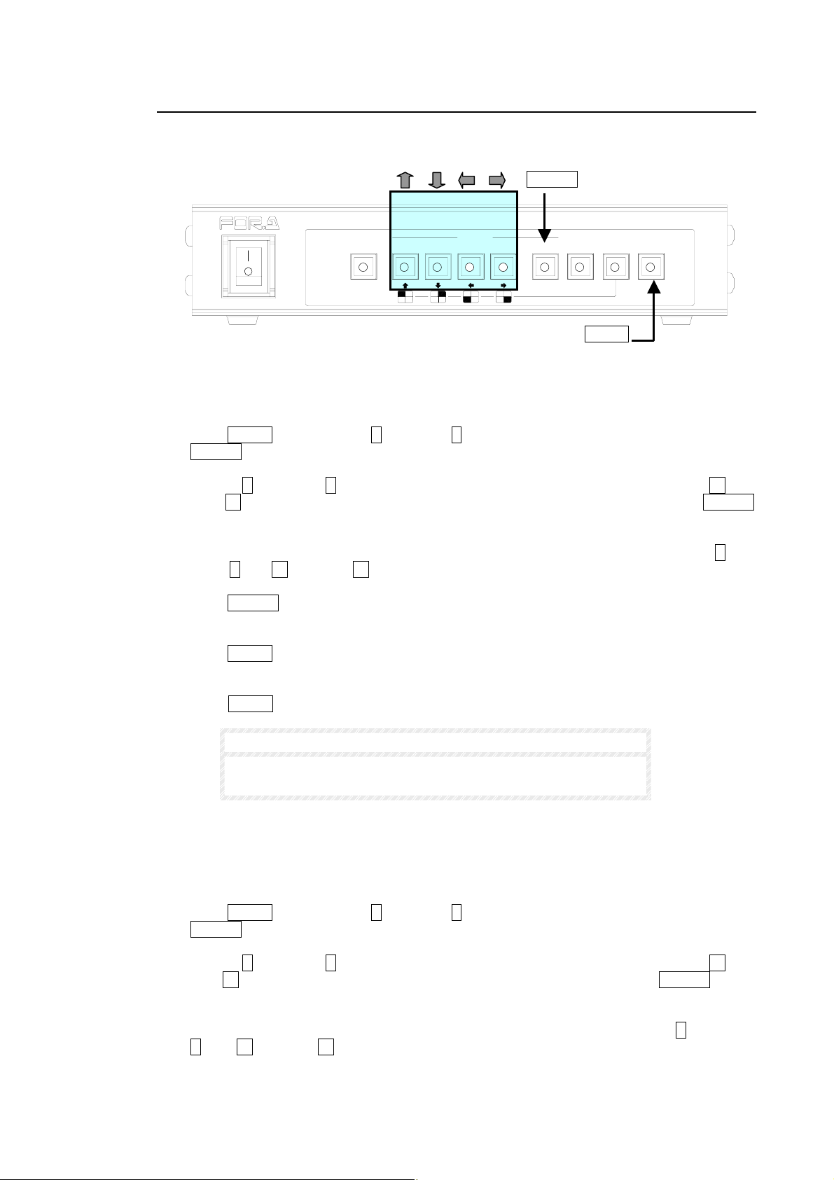
4-5-7.Setting Screen Position
Settings can be made to adjust where P-in-P screen(s) are positioned or to pan / tilt the
picture in split 2 or split 3 screen mode.
ON
AUTO
SELECT
2
POWER
OFF
ALARM
RESET
P-in-P mode
When in P-in-P mode, user can change the display positions of P-in-P inset screens when
corresponding title is flashing.
① Push MENU switch, use up ↑ and down ↓ switch to move cursor to DISPLAY and press
ENTER switch.
② Use up ↑ and down ↓ switch to move cursor to DISPLAY TYPE. Then use left ← and
right → switch to set DISPLAY TYPE to PinP1, PinP2, or PinP3 then push ENTER
switch to go to DISPLAY SET menu.
③ When inset screen title is flashing, you can change the display p osition using up ↑ and
down ↓, left ← and right → switch.
④ Push ENTER switch to select a different P-in-P inset screen (title flashing) to change the
display position.
⑤ Push MENU switch to finish making P-in-P inset screen display position changes and to
return to DISPLAY screen.
⑥ Push MENU switch twice to return to operation mode.
NOTE
ENTER
MULTI VIEWER MV-40F
431MENUVTR
NORMALSPLIT
ENTER*FREEZE
MENU
For more information see sec ‘5. Main Menu’ and sec. ‘5-6.
Display Set’.
Split 2 or 3 mode
When in V2, H2, V3 or H3 mode, only half sized screen view can be adjusted by tilt up/down
or pan left/right. Also when in V2 or H2 mode, the view of title flashing screen can only be
adjusted.
① Push MENU switch, use up ↑ and down ↓ switch to move cursor to DISPLAY and press
ENTER switch.
② Use up ↑ and down ↓ switch to move cursor to DISPLAY TYPE. Then use left ← and
right → switch to set DISPLAY TYPE to V2, H2, V3, H3 mode, then push ENTER switch
to go to DISPLAY SET menu.
③ When screen title is flashing, you can pan/tilt the display position using up ↑ and dow n
↓ , left ← and right → switch.
(Continued following page.)
19
Page 30
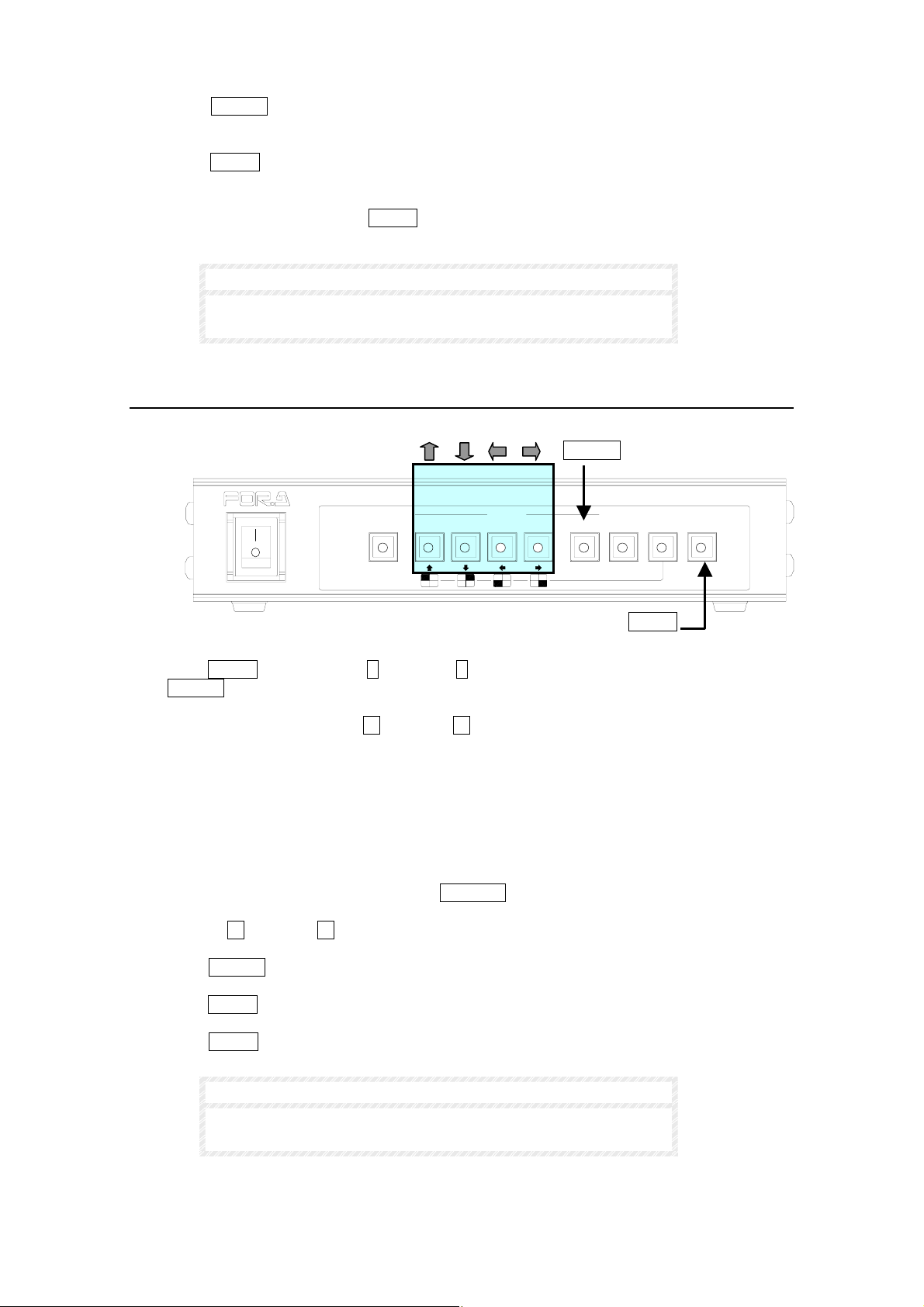
④ Push ENTER switch to select a different half size screen (title flashing) in H2 or V2
mode to change the display position.
⑤ Push MENU switch to finish making split 2 or split 3 screen display position changes
and to return to DISPLAY screen.
⑥ After making settings, push MENU switch to return to operation mode.
NOTE
For more information see sec ‘5. Main Menu’ and sec. ‘5-6.
Display Set’.
4-5-8. Setting Channel Assign
You can assign a channel to each split view as follows.
POWER
ON
OFF
AUTO
ALARM
RESET
SELECT
2
① Push MENU switch, use up ↑ and down ↓ switch to move cursor to DISPLAY and press
ENTER switch.
② In DISPLAY TYPE use left ← and right → switch to cycle through available settings:
PIP1: P-in-P 1 (1 full screen and 1 inset screen)
PIP2: P-in-P 2 (1 full screen and 2 inset screens)
PIP3: P-in-P 3 (1 full screen and 3 inset screens)
V2 : Vertical split 2 channels
H2 : Horizontal split 2 channels
V3 : Vertical tri-split, 1 channel left, 2 channels right
H3 : Horizontal tri-split, 1 channel top, 2 channels bottom
③ While in DISPLAY TYPE menu, push FREEZE switch to enter CH ASSIGN mode.
④ Use left ← and right → switch to cycle through channels on screen with title flashing.
⑤ Push ENTER to select a different screen (title flashing) to assign a new channel.
⑥ Push MENU switch to finish making channel selection and to return to DISPLAY screen.
⑦ Push MENU switch twice to return to operation mode.
NOTE
ENTER
MULTI VIEWER MV-40F
431MENUVTR
NORMALSPLIT
ENTER*FREEZE
MENU
For more information see sec ‘5. Main Menu’ and sec. ‘5-6-3.
Channel Assign’.
20
Page 31
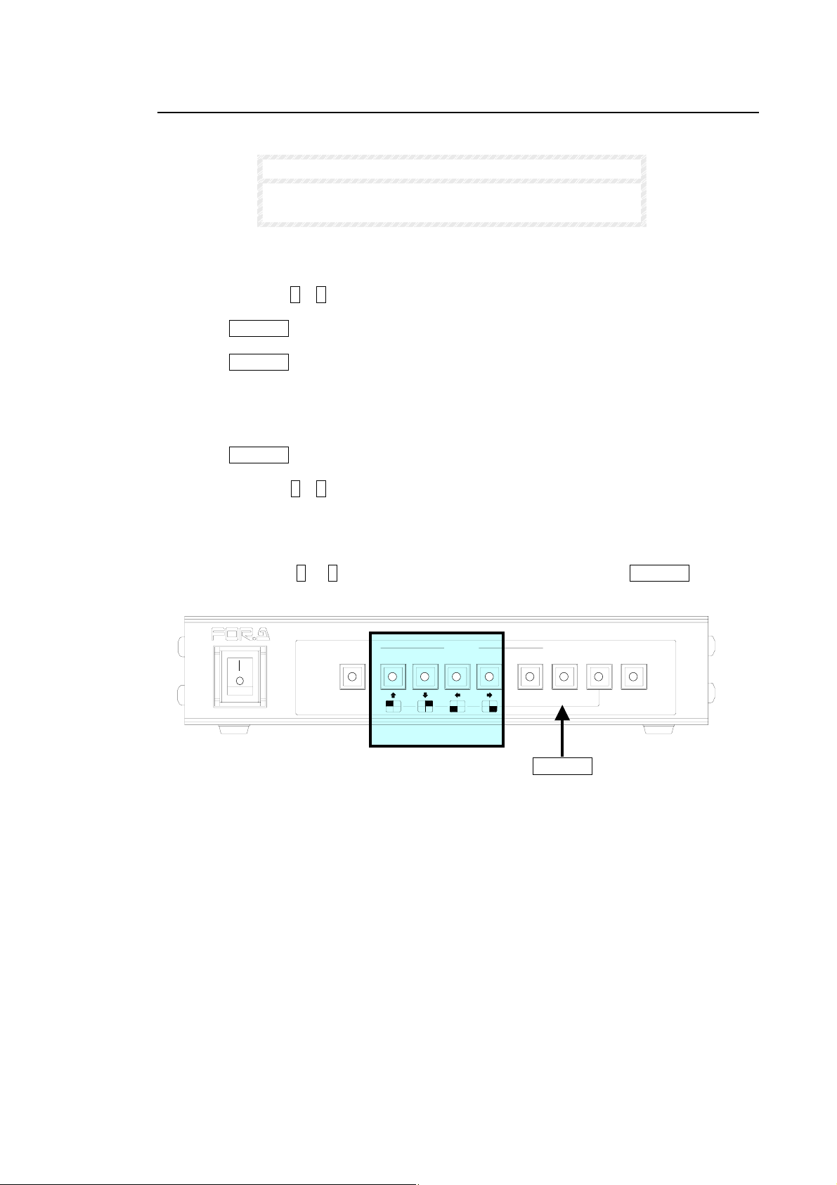
4-5-9. Freeze Select
–
Freeze screen operation is used to pause the image(s) on the desired channel(s).
NOTE
If a frozen channel loses video input, Freeze is
automatically interrupted.
To freeze a video display in full screen mode:
① Push SELECT 1 – 4 switch to select which channel you wish to freeze.
② Push FREEZE switch to lit to freeze.
③ Push FREEZE switch again to unfreeze the channel.
To freeze a video display in split and P-in-P screen mode:
① Push FREEZE switch to lit to select freeze operation.
② Push SELECT 1 – 4 switch to select which channel(s) in display you wish to freeze.
③ Selected channels will freeze and FREEZE will be monitor displayed at each frozen
channel.
④ Push SELECT 1 – 4 switch again to unfreeze that channel or FREEZE switch to
unfreeze all frozen channels.
ON
AUTO
POWER
OFF
ALARM
RESET
SELECT 1
2
SELECT
431MENUVTR
4
MULTI VIEWER MV-40F
NORMALSPLIT
ENTER *FREEZE
FREEZE
21
Page 32
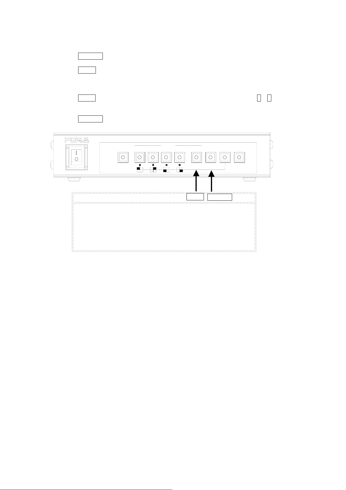
To Freeze All displayed Video in split and P-in-P screen mode:
① Push FREEZE switch to lit to select freeze operation.
② Push SPLIT switch to freeze all displayed channels.
③ All channels will freeze and FREEZE will be monitor displayed at all frozen channels.
④ Push SPLIT switch to unfreeze all displayed channels, or push SELECT 1 – 4 switch to
unfreeze each channel.
⑤ Push FREEZE switch again to return to normal operation.
POWER
ON
OFF
AUTO
ALARM
RESET
2
SELECT
431MENUVTR
MULTI VIEWER MV-40F
NORMALSPLIT
ENTER *FREEZE
NOTE
SPLIT
FREEZE
On screen display FREEZE message on frozen display channels
can be set ON / OFF by MARK parameter. See sec ‘5-5. Display’
for more information.
If video loss or alarm occurs on any channel while in FREEZE
mode, Freeze operation is automatically terminated and video loss
or alarm operation is started.
22
Page 33
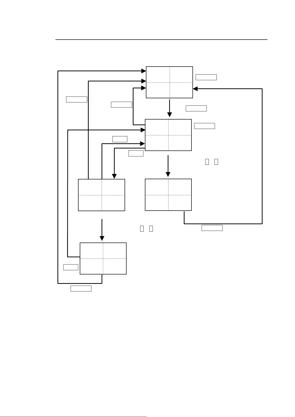
4-5-10. Freeze Mode Quick Reference Chart
t
The following quick reference chart is designed to help the operator thoroughly understand
the FREEZE functions of the MV-40F.
Push
FREEZE
switch to
unli
Push FREEZE
switch to unlit
Push SPLIT again
Push SPLIT
FREEZE
FREEZE
FREEZE FREEZE
(ALL CH FROZEN)
Push SELECT 1 – 4
T o unfreeze and refreeze CHs
Push
SPLIT
CAMERA1
FREEZE CAMERA4
FREEZE
Push FREEZE switch to unlit
Normal Display
CAMERA1
CAMERA1
Push FREEZE switch
CAMERA2
CAMERA4CAMERA3
Push SELECT 1 – 4 to freeze and
unfreeze selected channel
FREEZE
CAMERA4CAMERA3
Normal Status
FREEZE switch unlit
FREEZE switch lit
Freeze ready
Push FREEZE switch to unlit
23
Page 34
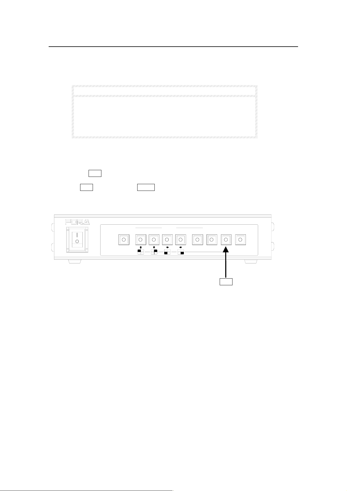
4-5-11. VTR Record / Playback
Previously recorded video material can be played back and viewed when material is input to
the VTR PB IN terminal. VTR mode is selected and playback video is output to monitor via
MONITOR OUT connector. While in VTR playback mode, played back images can be twice
zoomed. See sec ‘4-5-12. Zoom Display’ following for details.
IMPORTANT
If no signal is connected to VTR PB connector, PB NO SIGNAL is
monitor displayed while in VTR mode. In this case, check the
signal connections.
While in VTR mode no images are output from VTR REC OUT
terminal.
To View Playback Video:
① Push the VTR switch to lit indication to monitor display previously recorded video.
② Push VTR switch again or SPLIT switch to quit this function and return to live view.
ON
AUTO
2
SELECT
431MENUVTR
POWER
OFF
ALARM
RESET
MULTI VIEWER MV-40F
NORMALSPLIT
ENTER*FREEZE
VTR
24
Page 35
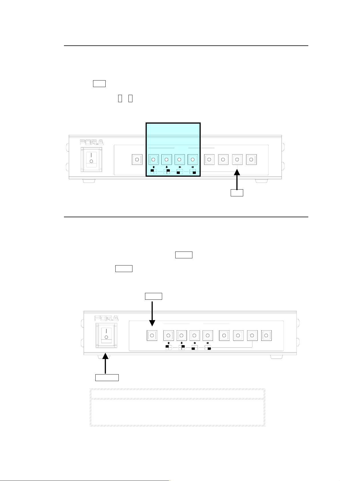
4-5-12. Zoom Display
While in VTR playback mode, the image being played back can be twice zoomed as below.
To Zoom Playback Video:
① Push VTR switch to lit,
② Push SELECT 1 – 4 switch one time to twice zoom in on that image channel.
③ Push the corresponding switch again to return channel to normal view.
SELECT 1 – 4
POWER
ON
OFF
AUTO
ALARM
RESET
2
SELECT
431MENUVTR
MULTI VIEWER MV-40F
NORMALSPLIT
ENTER*FREEZE
VTR
4-5-13. Unit Reset
MV-40F operation parameters including ’Date/Time’ settings can be returned to factory
defaults by the following procedures.
To initialize unit
① With unit power OFF, push and hold AUTO switch.
② While holding AUTO switch, turn unit power switch ON.
③ MEMORY CLEAR message will be monitor displayed and the unit should now be reset
to factory defaults.
AUTO
POWER
ON
OFF
AUTO
ALARM
RESET
2
SELECT
431MENUVTR
MULTI VIEWER MV-40F
NORMALSPLIT
ENTER *FREEZE
POWER
NOTE
See sec. ‘5-2. Time Setup’ for details on setting Date / Time after
resetting unit.
To reset unit without losing Date /Time see sec. ‘5-7. Other’
25
Page 36
4-6. External Alarm Function
A
An external alarm device can be used to input an alarm signal to the MV-40F rear panel
REMOTE/ALARM connector. Input signal will initiate alarm operation at MV-40F.
NOTES
If ALARM is set to OFF in the setup menu, alarm input will be ignored and alarm
operation will not occur. Refer to sec. ‘5-3. Alarm / Video Loss’ for details.
Alarms input while unit is in menu mode will be ignored regardless of menu
ALARM ON/OFF setting.
Alarm duration depends on which ALARM MODE is selected;
LEVEL, alarm duration continues as long as external alarm signal is input.
TRIG, alarm duration is determined by ALARM RST TIME settings.
Alarm operation of MV-40F can be cancelled so that unit returns to normal
operation by pushing ALARM REST switch if ALARM MODE is set to TRIG.
Refer to sec. '5-3. Alarm / Video Loss' for ALARM MODE details and sec. '5-2.
Time Setup' for ALARM RST TIME respectively.
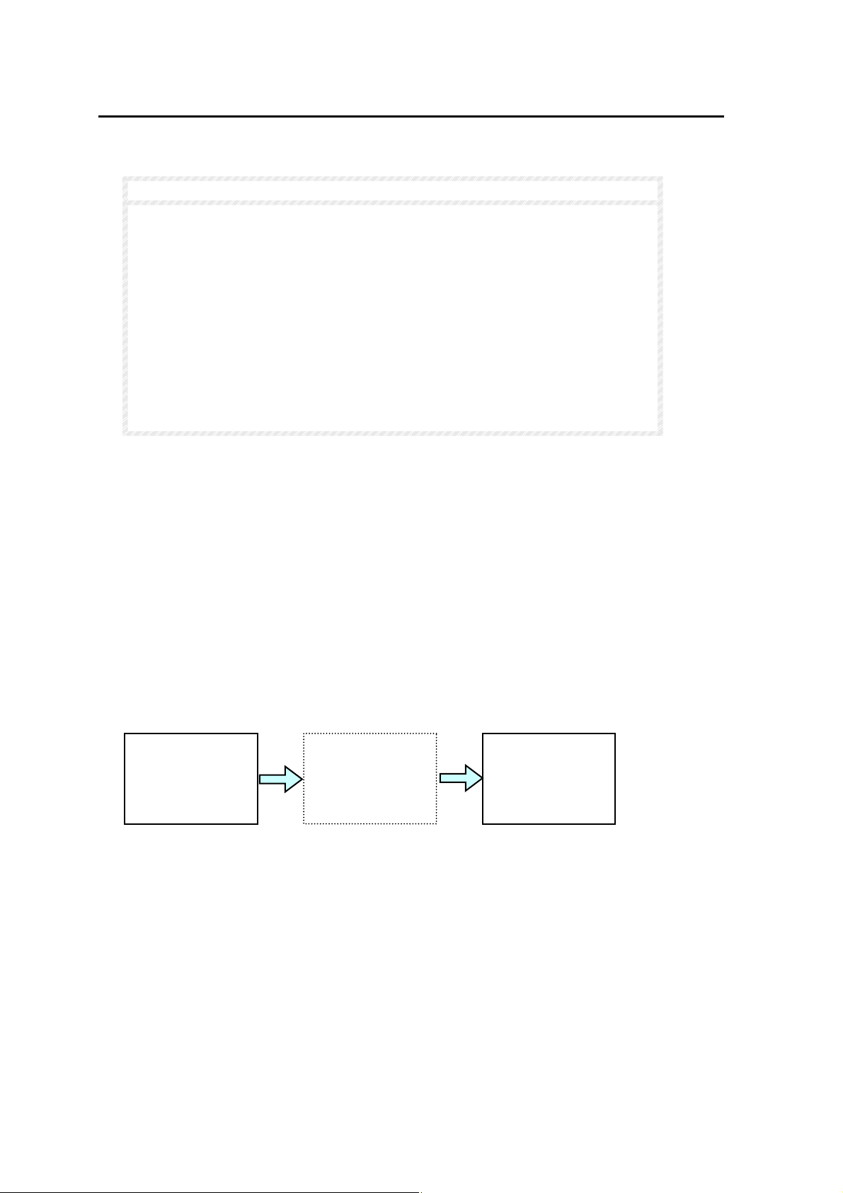
Alarm operation will be as follows based on how alarms occur:
If alarm occurs in only one channel while in full screen mode;
① Full screen display changes to alarm channel displayed in full screen. ‘ALARM’ flashes for
alarm duration if MARK superimpose set to ON. (See sec. ‘5-5. Display’ for MARK ON/OFF).
ALARM buzzer sounds for alarm duration if BUZZER set to ON. (See sec. ‘5-3. Alarm /
Video Loss’ to set BUZZER ON/OFF.)
② Alarm signal is output via the REMOTE/ALARM connector on the rear panel if ALARM OUT
is set to ON. See sec. ‘5-3. Alarm / Video Loss’ for ALARM OUT ON/OFF.
③ After alarm duration ends, alarm signal output at REMOTE/ALARM connector will go OFF,
buzzer stops and unit automatically returns to previous operation.
Alarm begins
Channel 1
Displayed
Channel 2
in alarm
LARM
If alarm occurs in 2 or more channels simultaneously while in full screen mode;
① Screen display automatically splits to Quad display. ‘ALARM’ flashes on display of all
channels in alarm if MARK superimpose set to ON. (See sec. ‘5-5. Display’ for MARK
ON/OFF). ALARM buzzer sounds for alarm duration if BUZZER set to ON. (See sec. ‘5-3.
Alarm / Video Loss’ to set BUZZER ON/OFF.)
② Alarm signal is output via the REMOTE/ALARM connector on the rear panel if ALARM OUT
is set to ON. See sec. ‘5-3. Alarm / Video Loss’ for ALARM OUT ON/OFF.
(Continued following page.)
Alarm ends
Channel 1
Displayed
26
Page 37
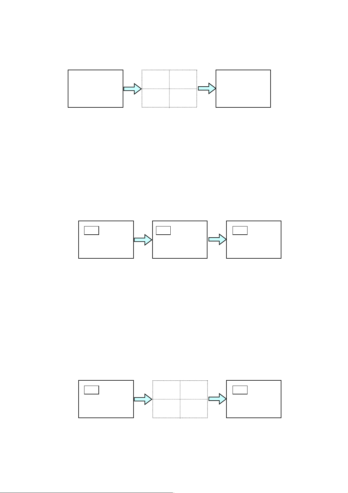
③ After alarm duration ends, alarm signal output at REMOTE/ALARM connector will go OFF,
A
A
A
A
A
A
A
buzzer stops and unit automatically returns to previous operation.
Channel 1
Displayed
Alarm begins
LARM
LARM
Alarm ends
Return to
channel 1
If alarm occurs in currently displayed channel while in P in P, split 2 or 3 mode;
① ‘ALARM’ flashes on display of all channels in alarm if MARK superimpose set to ON. (See
sec. ‘5-5. Display’ for MARK ON/OFF). ALARM buzzer sounds for alarm duration if BUZZER
set to ON. (See sec. ‘5-3. Alarm / Video Loss’ to set BUZZER ON/OFF.)
② Alarm signal is output via the REMOTE/ALARM connector on the rear panel if ALARM OUT
is set to ON. See sec. ‘5-3. Alarm / Video Loss’ for ALARM OUT ON/OFF.
③ After alarm duration ends, alarm signal output at REMOTE/ALARM connector will go OFF
and buzzer stops.
Alarm begins
larm ends
LARM
If alarm occurs in channel not currently displayed, while in P in P, split 2 or 3 mode;
① Screen display automatically splits to Quad display. ‘ALARM’ flashes on display of all
channels in alarm if MARK superimpose set to ON. (See sec. ‘5-5. Display’ for MARK
ON/OFF). ALARM buzzer sounds for alarm duration if BUZZER set to ON. (See sec. ‘5-3.
Alarm / Video Loss’ to set BUZZER ON/OFF.)
② Alarm signal is output via the REMOTE/ALARM connector on the rear panel if ALARM OUT
is set to ON. See sec. ‘5-3. Alarm / Video Loss’ for ALARM OUT ON/OFF.
③ After alarm duration ends, alarm signal output at REMOTE/ALARM connector will go OFF,
buzzer stops and unit automatically returns to previous operation.
Alarm begins
LARM
larm ends
LARM
(Continued following page.)
27
Page 38
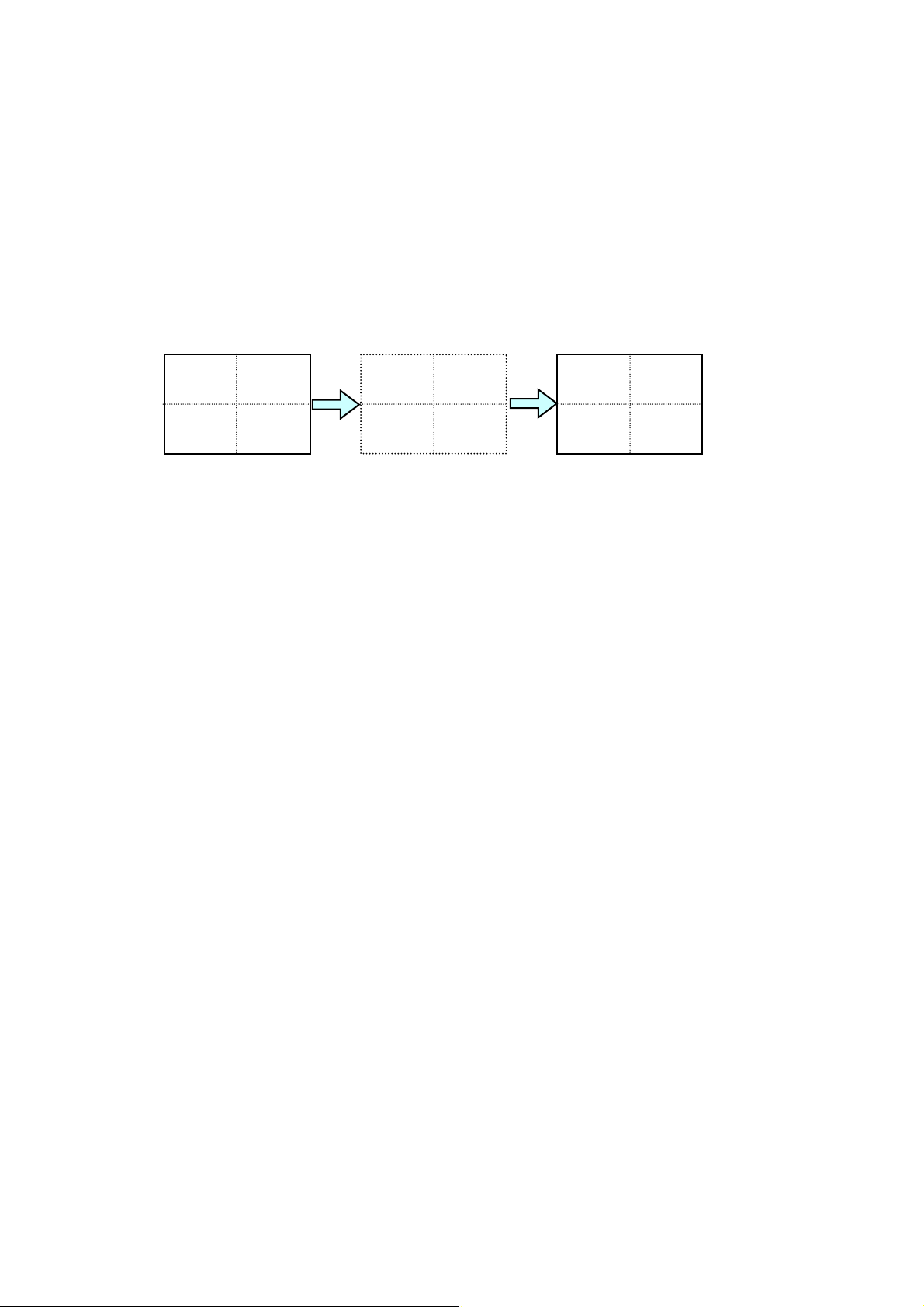
If alarm occurs while in Quad mode;
A
① ‘ALARM’ flashes on display of all channels in alarm if MARK superimpose set to ON. (See
sec. ‘5-5. Display’ for MARK ON/OFF). ALARM buzzer sounds for alarm duration if BUZZER
set to ON. (See sec. ‘5-3. Alarm / Video Loss’ to set BUZZER ON/OFF.)
② Alarm signal is output via the REMOTE/ALARM connector on the rear panel if ALARM OUT
is set to ON. See sec. ‘5-3. Alarm / Video Loss’ for ALARM OUT ON/OFF.
③ After alarm duration ends, alarm signal output at REMOTE/ALARM connector will go OFF
and buzzer stops.
Alarm begins
Alarm ends
Display
Return to
LARM
Display
28
Page 39
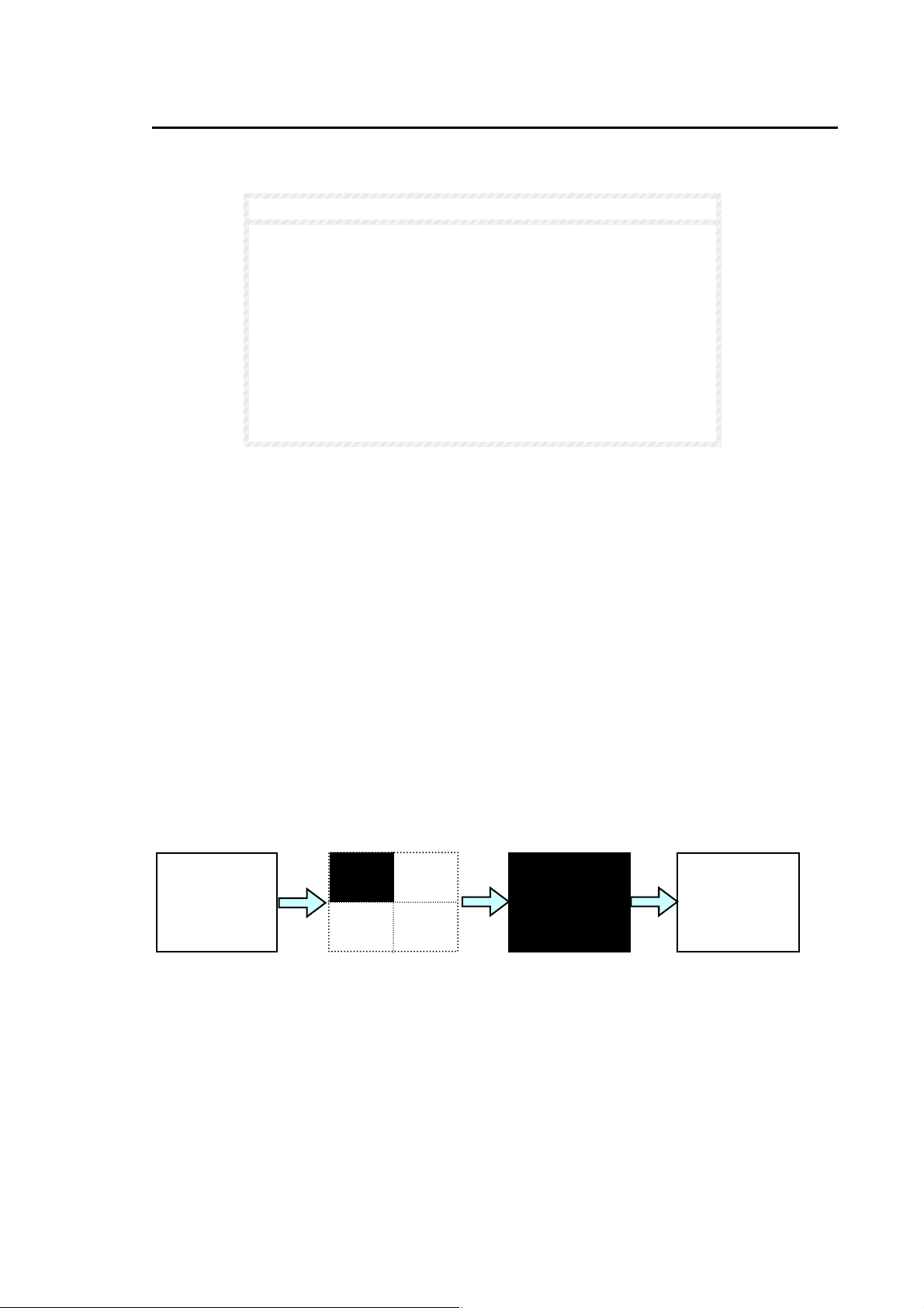
4-7. Video Loss Alarm
The MV-40F can be set to go to video loss alarm operation whenever channel input is suddenly
lost.
NOTE
If LOSS is set to OFF in the setup menu, video loss will be
ignored and video loss alarm operation will not occur. Refer to
sec. '5-3. Alarm / Video Loss’ for details.
If input video signal is not connected when power is ON, video
loss alarm operation will not occur.
Video loss while unit is in menu mode will be ignored regardless
of menu LOSS ON/OFF setting. If video signal is still lost when
exit menu mode to normal operation and if LOSS set to ON,
video loss alarm operation will be initiated.
The LOSS RST TIME timer can be reset by pushing ALARM
RESET switch in the explanation below.
Video loss alarm operation will be as follows based on how video loss alarms occur:
If video loss occurs in currently displayed channel while in full screen mode;
① Full screen display changes to Quad display. Lost signal channel will appear black and
display flashing 'LOSS' if MARK superimpose set to ON. (See sec. ‘5-5. Display’ for MARK
ON/OFF.) Buzzer sounds if BUZZER set to ON. (See sec. '5-3. Alarm / Video Loss’ for
BUZZER ON/OFF.)
② Video loss alarm signal is output via REMOTE/ALARM connector on the rear panel if LOSS
ALM OUT is set to ON. Refer to '5-3. Alarm / Video Loss’ for LOSS ALM OUT ON/OFF.
③ When LOSS RST TIME timer expires, unit will automatically return to full screen mode,
buzzer stops beep and video loss alarm signal output at REMOTE/ALARM connector goes
OFF. Full screen remains black.
④ When video signal input restored in this channel, live video is restored.
Channel 1
displayed
Video lost
LOSS
LOSS RST
time expired
Video Restored
Return to
channel 1
29
Page 40
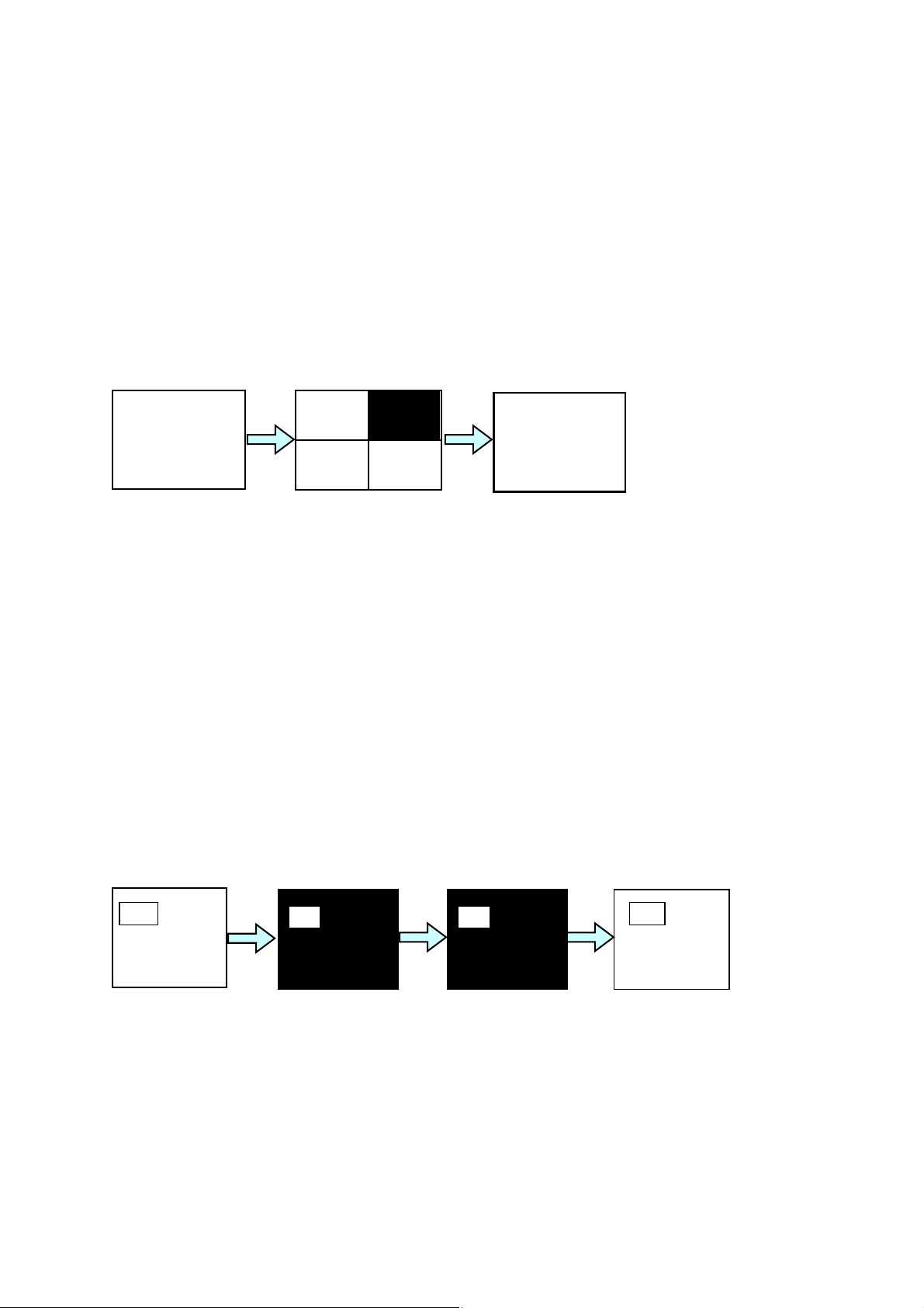
If video loss occurs in channel not currently displayed, while in full screen mode;
① Full screen display changes to Quad display. Lost signal channel will appear black and
display flashing 'LOSS' if MARK superimpose set to ON. (See sec. ‘5-5. Display’ for MARK
ON/OFF.) Buzzer sounds if BUZZER set to ON. (See sec. '5-3. Alarm / Video Loss’ for
BUZZER ON/OFF.)
② Video loss alarm signal is output via REMOTE/ALARM connector on the rear panel if LOSS
ALM OUT is set to ON. Refer to '5-3. Alarm / Video Loss’ for LOSS ALM OUT ON/OFF.
③ When LOSS RST TIME timer expires, unit will automatically return to previous full screen
mode, buzzer stops and video loss alarm signal output at REMOTE/ALARM connector goes
OFF.
Channel 1
displayed
Video lost
LOSS
LOSS RST
time expired
Return to
channel 1
If video loss occurs in currently displayed channel while in P in P, 2 or 3 split mode;
① All lost signal channels will appear black and display flashing 'LOSS' if MARK superimpose
set to ON. (See sec. ‘5-5. Display’ for MARK ON/OFF.) Buzzer sounds for alarm duration if
BUZZER is set to ON. (See sec. '5-3. Alarm / Video Loss’ for BUZZER ON/OFF.)
② Video loss alarm signal is output via REMOTE/ALARM connector on the rear panel if LOSS
ALM OUT is set to ON. Refer to '5-3. Alarm / Video Loss’ for LOSS ALM OUT ON/OFF.
③ When LOSS RST TIME timer expires, buzzer stops beep and video loss alarm signal output
at REMOTE/ALARM connector is OFF. All lost signal channels will remain black and 'LOSS'
will continue flashing on each lost signal channels.
④ When video signal input restored, live video is restored and flashing 'LOSS' is cleared.
Channel 1
displayed
Video lost
LOSS
LOSS RST
time expired
LOSS
Video Restored
Return to
channel 1
30
Page 41
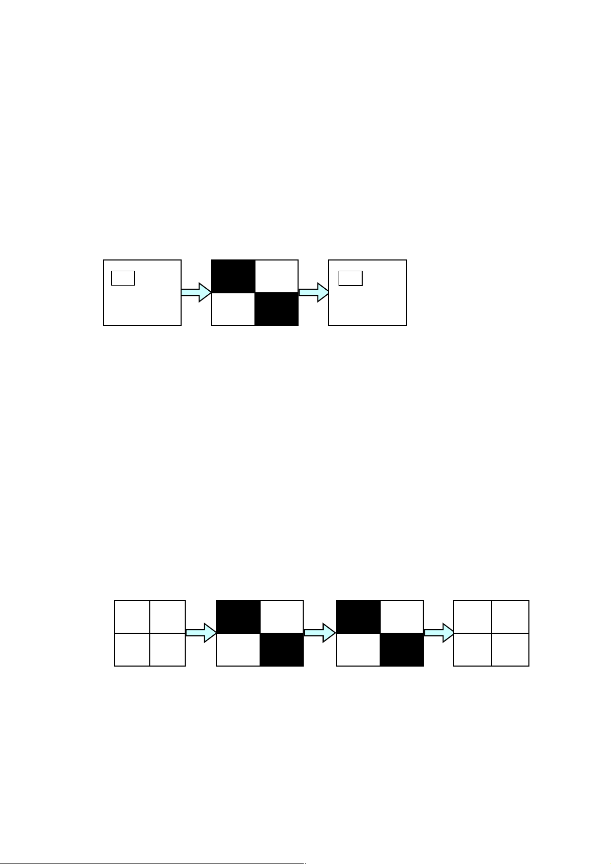
If video loss occurs in channel not currently displayed while in P in P, 2 or 3 split mode;
① Current display changes to Quad display. All lost signal channels will appear black and
display flashing 'LOSS' if MARK superimpose set to ON. (See sec. ‘5-5. Display’ for MARK
ON/OFF.) Buzzer sounds for alarm duration if BUZZER is set to ON. (See sec. '5-3. Alarm /
Video Loss’ for BUZZER ON/OFF.)
② Video loss alarm signal is output via REMOTE/ALARM connector on the rear panel if LOSS
ALM OUT is set to ON. Refer to '5-3. Alarm / Video Loss’ for LOSS ALM OUT ON/OFF.
③ When LOSS RST TIME timer expires, unit will automatically return to previous operation,
buzzer stops and video loss alarm signal output at REMOTE/ALARM connector goes OFF.
Video lost
LOSS RST
time expired
LOSS
LOSS
LOSS
LOSS
If video loss occurs while in Quad mode;
① All lost signal channels will appear black and display flashing 'LOSS' if MARK superimpose
set to ON. (See sec. ‘5-5. Display’ for MARK ON/OFF.) Buzzer beeps for alarm duration if
BUZZER is set to ON. (See sec. '5-3. Alarm / Video Loss’ for BUZZER ON/OFF.)
② Video loss alarm signal is output via the REMOTE/ALARM connector on the rear panel if
LOSS ALM OUT is set to ON. Refer to '5-3. Alarm / Video Loss’ for LOSS ALM OUT
ON/OFF.
③ When LOSS RST TIME timer expires, buzzer stops beep and video loss alarm signal output
at REMOTE/ALARM connector is OFF. All lost signal channels will remain black and 'LOSS'
will continue flashing on each lost signal channels.
④ When video signal input restored, live video is restored and flashing 'LOSS' is cleared.
Video lost
LOSS RST
time expired
Video restored
LOSS
LOSS
LOSS
LOSS
31
Page 42
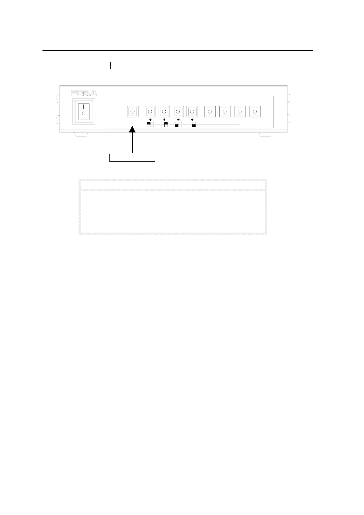
4-8. Alarm Reset
It is possible to manually stop alarm operation or to reset LOSS RST TIME timer to zero by
pushing the front panel ALARM RESET switch.
ON
AUTO
2
SELECT
431MENUVTR
POWER
OFF
ALARM
RESET
ALARM RESET
NOTE
Alarm operation can be manually stopped only when ALARM
MODE is set to TRIG.
Alarm operation can not be manually stopped when ALARM
MODE is set to LEVEL and the alarm will stop when external
alarm signal input is OFF.
MULTI VIEWER MV-40F
NORMALSPLIT
ENTER*FREEZE
32
Page 43
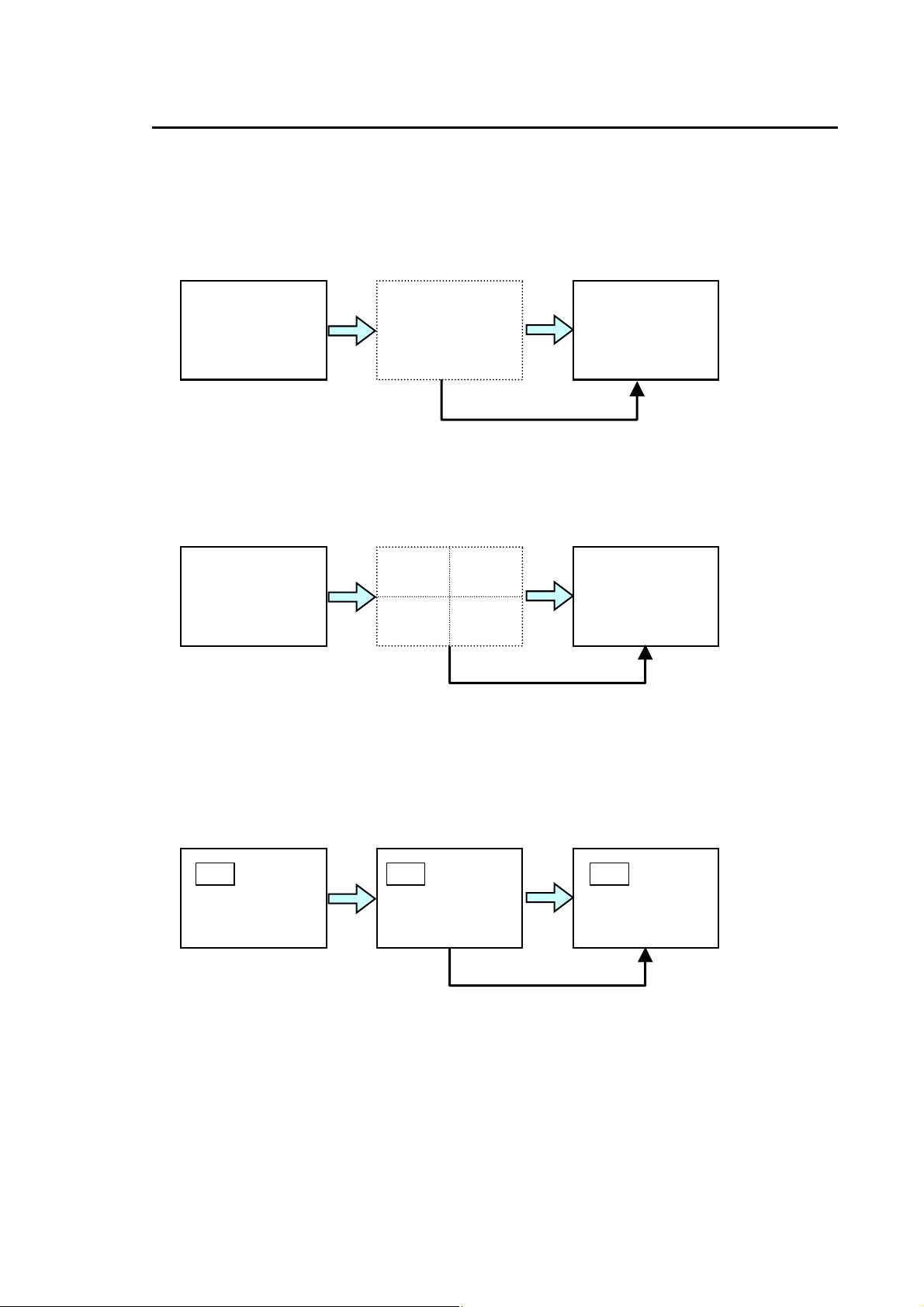
4-9. Alarm Quick Reference Chart
A
A
A
A
Alarm operations are summarized for your reference. Note that ALARM RESET switch can be
used only when ALARM MODE is set to TRIG.
If alarm occurs in only one channel while in full screen mode;
If alarm occurs in 2 or more channels simultaneously while in full screen mode;
If alarm occurs in currently displayed channel while in P in P, split 2 or 3 mode;
Channel 1
Displayed
Channel 1
Displayed
Alarm begins
Alarm begins
Alarm begins
Alarm channel
displayed
LARM
ALARM RESET switch
LARM
LARM
ALARM RESET switch
LARM
ALARM RESET switch
Alarm ends
or
Return to
channel 1
pushed
Alarm ends
or
Return to
channel 1
pushed
Alarm ends
or
pushed
(Continued following page.)
33
Page 44
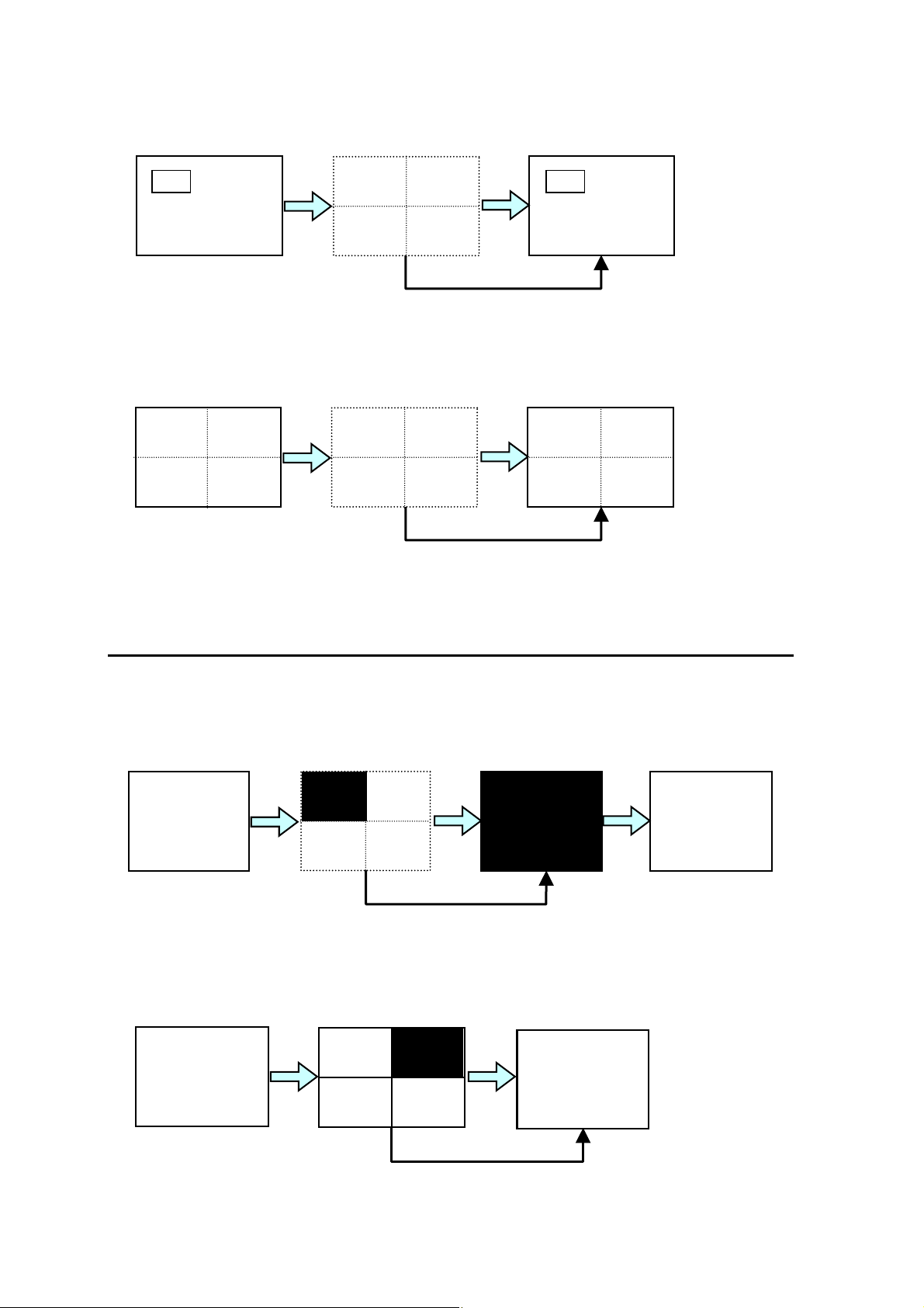
If alarm occurs in channel not currently displayed, while in P in P, split 2 or 3 mode;
A
A
A
If alarm occurs while in Quad mode;
Display
Alarm begins
LARM
Alarm begins
LARM
Alarm ends
or
LARM
ALARM RESET switch
pushed
Alarm ends
or
Return to
Display
ALARM RESET switch
pushed
4-10. Video Loss Quick Reference Chart
Video loss alarms are summarized below for your reference.
If video loss occurs in currently displayed channel while in full screen mode;
Channel 1
displayed
If video loss occurs in channel not currently displayed, while in full screen mode;
Channel 1
displayed
Video lost
LOSS
ALARM RESET switch
Video lost
LOSS RST
time expired
or
pushed
LOSS RST time expired
or
LOSS
ALARM RESET switch
pushed
Return to
channel 1
Video Restored
Return to
channel 1
34
Page 45
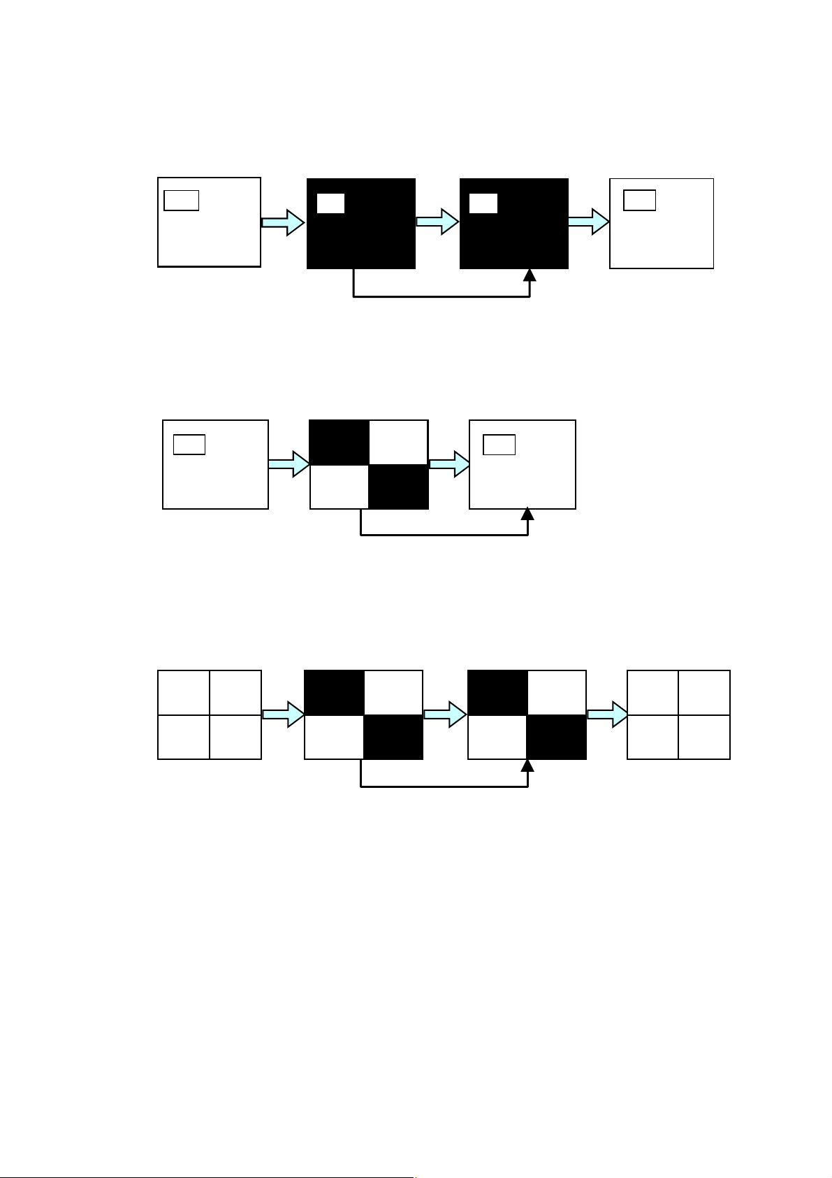
If video loss occurs in currently displayed channel while in P in P, split 2 or 3 mode;
Channel 1
displayed
Video lost
LOSS
LOSS RST
time expired
or
Video Restored
Return to
channel 1
LOSS
If video loss occurs in channel not currently displayed while in P in P, split 2 or 3 mode;
Video lost
LOSS
LOSS
ALARM RESET switch
pushed
LOSS RST
time expired
or
LOSS
LOSS
ALARM RESET switch
pushed
If video loss occurs while in Quad mode;
Video lost
LOSS
LOSS RST
time expired
or
Video restored
LOSS
LOSS
LOSS
ALARM RESET switch
pushed
35
Page 46
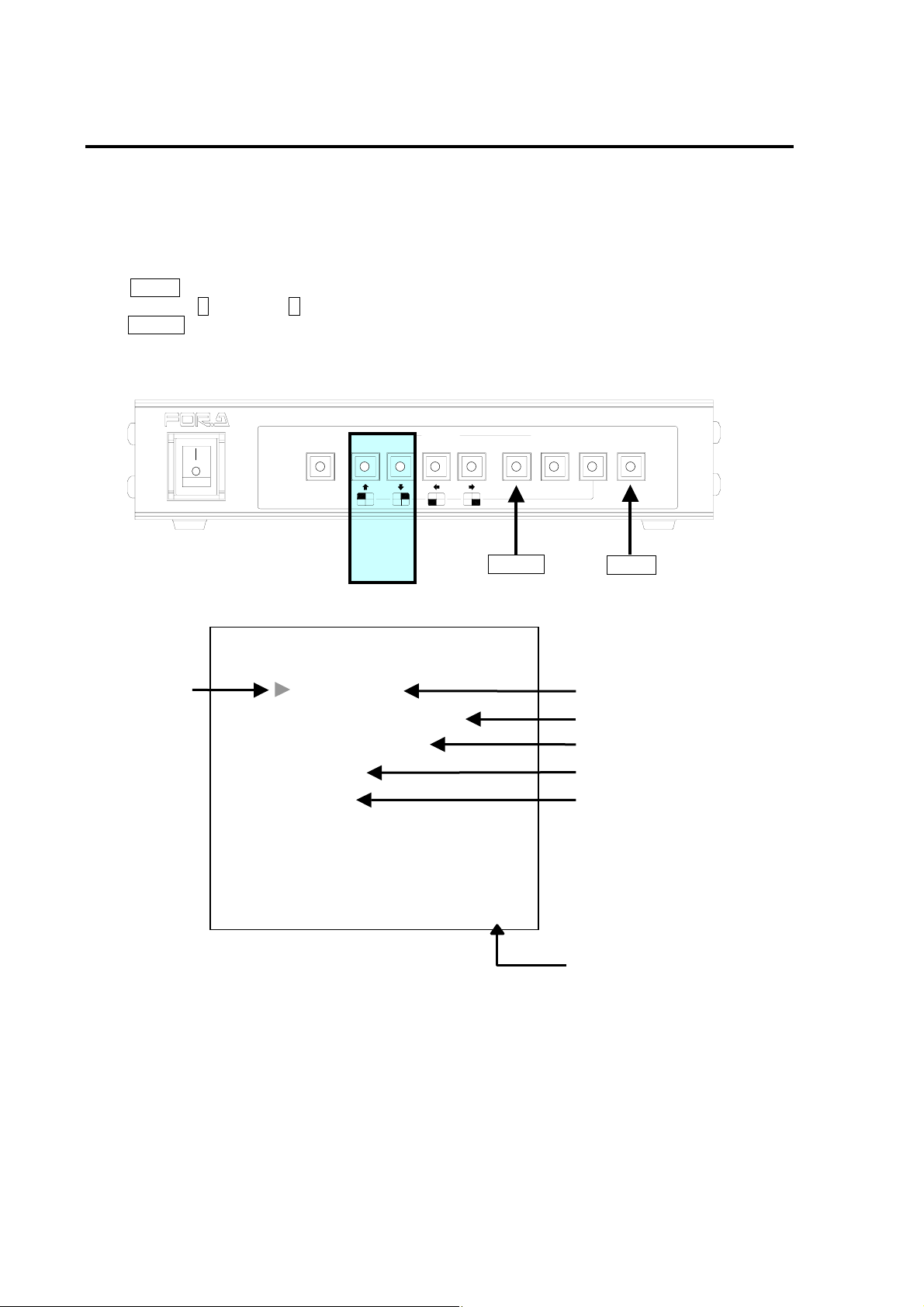
5. Main Menu
Menus can be accessed and settings made as below.
To access main menu:
Settings that can be made in the main menu are as follows;
Push MENU switch to lit indication. The main menu will be monitor displayed. Scroll cursor up or
down using up ↑ and down ↓ switch shown below. Move the cursor to the needed menu item and
push ENTER switch. The item currently selected will be visible in the menu display.
Cursor
ON
AUTO
2
OFF
POWER
ALARM
RESET
Up/
Down
MAIN MENU
TIME SETUP
ALARM/VIDEO LOSS
TITLE/POSITION
DISPLAY
OTHER
SELECT
431MENUVTR
VER XXXO
ENTER
MULTI VIEWER MV-40F
NORMALSPLIT
ENTER*FREEZE
MENU
①
②
③
④
⑤
⑥
(Continued following page.)
36
Page 47
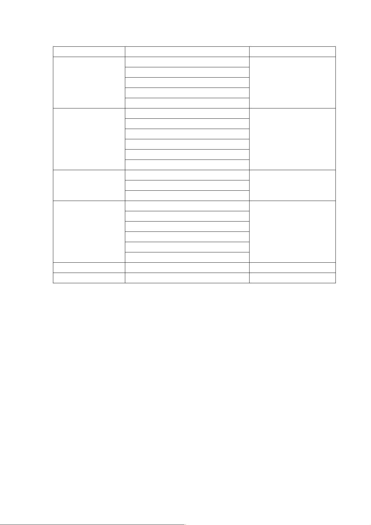
Where
Item Information Reference
Date and time setting
Automatic switching timer setting
① TIME SETUP
② ALARM/VIDEO
LOSS
③ TITLE/POSITION
④ DISPLAY
⑤ OTHER Memory clear Sec. ‘5-7. Other’
⑥ Software version Shows current software version Sec. ‘5. Main Menu’
Automatic screen switching timer setting
Alarm auto-reset timer setting
Video loss auto-reset timer setting
Alarm ON/OFF
Video Loss ON/OFF
Alarm mode Level/Trigger
Alarm output ON/OFF
Video loss output ON/OFF
Buzzer ON/OFF
Channel title setup
Title position
Date/time position
Split screen settings
REC OUT settings
Titles ON/OFF
Mark ON/OFF
Date ON/OFF
Time ON/OFF
Sec. ‘5-2. Time Setup’
Sec. ‘5-3. Alarm / Video
Loss’
Sec. ‘5-4. Title/Position’
Sec. ‘5-5. Display’
37
Page 48
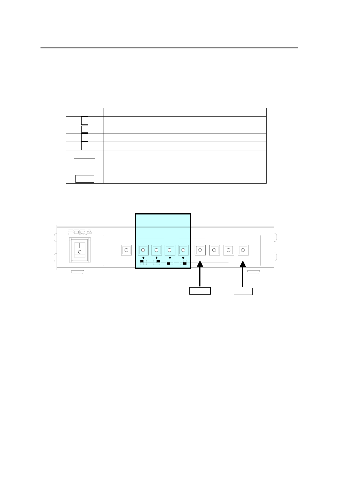
5-1. Accessing and Changing Menus
The MAIN Menu and related Sub Menus are used to make all general operational settings and
to display related settings.
Changing Menu Parameter Settings
To select and modify settings in this type of menu use the front panel controls. Standard switch
use is as listed in the following chart.
Control Result
↑ Moves cursor up.
↓
→ Moves forward through settings.
← Moves reverse through settings.
ENTER
MENU Return to previous menu / operation.
Moves cursor down.
The following actions occur:
Begin setting.
Establish input setting and/or move cursor to next setting.
Cursor Switches
POWER
ON
OFF
AUTO
ALARM
RESET
2
SELECT
MULTI VIEWER MV-40F
431MENUVTR
NORMALSPLIT
ENTER*FREEZE
ENTER
MENU
38
Page 49
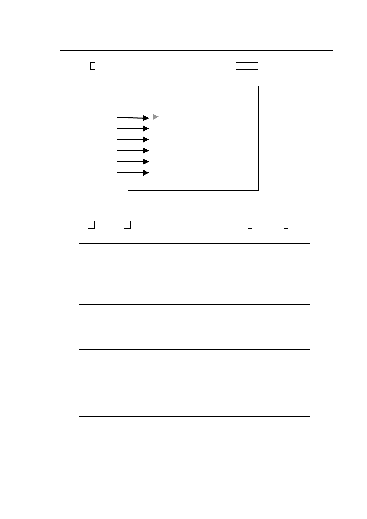
5-2. Time Setup
Settings that can be made in the Time Setup screen are as follows. From MAIN MENU use up ↑
and down ↓ switch to move cursor to TIME SETUP and press ENTER switch. The display below
should appear.
Time Setup menu settings
Use up ↑ and down ↓ switch to move cursor to desired item. Except for Date and Time adjust,
push left ← and right → switch to change selection and push up ↑ and down ↓ switch to go to
next item. Push MENU switch at any time to return to MAIN MENU.
① TIME DISPLAY
② Date and Time
③ AUTO SEQ TIME
④ FULL DISPLAY
⑤ ALARM RST TIME
⑥ LOSS RST TIME
①
②
③
④
⑤
⑥
Item Description
TIME DISPLAY 1
2002-10-10 10:10:10
AUTO SEQ TIME 01S
FULL DISPLAY OFF
ALARM RST TIME 05S
LOSS RST TIME 05S
TIME SETUP
Date can be displayed in three different ways:
1: YYYY-MM-DD
2: MM-DD-YYYY
3: DD-MM-YYYY
Factory default is 2 for NTSC and 3 for PAL. When
changing TV format, date format is automatically
reset to 2 (NTSC) or 3 (PAL).
Adjust date and time. (See next page for adjustment
procedures.) Display format is set in TIME
DISPLAY above.
Switching time of Full Screen Auto.
Setting range 1 sec. to 60 sec., 1 sec. interval.
Factory default is 1 sec.
Return timer from full screen mode to split mode
automatically when full screen mode is selected.
Setting range OFF, 1 sec. to 60 sec., 1 sec. step.
When OFF, full screen mode does not return to split
mode automatically.
Alarm reset time. Alarm status is cleared if this timer
expires only when ALARM mode is set to TRIG
(trigger). This timer is not effective when ALARM
MODE is set to LEVEL. Factory default is 5 sec.
Video loss reset time. Setting range 1 sec. to 60
sec., 1 sec. step. Factory default is 5 sec.
39
Page 50
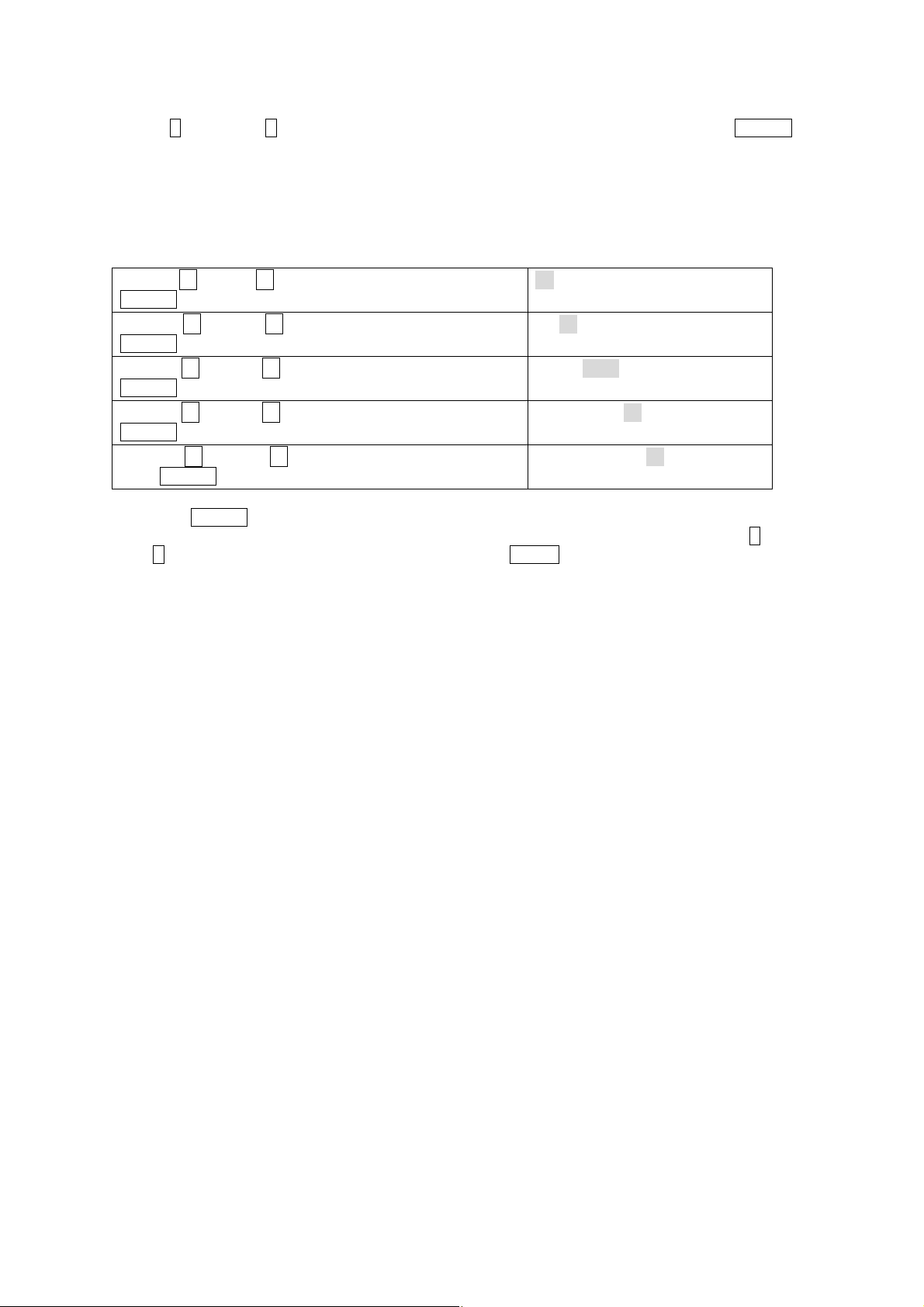
Adjusting Date and Time
Use up ↑ and down ↓ switch to move cursor to date and time display ② and push ENTE R
switch. Date and time display should appear as below with year numbers flashing. (Hatched
area shows flashing figures below.)
Date format example shown below is TIME DISPLAY default 2 (NTSC). If TIME DISPLAY is set
to default 3 (PAL), date format will appear as DD-MM-YYYY and YYYY-MM-DD if set to default
1.
Use left ← or right → switch to change month and push
ENTER switch to move to next setting day.
Use left ← or right → switch to change day and push
ENTER switch to move to next setting (year).
Use left ← or right → switch to change year and push
ENTER switch to move to next setting (hour).
Use left ← or right → switch to change hour and push
ENTER switch to move to next setting (minute).
Use left ← or right → switch to change minutes and
push ENTER switch to finish date and time setting.※
※Pushing ENTER switch makes internal clock reset to 00 second and starts the clock. Date
and Time flashing numbers stop flashing and cursor remains on Date and Time. Push up ↑ and
down ↓ switch to move cursor to other line item or push MENU switch to return to MAIN MENU.
10-29-2002 11:36:10
10-29-2002 11:36:10
10-29-2002 11:36:10
10-29-2002 11:36:10
10-29-2002 11:36:10
40
Page 51
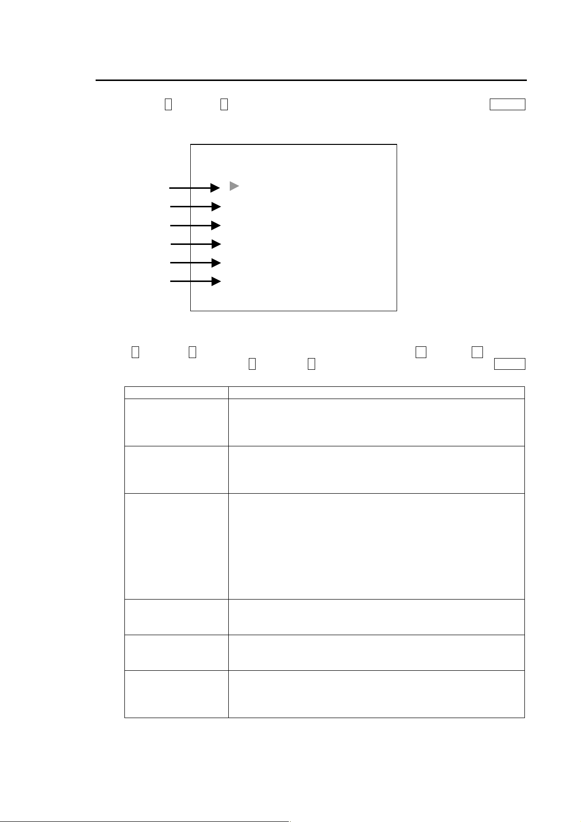
5-3. Alarm / Video Loss
Settings that can be made in the ALARM/VIDEO LOSS screen are as follows. From MAIN
MENU, use up ↑ and down ↓ switch to move cursor to ALARM/VIDEO LOSS and press ENTER
switch. The display below should appear.
Alarm/Video Loss menu settings
Use up ↑ and down ↓ switch to move cursor to desired item. Push left ← and right → switch to
change selection. Then push up ↑ and down ↓ switch again to go to next item. Push MENU
switch at any time to return to MAIN MENU.
① ALARM
② LOSS
③ ALARM MODE
④ ALARM OUT
⑤ LOSS ALM OUT
⑥ BUZZER
①
②
③
④
⑤
⑥
Item Description
LOSS ON
ALARM MODE LEVEL
ALARM OUT ON
LOSS ALM OUT ON
BUZZER ON
ALARM/VIDEO LOSS
ALARM ON
ALARM operation ON (enabled) or OFF (disabled)
If set to OFF, ALARM operation will not occur even if alarm input
signal is ON.
Factory default is ON.
Video loss alarm operation ON (enabled) or OFF disabled)
If set to OFF, video loss alarm operation will not occur even if
input video signal is lost.
Factory default is ON.
Alarm signal mode TRIG (trigger) or LEVEL (level)
TRIG: When set to trigger, alarm operation occurs when input
alarm signal becomes LOW from HIGH. Alarm status is cleared
when ALARM RST TIME timer expires.
LEVEL: When set to level, alarm operation occurs when input
alarm signal becomes LOW from HIGH. Alarm status is cleared
when input alarm signal returns to HIGH. In this case, ALARM
RST TIME timer has no effect to clear alarm status.
Factory default is LEVEL.
Alarm signal output from REMOTE/ALARM connector ON or
OFF
Factory default is ON.
Video loss alarm signal output from REMOTE/ALARM
connector ON/OFF.
Factory default is ON.
Buzzer ON or OFF when alarm or video loss alarm occurs
If set to OFF, buzzer does not sound even if alarm situation
occurs.
Factory default is ON.
41
Page 52
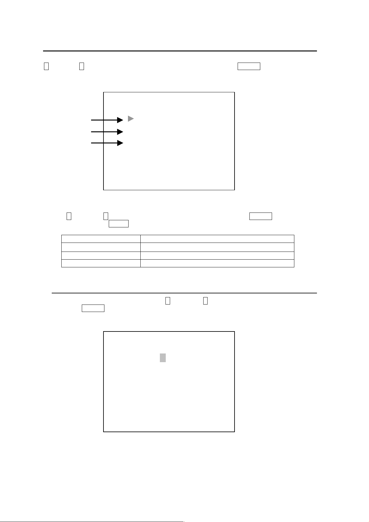
5-4. Title/Position
Settings that can be made in the Title/Position screen are as follows. From MAIN MENU, use up
↑ and down ↓ switch to move cursor to TITLE/POSITION and press ENTER switch. The display
below should appear.
Title/Position menu settings
Use up ↑ and down ↓ switch to move cursor to desired item and push ENTER switch to go to
each sub menu. Push MENU switch at any time to return to MAIN MENU.
① TITLE SET
② TITLE POSITION Title position
③ TIMER POSITION Timer position top or bottom
①
②
③
TITLE POSITION
TIMER POSITION
Item Description
TITLE/POSITION
TITLE SET
Camera titles
5-4-1. Title / Set
From TITLE/POSITION menu, use up ↑ and down ↓ switch to move cursor to TITLE/SET
and push ENTER switch. The display below should appear with flashing cursor on the first
line (CH1). (Hatched square area shows flashing cursor below.)
(Continued following page.)
CH1 CAMERA1
CH2 CAMERA2
CH3 CAMERA3
CH4 CAMERA4
TITLE/SET
42
Page 53
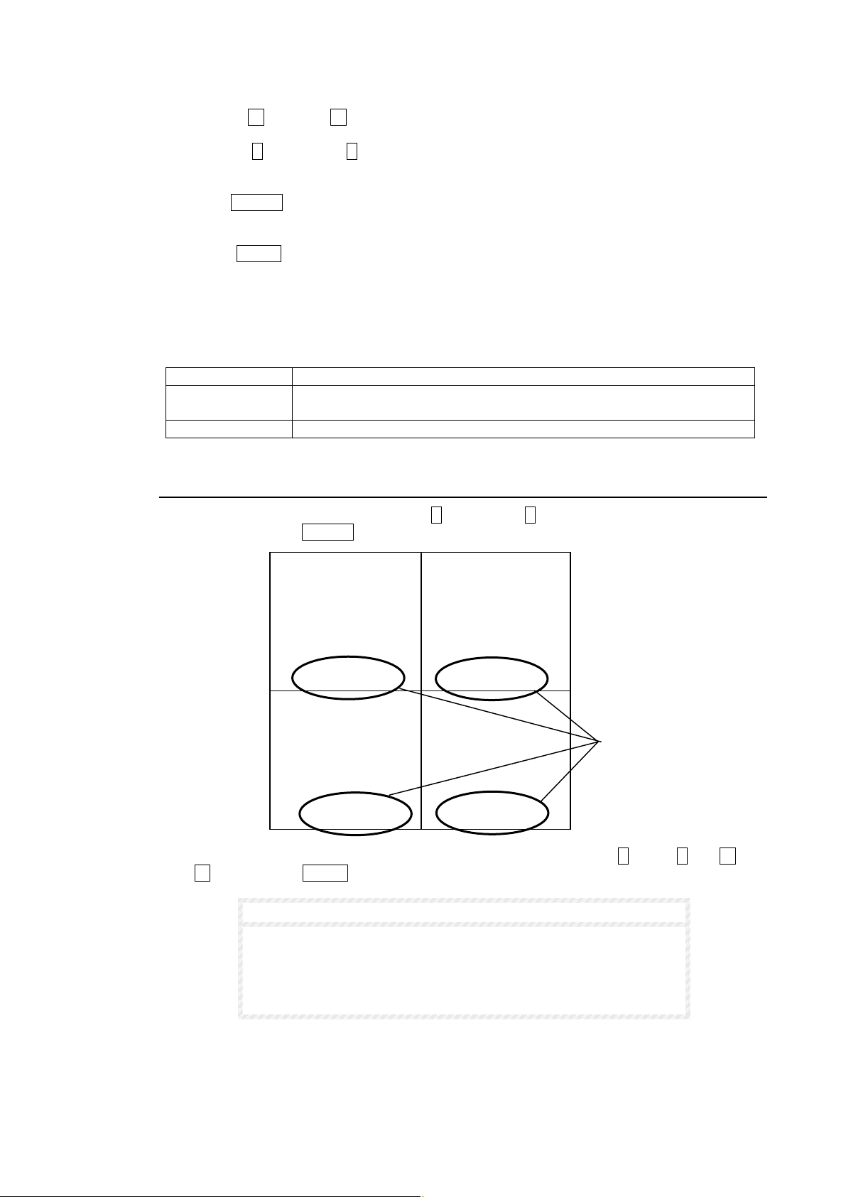
Inputting characters
A
① Use left ← and right → switch to move cursor forward and backward in a line.
② Use up ↑ and down ↓ switch to change character selection. Character selection
sequence is shown on the table below.
③ Push ENTER switch to input the currently displayed character and to move cursor to the
next line.
④ Push MENU switch at any time when finished inputting characters, to return to
TITLE/POSITION menu.
Settings list
The following letters, alphabet letters, numbers and symbols appear in this sequence. Up to 8
characters can be set in one line.
Numbers 0, 1, 2, 3, 4, 5, 6, 7, 8, 9
Alphabet Letters A, B, C, D, E, F, G, H, I, J, K, L, M, N, O, P, Q, R , S, T, U, V, W, X, Y,
Z
Symbols ?:!()+/・-space
5-4-2. Title Position
From TITLE/POSITION menu, use up ↑ and down ↓ switch to move cursor to TITLE
POSITION and push ENTER switch. The display below should appear.
Title position is applied to ALL titles and titles are moved by using up ↑, down ↓, left ← and
right → switch. Push MENU switch to go back to TITLE/POSITION menu.
Title position applies to full screen view, Quad view (4 split screen)
and the full screen during P in P view.
Title position can not be changed in 2 split, 3 split, and P in P inset
screens.
Title position cannot overlap date/time display position.
2001-09-11 09:32:10
TITLE POSITION
CAMERA1 CAMERA2
ll titles adjusted
same position.
CAMERA4 CAMERA3
IMPORTANT
43
Page 54
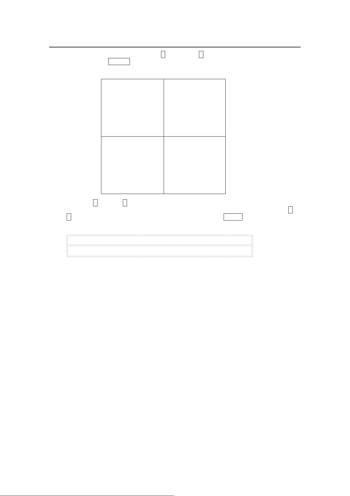
5-4-3. Timer Position
From TITLE/POSITION menu, use up ↑ and down ↓ switch to move cursor to TIMER
POSITION and push ENTER switch. The display below should appear.
Press either up ↑ or down ↓ switch to move Timer Position to either the top or the bottom of
the screen. For example, if Timer Position is at the top of the screen pressing either up ↑ or
down ↓ switch will change Timer Position to the bottom. Push MENU switch to go back to
TITLE/POSITION menu.
2002-09-11 09:32:10
TIMER POSITION
CAMERA1 CAMERA2
CAMERA4 CAMERA3
NOTE
Factory default time display position is shown above.
44
Page 55
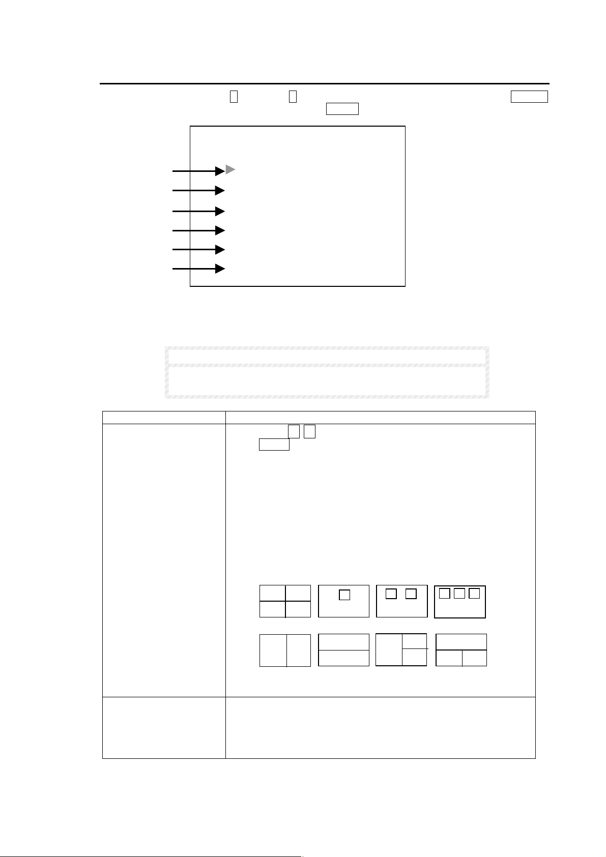
5-5. Display
From MAIN MENU, use up ↑ and down ↓ switch to move cursor to DISPLAY and push ENTER
switch. The display below should appear. Push MENU switch to return to main menu.
Settings in DISPLAY menu are shown in the table below. DISPLAY TYPE submenu has it’s own
submenu (DISPLAY SET) to adjust inset screen position of P-in-P, half sized screen view of 2
split or 3 split and channel assignment. See sec. ‘5-6. Display Set’ following for details.
①
②
③
④
⑤
⑥
DISPLAY TYPE QUAD
REC OUT QUAD
TITLE ON
MARK ON
DATE ON
TIME ON
DISPLAY
IMPORTANT
Settings made in DISPLAY set menu also affect how video is
monitor displayed and recorded.
Item Description
① DISPLAY TYPE
② REC OUT
Use cursor ← → switches to select type of screen displayed
when SPLIT switch is pushed:
QUAD: 4 split displays
PIP1: P-in-P 1 (1 full screen and 1 inset screen)
PIP2: P-in-P 2 (1 full screen and 2 inset screens)
PIP3: P-in-P 3 (1 full screen and 3 inset screens)
V2 : Vertical split 2 channels
H2 : Horizontal split 2 channels
V3 : Vertical tri-split, 1 channel left, 2 channels right
H3 : Horizontal tri-split, 1 channel top, 2 channels bottom
Sets video mode for the output from REC OUT terminal.
QUAD: Always displays video in quad screen mode.
MONITOR: Displays video in the same screen mode with the
monitor.
V2
PIP1QUAD
H2
V3
PIP3 PIP2
H3
(Continued following page.)
45
Page 56
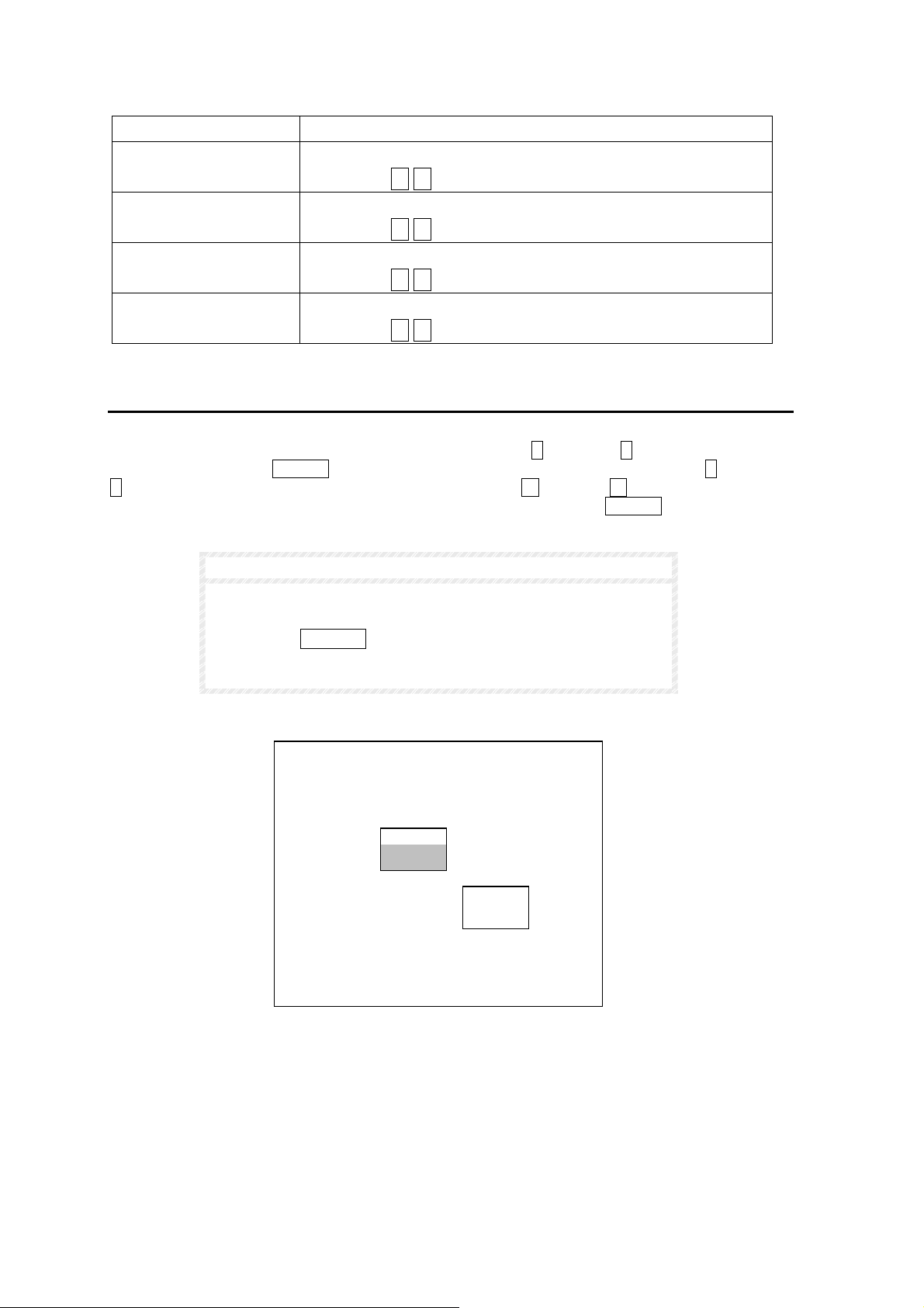
Item Description
③ TITLE
④ MARK
⑤ DATE
⑥ TIME
Sets TITLE display ON / OFF.
Use cursor ← → switches to select.
Sets ALARM, LOSS and FREEZE display ON / OFF.
Use cursor ← → switches to select.
Sets date display ON / OFF.
Use cursor ← → switches to select.
Sets time display ON / OFF.
Use cursor ← → switches to select.
5-6. Display Set
Settings can be made to adjust where P-in-P inset screen(s) are positioned or to pan / tilt the
picture in split 2 or split 3 mode. Open MAIN MENU use up ↑ and down ↓ switch to move cursor
to DISPLAY and push ENTER switch. The DISPLAY menu should appear. Use up ↑ and down
↓ switch to move cursor to DISPLAY TYPE. Then use left ← and right → switch to set DISPLAY
TYPE to one of PinP1, PinP2, PinP3, V2, H2, V3 or H3, next push ENTER switch. DISPLAY
SET menu should appear as below.
NOTE
QUAD screen display does not support this DISPLAY SET
menu.
Pushing the FREEZE switch while in DISPLAY SET with P-in-P
mode selected will enable Channel Assign function. See sec.
‘5-6-3. Channel Assign’ for details
2002-10-10 10:10:10
DISPLAY SET
CAMERA2
CAMERA3
CAMERA1
46
Page 57
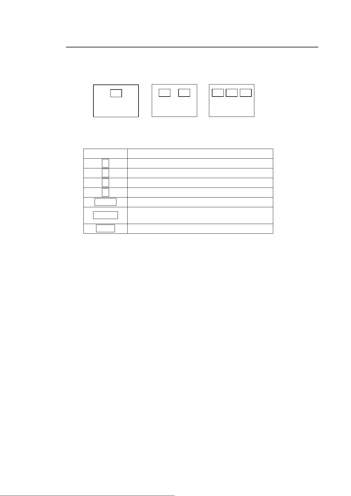
5-6-1. P-in-P mode
When in P-in-P mode, you can change the display positions of P-in-P inset screen when the
title is flashing.
Factory default P-in-P inset screen positions are as shown below.
The following table shows how to adjust P-in-P inset screen position.
P-in-P1 P-in-P2 P-in-P3
Control Result
↑ Moves selected screen up
↓ Moves selected screen down
→ Moves selected screen right
← Moves selected screen left
ENTER Changes selected screen (flashing when selected)
FREEZE
Go to CH ASSIGN menu. See sec. ‘5-6-3. Channel
Assign’.
MENU Return to DISPLAY menu
47
Page 58
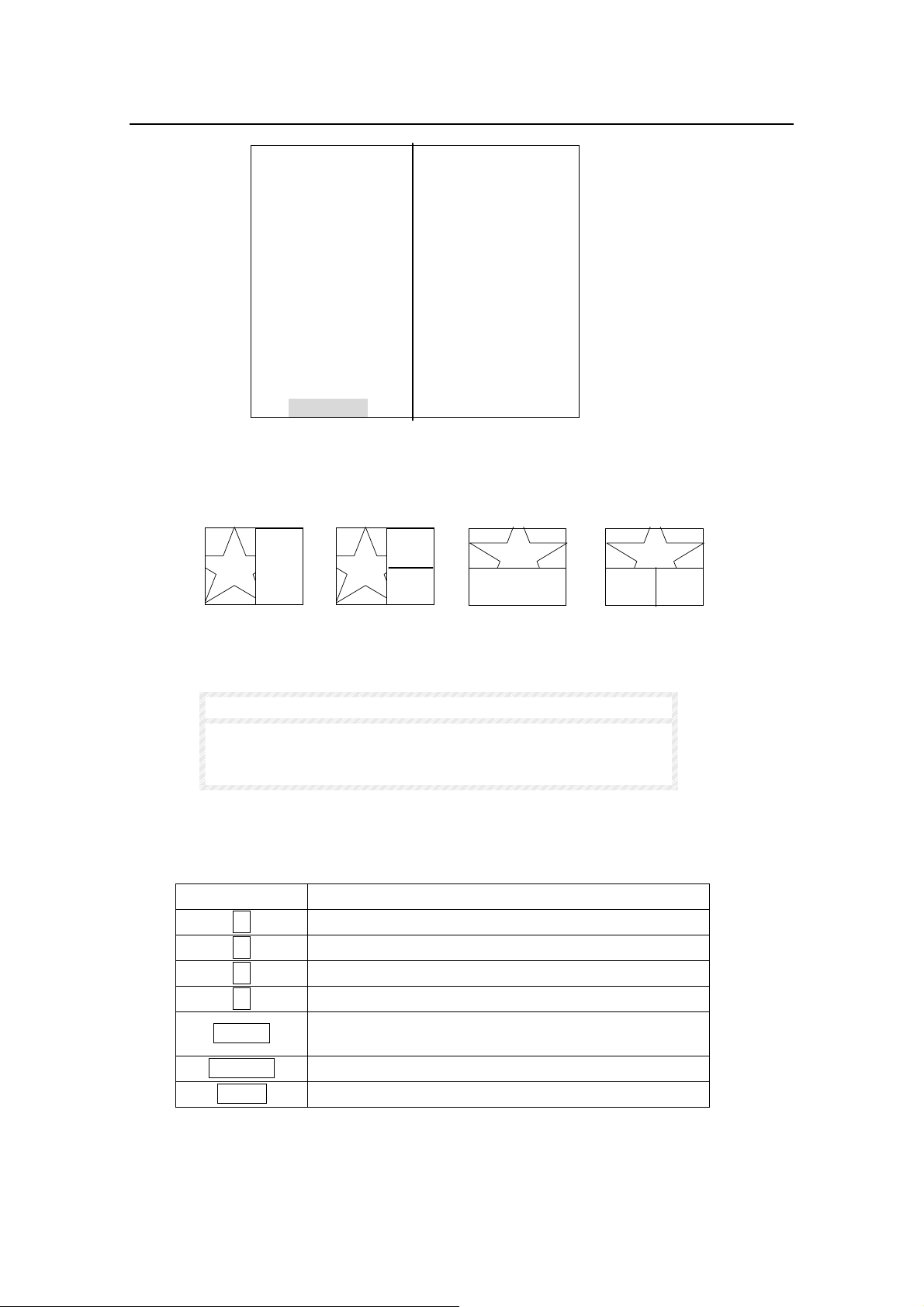
5-6-2. Split 2 or 3 Mode
When in V2, H2, V3 or H3 mode, only half sized screen view can be adjusted by tilt up/down
or pan left/right. Also when in V2 or H2 mode, only the title flashing screen view can be
adjusted. Factory default screen view settings are shown below.
V2
2002-10-10 10:10:10
DISPLAY SET
CAMERA1 CAMERA2
V3
NOTE
H2
H3
All screen views are factory default set to center view.
Reinitializing unit or memory clearing will return unit to factory
default settings from user made settings.
The table below shows how to adjust screen view.
Control Result
↑ Selected screen view is tilted up (H2 and H3)
↓ Selected screen view is tilted down (H2 and H3)
→ Selected screen view is panned right (V2 and V3)
← Selected screen view is panned left (V2 and V3)
ENTER
FREEZE CH ASSIGN (split screen channel set)
MENU Return to DISPLAY Screen
Changes selected screen (flashing when selected in
V2 and H2 only)
48
Page 59
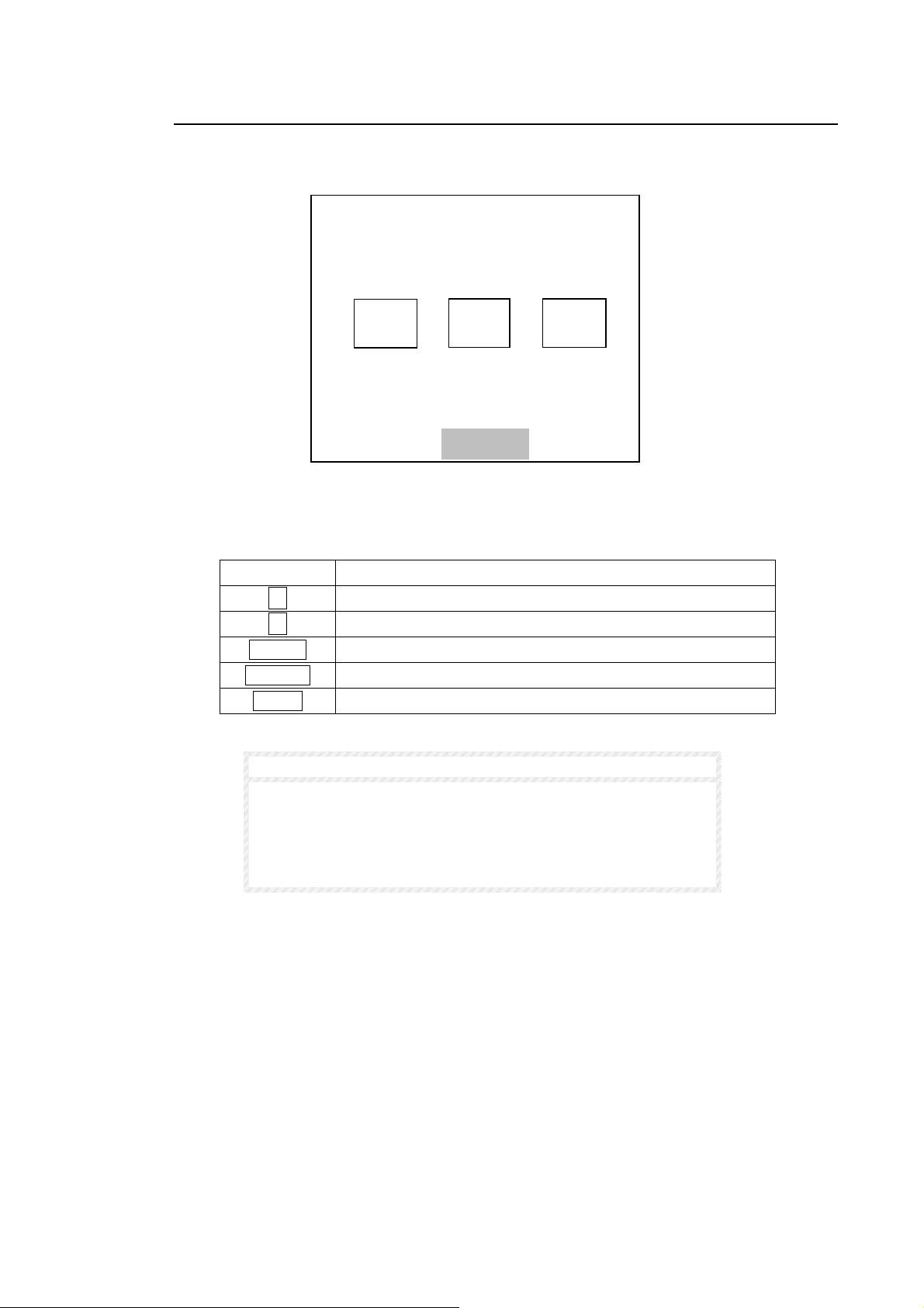
5-6-3. Channel Assign
While in DISPLAY SET menu, push FREEZE switch to go to CH ASSIGN menu shown as
below.
Factory default P-in-P3 channel assignment is shown above for example. Title flashing
screen channel can only be assigned (hatched in the figure above). The table below shows
how to assign channels.
Control Result
→ Moves channels forward through channel order
← Moves channels reverse through channel order
ENTER Change selected screen to be channel adjusted
FREEZE Return to DISPLAY SET menu
MENU Return to DISPLAY menu
2002-10-10 10:10:10
CH ASSIGN
CAMERA2
CAMERA3
CAMERA1
NOTE
CAMERA4
One channel cannot be displayed on more than one screen at a
time.
When re-assigning a channel currently displayed to another
screen, the channel currently displayed on that screen will
change to another channel as shown below.
(Continued following page.)
49
Page 60
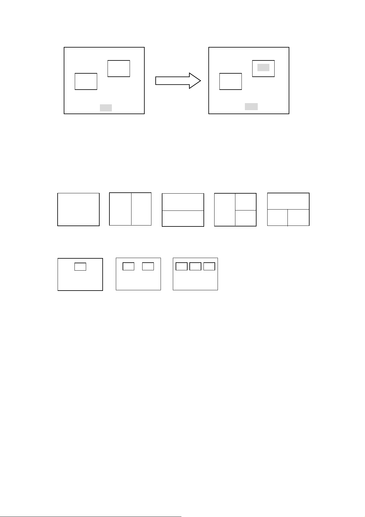
A
CH3
CH2
CH1
ssigning CH2 to full screen.
Factory default channel assignments are shown below.
CH1
CH1
CH1
CH2
CH2
Full screen
V2 V3 H3
H2
CH2
CH2 CH3
CH2
CH4CH3
CH1
PinP1 PinP2 PinP3
CH1
CH1
CH1
CH3
CH2
When CH2 is assigned to full
screen from P–in-P inset
screen, the previous full screen
channel is displayed in the
P–in-P inset screen where CH2
was previously displayed.
CH1
CH2 CH3
CH1
CH2
CH3
50
Page 61
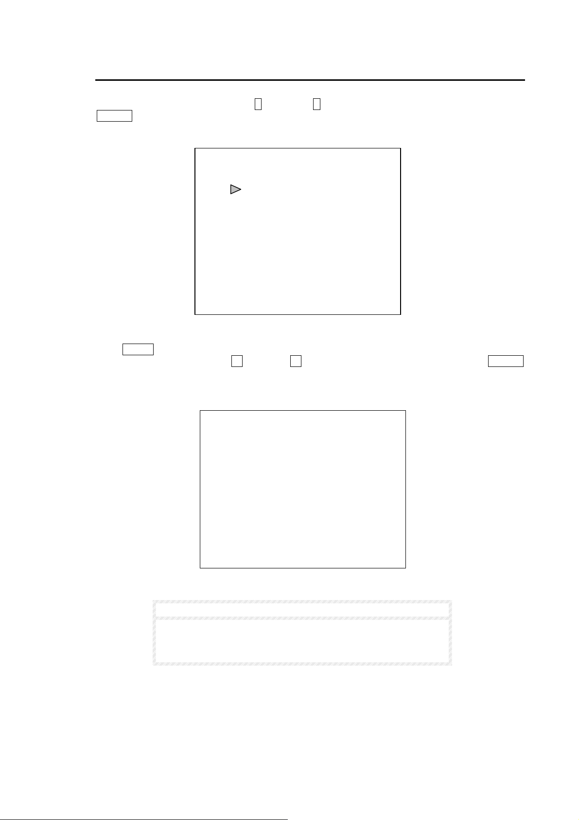
5-7. Other
Settings can be made here allows the user to reset all settings (except Date and Time) to factory
defaults. From Main Menu use up ↑ and down ↓ switch to move cursor to OTHER and press
ENTER switch. The display below should appear.
Push MENU switch to return to MAIN MENU.
To reset all settings, use left ← and right → switch to change NO to YES and push ENTER
switch. Memory clear screen shown below will be displayed. After memory clear has finished the
buzzer will sound and display will automatically return to OTHER screen.
MEM CLR NO
MEMORY CLEAR
OTHER
VER XXXO
NOTE
Memory clear requires about 7 or 8 seconds to be performed.
All user made settings except Date and Time will be reset to
factory defaults.
51
Page 62
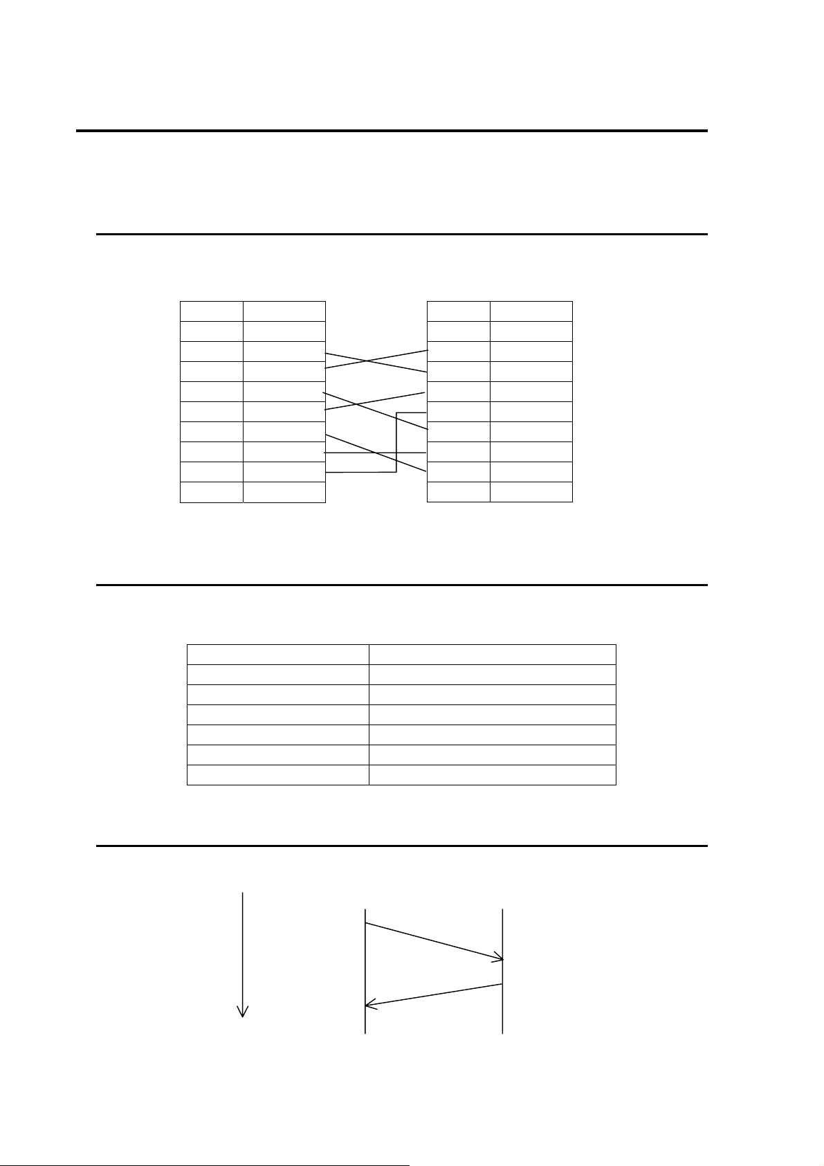
6. RS-232C Remote Control
Personal computer can be connected for RS-232C control to REMOTE/ALARM connector of
MV-40F. For REMOTE/ALARM connector pin assignment, see sec. ‘3-3. Remote / Alarm
Connector’.
6-1. Connection
Connection cable between personal computer and MV-40F is specified below.
MV-40F side
Pin No. Signal
1-17 Not Used
25-pin D-sub (male) connector
18 RXD
19 TXD
20 DTR
21 DSR
22 RTS
23 CTS
24 GND
25 GND
6-2. Communication Parameters
Personal Computer
Pin No. Signal
1 DCD
2 RXD
3
4 DTR
5 SG
6 DSR
7 RTS
8 CTS
9 Not Used
9-pin D-sub (female) connector
TXD
When controlling units via personal computer command, set communication parameters as
shown below.
Baud rate 9600
Data bits 8
Start bit 1
Stop bit 1
Parity None
X parameter (flow control) None
Synchronization Start-stop (asynchronous)
6-3 Protocol Flow
t (Time)
Control
computer
side
Control
command
Response
MV-40F side
52
Page 63

6-4. Computer Transmit
Personal computer transmits control commands using the format as shown below. It starts with
STX code (value 02H), command contents in ASCII code, and ends with ETX code (value 03H).
STX
Variable data
(Command)
ETX
02H
See sec ‘7. RS-232C Control Commands’ following for details.
03H
6-5. MV-40F Reply
① When command is properly received, ACK (06H) reply is returned.
② When command is not properly received, NAK (15H) reply is returned.
③ If command is received during alarm operations or video loss alarm operations, NAK (15H)
reply is returned.
④ If command is received while menu is accessed, NAK (15H)reply is returned.
53
Page 64
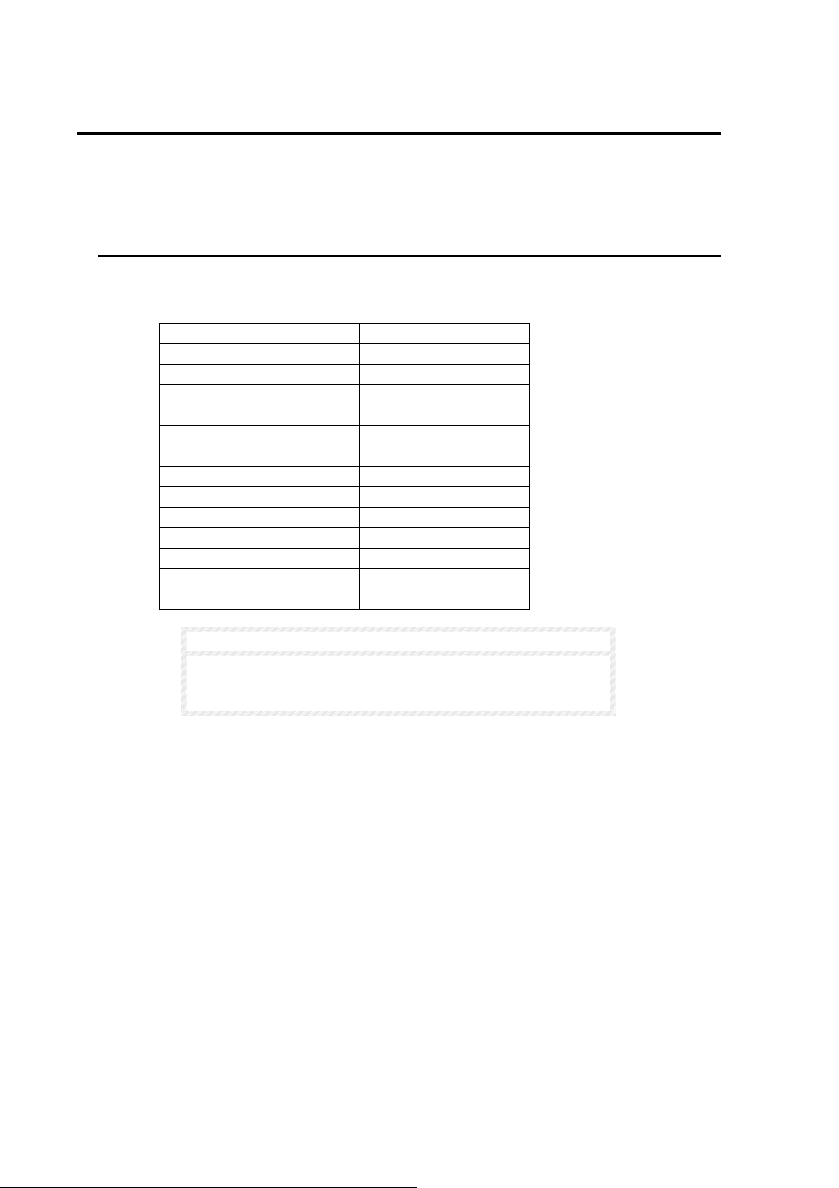
7. RS-232C Control Commands
All command contents are transmitted in ASCII code. Note that commands cannot be processed
while either in menu operation or during alarm / video loss alarm operation. If command is received
while in menu operation or during alarm / video loss alarm operation, MV-40F sends NAK (15H)
reply.
7-1. Display
Used to set display selection. Available commands are listed in the table below. Regardless of
which display selection currently set, display selection changes directly as specified by this
command.
Function Command
Full screen CH1 SF1
Full screen CH2 SF2
Full screen CH3 SF3
Full screen CH4 SF4
Full screen auto switching SAF
2 split V2 SD1
2 split H2 SD2
3 split V3 ST1
3 split H3 ST2
4 split S4
P-in-P1 SP1
P-in-P2 SP2
P-in-P3 SP3
NOTE
When one of above commands is received while in freeze or
VTR mode, MV-40F will go to normal display mode finishing
freeze or VTR mode.
54
Page 65
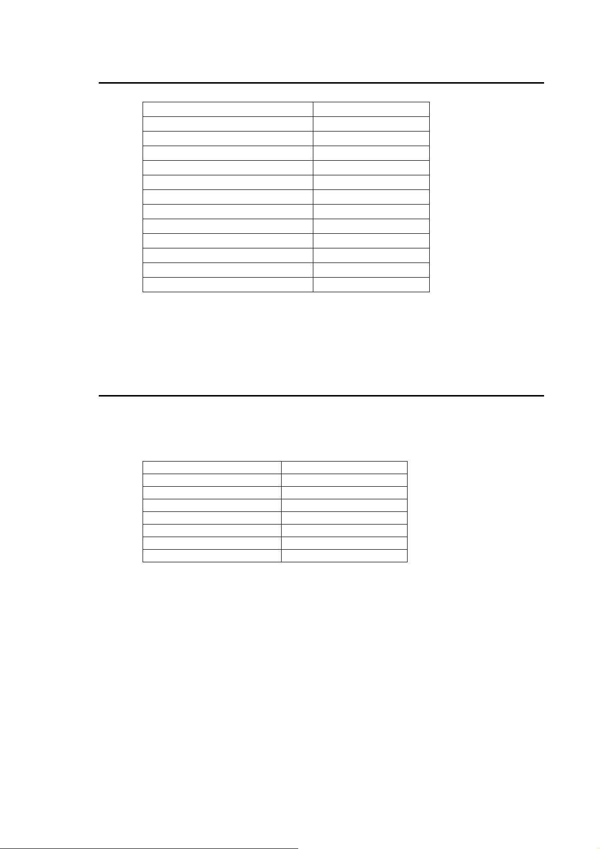
7-2. Freeze Commands
Function Command
All channels Freeze ON *1 FMO
All channels Freeze OFF *1 FMF
CH1 Freeze ON *1 FMO1
CH2 Freeze ON *1 FMO2
CH3 Freeze ON *1 FMO3
CH4 Freeze ON *1 FMO4
CH1 Freeze OFF *1 FMF1
CH2 Freeze OFF *1 FMF2
CH3 Freeze OFF *1 FMF3
CH4 Freeze OFF *1 FMF4
Full screen freeze ON *2 FMOF
Full screen freeze OFF *2 FMFF
*1 Available for split displays ( quad, P-in-P, 2-split and
3-split ).
*2 Available for full screen display.
7-3. VTR Mode Commands
VTR mode commands are listed in the table below. All commands except for VTR mode ON
command can be accepted when MV-40F is in VTR mode. When MV-40F receives VTR mode
command (other than VTR mode ON command) while it is not in VTR mode, it replies NAK
(15H).
Function Command
VTR mode ON VMO
VTR mode OFF VMF
Zoom1 VZO1
Zoom2 VZO2
Zoom3 VZO3
Zoom4 VZO4
Zoom mode OFF VZF
55
Page 66
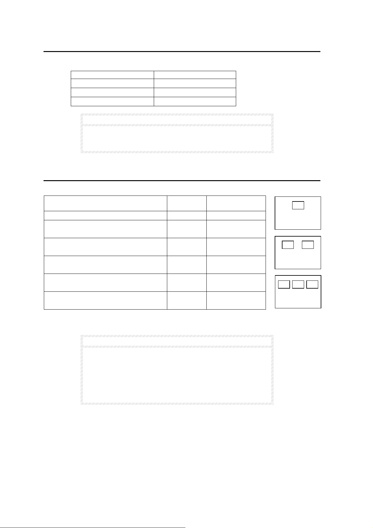
7-4. Alarm Functions
Alarm function commands are listed in the table below.
Function Command
Buzzer OFF BF
Buzzer ON BO
Alarm Reset AR
NOTE
When ALARM MODE is set to 'LEVEL' by menu setting and
Alarm Reset command ‘AR’ is received, MV-40F replies NAK
(15H).
7-5. P-in-P Inset Screen Positioning Commands
P-in-P inset screen positioning commands are listed below.
Function Command Default Position
(NTSC and PAL)
P-in-P1 inset screen positioning P1Axxyy 1804
P-in-P2 inset screen positioning,
left side inset screen default setting (A)
P-in-P2 inset screen positioning,
right side inset screen default setting (B)
P-in-P3 inset screen positioning,
left side inset screen default setting (A)
P-in-P3 inset screen positioning,
center inset screen default setting (B)
P-in-P3 inset screen positioning,
right side inset screen default setting (C)
xx: Horizontal positioning parameters; Range 01-34 (NTSC and PAL)
yy: Vertical positioning parameters; Range 01-18 (NTSC) Range 01-22 (PAL)
Each position parameter is transmitted in ASCII code.
When a parameter outside the range is received, NAK (15H) is
returned.
When a command which does not match the present screen
setup (DISPLAY TYPE) is received, NAK (15H) is returned.
When a command to overlap P-in-P screens is received, NAK
(15H) is returned.
P2Axxyy 0904
P2Bxxyy 2604
P3Axxyy 0504
P3Bxxyy 1804
P3Cxxyy 3104
NOTE
PinP1
A B
PinP2
B C
A
PinP3
56
Page 67
7-6. Split Screen 2 and 3 Positioning
Half size screen view of split 2 (V2 or H2) and split 3 (V3 or H3) can be set using commands
listed below.
Function Command
V2 view setting DM1xxxx 4646 4646
H2 view setting DM2yyyy 3131 3838
V3 view setting TM1xx 46 46
H3 view setting TM2yy 31 38
xx: Horizontal positioning parameters; Range 01-88 (NTSC) and 01-88 (PAL)
yy: Vertical positioning parameters; Range 01-60 (NTSC) Range 01-72 (PAL)
DM1xxxx
**¤¤
**: Left side half size screen view pan setting
¤¤: Right side half size screen view pan setting
DM2yyyy
**¤¤
**: Upper side half size screen view tilt setting
¤¤: Lower side half size screen view tilt setting
TM1xx
Split V3 view has only one half size screen, just one pan setting.
TM2yy
Split H3 view has only one half size screen, just one tilt setting.
NOTE
Each position parameter is transmitted in ASCII code.
When a parameter outside the range is received, NAK (15H) is
returned.
When a command which does not match the present screen
setup is received, NAK (15H) is returned.
When a command to overlap P-in-P screens is received, NAK
(15H) is returned.
Default view setting
NTSC PAL
57
Page 68
7-7. Display Status Request and Reply
Display status request command is ?G and replies are listed in the table below. MV-40F replies
with one of the messages below.
Reply Message Reply Meaning
SF1 Full screen CH1
SF2 Full screen CH2
SF3 Full screen CH3
SF4 Full screen CH4
SAF Full screen, automatic channel switching
S4 4 Split (Quad)
SP1 P-in-P1, (full screen and 1 inset screen)
SP2 P-in-P2 (full screen and 2 inset screens)
SP3 P-in-P3 (full screen and 3 inset screens)
SD1 2 Split, V2
SD2 2 Split, H2
ST1 3 Split, V3
ST2 3 Split, H3
FMx*1 Channel(s) Frozen in split display
FMOF Channel Frozen in full screen display
VMO VTR mode ON
VZO1 Zoom 1
VZO2 Zoom 2
VZO3 Zoom 3
*1 When at least one channel is frozen, MV-40F replies frozen channel(s) using FMx reply
message but does not reply which display type is currently used.
In FMx reply, x is binary expression to show frozen channel as shown below.
VZO4 Zoom 4
7
0 0 0 0
Fixed
0
CH1 Freeze
CH2 Freeze
CH3 Freeze
CH4 Freeze
7-8. Operation Mode Request and Reply
Operating Mode Request command is ?M and replies are listed in the table below. MV-40F
replies with one of the messages below.
Reply Message Reply Meaning
MA in alarm or video loss alarm operation mode
MS in menu operation mode
MD in normal operation
MF In FREEZE mode
MV in VTR mode
58
Page 69
7-9. P-in-P Inset Screen Position Request and Reply
There are 3 commands used for P-in-P inset screen position request depending on which
display type is currently being used. Commands and their replies are listed in the table below.
Request Command Function Reply Message
?P1 PinP1 inset screen position request P1xxyy
?P2 PinP2 inset screens position request P2xxyyxxyy
?P3 PinP3 inset screens position request P3xxyyxxyyxxyy
xx: Horizontal positioning parameters; Range 01-34 (NTSC and PAL)
yy: Vertical positioning parameters; Range 01-18 (NTSC) Range 01-22 (PAL)
P2xxyyxxyy
****¤¤¤¤
**** : factory defa ult left side inset screen position
¤¤¤¤ : factory default right side inset screen position
P3xxyyxxyyxxyy
****¤¤¤¤====
**** : factory defa ult left side inset screen position
¤¤¤¤ : factory default center inset screen position
==== : factory default right side inset screen position
NOTE
Command and reply are all in ASCII code notation.
When a request command which does not match the present
screen setup (DISPLAY TYPE), NAK (15H) is returned.
7-10. Split 2 or Split 3 Screen Request and Reply
In split 2 (V2 or H2) or split 3 (V3 or H3) display, only half sized screens have view setting
parameters.
There are 4 commands used for split view settings request depending on which display type is
currently being used. Commands and their replies are listed in the table below.
Request Command Function Reply Message
?D1 V2 view setting request D1xxxx
?D2 H2 view setting request D2yyyy
?T1 V3 view setting request T1xx
?T1 H3 view setting request T2yy
xx: Horizontal positioning parameters; Range 01-88 (NTSC) and 01-88 (PAL)
yy: Vertical positioning parameters; Range 01-66 (NTSC) Range 01-72 (PAL)
D1xxxx
**¤¤
**: Left side half screen view setting
¤¤: Right side half screen view setting
(Continued following page.)
59
Page 70

D2yyyy
**¤¤
**: Upper side half screen view setting
¤¤: Lower side half screen view setting
T1xx
Split V3 view has only one half size screen, just one pan setting.
T2yy
Split H3 view has only one half size screen, just one tilt setting.
NOTE
Command and reply are all in ASCII code notation. When a
request command which does not match the present screen
setup (DISPLAY TYPE), NAK (15H) is returned
60
Page 71

8. Specifications & Dimensions
8-1. Specifications
Standard
Video Inputs
VTR Input
Monitor Output
VTR OUT
Interface
Remote
Time Adjust
Alarm Input
Alarm Output
Screen Display
Types
Character Display
Camera Title
Date / Time
Warnings
ALARM
LOSS
FREEZE
Data Backup
Power
Consumption
Temperature
Humidity
Dimensions
Weight
Options
525/60 (NTSC) or 625/50 (PAL)
1.0Vp-p color or B/W (59.94Hz), 75Ω or loopthru auto terminated, 4 ea.,
BNC
VTR generated 1.0Vp-p, 75Ω, 1 ea., BNC
1.0Vp-p±0.1V, 1 ea., BNC, Full screen view or split screen view
1.0Vp-p±0.1V,1 ea., Quad or the same screen view with monitor.
Remote / RS-232C / Alarm input & output, D-sub 25 pin (female)
TTL negative logic pulse (more than 100ms width)
TTL negative logic pulse (more than 100ms width), minute signal
TTL negative logic, pulse (more than 100ms width) or level
Make break contact, max. 24VDC 100mA
Full, Quad, P-in-P 1-3 (1 full screen and between 1-3 inset screens), 2
split and 3 split vertical, 2 split and 3 split horizontal
(VTR playback allows Quad screens to be individually zoomed,
P-in-P screens can be user positioned and half size screen view of split
2 or split 3 can be user adjusted)
Alphabet, numbers, symbols, 8 characters / 1 line max, positionable
MM-DD-YYYY, H:M:S (24 hour indication) for NTSC, DD-MM-YYYY
H:M:S for PAL as factory default. Date format YYYY-MM-DD (default 1)
can also be selected.
When an Alarm occurs, ALARM is displayed on the alarm channel
screen.
When camera signal is lost, LOSS is displayed on the lost channel
screen.
When freeze is user selected, FREEZE will be displayed on all channels
currently in freeze.
Menu made settings and date/time.
Backup battery life approx. 5 years.
100VAC to 240VAC ±10%, 50/ 60Hz
Approx. 16VA (10W) at 100VAC;
Approx. 22VA (12W) at 220VAC
0°C – 40°C
30% – 90%(no condensation)
215 (W) x 44 (H) x 350 (D) mm
Approx. 1.9 kg
(1) Single Unit Rack Mount Kit
(2) Dual Unit Rack Mount Kit
61
Page 72
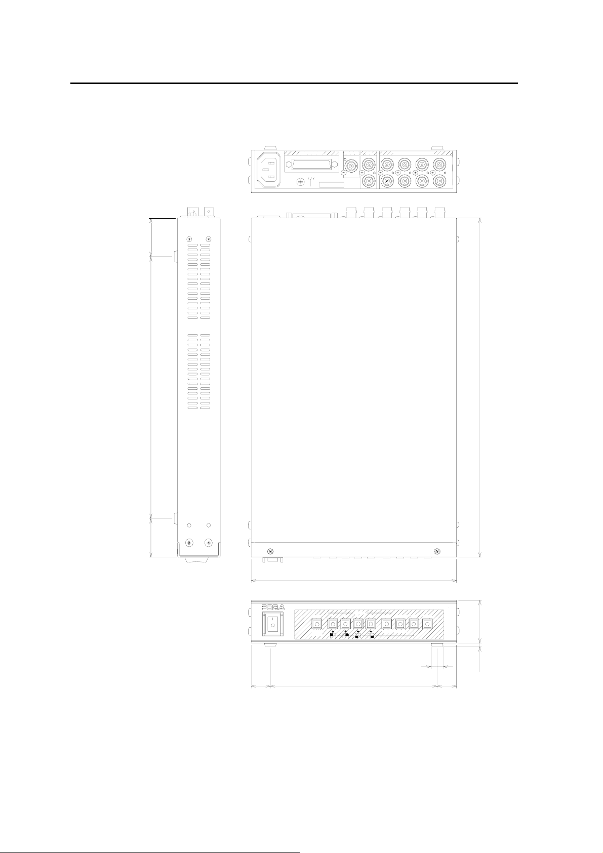
8-2. External Dimensions
(All dimensions in mm)
40
270 40
AC100-240V~ 50/60Hz IN
REMOT E/ALARMVTR MONITO R
SER.No
REC OUT
OUT
PB IN
VIDEO IN (75 AUTO TERM)
Ω
OUT
1234
IN
350
20
POWER
ON
OFF
62
AUTO
ALARM
RESET
212
SELECT
4321MENUVTR
NORMALSPLIT
ENTER*FREEZE
MV-40FMULTI VIEWER
ø12.7
172 20
3.644
Page 73
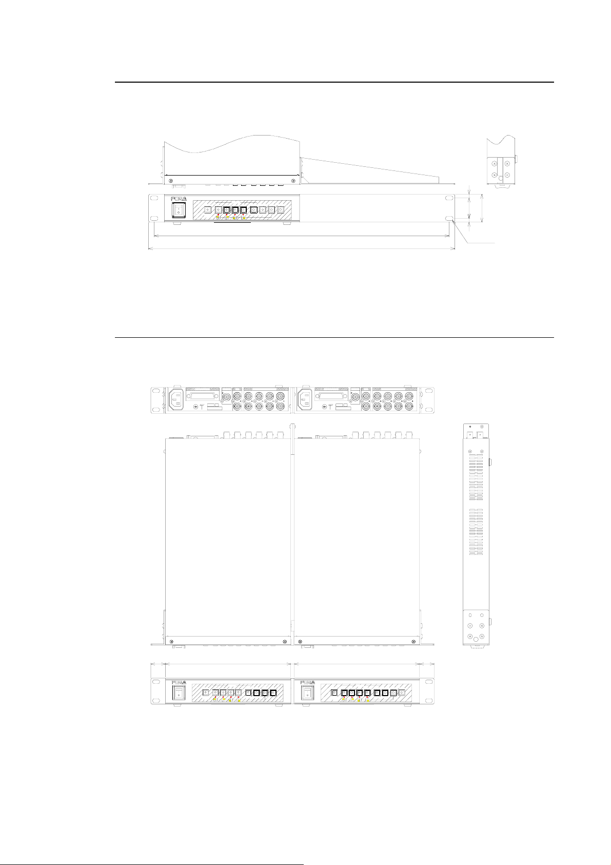
8-2-1. Single Unit Rack Mounting
(All dimensions in mm)
SPLIT NORMAL VTR MENU4321
ENTER *FREEZE
MULTI VIE WER MV-40F
SELECT
AUTO
ON
OFF
ALARM
RESET
POWER
462
480
8-2-2. Dual Unit Rack Mounting
REMOTE/ALAR M
AC100-240V~50/60Hz IN
MONITORVTR
REC OUT
OUT
PB IN4321
NTSC
J
SER.NoSER.No
VIDEO IN(75 AUTO TERM)
Ω
OUT
IN
6
32
44
6
2x2-6.4x12
(All dimensions in mm)
REMOTE/ALARM
AC100-240V~50/60Hz IN
MONIT ORVTR
REC OUT
OUT
PB IN
NTSC
J
4321
VIDEO IN(75 AUTO TERM)Ω
OUT
IN
21225
MULTI VIEWER
SELECT
1
32
AUTO
ON
ALARM
OFF
RESET
POWER
SPLIT4NORMAL
ENTER
*FREEZE
6 212
MV-40 F
MENU
VTR
25
MULTI VIE WER
SELECT
1
32
AUTO
ON
OFF
ALARM
RESET
POWER
VTR
SPLIT4NORMAL
ENTER *FREEZE
MV-40F
MENU
63
Page 74

64
Page 75

Warning
This equipment has been tested and found to comply with the limits for a
Class A digital device, pursuant to Part 15 of FCC Rules. These limits are
designed to provide reasonable protection against harmful interference
when the equipment is operated in a commercial environment. This
equipment generates, uses, and can radiate radio frequency energy and,
if not installed and used in accordance with the instruction manual, may
cause harmful interference to radio communications. Operation of this
equipment in a residential area is likely to cause harmful interference, in
which case the user will be required to correct the interference at his own
expense.
Page 76

09/29/2009 Printed in Japan
FOR-A COMPANY LIMITED
Head Office : 3-8-1 Ebisu, Shibuya-ku, Tokyo 150-0013, Japan
Overseas Division Phone: +81 (0)3-3446-3936, Fax: +81 (0)3-3446-1470
Japan Branch Offices : Osaka/Okinawa/Fukuoka/Hiroshima/Nagoya/Sendai/Sapporo
R&D/Production : Sakura Center/Sapporo Center
FOR-A America Corporate Office
11125 Knott Ave., Suite #A, Cypress, CA 90630, USA
Phone: +1 714-894-3311 Fax: +1 714-894-5399
FOR-A America East Coast Office
Two Executive Drive, Suite 670, Fort Lee Executive Park, Fort Lee NJ 07024, USA
Phone: +1 (201) 944-1120 Fax : +1 (201) 944-1132
FOR-A America Distribution & Service Center
2400 N.E. Waldo Road, Gainesville, FL 32609, USA
Phone: +1 352-371-1505 Fax: +1 352-378-5320
FOR-A Corporation of Canada
346A Queen Street West, Toronto, Ontario M5V 2A2, Canada
Phone: +1 416-977-0343 Fax: +1 416-977-0657
FOR-A Latin America & the Caribbean
5200 Blue lagoon Drive,
Suite 760, Miami, FL 33126, USA
Phone: +1-305-931-1700 Fax: +1-305-264-7890
FOR-A UK Limited
UNIT C71, Barwell Business Park, Leatherhead Road, Chessington Surrey, KT9 2NY, UK
Phone: +44 (0)20-8391-7979 Fax: +44 (0)20-8391-7978
FOR-A Italia S.r.l.
Viale Europa 50 20093, Cologno Monzese (MI), Milan, Italy
Phone: +39 02-254-3635/6 Fax: +39 02-254-0477
FOR-A Corporation of Korea
801 Dangsan Bld., 53-1 Dangsan-Dong, Youngdeungpo-Gu, Seoul 150-800, Korea
Phone: +82 (0)2-2637-0761 Fax: +82 (0)2-2637-0760
FOR-A China Limited
708B Huateng Building, No. 302, 3 District, Jinsong, Chaoyang, Beijing 100021, China
Phone: +86 (0)10-8721-6023 Fax: +86 (0)10-8721-6033
*The contents of this manual are subject to change without notice.
 Loading...