

Page 1
FA-9600
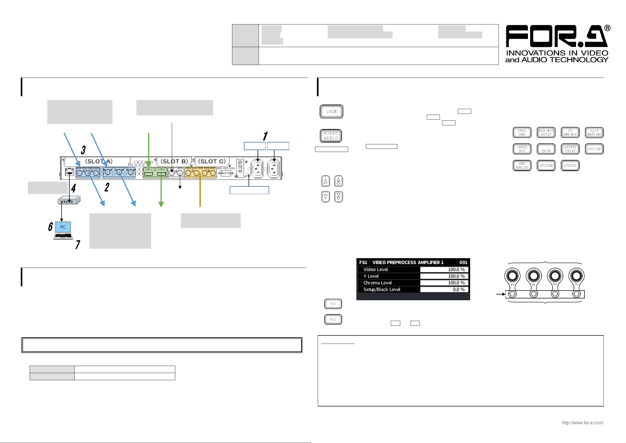
Complete connections before turning the power of the unit on.
After a setting change, do not turn the unit power off for at least 10 seconds. The setting data may otherwise not save properly.
PC IP address
192.168.0.XXX
Subnet mask
255.255.255.0
Menu buttons
Precautions
-Operate the unit only at the specified supply voltage.
-Ensure the unit is properly grounded at all times.
-Ensure the power cord and connectors are firmly connected.
-Do not access circuitry with power applied to the unit.
-Unit should not be operated or stored with the cover, panels, and/or casing removed.
-Unit should not be operated or stored in a humid, dusty, etc. environment. Doing so could result in fire or electrical shock.
-Do not allow fluids, metal fragments, or any other foreign objects to enter the unit. If foreign matter does enter the unit, turn the power
off and disconnect the power cord immediately. Remove the material or contact your authorized service representative.
-If you notice any strange smells or noises coming from the unit, turn the power off immediately, turn OFF the power switch, disconnect
the power cord, then contact your authorized service representative.
UNITY
Outlines are lit when settable.
Lit orange to indicate default values.
VIDEO/AUDIO
selection
button
AC100-240V 50/60Hz IN
12
IN2 OUT2a OUT2b
IN1 OUT1a OUT1b
IN OUT
1/2 7/85/63/4
3G/HD/SD-SDILAN 12G/6G/3G/HD/SD-SDI
GENLOCK IN
HDMI
DIGITAL AUDIO IN/OUT
B DA C
E
AC IN 1
AC IN 2
3G/HD/SD-SDI input/output.
Alternate Input and output
allocation.
Bypass relay possible
hub
Windows GUI
(FA-9600GUI)
Monitors, recorders, etc
UHD 4K input/output
possible with options.
(Single Link 12G-SDI and/or
Quad Link 3G-SDI)
GENLOCK IN with loopthrough
(Terminate at 75-ohm, if unused.)
Ground Terminal
SDI IN
HDMI IN
SDI IN
SDI OUT
SDI OUT
HDMI OUT
GENLOCK IN
DIGITAL AUDIO IN/OUT
AES I/O
Input or output selectable
LAN
100/1000BASE-T
Packing
List
FA-9600: 1 Rack mount bracket set: 1 Rubber foot: 4
AC cord: 1 set HDMI Cable Lacing Bracket: 2 sets Quick Setup Guide: 1
CD-ROM: 1 (Windows GUI installation disc, including Operation Manuals)
Option
items
FA-96PS, FA-96AES-UBL, FA-96AES-UBLC, FA-96EX3G44-R, FA-96DIN4-CBL
FA-96GPI, FA-96DB9-CBL, FA-964K, FA-96UDC, FA-96AHDR, FA-10RU
Quick Setup Guide
1. Connection
3. Front Panel Operation
Lock Button
All front panel operations are disabled when the LOCK button is lit.
To lock the front panel, press the LOCK button. The button light will turn on.
To unlock the front panel, hold down the LOCK button. The button will turn off.
Selecting a Menu
Both Video and Audio menus are assigned to some menu buttons.
The VIDEO/AUDIO button allows you to select Video or Audio menus
and lights to indicate which menu is enabled
The blue button light indicates Video menus (upper labels) are enabled,
and the orange light indicates Audio menus (bottom labels) are enabled.
Arrow buttons
Moving between menu pages: Use up/down double-arrow buttons to move between menu pages.
Moving between menu items: Use up/down single-arrow buttons to move between menu items.
The buttons are lit if available and unlit if unavailable.
Setting Parameters
Pressing a menu button displays the corresponding menu as shown below on the menu display and function button
(F1-F4) outlines will light if the buttons are available for menu setting. Lighting orange indicates that the selected
parameter is set to default.
To change parameter values, press the corresponding function buttons. (A buzzer sound will be heard if the setting
value exceeds the allowable parameter range.)
To set a parameter to its default value, press the corresponding UNITY button below F1-F4. (In such cases, repressing
the UNITY button reverts it to the previous state.)
2. Setup Procedure
The procedure is shown numbered in the above figure.
1 Apply DC power to the FA-9600 using the supplied AC cord. Secure the cord with the supplied AC cord retaining clip.
2 Connect monitors and/or recorders to the SDI OUT connectors.
3 Connect signal source devices such as video cameras and/or switchers, to the SDI IN connectors.
4 Connect a PC to be used for remote control to the FA-9600 LAN connector using a LAN cable.
5 Turn the power of the FA-9600 unit on. When the unit is powered on, all LEDs on the front panel, including Alarm indicators light.
Once startup is complete, current status will be indicated.
6 Change the PC network settings for the connection with the FA-9600.
* The FA-9600 default IP address is 192.168.0.10.
<To start up Windows GUI>
7 Install the software, FA-9600GUI.
Open the CD-ROM, and the FA-9600GUI folder. Double-click the Setup icon to start the setup wizard. Once the GUI starts up and a
GUI page opens, enter the FA-9600 IP address and click Connect to establish a connection with the FA-9600.
FS1 / FS2 Selection Buttons
“FS1” and “FS2” in front of menu titles indicate that the menu can be set independently between FS1 and FS2. Select
an FS using the FS1 and FS2 buttons.
 Loading...