

Page 1
OPERATION
MANUAL
FA-9500
Frame Synchronizer
FA-95PS
FA-95DACBL
FA-95RU
*
FA-95CO
FA-95D-D/DE-E
FA-95AIO
9th Edition – Rev. 2
SOFT Ver. 6.01 – higher
The latest FA-9500 Operation Manual can be downloaded
from FOR-A’s website:
http://www.for-a.com/products/fa9500/fa9500.html
Page 2
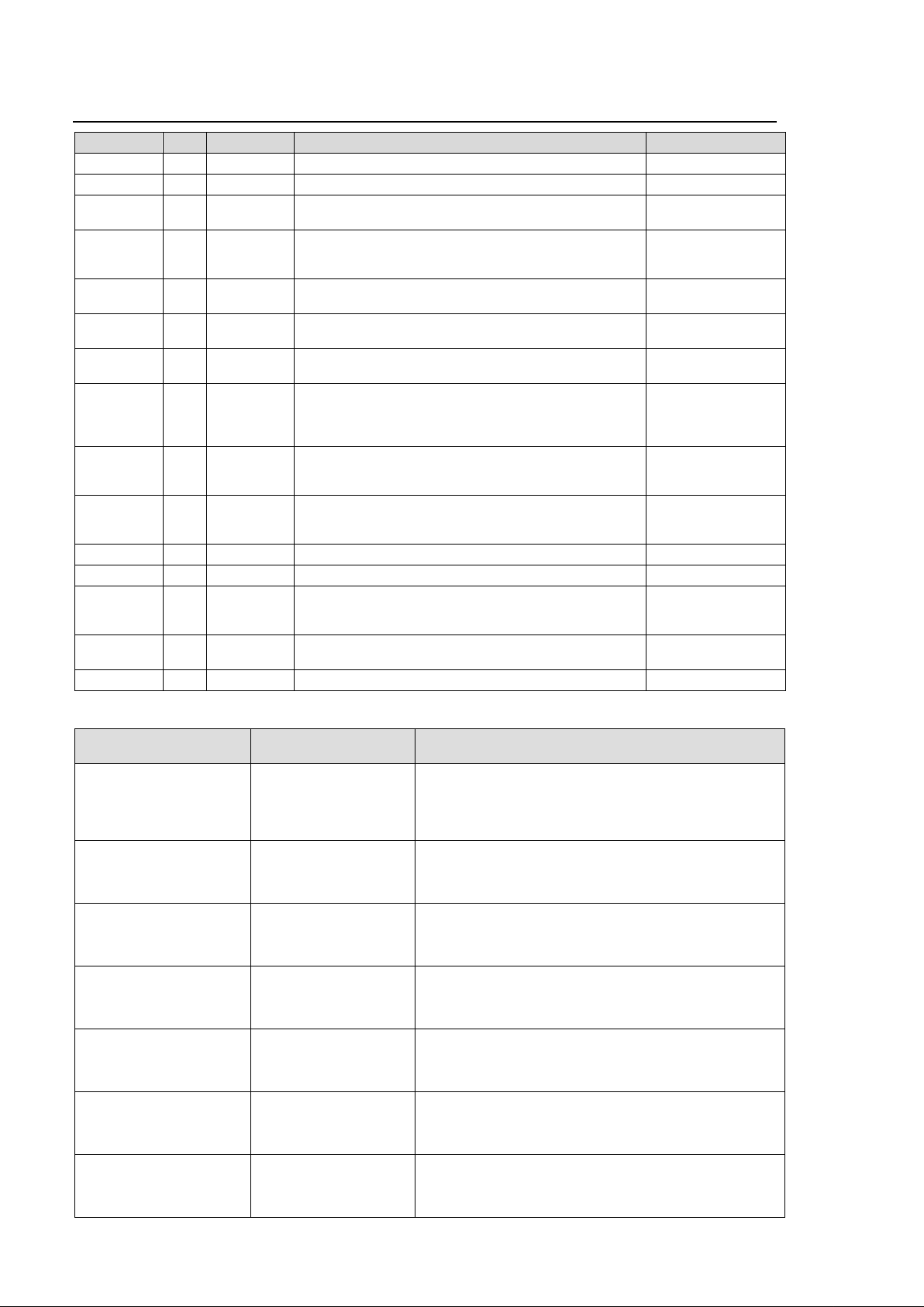
Edition Revision Histor y
Edit. Rev. Date Description Where
Preliminary - 2010/08/03 Preliminary edition (V0010)
1 2010/09/13 First edition (V0100) Throughout
1 1 2011/01/20 Added FA-95DA CB L optio n, c olor corr e ctio n
2 2011/03/23 Added 3G-SDI, Second Coverter, and Auto Video
3 2011/06/14 Added FA-95RU option.
4 2011/08/19 Added FA-95CO Option
4 1 2011/10/18 Revised AVO Scene Cut Detection frame delay, and
5 2011/11/08 Closed captioning
6 2011/12/16 Added FA-95D-D and FA-95-DE-E options.
7 2012/02/16 Added FA-95AIO option. 5-7-1, 5-8-5, 5-10-3,
7 1 2012/03/06 Deleted NTSC SETUP exceptional condition 5-15
8 2012/03/26 Added Logo feature 5-9-1
9 2012/07/06 Enhanced FA-95DE-E option.
9 1 2012/08/06 Added VITS feature description 5-10-4 through
9 2 2013/04/12 Revised specif ica tion s (optional video formats) 25-1
description. Other text amendments.
Optimizer features, and FA-95PS option. Other text
amendments.
(Issued the separate FA-95RU Operation Manual)
Added the login page and Logout button
Forced Field frame delay settings
CEA608, S334-1, CEA708 compatible
Enhanced Audio processing feature
Added PAL-M support
Added AFD support. (S2016/VI/WSS)
CONV2 modified to Up/Down/Cross conver t er.
Software Versions and Su ppor t ed Options
Version *1
FPGA1:1.36 or higher
FPGA2:1.27 or higher
FPGA3:1.01 or higher
SOFT:1.13 or higher
FPGA1: 1.40 or higher
FPGA2: 1.28 or higher
FPGA3: 1.01 or higher
SOFT : 2.00 or higher
FPGA1:1.51 or higher
FPGA2: 1.29 or higher
FPGA3: 1.01 or higher
SOFT: 2.10 or higher
FPGA1:1.55 or higher
FPGA2: 1.30 or higher
FPGA3: 1.01 or higher
SOFT: 2.22 or higher
FPGA1:1.58 or higher
FPGA2: 2.00 or higher
FPGA3:1.01 or higher
SOFT: 2.30 or higher
FPGA1: 2.08 or higher
FPGA2: 3.00 or higher
FPGA3: 1.01 or higher
SOFT: 3.00 or higher
FPGA1: 2.28 or higher
FPGA2: 4.10 or higher
FPGA3: 1.01 or higher
SOFT: 4.00 or higher
Supported
Feature/Option
FA-95PS
3G-SDI
Second Converter
Auto Video Optimizer
FA-95DACBL
FA-95RU Supports FA-95RU option.
FA-95CO Supports FA-95CO option
AVO
Scene cut detection
Closed captioning
FA-95D-D
FA-95DE-E
FA-95AIO Supports FA-95AIO option
First edition
FA-95RU ver. 1.10 or higher-compatible
Modified frame delay settings for Forced Field function.
Corrected a bug on AUTO LOAD.
FA-95RU ver. 1.20 or higher-compatible
CEA608, S334-1, CEA708 compatible
Revised menu display upon switching VIDEO/AUDIO
menus.
Supports FA-95D-D and FA-95DE-E options
Supports PAL-M
FA-95RU ver 3.00 or higher-compatible
Note
Throughout
7-1
5-7
9-1
5-5-2, 9-2-2-1,
5-10-1, 9-2-3, 9-4-1
5-10-13, 5-11, 5-12,
5-16-13 through
5-22, 9-4-1, 9-4-3,
9-7-4, 18
5-15, 5-16-13, 6-9,
9-3, 9-4, 10, 13, 19,
etc.
5-15, 5-17-2&3,
5-17-5, 7-3, 16
5-3, 5-4, 20, 21, etc.
5-10-7, 9-4-1
ii
Page 3

Version *1
FPGA1: 2.30 or higher
FPGA2: 4.10 or higher
FPGA3: 1.02 or higher
SOFT: 5.00 or higher
FPGA1:3.14 or higher
FPGA2: 5.02 or higher
FPGA3: 1.02 or higher
SOFT: 6.00 or higher
FPGA1:3.15 or higher
FPGA2: 5.10 or higher
FPGA3: 1.02 or higher
SOFT: 6.01 or higher
Supported
Feature/Option
Logo Generator Supports Logo Generator
FA-95RU ver 4.00 or higher-compatible
Added performance
features.
Added performance
features.
S2016/VI/WSS AFD support,
CONV2 Up/Down/Cross converter support, and
FA-95DE-E option enhanced encoding function.
FA-95RU ver 5.00 or higher-compatible
SD-SDI VITS output support
Note
*1 Version information can be seen as described in section 7-5 “UNIT Ver.”.
iii
Page 4
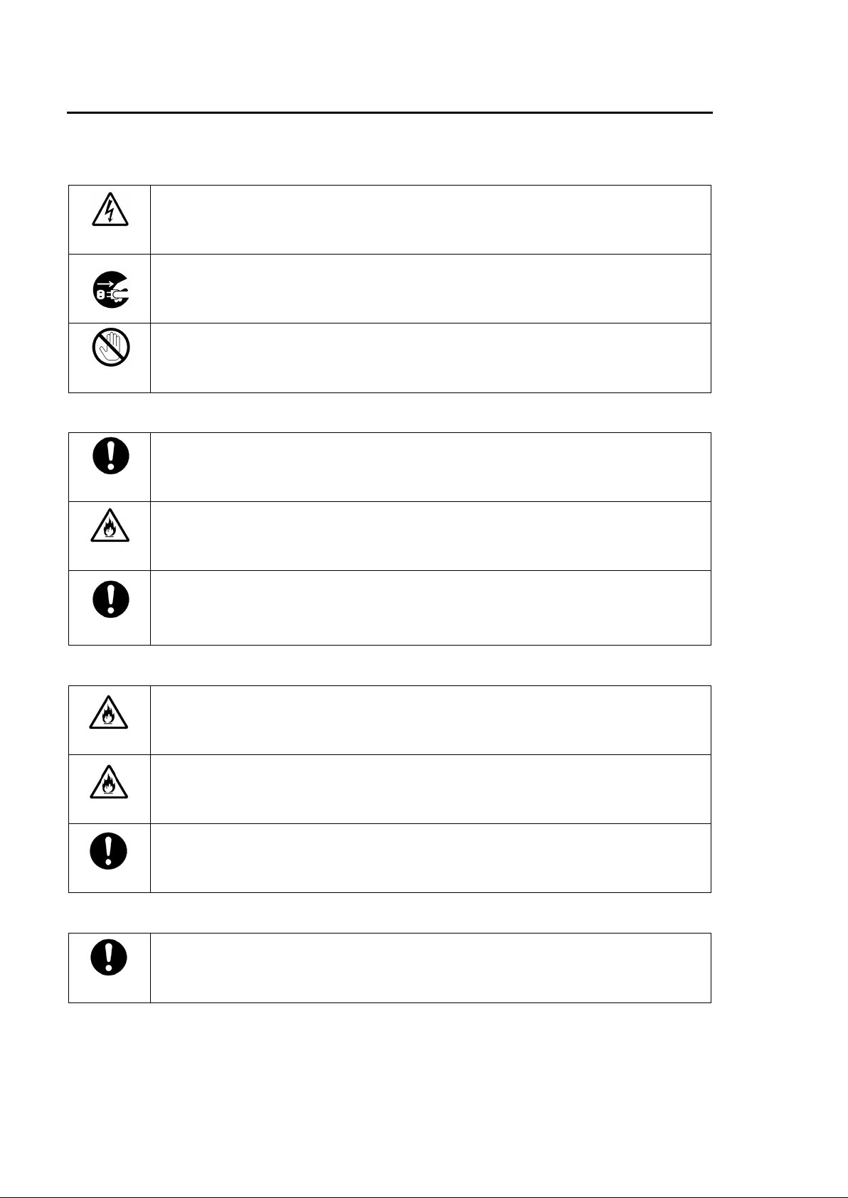
Precautions
Regularly check power cord for
nit in hazardous or potentially explosive atmospheres. Doing so
If foreign material does enter the unit, turn power off and disconnect power cord
Remove material and contact authorized service representative if
you need to transport the unit, use the original packing materials or alternate
Stop
Caution
Caution
Caution
Important Safet y Warnings
[Power]
Caution
Operate unit only on the specified supply voltage.
Disconnect power cord by connector only. Do not pull on cab le p or tion.
Do not place or drop heavy or sharp-edged objects on power cor d. A damaged cord
can cause fire or electrical shock hazards.
excessive wear or damag e to avoid possible fire / electrical hazards.
[Grounding]
Hazard
Ensure unit is properly grounded at all times to prevent electrical shock hazard.
Do not ground the unit to gas lines, units, or fixtures of an explosive or dangerous
nature.
Ensure power cord is firmly plugged into AC outlet.
[Operation]
Hazard
Hazard
Do not operate u
could result in fire, explosion, or other dangerous results.
Do not a llow liquids, metal pieces, or other foreig n materia ls to enter the u nit. Doing
so could result in fire, othe r hazards, or unit malfunction.
immediately.
damage has occurred.
[Transportation]
Handle with care to avoid shocks in transit. Shocks may cause malfunction. When
adequate packing.
iv
Page 5
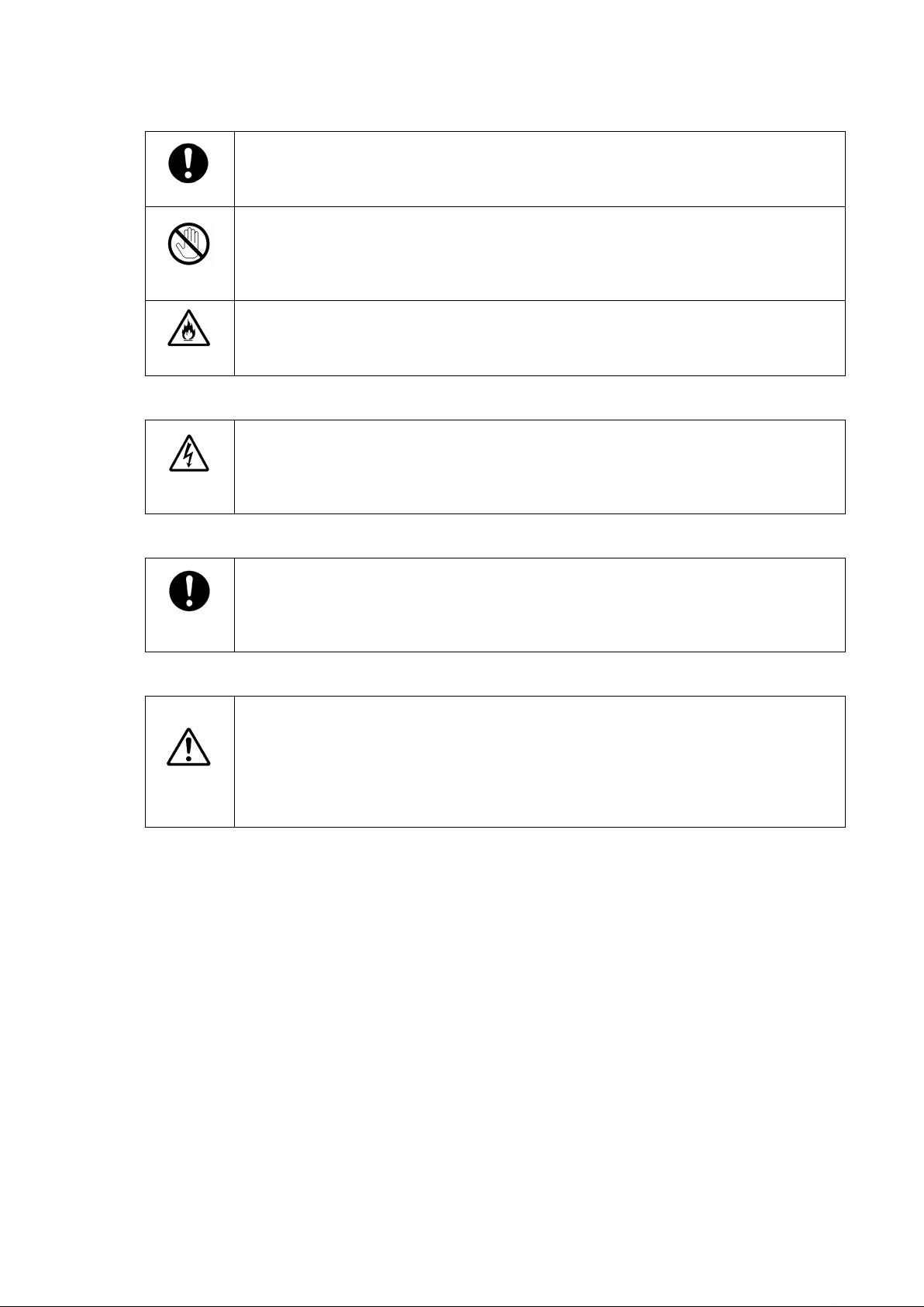
[Circuitry Access]
after power is disconnected. Capacitors associated with the power supply are
If abnormal smells or noises are noticed coming from the unit, turn power off
which parts are consumables and when they should be replaced, refer to the
l. Since the service life of the
consumables varies greatly depending on the environment in which they are used,
Caution
Stop
Hazard
Do not remov e covers, panels, cas ing, or acc ess circuitry with power applied t o the
unit! Turn power off and di sconn ect pow er cord pr ior to r emova l. Internal servicing /
adjustment of unit should only be performed by qualified personnel.
Do not touch any parts / circuitry with a high heat factor.
Capacitors can retain enough electric charge to cause mild to serious shock, even
especially hazardous. Avoid contact with any capacitor s.
Unit sho uld not be operated or stored with c over, pa nels, and / or casing r emov ed.
Operating unit with circuitry exposed could result in electric shock / fire hazards or
unit malfunction.
[Potential Hazards]
Caution
immediately and disconnect power cord to avoid potentially haz ardous conditions. If
problems similar to above occur, contact authorized service representative before
attempting to again operat e unit.
[Rack Mount Brackets, Ground Te rm inal, and Rubber Feet]
To rack mount or ground the unit, or to install rubber feet, do not use screws or
materials other than th ose supplied. Otherwise, it may cause d amage to the internal
circuits or components of t he unit. If you remove the rubber feet attached on the unit,
do not reinsert the screws securing the rubber feet.
[Consumables]
Caution
The consumables used in unit must be replaced periodically. For further details on
specifications at the end of the Operation Manua
they should be replaced at an early date. For details on r eplacing the consumables,
contact your dealer.
v
Page 6
Upon Receipt
Unpacking
FA-9500 units and their accessories are fully inspected and adjusted prior to shipment.
Operation can be performed immediately upon completing all required connections and
operational settings.
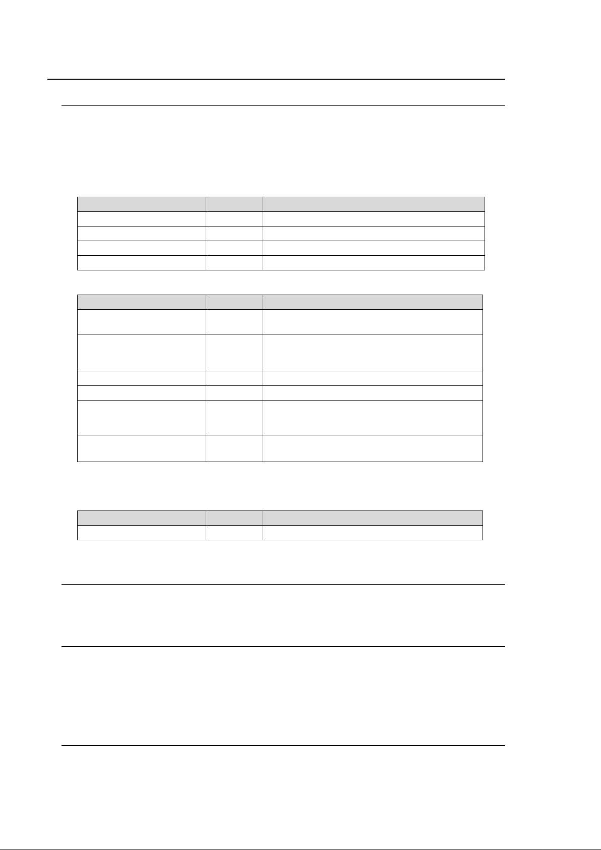
Check your received ite m s against the packing lists below.
FA-9500
ITEM QTY REMARKS
FA-9500 1
AC Cord 1 set (Incl. ladder strap/r et a in in g c lip assembly)
Rack Mount Brackets 1 set EIA standard type (Including 4 screws.)
Operation Manual 1
Option
ITEM QTY REMARKS
FA-95PS 1 set
FA-95DACBL 1
FA-95RU 1 Remote Control Unit
FA-95D-D * 1 Dolby E/Digital decoder
FA-95DE-E 1
FA-95AIO * 1
* FA-95D-D, and FA-95AIO options (any co mbination other than 2 of the same option) can be
installed into option slots A and/or B.
Software Option
ITEM QTY REMARKS
FA-95CO 1 Changeover
Check
Redundant power supply unit (with AC cord and
AC cord retaining clip)
Digital audio expansion cable (to expand digital
audio I/O up to 8 inputs and 8 outputs.)
Normally installed in slot B.
Dolby E encoder
FA-95D-D option required for FA-95DE-E
installation.
Analog component I/O expansion card
(with dedicated connection cable: PC-3307)
Check to ensure no damage has occurred during shipment. If damage has occurred, or items
are missing, inform your supplier immediately.
Trademark
Microsoft and Windows are either registered trade marks or trademarks of Micros oft Corporation
in the United States and/o r ot her count r ies.
Pentium and Intel Core ar e t r ademarks of Intel Corporation in the U.S. and/or other countries.
Firefox is a registered trademark of the Mozilla Foundation.
All other trademarks are trademarks or registered trademar ks of their respective owners.
Rack Mounting
FA-9500/RPS can b e mounted to EIA standard rac k unit s. When rack mounting a unit , r em ove
the rubber feet and use the accessory rack mount brac kets (r ack ears).
vi
Page 7
Installing the AC Cord Retaining Clip
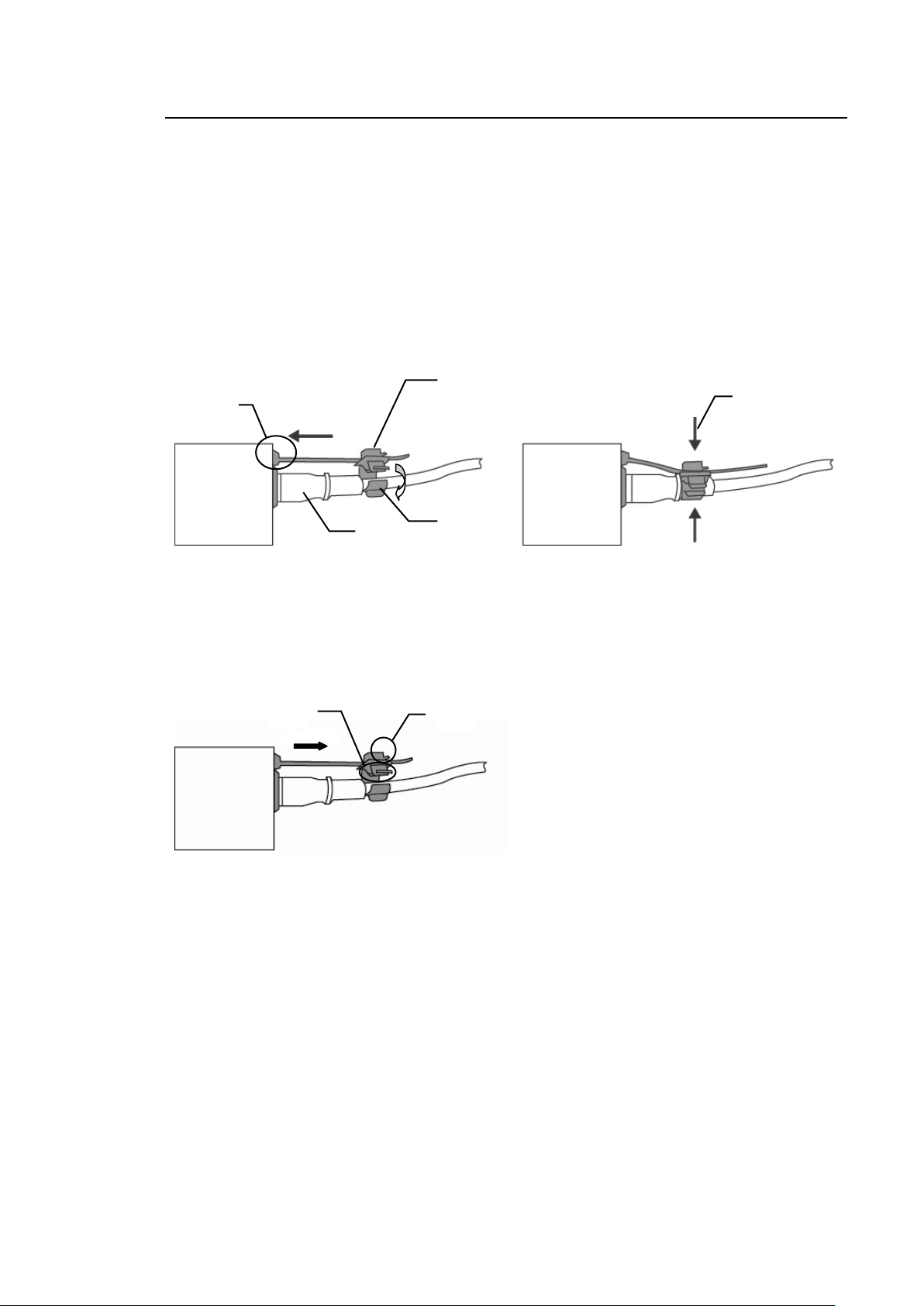
Secure the AC cord with the supplied la dder strap/ retain ing clip assembly to prev ent accident al
removal from the FA-9500.
Installing the clip
1) Wrap the retaining clip around the AC cord. (with the anchor of the ladder strap toward the
unit.)
2) Insert the anchor into the hole next to the AC IN socket.
3) Lightly fasten the clip around the AC cord.
4) Plug in the power cord.
5) Slide the clip on the ladder strap toward the plug.
6) Fasten the clip tightly.
7) Gently pull on the AC cord to ensure it is secured.
2)
4)
5)
6)
3)
Unpluging the AC cord
1) Push the tab on the retaining up to unfasten the clip.
2) Push the tab on the ladde r strap up and slide the clip back.
3) Unplug the AC cord.
1)
2)
vii
Page 8

Table of Contents
1. Prior to Starting ........................................................................................................................... 1
1-1. Welcome .............................................................................................................................. 1
1-2. Features ............................................................................................................................... 1
1-3. FA-95LG GUI Download ...................................................................................................... 1
2. Panel Descriptions ...................................................................................................................... 2
2-1. Front Panel ........................................................................................................................... 2
2-2. Rear Panel ........................................................................................................................... 3
2-3. Internal Settings ................................................................................................................... 6
2-3-1. Dipswitch Settings ......................................................................................................... 6
3. Connections ................................................................................................................................ 7
3-1. For HD /SD-SDI Frame Synchronizer Use .......................................................................... 7
3-2. For HD/SD-SDI Simultaneous Output ................................................................................. 8
3-3. To Embed AES Input Si gnals on SDI Signals ..................................................................... 9
3-4. To Embed Analog Audio Signals on SDI Signals .............................................................. 10
3-5. Connecting a Computer ..................................................................................................... 11
3-6. Connecting to the REMOTE (GPI) Connector ................................................................... 12
4. Front Panel Operations ............................................................................................................. 13
4-1. Powering ON ...................................................................................................................... 13
4-2. Basic Operations ................................................................................................................ 13
4-2-1. Accessing Menus ........................................................................................................ 14
4-2-2. Menu Buttons .............................................................................................................. 15
4-2-3. Arrow Buttons .............................................................................................................. 16
4-2-4. Consecutive Viewin g of S et t ings ................................................................................ 17
4-2-5. Page Jump Feature
4-2-6. Changing Setting V alu es ............................................................................................ 18
4-2-7. Resetting to Default .................................................................................................... 18
5. VIDEO Menus ........................................................................................................................... 19
5-1. VIDEO PRO C AMP (PROCES S) ...................................................................................... 19
5-2. COLOR CORRECTOR ( C.C.) ........................................................................................... 19
5-2-1. WHITE LEVEL ............................................................................................................ 19
5-2-2. BLACK LEVEL ............................................................................................................ 20
5-2-3. GAMMA LEVEL .......................................................................................................... 20
5-2-4. COLOR CORRECT (C. C.) .......................................................................................... 21
5-2-5. Color Corrector and AVO Modes ................................................................................ 22
5-3. CONV1 (UP /DOWN/C ROSS CONVER T ER) .................................................................... 23
5-3-1. CONV1 U/D MODE ..................................................................................................... 24
5-3-2. CONV1 Conversion Table .......................................................................................... 26
5-3-3. CONV1 SIZE/POS ...................................................................................................... 26
5-3-4. CONV1 C ROPPING ................................................................................................... 27
5-3-5. CONV1 IMPROVE ...................................................................................................... 28
5-3-6. CONV1 SIDE RGB ..................................................................................................... 29
.................................................................................................... 17
viii
Page 9

5-4. CONV2 (UP / DOWN / CROSS CONVERTER) ............................................................... 30
5-4-1. CONV2 U/D MODE .................................................................................................... 31
5-4-2. CONV2 Conversion Table .......................................................................................... 32
5-4-3. CONV2 SIZE/POS ..................................................................................................... 32
5-4-4. CONV2 C ROPPING ................................................................................................... 33
5-4-5. CONV2 IMPROVE ..................................................................................................... 34
5-4-6. CONV2 SIDE RGB ..................................................................................................... 35
5-5. Auto Video Optimizer ( AVO) ............................................................................................. 36
5-5-1. AVO SETTING ........................................................................................................... 36
5-5-2. AVO SETUP ............................................................................................................... 37
5-5-2-1. About Scene Cut Detection and Frame Delay Set t ings ..................................... 38
5-5-3. USER1 - 5 LEVEL SE T .............................................................................................. 39
5-5-4. USER1, 2 A REA SET ................................................................................................ 42
5-5-4-1. Manual Level Adjustment .................................................................................... 43
5-6. CLIP (VIDEO CLIP) ........................................................................................................... 44
5-6-1. YPbPr/RGB CLIP ....................................................................................................... 44
5-6-2. COMPOSITE CLIP ..................................................................................................... 45
5-6-3. VIDEO CLIP Settin g Ran ges ..................................................................................... 45
5-7. VIDEO INPUT SELECT (IN SEL) ..................................................................................... 47
5-7-1. VIDEO INPUT SET .................................................................................................... 47
5-7-2. SD INPUT ASPECT ................................................................................................... 48
5-7-3. About Changeover
5-7-3-1. Changeover and Loss Operation ........................................................................ 48
5-7-3-2. Changeover and I nput Sw it chover Using a Router ............................................ 48
5-7-3-3. How to Reset to SDI 1 (Main I nput ) .................................................................... 48
5-7-4. CHGOV (CHANGEOVER) MODE SET ..................................................................... 49
5-7-5. SDI ERROR TRG ....................................................................................................... 50
5-7-6. FORMAT ERROR TRG ............................................................................................. 50
5-7-7. CRC ERROR TRG ..................................................................................................... 51
5-7-8. BLACK VI DEO TRG ................................................................................................... 51
5-7-9. AUDIO LOSS TRG ..................................................................................................... 52
5-7-10. AUDIO ERR TRG ..................................................................................................... 52
5-7-11. SILENCE TRG ......................................................................................................... 53
5-7-12. CHGOV STATUS ..................................................................................................... 53
5-7-13. CHGOV VID STATUS .............................................................................................. 54
5-7-14. CHGOV AUD STATUS ............................................................................................ 54
5-7-15. AUD LOSS STATUS ................................................................................................ 55
5-7-16. AUD ERROR STATUS ............................................................................................ 55
5-7-17. SILENCE STATUS ................................................................................................... 55
5-8. VIDEO OUT SELECT (OUT SEL) ..................................................................................... 56
5-8-1. SDI1/2 OUT SET ........................................................................................................ 56
5-8-2. SDI3/4 OUT SET ........................................................................................................ 56
5-8-3. COMPOSITE SET ...................................................................................................... 57
5-8-4. COMPONENT SET .................................................................................................... 58
5-9. VIDEO OPTION (VIDEO OP) ........................................................................................... 59
..................................................................................................... 48
ix
Page 10

5-9-1. Logo Generator ........................................................................................................... 59
5-9-1-1. CONV1 LOGO SEL ............................................................................................. 59
5-9-1-2. CONV1 KEYER SET ........................................................................................... 60
5-9-1-3. CONV2 LOGO SEL ............................................................................................. 61
5-9-1-4. CONV2 KEYER SET ........................................................................................... 62
5-9-1-5. Logo Position Sett ing Range ............................................................................... 62
5-10. VIDEO SYSTEM (VIDEO S YS) ....................................................................................... 63
5-10-1. FS MODE SET .......................................................................................................... 63
5-10-2. FREEZE SET ............................................................................................................ 64
5-10-3. COMPOSI TE SE T .................................................................................................... 65
5-10-4. VIDEO SUB ............................................................................................................... 66
5-10-5. TEST SIGNAL ........................................................................................................... 66
5-10-6. HD PHASE SET ........................................................................................................ 67
5-10-7. SD PHASE SET ........................................................................................................ 68
5-10-8. VIDEO POSITION ..................................................................................................... 69
5-10-9. CONV1 ANC SET ..................................................................................................... 70
5-10-10. CONV2 ANC SET ................................................................................................... 71
5-10-11. CONV1 AUDIO GROUP ......................................................................................... 72
5-10-12. CONV2 AUDIO GROUP ......................................................................................... 72
5-10-13. SD LINE MASK ....................................................................................................... 73
5-10-14. ANC DETECT LINE ................................................................................................ 73
5-10-15. ANC DETECT SEL ................................................................................................. 74
5-10-16. ANC DATA EMBED ................................................................................................ 74
5-10-17. ANC EMBED LINE .................................................................................................. 75
5-10-18. ANC LOSS SET ...................................................................................................... 77
5-10-19. WSS AFD ERROR .................................................................................................. 78
5-11. NTSC SETUP .................................................................................................................. 79
5-12. PAL-M MODE SET .......................................................................................................... 79
5-13. Various Signal Statu s Di spl ay (STATUS) ........................................................................ 80
5-13-1. UNIT ALARM ............................................................................................................ 80
5-13-2. VIDEO IN STATUS ................................................................................................... 81
5-13-3. COMPONENT INPUT ............................................................................................... 82
5-13-4. VIDEO OUT STATUS ............................................................................................... 82
5-13-5. COMPONENT OUTPUT ........................................................................................... 83
5-13-6. SOURCE AUDIO ...................................................................................................... 84
5-13-7. SDI 1 IN AUDIO ........................................................................................................ 85
5-13-8. SDI 2 IN AUDIO ........................................................................................................ 86
5-13-9. AES IN AUDIO .......................................................................................................... 87
5-13-10. ANALOG IN AUDIO ................................................................................................ 87
5-13-11. SDI 1/2 OUT AUDIO ............................................................................................... 88
5-13-12. SDI 3/4 OUT AUDIO ............................................................................................... 89
5-13-13. AES OUT AUDIO .................................................................................................... 89
5-13-14. ANALOG OUT AUDIO ............................................................................................ 90
5-13-15. Dolby AUX STATUS ............................................................................................... 90
5-13-16. AFD IN STATUS ..................................................................................................... 91
x
Page 11

5-14. ANC IN S T ATUS ............................................................................................................. 91
5-15. ANC IN S T ATUS 1-2 ....................................................................................................... 92
5-16. CONV1 ANC OUT ........................................................................................................... 92
5-16-1. CONV1 S2016 OUT ................................................................................................. 92
5-16-2. CONV1 VI OUT ........................................................................................................ 93
5-16-3. CONV1 WSS OUT ................................................................................................... 93
5-17. CONV1 ANC OUT1 ......................................................................................................... 94
5-18. CONV2 ANC OUT ........................................................................................................... 94
5-18-1. CONV2 S2016 OUT ................................................................................................. 94
5-18-2. CONV2 VI OUT ........................................................................................................ 95
5-18-3. CONV2 WSS OUT ................................................................................................... 95
5-19. CONV2 ANC OUT1 ......................................................................................................... 96
6. AUDIO Settings ........................................................................................................................ 97
6-1. SDI AUDIO Settings (SDI AUDIO) .................................................................................... 97
6-1-1. SDI AUDIO GAIN ....................................................................................................... 97
6-1-2. SDI REMA PP ING ....................................................................................................... 98
6-1-3. SDI MONO SUM ...................................................................................................... 100
6-1-4. SDI AUDIO CLOCK ................................................................................................. 100
6-1-5. SDI IN AUDIO .......................................................................................................... 101
6-2. AES AUDIO Settings (AES AUDIO) ............................................................................... 102
6-2-1. AES IN GAIN ............................................................................................................ 102
6-2-2. AES HYST ERESIS .................................................................................................. 102
6-2-3. AES REMAPPING ................................................................................................... 103
6-2-4. AES MONO SUM ..................................................................................................... 105
6-2-5. AES I/O SETUP ....................................................................................................... 105
6-3. ANALOG AUDIO Settings (ANALOG) ............................................................................ 106
6-3-1. ANALOG IN LEVEL ................................................................................................. 106
6-3-2. ANALOG IN GAIN .................................................................................................... 106
6-3-3. ANALOG OUT LEVEL ............................................................................................. 106
6-3-4. ANALOG OUT GAIN ................................................................................................ 107
6-3-5. ANALOG REMAPPING ............................................................................................ 107
6-3-6. ANALOG MONO SUM ............................................................................................. 108
6-3-7. ANALOG SYSTEM .................................................................................................. 108
6-4. MASTER OUT GAIN Set tings (MAST ER) ...................................................................... 109
6-5. AUDIO MAPPING (MAPPING) ....................................................................................... 110
6-5-1. SOURCE/SRC SEL ................................................................................................. 110
6-6. AUDIO DELAY Settings .................................................................................................. 111
6-6-1. AUDIO DELAY ......................................................................................................... 111
6-7. DOWN MIX SET .............................................................................................................. 112
6-7-1. DOWN MIX ASSIGN ................................................................................................ 114
6-8. AUDIO MODE SET (MODE) ........................................................................................... 114
6-9. AUDIO OPTION (AUDIO OP) ......................................................................................... 115
6-9-1. Dolby AUX OUTPUT ................................................................................................ 115
6-9-2. Dolby DE CODER INPU T ......................................................................................... 116
xi
Page 12

6-9-3. Dolby DE CODER REFERENCE .............................................................................. 117
6-9-4. Dolby DOWNMIX ...................................................................................................... 117
6-9-5. Dolby DE CODER GAIN ............................................................................................ 117
6-9-6. Dolby EN CODER INPU T .......................................................................................... 118
6-9-7. Dolby EN CODER SETTING ..................................................................................... 119
6-9-8. METADATA INPUT ................................................................................................... 119
6-10. AUDIO SYSTEM Settings (AUDIO SYS) ....................................................................... 120
6-10-1. FADE IN / OUT ....................................................................................................... 120
6-10-2. DIGITAL AUDIO ...................................................................................................... 121
6-10-3. AUDIO ERR SENSE ............................................................................................... 121
6-10-4. DIGITAL SILENCE .................................................................................................. 123
7. Other Settings & Informat ion (O THER) ................................................................................... 124
7-1. CONTROL SETTING ....................................................................................................... 124
7-2. FRONT PANEL SET ........................................................................................................ 124
7-3. GPI SETTING .................................................................................................................. 125
7-4. NETWORK INFO ............................................................................................................. 128
7-5. UNIT Ver. ......................................................................................................................... 128
7-6. OPTION A Ver. ................................................................................................................ 129
7-7. OPTION B Ver. ................................................................................................................ 129
7-8. OTHER OPTION .............................................................................................................. 130
7-9. SOFT OPTION1 ............................................................................................................... 130
7-10. SOFT OPTION2 ............................................................................................................. 130
8. Event Memory ......................................................................................................................... 131
8-1. EVENT LOAD .................................................................................................................. 131
8-2. EVENT SAVE ................................................................................................................... 132
8-3. EVENT SETUP ................................................................................................................ 132
8-4. Parameters That Are Not St or ed in Event Memories ...................................................... 133
8-5. Note on Event Memor y Operation ................................................................................... 133
9. Control via WEB Browser ........................................................................................................ 134
9-1. Connecting via a WEB Browser ....................................................................................... 134
9-2. VIDEO Settings ................................................................................................................ 135
9-2-1. Input Select ............................................................................................................... 136
9-2-1-1. About Changeover (Web) .................................................................................. 140
9-2-1-2. Changeover and Loss Operation (Web) ............................................................ 141
9-2-1-3. Changeover and I nput Sw it chover Using a Router (Web) ................................ 141
9-2-1-4. How to Reset to SDI 1 (Main I nput ) (Web) ........................................................ 141
9-2-2. Auto Video Optimizer ( AVO) ..................................................................................... 142
9-2-2-1. About Scene Cut Detection and Frame Delay Set t ings .................................... 144
9-2-2-2. User 1 - 5 LEVEL SET ....................................................................................... 145
9-2-2-3. User Area 1, 2 .................................................................................................... 147
9-2-3. Frame Delay .............................................................................................................. 148
9-2-4. Proc Amp .................................................................................................................. 149
9-2-5. BY-PASS / Operate .................................................................................................. 149
9-2-6. Converter1 ................................................................................................................ 150
xii
Page 13

9-2-7. Converter2 (Up/Down/Cross) ................................................................................... 154
9-2-8. Color Corrector ......................................................................................................... 158
9-2-9. Video Test Signal ..................................................................................................... 160
9-2-10. YPbPr/ RGB Clip ..................................................................................................... 161
9-2-11. Output Select .......................................................................................................... 162
9-2-12. Composite Clip ....................................................................................................... 164
9-3. AUDIO Settings ............................................................................................................... 165
9-3-1. SDI Input Gain .......................................................................................................... 166
9-3-2. AES Audio Input Sett ings ......................................................................................... 167
9-3-3. Analog Input Gain/Level ........................................................................................... 169
9-3-4. Source Select ........................................................................................................... 170
9-3-5. Audio Output Delay .................................................................................................. 171
9-3-6. SRC Mode ................................................................................................................ 172
9-3-7. Audio Master Settings .............................................................................................. 173
9-3-8. Audio Test Signal ..................................................................................................... 174
9-3-9. 5.1Ch Down Mix ....................................................................................................... 175
9-3-10. Audio Output Polar it y ............................................................................................. 177
9-3-11. SDI Audio Output Sett ings ..................................................................................... 178
9-3-12. AES Audio Output Set t ings .................................................................................... 181
9-3-13. Analog Audio Output Set t ings ................................................................................ 184
9-3-14. Dolby E/Digital Dec oder ......................................................................................... 185
9-3-15. Dolby AUX OUTPUT Select
9-3-16. Dolby E Encoder .................................................................................................... 189
9-4. SYSTEM Settings ............................................................................................................ 191
9-4-1. Video System ........................................................................................................... 191
9-4-2. Audio System ........................................................................................................... 198
9-4-3. ANC Settings ............................................................................................................ 202
9-5. GPI ................................................................................................................................... 206
9-6. Utility Settings .................................................................................................................. 208
9-6-1. Event Control ............................................................................................................ 209
9-6-2. Backup Parameter ................................................................................................... 210
9-6-3. Downloading a MIB File ........................................................................................... 212
9-6-4. Backup Event Data .................................................................................................. 213
9-7. Status Display .................................................................................................................. 215
9-7-1. Unit/Video Status ..................................................................................................... 215
9-7-2. Audio Status ............................................................................................................. 218
9-7-3. Unit Information ........................................................................................................ 221
9-7-4. ANC Status ............................................................................................................... 222
9-7-5. Changeover Status .................................................................................................. 225
9-8. Network Settings ............................................................................................................. 227
9-8-1. Network Information ................................................................................................. 227
9-8-2. NETWORK SETTING .............................................................................................. 227
9-8-3. SNMP SETTING ...................................................................................................... 228
9-8-4. TRAP SETTINGS
9-8-5. USER SETTING ....................................................................................................... 231
................................................................................... 188
..................................................................................................... 230
xiii
Page 14

9-8-6. Restart ....................................................................................................................... 231
10. Systen Block Diagram ( Audi o) .............................................................................................. 232
11. ANALOG/DIGITAL Audio Input/Output Level ....................................................................... 233
11-1. Analog Output Level Relative to the Digital Input Level ................................................ 233
11-2. Digital Output Leve l Re lative to the Analog Input Level ................................................ 234
12. Analog Audio Connection ...................................................................................................... 235
13. Dolby E Decoder/Encoder C hannel Assignment Table ........................................................ 236
14. REMOTE ............................................................................................................................... 237
14-1. REMOTE Connector ...................................................................................................... 237
14-2. GPI Input Circuit ............................................................................................................. 237
14-3. GPI Input Control ........................................................................................................... 238
14-4. GPI Output Circuit .......................................................................................................... 239
15. How to Install the FA-95DACBL ............................................................................................ 240
15-1. Procedure ....................................................................................................................... 240
15-2. Installation Confir m ation ................................................................................................ 241
16. FA-95AIO Option ................................................................................................................... 242
16-1. FA-95AIO Pin Assignments ........................................................................................... 242
16-2. FA-95AIO Switch Settings ............................................................................................. 243
17. System Requirements ........................................................................................................... 244
18. About SNMP (Simple Netw ork Management Protoc ol) ........................................................ 245
19. FA-9500 Ancillary Data Packet Name List ............................................................................ 256
20. About AFD (Active Format Description) ................................................................................ 258
20-1. AFD Codes ..................................................................................................................... 259
20-2. Aspect Ratio Conversion with AFD ................................................................................ 261
20-3. AFD Supported Vid eo Formats ...................................................................................... 265
20-4. AFD Based Auto Aspec t Co nversion Settings ............................................................... 265
20-5. How to Insert AFD Data to O ut put Video Signals .......................................................... 266
20-6. AFD Code Abbrevia tions ............................................................................................... 267
20-7. Conversion Setting Vers ion Differe nces ........................................................................ 268
21. About Colosed Captioning .................................................................................................... 269
21-1. Closed Captioning Set t ing Procedure ............................................................................ 269
22. Loading Older Version Data from FA-9500 .......................................................................... 270
23. Regarding Option Card Removal .......................................................................................... 271
23-1. Alert ................................................................................................................................ 271
23-2. Items To Be Verified After Dolby Option Remov al ........................................................ 271
23-3. Items To Be Verified After FA-95AIO Option Removal ................................................. 271
24. Expansion Slots A / B Alert ................................................................................................... 272
25. Specifications and Di me nsions ............................................................................................. 273
25-1. Unit Specifications .......................................................................................................... 273
xiv
Page 15

25-2. External Dimensions ..................................................................................................... 276
Index ........................................................................................................................................... 277
xv
Page 16

Page 17

1. Prior to Starting
1-1. Welcome
Congratulations! By purchasing FA-9500 Frame Synchronizer you have entered the world of
FOR-A and its many innovative products. Thank you for your patronage and we hope you will
turn to FOR-A products again and again to satisfy your video and audio needs.
FOR-A provides a wide range of products, from basic support units to complex system
controllers, which have been increasingly joined by products for computer video based systems.
Whatever your needs, talk to your FOR-A representative. We will do our best to be of continuing
service to you.
1-2. Features
The FA-9500 is a multipurpose signal processor loaded with all the functions you need for video
production.
3G-SDI, HD/SD-SDI, and analog composite I/O is supported in addition to its functionality as a
frame synchronizer. The unit provides dual up/down/cross/aspect converters, color corrector,
and automatic video optimizer (AVO) as standard features, allowing for the conversion of many
types of video and audio signals. Numerous additional optional features include analog
component I/O, frame rate converter, logo generator, Dolby E encoder and Dolby E decoder. By
combining these varied options, a single unit can provide optimal functionality for all your video
production scene requirements, including line, relay, reporting, production, editing and delivery.
If you have the FA-9500, you will never need another piece of peripheral video equipment!
Standard Features
3G-SDI/HD-SDI/SD-SDI/Analog Composite I/O
Digital/Analog Audio I/O
Main Converter (Up/Down/Cross/Aspect conversion)
Second Converter (Up/Down/Cross/Aspect conversion)
Color Corrector
Auto Video Optimizer (AVO)
Powerful Frame Synchronizer Performance
Logo Generator
Other Features
Video delay
2D/3D comb filter for Y/C separator (composite)
Web browser-based monitoring and control possible
SNMP monitoring and partial control function
Additional Features
Redundant power supply unit
Changeover function
Remote control unit via Ethernet
Dolby E/Digital decoder and Dolby E encoder
Analog component I/O
1-3. FA-95LG GUI Download
The FA-9500 Logo generator function is designed to be used with logo management software,
FA-95LG GUI, enabling logo data import to FA-9500 via Ethernet. The FA-95LG GUI can be
downloaded from FOR-A’s website: http://www.for-a.com/products/fa9500/fa95lg_gui.zip
operation manual for the FA-95LG GUI will download automatically along with the software.
1
. The
 Loading...