

Page 1
OPERATION
MANUAL
DCC-100
Digital Color Corrector
nd
Edition
2
Page 2

Page 3
Precautions
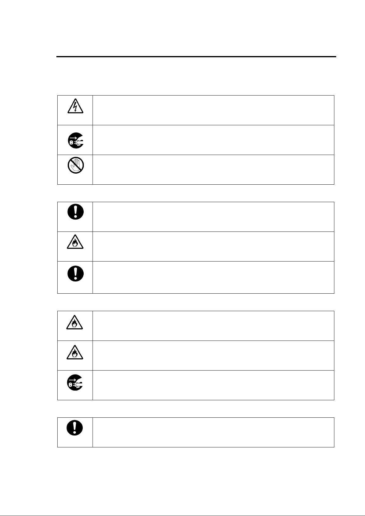
Important Safety Warnings
[Power]
Caution
Stop
[Grounding]
Caution
Hazard
Caution
Operate unit only on the specified supply voltage.
Disconnect power cord by connector only. Do not pull on cable portion.
Do not place or drop heavy or sharp-edged objects on power cord. A damaged cord
can cause fire or electrical shock hazards. Regularly check power cord for
excessive wear or damage to avoid possible fire / electrical hazards.
Ensure unit is properly grounded at all times to prevent electrical shock hazard.
Do not ground the unit to gas lines, units, or fixtures of an explosive or dangerous
nature.
Ensure power cord is firmly plugged into AC outlet.
[Operation]
Hazard
Hazard
Do not operate unit in hazardous or potentially explosive atmospheres. Doing so
could result in fire, explosion, or other dangerous results.
Do not allow liquids, metal pieces, or other foreign materials to enter the unit. Doing
so could result in fire, other hazards, or unit malfunction.
If foreign material does enter the unit, turn power off and disconnect power cord
immediately. Remove material and contact authorized service representative if
damage has occurred.
[Transportation]
Caution
Handle with care to avoid shocks in transit. Shocks may cause malfunction. When
you need to transport the unit, use the original packing materials or alternate
adequate packing.
Page 4
[Circuitry Access]
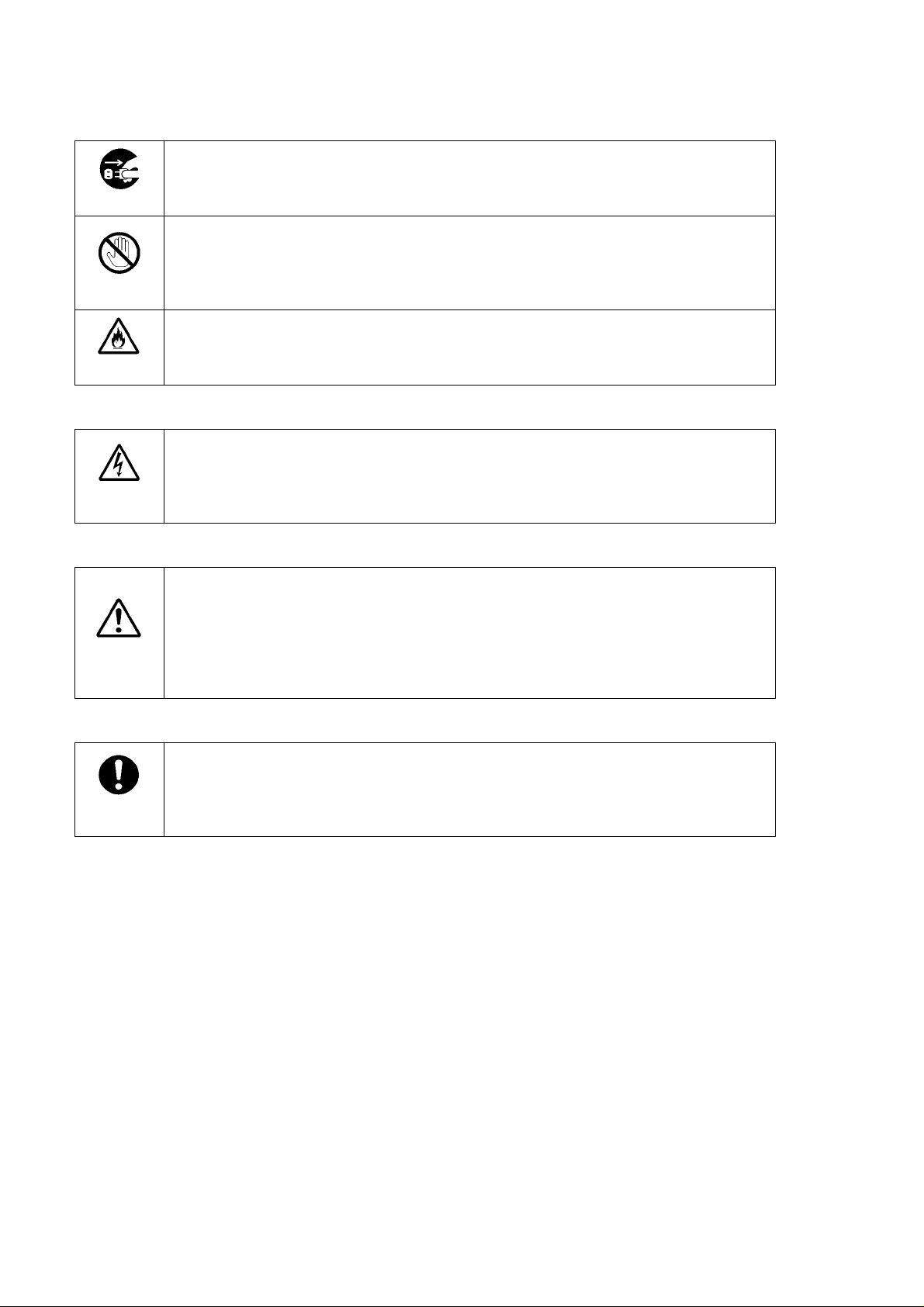
Stop
Hazard
Do not remove covers, panels, casing, or access circuitry with power applied to the
unit! Turn power off and disconnect power cord prior to removal. Internal servicing /
adjustment of unit should only be performed by qualified personnel.
Do not touch any parts / circuitry with a high heat factor.
Capacitors can retain enough electric charge to cause mild to serious shock, even
after power is disconnected. Capacitors associated with the power supply are
especially hazardous. Avoid contact with any capacitors.
Unit should not be operated or stored with cover, panels, and / or casing removed.
Operating unit with circuitry exposed could result in electric shock / fire hazards or
unit malfunction.
[Potential Hazards]
Caution
If abnormal smells or noises are noticed coming from the unit, turn power off
immediately and disconnect power cord to avoid potentially hazardous conditions. If
problems similar to above occur, contact authorized service representative before
attempting to again operate unit.
[Consumables]
Caution
The consumables used in unit must be replaced periodically. For further details on
which parts are consumables and when they should be replaced, refer to the
specifications at the end of the Operation Manual. Since the service life of the
consumables varies greatly depending on the environment in which they are used,
they should be replaced at an early date. For details on replacing the consumables,
contact your dealer.
[Rubber Feet]
Caution
If this product has come with rubber feet attached by screws, do not insert the
screws again without rubber feet after removing the rubber feet and screws. It may
cause damage to the internal circuits or components of the unit. To install the rubber
feet again to the unit, do not use other than the supplied rubber feet and screws.
Page 5
Upon Receipt
Unpacking
DCC-100 units and their accessories are fully inspected and adjusted prior to shipment.
Operation can be performed immediately upon completing all required connections and
operational settings.
Check your received items against the packing lists below.
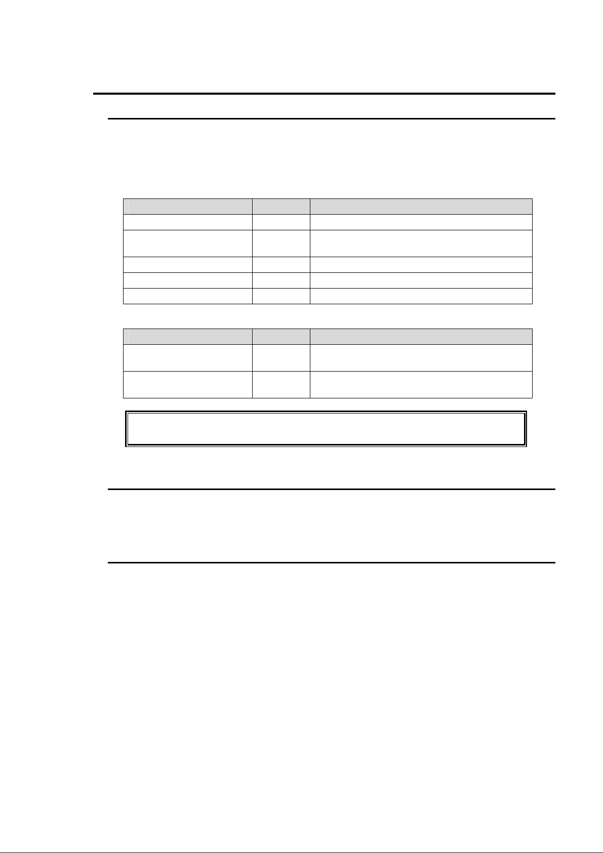
ITEM QTY REMARKS
DCC-100 1
Control Cable 1
AC Cord 1
Rack Mount Brackets 1 set
Operation Manual 1
Option
ITEM QTY REMARKS
Rack mount bracket set
(type 1)
Rack mount bracket set
(type 2)
1 set
1 set
For Main Unit and Operation Unit connection
PC-2076-2, 10m
For mounting single unit to an EIA 1RU rack
space.
For mounting two units to an EIA 1RU rack
space.
Note that DCC-OU or DCC-OUA Operation Unit is required for DCC-100 operation.
DCC-OU/OUA is a separate purchase.
Check
Check to ensure no damage has occurred during shipment. If damage has occurred, or items
are missing, inform your supplier immediately.
Rack Mounting
The DCC-100 can be either single unit or dual unit mounted to EIA standard rack units. Racking
mounting requires purchase of one of the two available rack mount kits.
When single unit mounting the single mount kit with one extended rack ear must be used. When
two units mounting the dual mount kit with standard size rack ears must be used. Consult your
FOR-A supplier to order either of these options.
Page 6

Table of Contents
1. Prior to Starting...........................................................................................................................1
1-1. Welcome............................................................................................................................1
1-2. Features.............................................................................................................................1
1-3. About This Manual..............................................................................................................1
2. Panel Descriptions ..................................................................................................................... 2
2-1. Front Panel......................................................................................................................... 2
2-2. Rear Panel .........................................................................................................................3
3. Connection.................................................................................................................................4
3-1. Connection Example 1.......................................................................................................4
3-2. Connection Example 2.......................................................................................................5
4. Operation ...................................................................................................................................6
4-1. Power On...........................................................................................................................6
4-2. Front Panel Operations......................................................................................................6
4-2-1. INPUT SELECT..........................................................................................................6
4-2-2. SPLIT.........................................................................................................................7
4-3. Remote Control..................................................................................................................8
4-3-1. REMOTE Connector ..................................................................................................8
5. Internal Setting...........................................................................................................................9
5-1. Dipswitch Settings.............................................................................................................. 9
5-1-1. SW1 ...........................................................................................................................9
5-1-2. SW2 ......................................................................................................................... 11
5-1-3. SW3 (SETUP Setting).............................................................................................. 13
5-2. Jumper Settings ............................................................................................................... 14
5-2-1. COMPOSITE OUT 2 / GENLOCK IN Switching.......................................................14
6. If Problems Occur.....................................................................................................................15
7. Specifications & Dimensions....................................................................................................16
7-1. Unit Specifications............................................................................................................16
7-2. External Dimensions ........................................................................................................18
7-2-1. Single Unit................................................................................................................18
7-2-2. Rack Mounting Examples......................................................................................... 19
Page 7

1. Prior to Starting
1-1. Welcome
Congratulations! By purchasing DCC-100 Digital Color Corrector you have entered the world of
FOR-A and its many innovative products. Thank you for your patronage and we hope you will
turn to FOR-A products again and again to satisfy your video and audio needs.
FOR-A provides a wide range of products, from basic support units to complex system
controllers, which have been increasingly joined by products for computer video based systems.
Whatever your needs, talk to your FOR-A representative. We will do our best to be of continuing
service to you.
1-2. Features
This is a digital color corrector that supports analog composite or SD-SDI input and output
signals. It comes with a broad spectrum of functions ranging from the color correction of signals
to various clip functions.
Analog composite or SD-SDI input and output signals supported.
4:2:2 digital component signal processing.
10-bit digital Y/C separation/decoding/encoding.
Full frame memory to prevent picture field inversion during processing.
A-to-D or D-to-A conversion function.
Varied color correction functions (Balanced, Differential and Sepia modes)
Gamma adjustment functions (independent adjustment of G, B and R signals, center/
black/white tone adjustment)
Functions for adjusting white, black and gamma levels either independently or as a group.
YPbPr clip functions
Proc Amp functions (video level, Y level, chroma level, chroma phase and setup level).
Function for dividing the screen into sections to make it easier to compare and check the
images before and after correction.
Control of up to four units enabled by using the DCC-OU or DCC-OUA remote control unit
(option).
Compact EIA 1RU half width. Rack mountable with an optional rack mount bracket set.
1-3. About This Manual
This manual is intended to help the user easily operate this product and make full use of its
functions during operations. Before connecting or operating your unit, read this operation
manual thoroughly to ensure you understand the product. After reading, it is important to keep
this manual in a safe place and available for reference.
1
Page 8
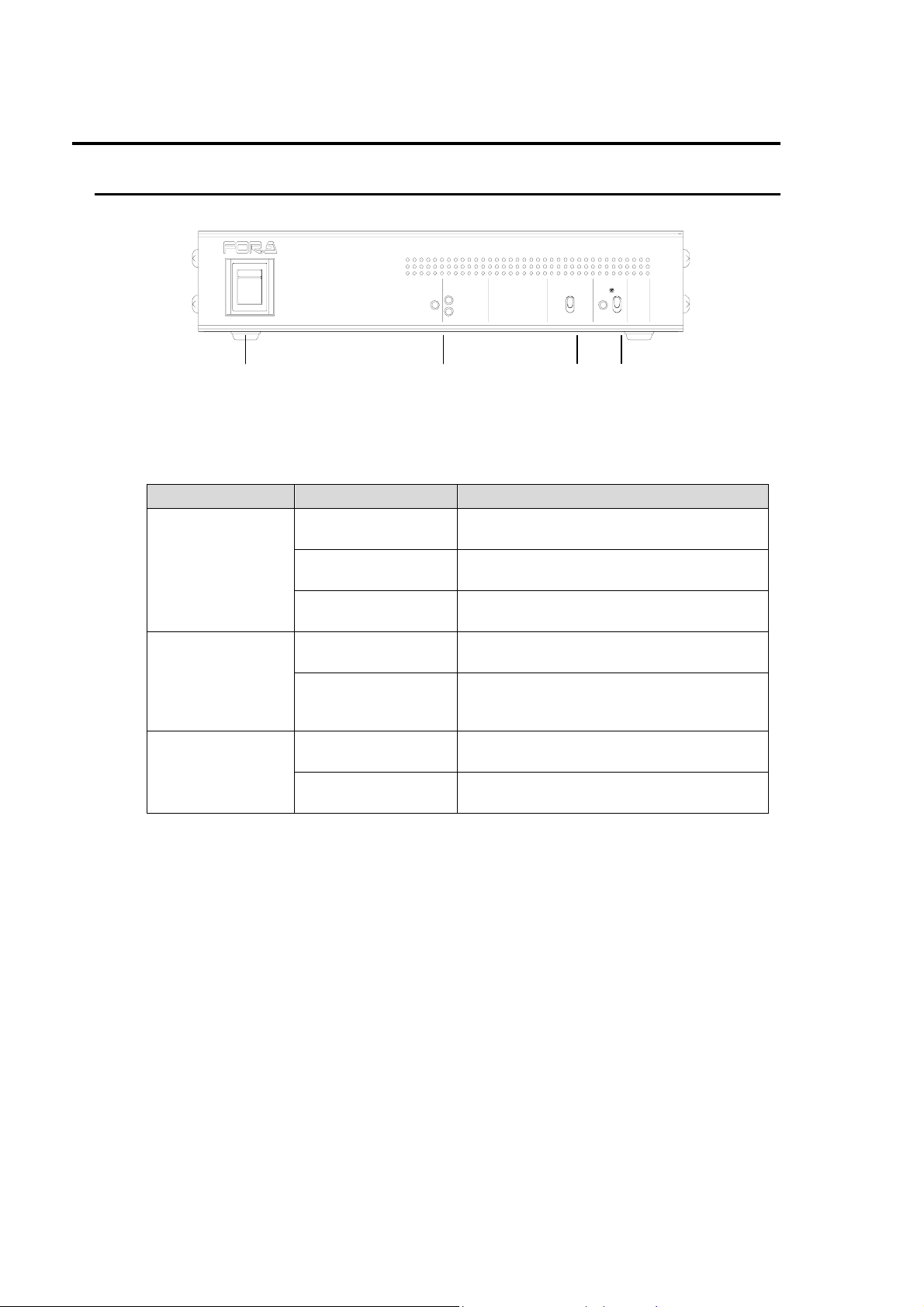
2. Panel Descriptions
2-1. Front Panel
ON
POWER
ON
OFF
OFF
POWER
COMPOSITE IN
SD-SDI IN
DIGITAL COLOR CORRECTOR
(2) (3) (4)(1)
(1) POWER switch
Used to turn power on or off.
(2) Indicators: POWER, COMPOSITE IN and SD-SDI IN
Indicator Indication Status
Indicates that power is supplied to the
system, and the system is operational.
Indicates that no power is supplied to the
system.
Indicates a fan failure occurs in a power
supply. Consult your FOR-A supplier.
Receiving composite signal input and the
unit is working properly.
No input video signals.
Input level too low.
POWER
COMPOSITE IN
Lit green
Unlit
Flashing
(Fan Alarm)
Lit green
Unlit
Off video random noise.
Lit green
SD-SDI IN
Unlit
Receiving SD-SDI signal input and the unit
is working properly.
No input video signals.
Input level too low.
(3) INPUT SELECT
Used to switch between video inputs.
Toggling the switch upward selects COMPOSITE IN and toggling downward selects
IN. See section. 4-2-1. "INPUT SELECT."
(4) SPLIT
Used to select a split screen mode (for processed and original images). See section 4-2-2.
"SPLIT." SPLIT mode is turned OFF when you start up the unit.)
INPUT SELECT
COMPOSITE
SD-SDI
DCC-100
SPLIT
ON
OFF
SD-SDI
2
Page 9
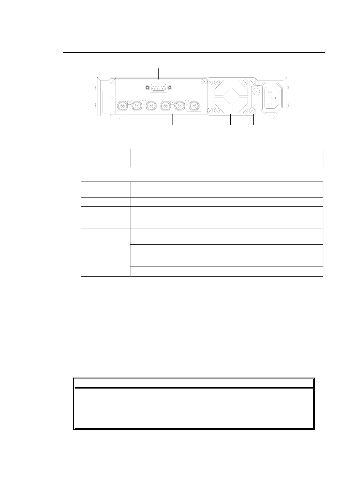
2-2. Rear Panel
(3)
REMOTE
SER.NO.
INPUT
OUTPUT
COMPOSITE 2COMPOSITE 1SD-SDI 2SD-SDI 1SD-SDICOMPOSITE
UFM-100DCC
AC100-240V
50/60Hz IN
(1) (2) (4) (6) (5)
(1) INPUT
COMPOSITE Used to input analog composite video.
SD-SDI Used to input SD-SDI signal.
(2) OUTPUT
SD-SDI 1
Used to output processed SD-SDI signal. Used to bypass the signal
(1) INPUT SD-SDI whenever the unit power is off.
from
SD-SDI 2 Used to output processed SD-SDI signal.
Used to output processed analog composite signal. Used to bypass
COMPOSITE 1
the signal from (1) INPUT COMPOSITE whenever the unit power is
off.
Switching between COMPOSITE 2 and GENLOCK IN can be made
at the jumper on MAIN CARD inside the unit.
COMPOSITE 2
COMPOSITE 2
Used to output processed analog composite
signal. See section 5-2-1. "COMPOSITE OUT 2 /
GENLOCK IN Switching."
GENLOCK IN
Used to input reference signal (black burst).
(3) REMOTE
Used to connect DCC-OU or DCC-OUA . Use the supplied control cable for the connection.
See section 3. " Connection", section 4-3-1. "REMOTE Connector" and section 5-1-2. "SW2."
(4) Cooling fan
Used to air cool unit to prevent overheating. Do not block fan intake with other equipment or
objects.
(5) Ground terminal
Used to ground unit to protect operators against static electricity and / or electrical shock.
(6) AC power input (100V-240VAC 50/60Hz)
Used for connection to AC power source via supplied accessory cord.
IMPORTANT
The unit circuitry does not have fuse protection. The unit power cord must not be
connected directly to the power source. Instead, use one of the following methods.
Connect to a power connection unit having an installed fuse.
Connect to a power connection unit having a breaker that can be easily reached in
an emergency.
3
Page 10
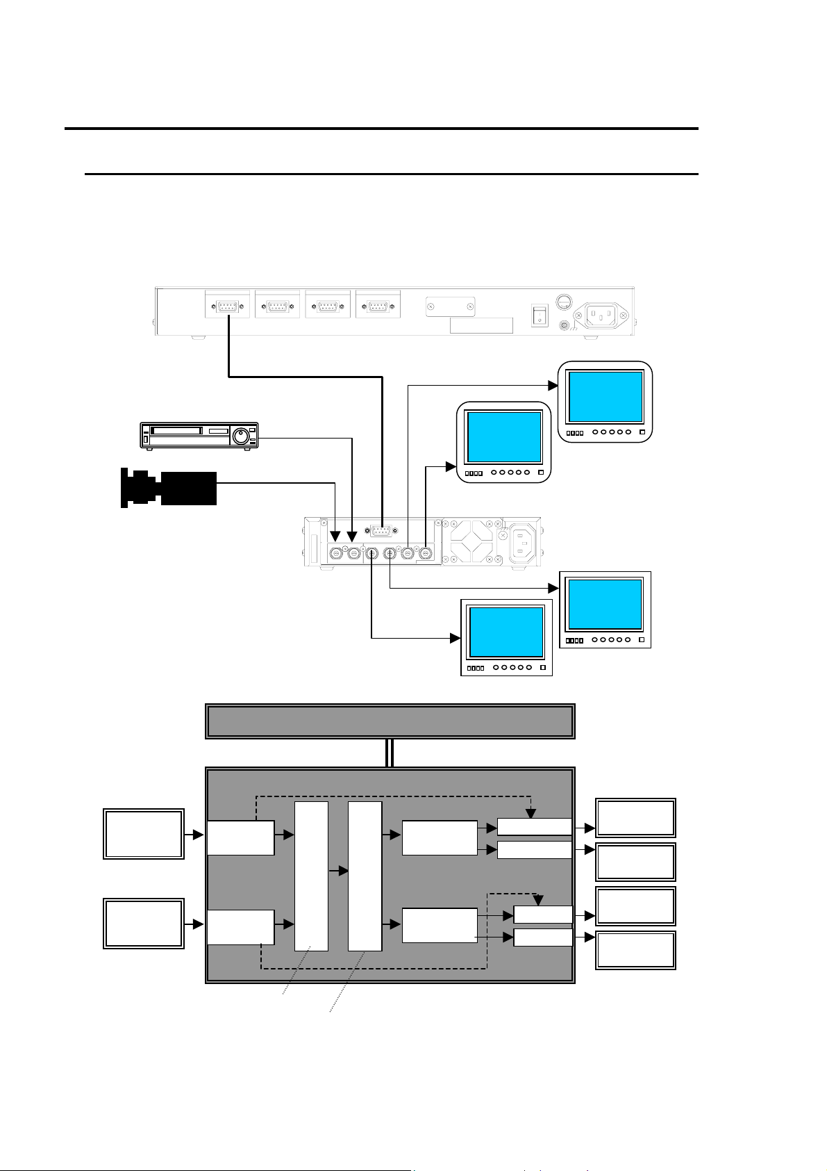
3. Connection
3-1. Connection Example 1
Use the supplied control cable (PC-2076-2) to connect a DCC-OU or a DCC-OUA to the
DCC-100. Input both SD-SDI and analog composite video signals and perform correction by
switching them.
Connection
VCR
Camera
PC-2076-2 (10m)
SD-SDI
COMPOSITE
TO MU4TO MU3TO MU2TO MU1
ON
RATING LABEL
OFF
Analog
monitor
DCC-100
REMOTE
SER.NO.
INPUT
COMPOSITE 2COMPOSITE 1SD-SDI 2SD-SDI 1SD-SDICOMPOSITE
OUTPUT
UFM-100DCC
AC100-240V
50/60Hz IN
Digital
monitor
POWER
DCC-OU
S
U
E
F
AC100- 117V ~ 5 0/60Hz IN
PUSH
Analog
monitor
Digital
monitor
Block diagram
Analog
VCR
Digital
VCR
See section 4-2-1. "INPUT SELECT."
DCC-OU/OUA
Composite
SD-SDI
DCC-OU/OUA Operation manual
INPUT SELECT
Bypass
COLOR CORRECTION
Bypass
Composite
SD-SDI
DCC-100
Composite 1
Composite 2
SD-SDI 1
SD-SDI 2
Analog
monitor
Analog
monitor
Digital
monitor
Digital
monitor
4
Page 11
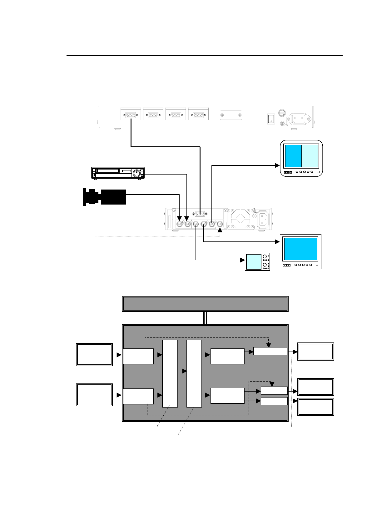
3-2. Connection Example 2
Input both SD-SDI and analog composite video signals and perform correction by switching
them. To use a reference signal, change jumper setting to use COMPOSITE OUT 2 as
GENLOCK IN. See section 5-2-1. "COMPOSITE OUT 2 / GENLOCK IN Switching."
Connection
VCR
Camera
Reference (BB)
PC-2076-2 (10m)
SD-SDI
COMPOSITE
TO MU4TO MU3TO MU2TO MU1
ON
RATING LABEL
REMOTE
SER.NO.
INPUT
COMPOSITE 2COMPOSITE 1SD-SDI 2SD-SDI 1SD-SDICOMPOSITE
OUTPUT
UFM-100DCC
OFF
DCC-100
AC100-240V
50/60Hz IN
POWER
DCC-OU
S
U
E
F
AC100- 117V ~ 5 0/60Hz IN
PUSH
Analog
monitor
Digital
monitor
Block diagram
Analog
VCR
Composite
Digital
VCR
SD-SDI
See section 4-2-1. "INPUT SELECT."
DCC-OU/OUA operation manual
DCC-OU/OUA
INPUT SELECT
COLOR CORRECTION
Bypass
Bypass
Waveform monitor
Composite
SD-SDI
DCC-100
Composite 1
SD-SDI 1
SD-SDI 2
See section 4-2-2. "SPLIT."
Analog
monitor
Waveform
monitor
Digital
monitor
5
Page 12
4. Operation
4-1. Power On
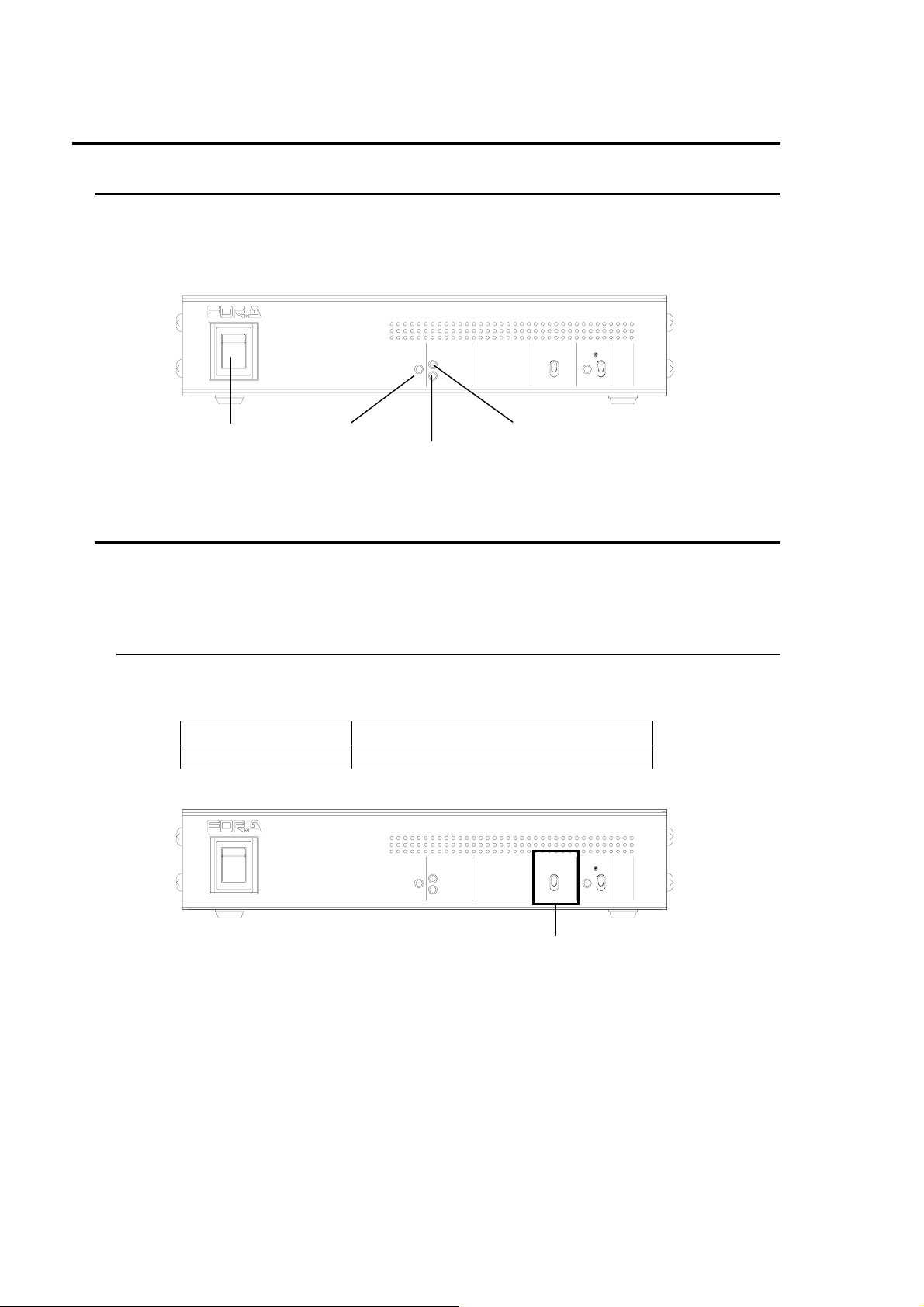
Turn Power switch to ON after all system connections are complete. When the unit is powered
ON, the green Power LED should go on. If either one (or both) of video signals is input to the unit,
the COMPOSITE IN and/or SD-SDI IN LED shown below will turn on.
ON
ON
DIGITAL COLOR CORRECTOR
POWER
OFF
OFF
POWER
COMPOSITE I N
SD-SDI IN
POWER switch COMPOSITE IN lamp
POWER lamp
SD-SDI-IN lamp
INPUT SELECT
COMPOSITE
SD-SDI
DCC-100
SPLIT
ON
OFF
4-2. Front Panel Operations
The DCC-100 front panel controls can be used to select video input (INPUT SELECT) and split
display mode (SPLIT).
4-2-1. INPUT SELECT
Set the switch to the upper or lower positions to switch the input video standard.
(When operating with DCC-OUA, change video standard from DCC-OUA.)
Up Composite input (default)
Down SD-SDI input
POWER
ON
ON
OFF
OFF
POWER
COMPOSITE I N
SD-SDI IN
DIGITAL COLOR CORRECTOR
INPUT SELECT switch
INPUT SELECT
COMPOSITE
SD-SDI
DCC-100
SPLIT
ON
OFF
6
Page 13
r
4-2-2. SPLIT
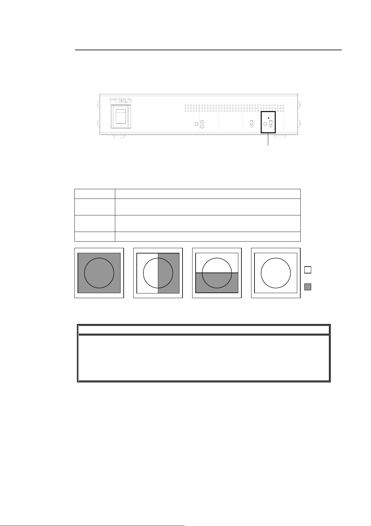
Move the switch to upward or downward to select split screen mode for COMPOSITE OUT1,
COMPOSITE OUT2, SD-SDI OUT 1 and SD-SDI OUT 2, which allows direct comparison of
images before and after correction. (When operating with DCC-OUA, change split mode from
DCC-OUA.)
ON
POWER
ON
OFF
OFF
POWER
COMPOSITE IN
SD-SDI IN
DIGITAL COLOR CORRECTOR
INPUT SELECT
Each time moving the switch up and down changes mode in the sequential order: OFF, 1, 2
and 3.
OFF Displays the image after correction.(Factory default:)
1
Splits the screen vertically and displays images before and
after correction.
2
Splits the screen horizontally and displays images before and
after correction.
3 Displays the image before correction
Mode: 1Mode: OFF Mode: 2 Mode: 3
NOTE
DCC-100
SPLIT
COMPOSITE
SD-SDI
ON
OFF
SPLIT switch
Image before
correction
Image afte
correction
SPLIT mode is OFF whenever you start up the unit.
Split mode can be set separately for COMPOSITE OUT and SD-SDI OUT. To do this,
use the internal dipswitch SW1. SW1-3 switches to enable or disable the split function
for COMPOSITE OUT. SW1-4 switches to enable or disable the split function for
SD-SDI OUT. The factory default is enabled for both. (See section 5-1-1. SW1".)
7
Page 14
4-3. Remote Control
Control DCC-100 remotely from the operation unit (DCC-OU or DCC-OUA) via REMOTE
connector on the DCC-100 rear panel.
Refer to DCC-OU or DCC-OUA operation manual for details on color correction operation.
IMPORTANT
The dipswitch SW2 inside the DCC-100 must be set according to which operation unit
is used. See section 5-1-2. "SW2."
4-3-1. REMOTE Connector
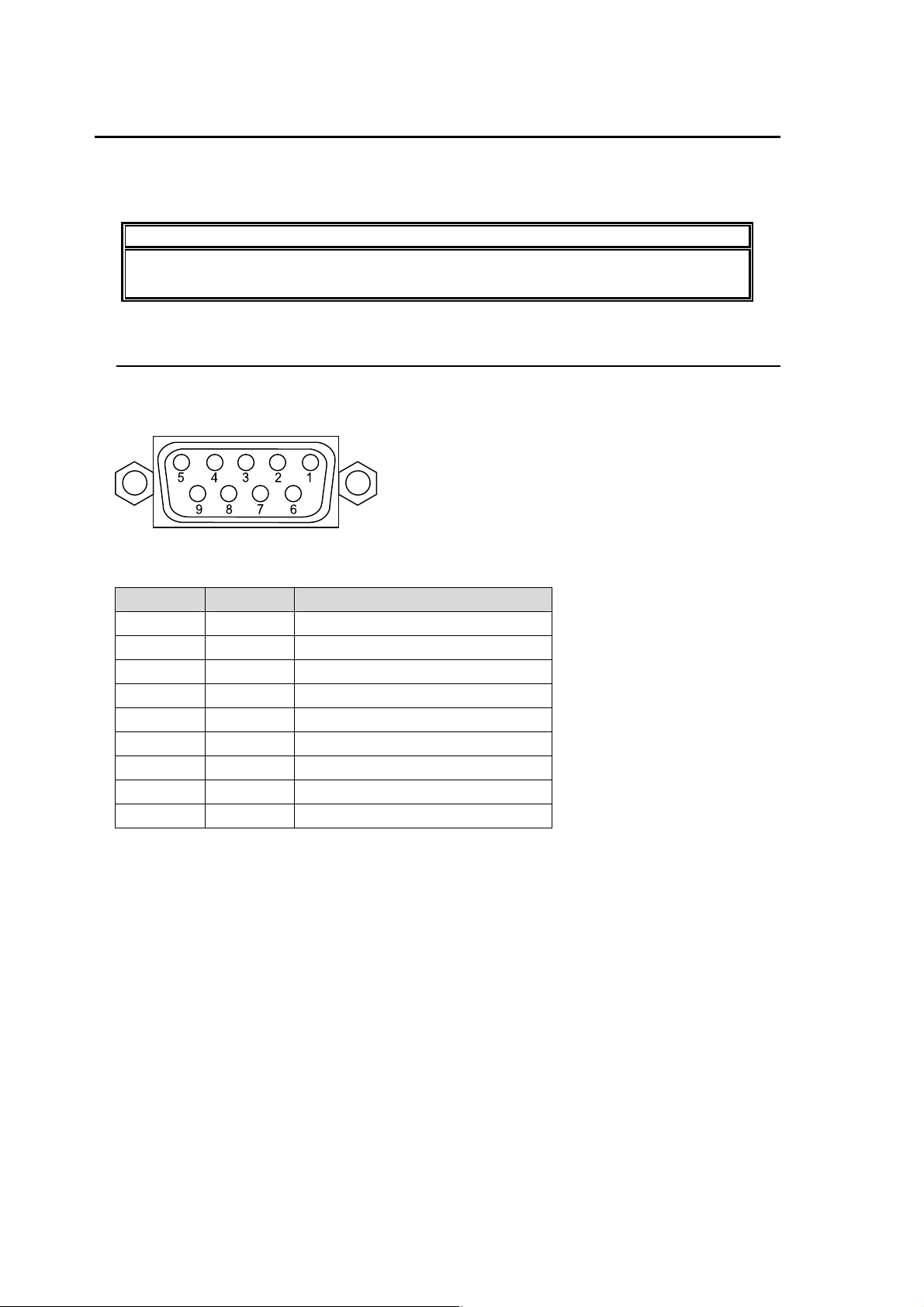
Connector Appearance
9-pin D-sub, female (inch screw type)
Pin Assignments (9-pin D-sub, female)
Pin No. Signal Description
1 Reserved Not used
2 TX(-) TRANSMIT3 RX(+) RECEIVE+
4 ― ―
5 ― ―
6 ― ―
7 TX(+) TRANSMIT+
8 RX(-) RECEIVE9 FG Frame ground
8
Page 15
5. Internal Setting
5-1. Dipswitch Settings
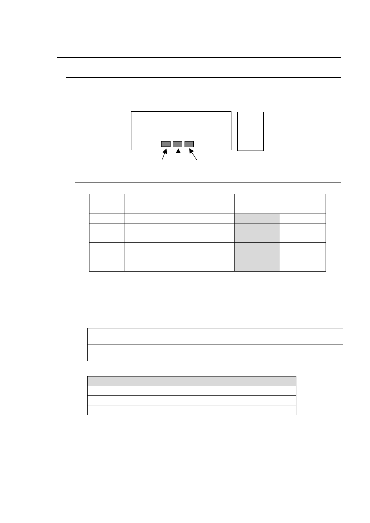
Following settings can be made at dipswitch SW1, SW2, and SW3 on the MAIN CARD.
5-1-1. SW1
Dipswitch SW1
Pin No Function
1 TEST SIGNAL ― COLOR BAR
2 SYNCHRO MODE INPUT FRAME
3 SPLIT OFF (Composite OUT) SPLIT ON SPLIT OFF
4 SPLIT OFF (SD-SDI OUT) SPLIT ON SPLIT OFF
5 VITS OFF ON
6-8 FACTORY SET ― ―
*Shaded cells indicate factory default.
MAIN CARD
SW2
SW3 SW1
I/O CARD
Setting
OFF ON
TEST SIGNAL (SW1-1)
Sets internal color bar ON/OFF.
SYNCHRO MODE (SW1-2)
INPUT
(Default)
FRAME
If set to INPUT, the delay will be as shown in the table below.
Input video format Signal delay
Composite (NTSC) Approx. 2H
Composite (PAL) Approx. 3H
If set to FRAME, a maximum I/O delay will be one frame.
Minimizes the input/output delay for the selected video signal.
Synchronizes the frame timing of the output video and reference
input. This setting is effective for input video with a lot of jitter.
SD-SDI Approx. 1H
9
Page 16
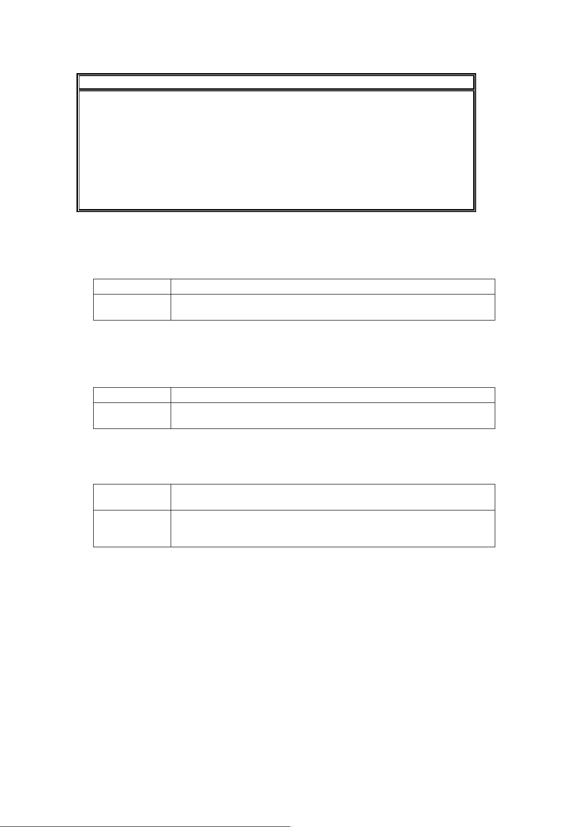
NOTE
If set to INPUT:
The amount of jitter on the SD-SDI output depends on that of input signal when
analog composite is selected for input.
Color framing is not always properly processed for COMPOSITE output when the
SD-SDI input is used.
If set to FRAME:
The composite input is horizontally locked, however, it is not correctly locked to the
subcarrier of the applied genlock.
The unit operates in free running mode when no genlock signal is input to the unit.
SPLIT OFF (Composite OUT) (SW1-3)
Enables/Disables split screen mode (split display for direct comparison of images before and
after correction) for COMPOSITE OUT.
SPLIT OFF Disables split screen mode.
SPLIT ON
(Default)
Displays split screen according to the SPLIT switch setting on the front
panel. (See section 4-2-2. "SPLIT".)
SPLIT OFF (SD-SDI OUT) (SW1-4)
Enables/Disables split screen mode (split display for direct comparison of images before and
after correction) for SD-SDI OUT.
SPLIT OFF Disables split screen mode.
SPLIT ON
(Default)
Displays split screen according to the SPLIT switch setting on the front
panel. (See section 4-2-2. "SPLIT".)
VITS (SW1-5)
Selects to pass or blank vertical interval data of composite input.
OFF
(Default)
ON
Blanks vertical interval data of composite input from 10H to 20H. No
vertical interval data is passed to the composite output.
V ertical interval data from 10H to 21H is passed to an output. I f vertical
interval data is included in the composite input, it is also included in the
composite output.
FACTORY SET (SW1-6, 7, 8)
Factory default setting. Do not change.
10
Page 17
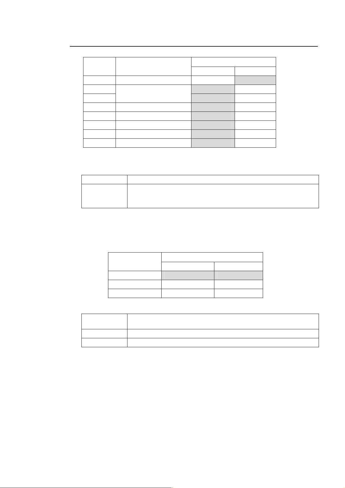
5-1-2. SW2
Dipswitch SW2
Pin No. Function
* Shaded cells indicate factory default.
REMOTE (SW2-1)
DCC-OU Controls DCC-100 from DCC-OU.
DCC-OUA
(Default)
Setting
OFF ON
1 REMOTE DCC-OU DCC-OUA
2 OFF ON
3
4 FACTORY SET ― ―
5 FACTORY SET ― ―
6 FACTORY SET ― ―
7 FACTORY SET ― ―
8 FACTORY SET ― ―
GAMMA MODE
Controls DCC-100 from DCC-OUA.
INPUT SELECT (front panel), SPLIT (front panel) and GAMMA MODE
(dipswitch SW2) must be set not from DCC-100 but from DCC-OUA.
OFF ON
GAMMA MODE (SW2-2, SW2-3)
Select the suitable type of gamma correction from the following three adjustments with two
dipswitches. (When operating with DCC-OUA, change Gamma mode from DCC-OUA.)
GAMMA MODE Setting
SW2-2 SW2-3
CENTER OFF OFF
BLACK ON OFF
WHITE OFF ON
* Shaded cells indicate factory default.
CENTER
(Default)
BLACK Gamma curve is weighted toward Shadows (near 25%)
WHITE Gamma curve is weighted toward Highlights (near 75%).
* Refer to the figures in the next pages.
FACTORY SET (SW2-4, 5, 6, 7, 8)
Factory default setting. Do not change.
Gamma curve is weighted toward the mid tones (near 50%).
11
Page 18
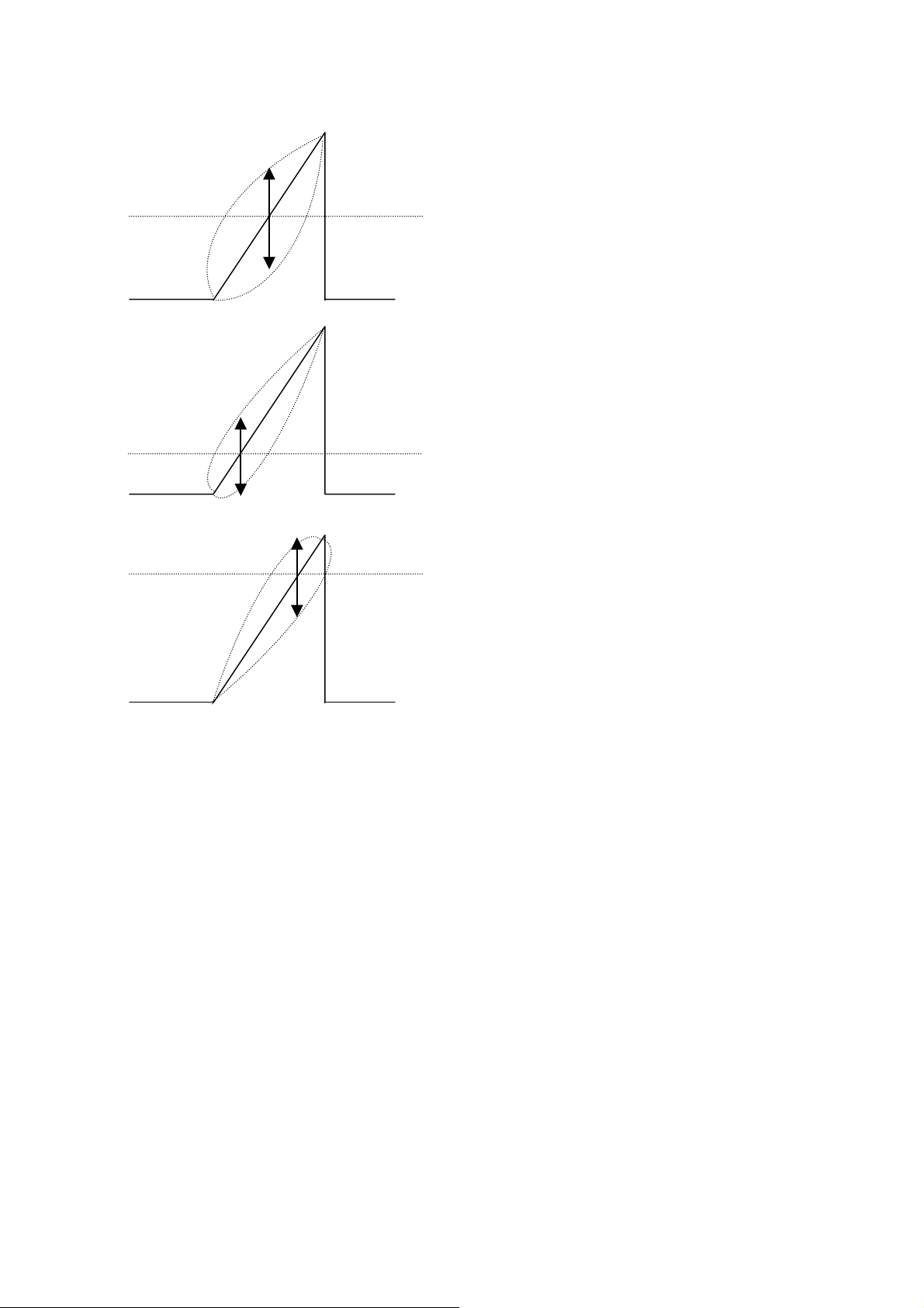
(
)
Gamma Mode
Correction
Range
50%
If Center is selected
default
Correction
Range
25%
If Black is selected
Correction
Range
75% If White is selected
12
Page 19
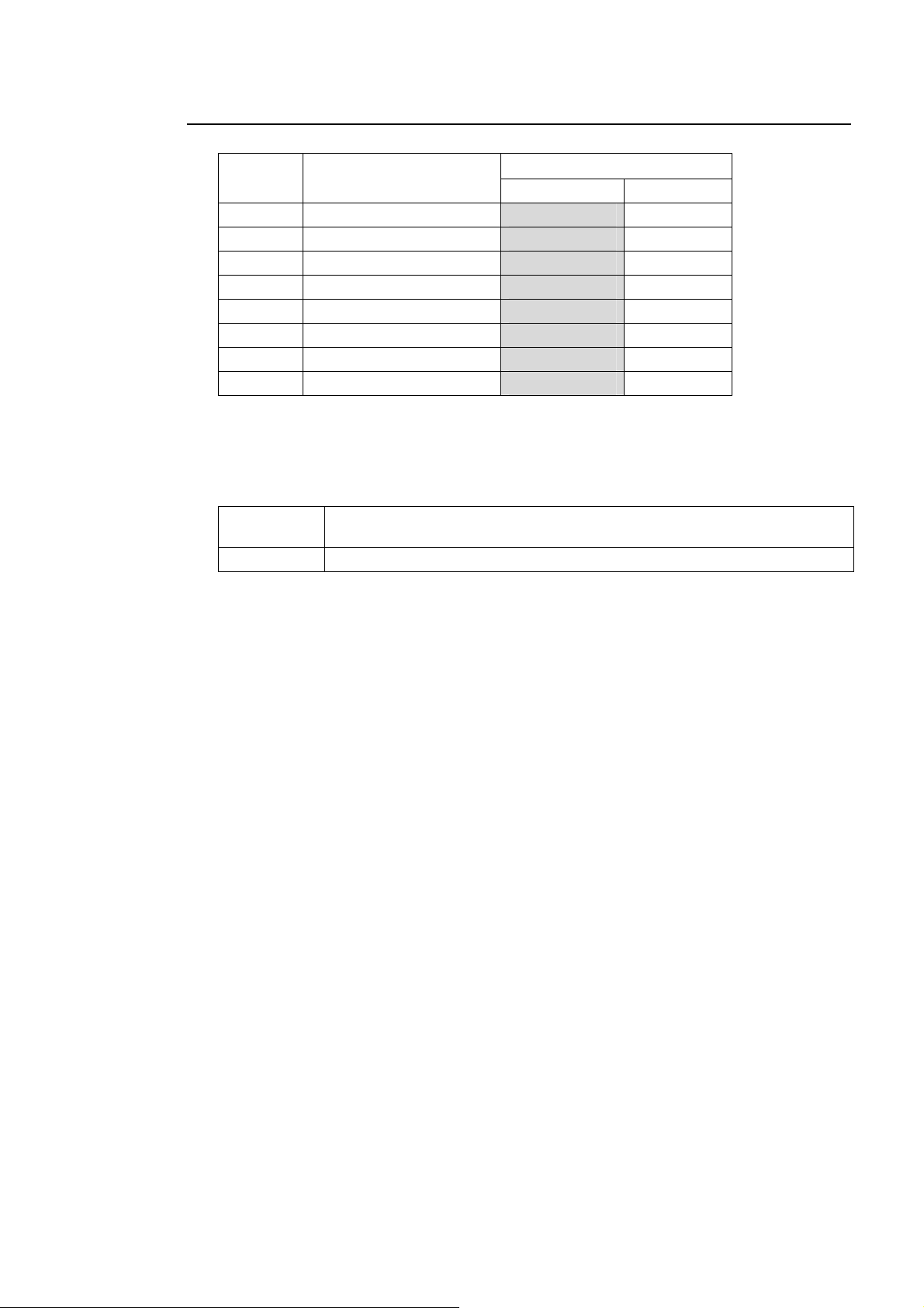
5-1-3. SW3 (SETUP Setting)
Dipswitch SW3
Pin No. Function
1 SETUP OFF ON
2 FACTORY SET ― ―
3 FACTORY SET ― ―
4 FACTORY SET ― ―
5 FACTORY SET ― ―
6 FACTORY SET ― ―
7 FACTORY SET ― ―
8 FACTORY SET ― ―
* Shaded cells indicate factory default.
SET UP (SW3-1)
Selects setup 0 or 7.5. Set to ON when processing NTSC Setup 7.5. (US mode)
OFF
(Default)
ON Processes with 7.5 setup.
Processes with 0 setup.
Setting
OFF ON
FACTORY SET (SW3-2, 3, 4, 5, 6, 7, 8)
Factory default setting. Do not change.
13
Page 20
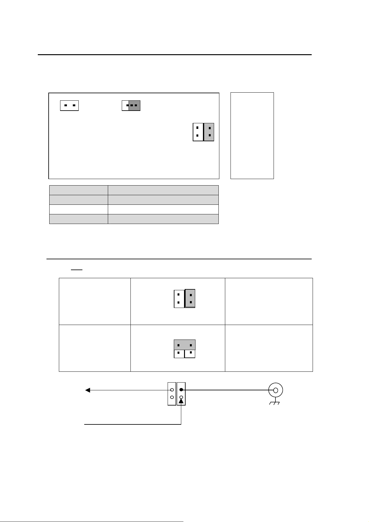
5-2. Jumper Settings
The following settings can be made at the jumpers on MAIN CARD inside the DCC-100.
2 1
JP1
JP NO. Factory Default
JP1 Open
JP2 3-4 short
JP3 1-2 short
* Do not change JP1 and JP3.
5-2-1. COMPOSITE OUT 2 / GENLOCK IN Switching
MAIN CARD
1 3
JP3
Factory Default Settings
1
JP2
I/O CARD
42
3
Jumper JP2 is used to select COMPOSITE OUT 2 or GENLOCK IN.
COMPOSITE OUT 2
(Default)
3-4 short
42
JP2
3
1
GENLOCK IN 2-4 short
42
1
JP2
3
GENLOCK
2
4
1
JP2
COMPOSITE
OUT 2
3
The connector is used as
COMPOSITE OUT 2, which
outputs the processed
composite signal.
The connector is used as
GENLOCK IN, which inputs
a reference signal.
COMPOSITE OUT 2
/ GENLOCK IN
14
Page 21
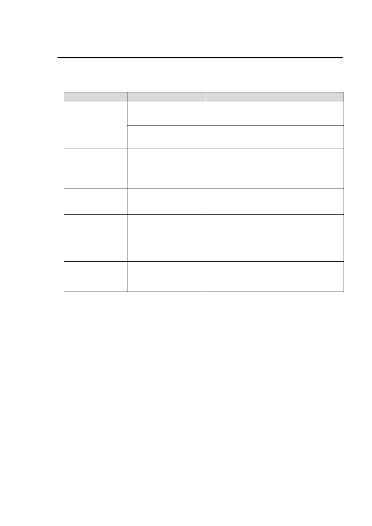
6. If Problems Occur
If any of the following problems occur during operation of your unit, proceed as indicated below to
see if problem can be corrected before assuming a unit malfunction has occurred.
Problem Check Action
If dipswitch SW2-1 is set to DCC-OUA(ON),
Cannot operate
front panel.
Cannot make
GAMMA MODE
setting by
dipswitch.
Input video signal
not bypassed when
powered OFF.
No split screen is
displayed.
No split screen is
displayed despite in
SPLIT mode.
(Composite out)
No split screen is
displayed despite in
SPLIT mode.
(SD-SDI out)
With DCC-OU
With DCC-OUA
With DCC-OU
With DCC-OUA
VIDEO OUT connection
(rear panel)
SPLIT mode setting
(front panel)
SPLIT OFF setting
(dipswitch)
SPLIT OFF setting
(dipswitch)
change to DCC-OU (OFF). See section 5-1-2.
"SW2."
INPUT SELECT and SPLIT cannot be set
from DCC-100 front panel. Set them from
DCC-OUA.
If dipswitch SW2-1 is set to DCC-OUA(ON),
change to DCC-OU (OFF). See section 5-1-2.
"SW2."
GAMMA MODE cannot be set from the
dipswitch on DCC-100. Set it from DCC-OUA.
Only SD-SDI OUT 1 and COMPOSITE OUT 1
have bypass capability.
See section 2-2. "Rear Panel."
If SPLIT switch is set to OFF, change split
mode to 1 or 2. See section 4-2-2. "SPLIT
If SW1-3 is set to SPLIT OFF, change to
SPLIT ON. See section 5-1-1. "SW1."
If SW1-4 is set to SPLIT OFF, change to
SPLIT ON. See section 5-1-1. "SW1."
15
Page 22

7. Specifications & Dimensions
7-1. Unit Specifications
Standard 525/60 (NTSC) , 625/50 (PAL) (Auto detection)
Signal Processing 4:2:2 component
Correction Range 2 field (field inversion prevented)
Sampling Frequency Y: 13.5MHz, C: 6.75MHz
Quantization 10-bit
Video Input
SDI
Analog composite
Video Output
SDI
Analog composite *
Genlock input *
* Select one of them (COMPOSITE OUT 2 or GENLOCK IN) by jumper switching.
Input lock range 1 frame with respect to genlock timing
I/O delay
When composite input is used:
Frequency
PAL 100 kHz to 5.0 MHz: within ±0.5 dB,
S/N Ratio 60dB or higher
DG/DP
K Factor (2T pulse) 1% or less
H/V Tilt 1% or less
Residual Jitter Y: ±15ns C: ±2°
FSC pull-in range -300 Hz to +300 Hz (video input)
Proc Amp (operated from DCC-OU or DCC-OUA)
Video level 0% to 200%
Y level 0% to 200%
Chroma level 0% to 200%
Setup/Black More than ±150mV
Chroma phase
INPUTmode 2H (NTSC composite)
FRAME mode 1 frame (when input video phase is same as genlock signal)
Response
270Mbps, 75Ω, BNC, 1 input
1.0 Vp-p, 75Ω, BNC, 1 input
270Mbps, 75Ω, BNC, 2 outputs
1.0 Vp-p, 75Ω, BNC, 2 outputs
B.B., NTSC: 0.429Vp-p PAL: 0.450Vp-p, 75Ω, BNC, 1 input
3H (PAL composite)
1H (SD-SDI)
NTSC 100 kHz to 4.2 MHz: within ±0.5 dB,
4.2 MH to 5.0 MHz: within ±1 dB,
roll off above 5.0MHz
5.0 MH to 5.5 MHz: within ±1 dB,
roll off above 5.5 MHz
1% / 1
±180 ゚
° (ALP50%)
16
Page 23

Color Correction (operated from DCC-OU or DCC-OUA)
Correction mode Balanced, Differenctial, Sepia
White level (RGB) 50% to150% (based on input signal)
Black level (RGB) 50% to 150% (based on input signal)
Gamma level (RGB) 75 to125% (based on input signal)
Color Gamut Control (operated from DCC-OU or DCC-OUA)
Y White clip 50% to 109%
C White clip 50% to 111%
Y Black clip -7.5% to 50%
Interfaces
Remote (RS-422) 9-pin D-sub, 1port
Temperature
10 ゚ C to 40 ゚ C
Humidity 30 % to 90 % (no condensation)
Power 100VAC to 240VAC ±10% 50/60Hz
Consumption 100V-120V : 22VA (13W)
Dimensions 212 (W) x 44 (D) x 350 (D) mm
Weight 2.5 Kg
Comsumables Cooling fan 109P0405M6D01
(Change every 5 years at normal temprature.)
17
Page 24
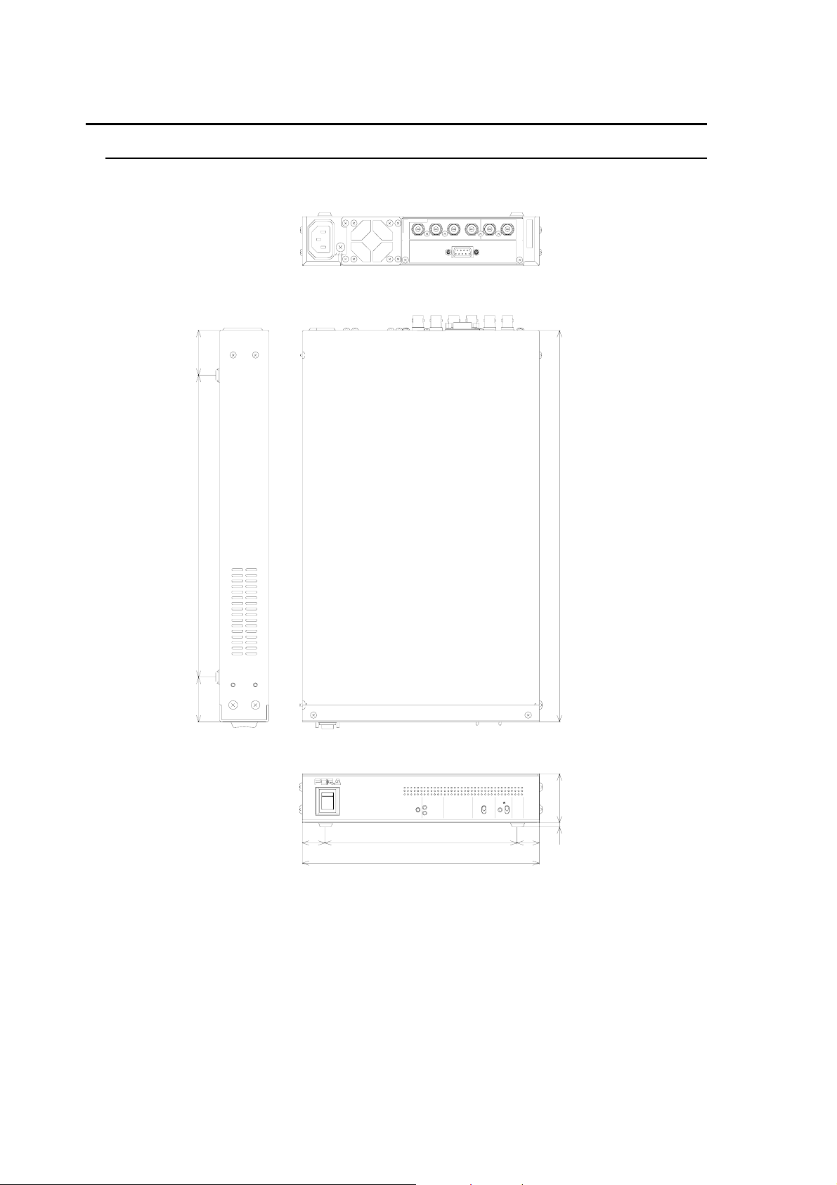
7-2. External Dimensions
7-2-1. Single Unit
All dimensions in mm
UFM-10 0DCC
AC100-240V
50/60Hz IN
OUTPUT
COMPOSITE 2COMP OSITE 1SD-SDI 2SD-SDI 1SD-SDICOMPOSITE
REMOTE
INPUT
SER.NO.
350
40 270 40
DCC-100
COMPOSITE IN
SD-SDI IN
DIGITAL C O LOR CORRECTO R
INPUT SELECT
COMPOSITE
SD-SDI
SPLIT
ON
OFF
3.6 44
ON
ON
OFF
OFF
POWER
20 172 20
POWER
212
18
Page 25
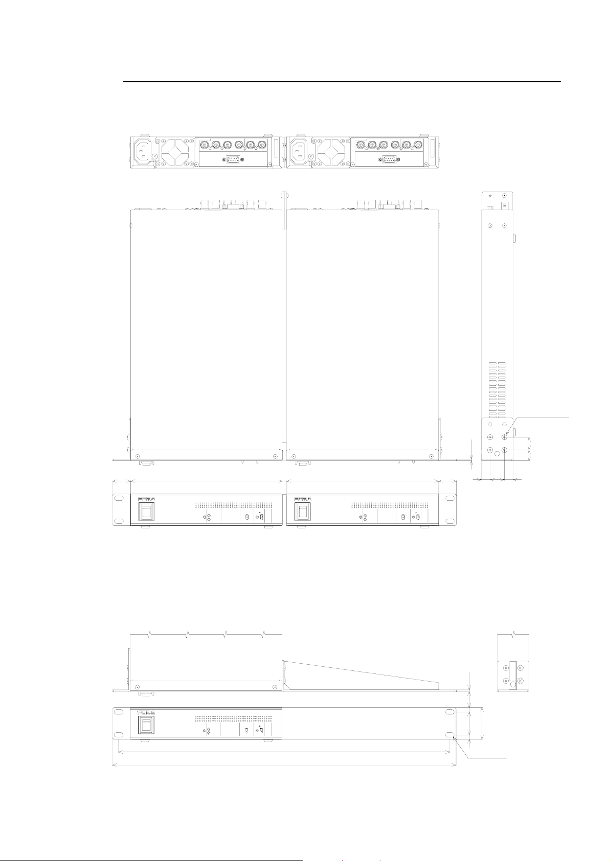
7-2-2. Rack Mounting Examples
Dual unit
AC100-240V
50/6 0Hz I N
UFM -10 0D CC
OUTPU TINPUT
COMPOSI TE 2COMPOSI T E 1SD-SDI 2SD-SDI 1
AC100-240V
SER.NO.
SD-SDICO MPOS ITECOMPOSITE 2COMPOSI TE 1SD-SDI 2SD-SDI 1
REM OT E
50/6 0Hz I N
25 212 6 212 25
ON
ON
OFF
OFF
POWER
COMP OS ITE IN COMP OS ITE IN
POWER
SD- SDI IN
DIGITAL CO L OR CORRECTOR
INPUT SELECT
COMPOSITE
SD-SDI
SPLIT
DCC-100
ON
OFF
ON
ON
OFF
OFF
POWER
UFM-100DCC
OUTPUTINPUT
REMOTE
POWER
SD- SDI IN
DIGITAL COLOR CORRECTOR
INPUT SELECT
COMPOSITE
SD-SDI
All dimensions in mm
SER.NO.
SD-SDICOMPO SITE
M4 BIN D SCREW
L=8
t2.3
12 20 12
DCC-100
SPLIT
ON
OFF
15 18
Single unit
t2.3
DCC-100
ON
ON
OFF
OFF
POWER
COMP OS ITE IN
POWER
SD- SDI IN
DIGITAL COLOR CORRECTOR
INPUT SELECT
COMPOSITE
SD-SDI
SPLIT
ON
OFF
462
480
44
6326
2x2-6.4x2
19
Page 26

Page 27

Warning
This equipment has been tested and found to comply with the limits for a
Class A digital device, pursuant to Part 15 of FCC Rules. These limits are
designed to provide reasonable protection against harmful interference
when the equipment is operated in a commercial environment. This
equipment generates, uses, and can radiate radio frequency energy and,
if not installed and used in accordance with the instruction manual, may
cause harmful interference to radio communications. Operation of this
equipment in a residential area is likely to cause harmful interference, in
which case the user will be required to correct the interference at his own
expense.
Page 28

09/29/2009 Printed in Japan
FOR-A COMPANY LIMITED
Head Office : 3-8-1 Ebisu, Shibuya-ku, Tokyo 150-0013, Japan
Overseas Division Phone: +81 (0)3-3446-3936, Fax: +81 (0)3-3446-1470
Japan Branch Offices : Osaka/Okinawa/Fukuoka/Hiroshima/Nagoya/Sendai/Sapporo
R&D/Production : Sakura Center/Sapporo Center
FOR-A America Corporate Office
11125 Knott Ave., Suite #A, Cypress, CA 90630, USA
Phone: +1 714-894-3311 Fax: +1 714-894-5399
FOR-A America East Coast Office
Two Executive Drive, Suite 670, Fort Lee Executive Park, Fort Lee NJ 07024, USA
Phone: +1 (201) 944-1120 Fax : +1 (201) 944-1132
FOR-A America Distribution & Service Center
2400 N.E. Waldo Road, Gainesville, FL 32609, USA
Phone: +1 352-371-1505 Fax: +1 352-378-5320
FOR-A Corporation of Canada
346A Queen Street West, Toronto, Ontario M5V 2A2, Canada
Phone: +1 416-977-0343 Fax: +1 416-977-0657
FOR-A Latin America & the Caribbean
5200 Blue lagoon Drive,
Suite 760, Miami, FL 33126, USA
Phone: +1-305-931-1700 Fax: +1-305-264-7890
FOR-A UK Limited
UNIT C71, Barwell Business Park, Leatherhead Road, Chessington Surrey, KT9 2NY, UK
Phone: +44 (0)20-8391-7979 Fax: +44 (0)20-8391-7978
FOR-A Italia S.r.l.
Viale Europa 50 20093, Cologno Monzese (MI), Milan, Italy
Phone: +39 02-254-3635/6 Fax: +39 02-254-0477
FOR-A Corporation of Korea
801 Dangsan Bld., 53-1 Dangsan-Dong, Youngdeungpo-Gu, Seoul 150-800, Korea
Phone: +82 (0)2-2637-0761 Fax: +82 (0)2-2637-0760
FOR-A China Limited
708B Huateng Building, No. 302, 3 District, Jinsong, Chaoyang, Beijing 100021, China
Phone: +86 (0)10-8721-6023 Fax: +86 (0)10-8721-6033
*The contents of this manual are subject to change without notice.
 Loading...