

Food Warming Equipment Company ETC-12 Installation Manual
OPERATING
INSTRUCTIONS
ADJUSTABLE UPRIGHTS
Top Pin
Alignment
Holes
(in sets
of pairs)
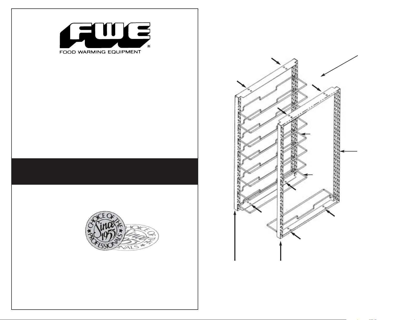
Description of the
ETC Adjustable Upright Assembly
Upright
Assembly
consists of a
left side rack
and a
right side rack
Tray
Slide
Tray Slide
Mounting
Holes
Tray
Slide
(Refer to
Figure 4)
TM
FOR “ETC” SERIES
Food Warming Equipment Company, Inc.
P.O. Box 1001 • Crystal Lake, IL 60039-1001
FWE Parts Department: 815 459 7500
Upright
Assembly
“A”
(holds
left side
tray slides)
Upright
Assembly
“B”
(holds
right side
tray slides)
Bottom Pin
Alignment Holes
(in sets of pairs)
Figure 1: Upright Assembly
with features identified.
ETC Adjustable Upright Assembly
mounts to Top and Bottom Alignment Pins
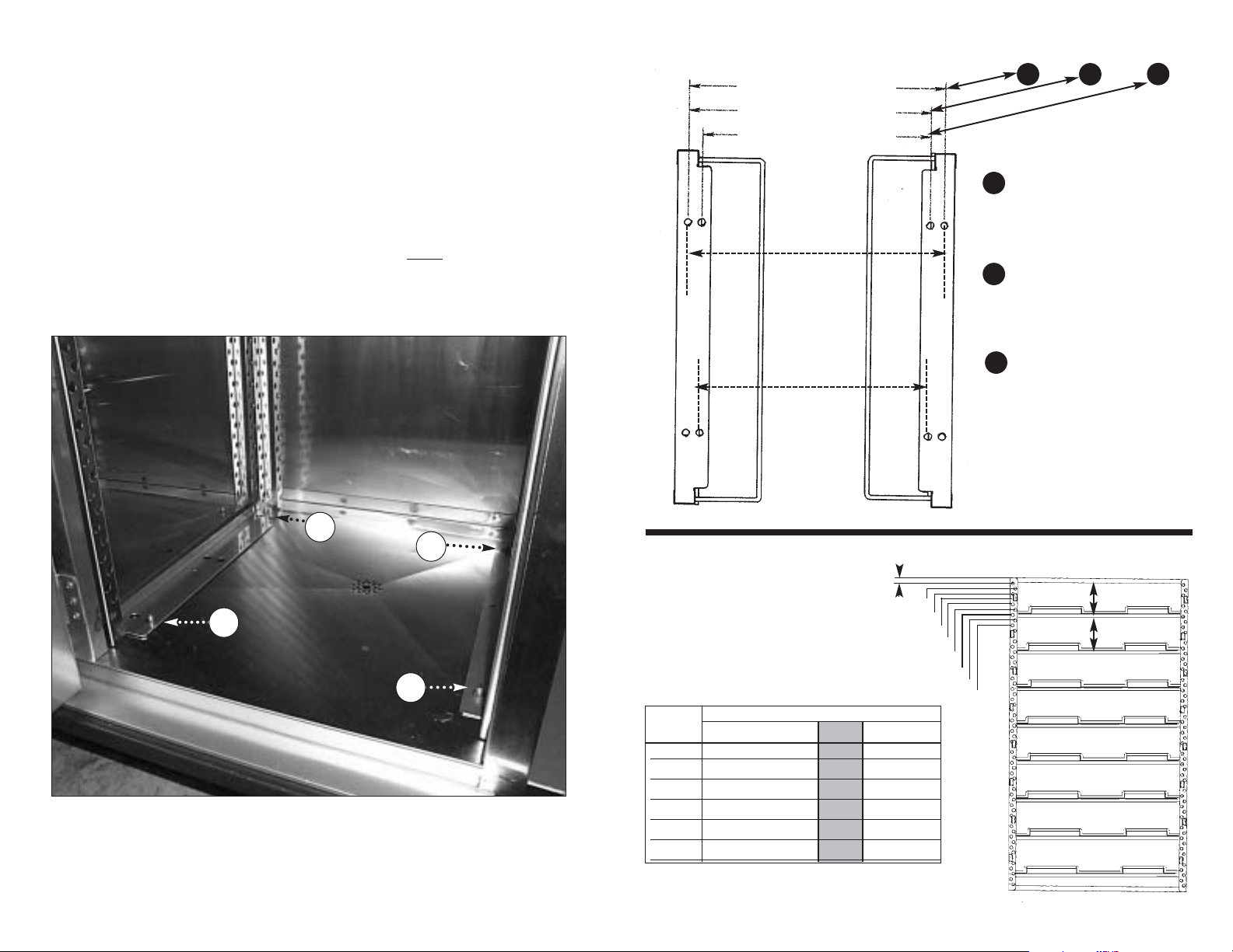
Choosing the Position of your Upright Assembly to fit your tray size:
16” x 22”Trays
1 2 3
15” x 20”Trays
Alignment Pins
are mounted at the inside top panel
and at the inside bottom floor of each compartment, having
four (4)
(Location of the bottom
Position each Upright Assembly to fit y
Alignment Pins
total per each set of uprights.
Alignment Pins
by choosing a set of
is shown in Figure 2.)
our tray size
Alignment Holes
.
(See Figure 3 on the following page for tray sizes and positions.)
A2
B2
Location of the
A1
bottom
Alignment Pins
for Upright
Assembly
B1
Figure 2: Upright Assembly is mounted to cabinet
Alignment Pins,
with the location of the
bottom pins detailed.
14” x 18”Trays
Alignment
Hole
Outward
Position
Alignment
Hole
Inward
Position
Spacing the Tray Slides
to meet your capacities:
Tray Slides can be positioned
at a choice of .75” increments
for greater flexibility.
MODEL
NUMBER
ETC-12 20 16 14
ETC-16 28 22 18
ETC-18 30 24 21
ETC-20 34 28 24
ETC-24 42 33 27
ETC-30 51 42 36
Sets of tray slides are provided for 5.25”spacings
to meet these capacities.
TRAY CAPACITIES AT SPACINGS OF:
3” 3.75” 4.5”
5.25”
12
16
18
20
24
30
6” 6.75”
10 10
14 12
15 15
18 16
21 18
27 24
1
2
3
Figure 3: Place uprights to meet
your tray size by positioning the
outward or inward
upon the
.75” INCREMENTS
1.5”
2.25”
3.0”
3.75”
4.5”
5.25”
6.0”
6.75”
Both uprights located
in outward position.
One upright in
outward position,
one upright in
inward position.
Both uprights located
in inward position.
Alignment Holes
Alignment Pins.
5.25” Spacing
5.25” Spacing
Figure 4: Side View of ETC-16.
 Loading...