

Page 1

CONVERSION VIDEO SHOULD BE
WATCHED BEFORE PERFORMING
CONVERSION TO NATURAL GAS
****All conversions must be performed by a
certified gas technician****
Video can be found on
WWW.FONTANAFORNIUSA.COM
For any further questions call
877-842-9822
****IMPORTANT****
Read First
Page 2
1
Item
Description
#
Required
1
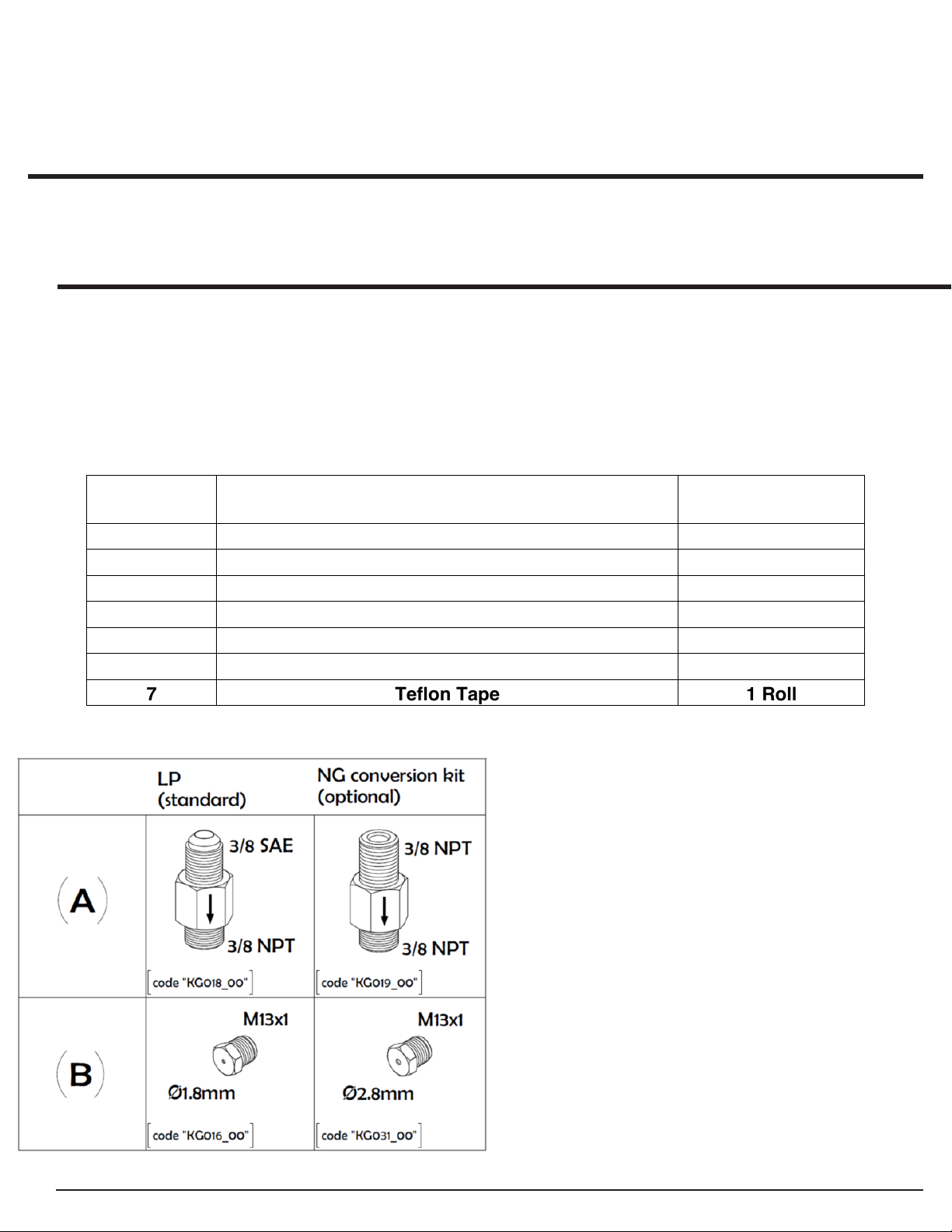
2.80mm Orifice
1
2
Fixed Regulator
1
3
3/8” Male-Male NPT Fitting
1
4
Female-Female Quick Disconnect Fitting
1
5
10' Flexible Hose
1
6
3/8" SAE x 3/8" NPT Adapter
1
7
Teflon Tape
1 Roll
Fontana Forni USA:
GAS SMOKER OVEN
Margherita & Mangiafuoco Model
NATURAL GAS CONVERSION KIT
(Part No. FTNGK)
For FTMARG & FTMFG Models
All gas connections must be made by a competent qualified service technician and in accordance with local codes and
ordinances. In the absence of local codes, the installation must comply with the National Fuel Gas Code (NFPA 54/ANSI
Z223.1).
Before beginning conversion, make sure all parts are present. Compare parts with package contents. If any part is
missing or damaged, do not attempt to convert. Contact your appliance dealer for replacement parts.
PARTS LIST:
The following parts are included in the “Natural Gas Conversion Kit” and are not included with the appliance.
Two adjustable wrenches (not included) will be needed to convert the appliance from LP to NG.
Page 3
2
WARNING
MONOXIDE HAZARD
If the information in these instructions is not
loss of life.
This conversion kit shall be installed by a
supplied with the kit.
ATTENTION
RISQUE DE MONOXYDE DE CARBONE
Si les informations contenues dans ces
dommages à la propriété des dommages, des
blessures ou des pertes de vie.
Ce kit de conversion doit être installé par un
esponsable de l'installation correcte de ce kit.
vérifié comme spécifié dans le instructions du
fabricant fournies avec trousse.
FIRE, EXPLOSION, AND CARBON-
INCENDIE, EXPLOSION ET
followed exactly, a fire, explosion, or
production of carbon monoxide may result
causing property damage, personal injury, or
instructions ne sont pas suivi exactement, un
incendie, une explosion ou une production
de monoxyde de carbone peut entraîner des
qualified agency in accordance with the
appliance manufacturer's instructions and all
applicable codes and requirements of the
Authority Having Jurisdiction. The qualified
agency is responsible for the proper
installation of this kit. The installation is not
proper and complete until the operation of
the converted appliance is checked as
specified in the manufacturer's instructions
agence qualifiée conformément à
instructions du fabricant de l'appareil et tous
codes applicables et exigences de Autorité
ayant compétence. Le qualifié l'agence est
L'installation n'est pas correcte et compléter
jusqu'à l'opération du converti appareil est
Page 4
3
NATURAL GAS CONVERSION
!
PREPARATION FOR NG CONVERSION:
1. Turn off gas supply, and then remove cap on gas supply line.
2. REQUIRED: An authorized technician must install a gas shutoff valve easily accessible to the appliance in
accordance with the local codes. In the absence of local codes, the installation must comply with the National
Fuel Gas Code (NFPA 54/ANSI Z223.1).
3. Converting your Fontana Forni USA: Gas Smoker Oven is best done with the support legs installed. Then,
remove the support legs after conversion is completed if desired for final installation.
NATURAL GAS CONVERSION:
WARNING: Before the conversion, make sure control knob is in the OFF position, propane (LP) tank valve is
closed, and the tank is disconnected from regulator and removed to a safe place away from the appliance.
Ensure the appliance is secured before working on it.
NG Input Rate: 36,000 BTU/hr.
ORIFICE:
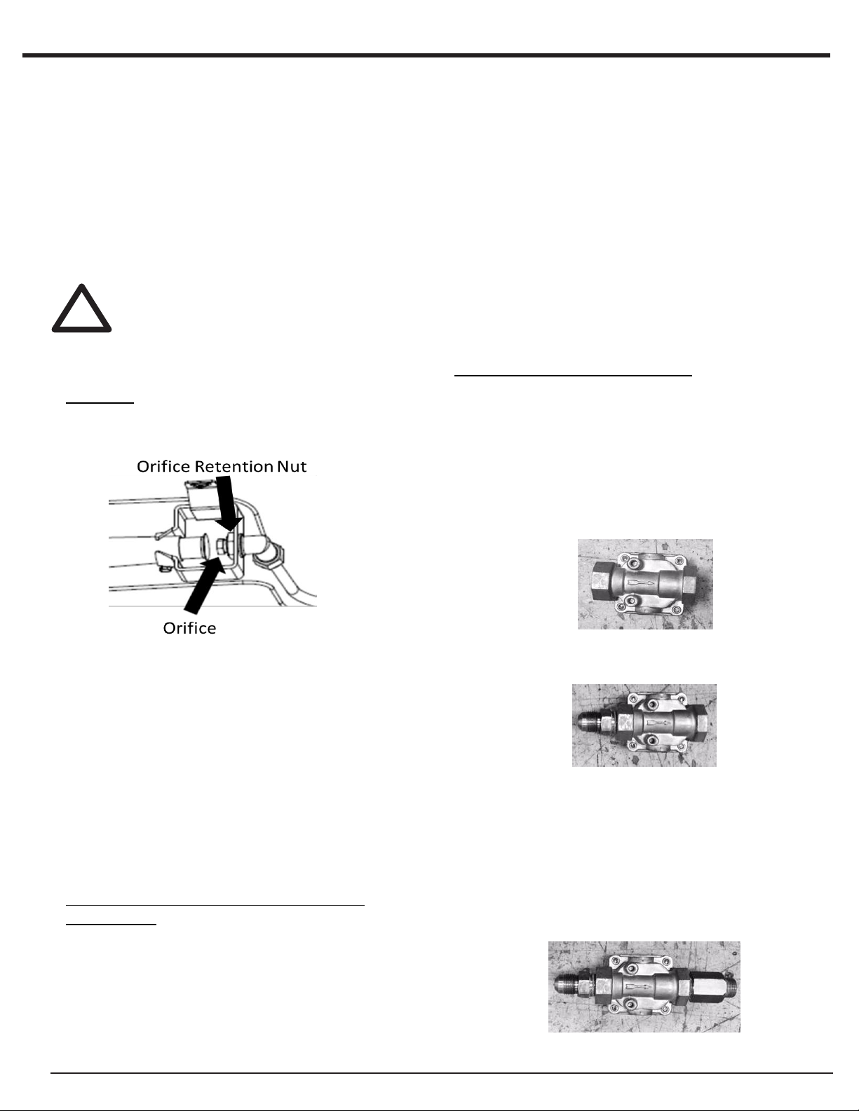
1. Locate the LP orifice (1.75mm) on the
underside of the unit.
INSTALLING NG REGULATOR:
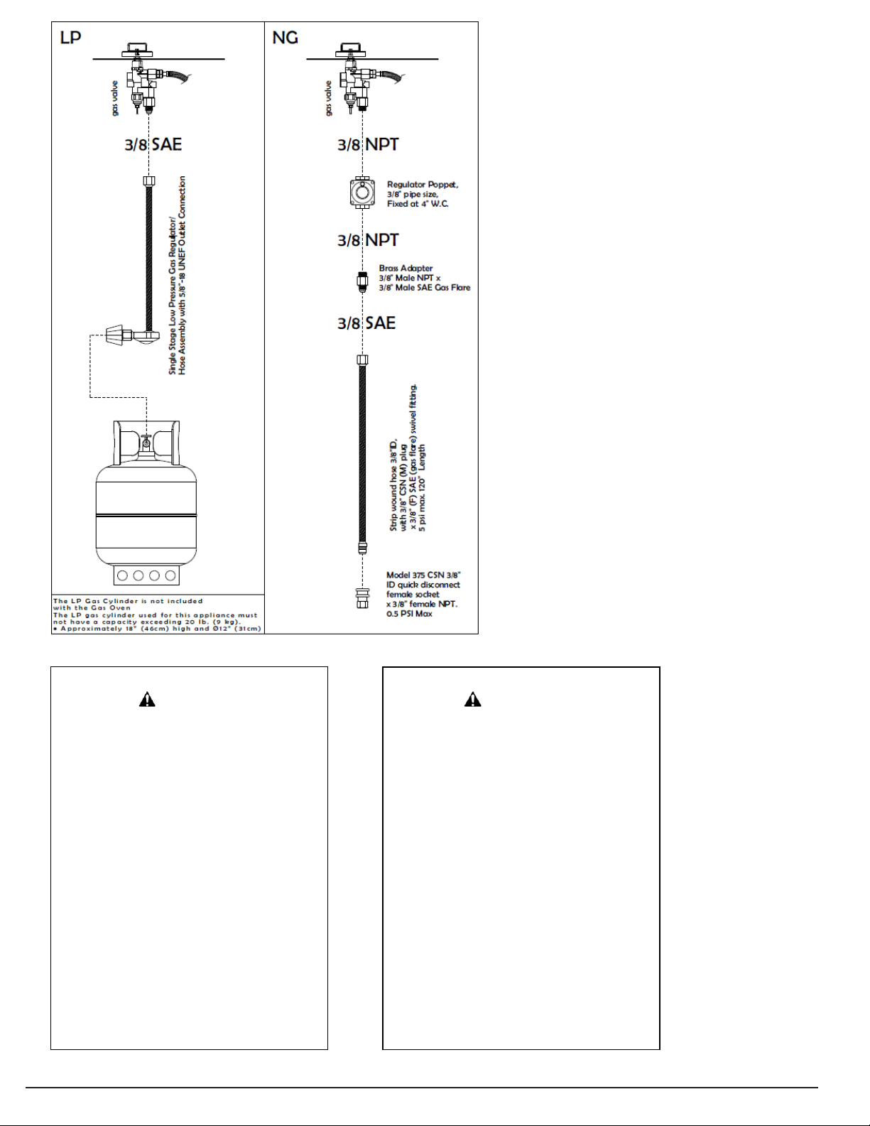
1. Locate the NG fixed regulator, Teflon tape, 3/8"-24 x
3/8" NPT adapter, and 3/8” male flare fitting supplied
in the conversion kit.
2. Apply Teflon tape per manufacturer’s instructions to
the NPT thread of the male flare fitting.
3. Flip the NG regulator over and examine the regulator
for a gas flow direction arrow. The side where the
arrow terminates is the outlet of the gas regulator.
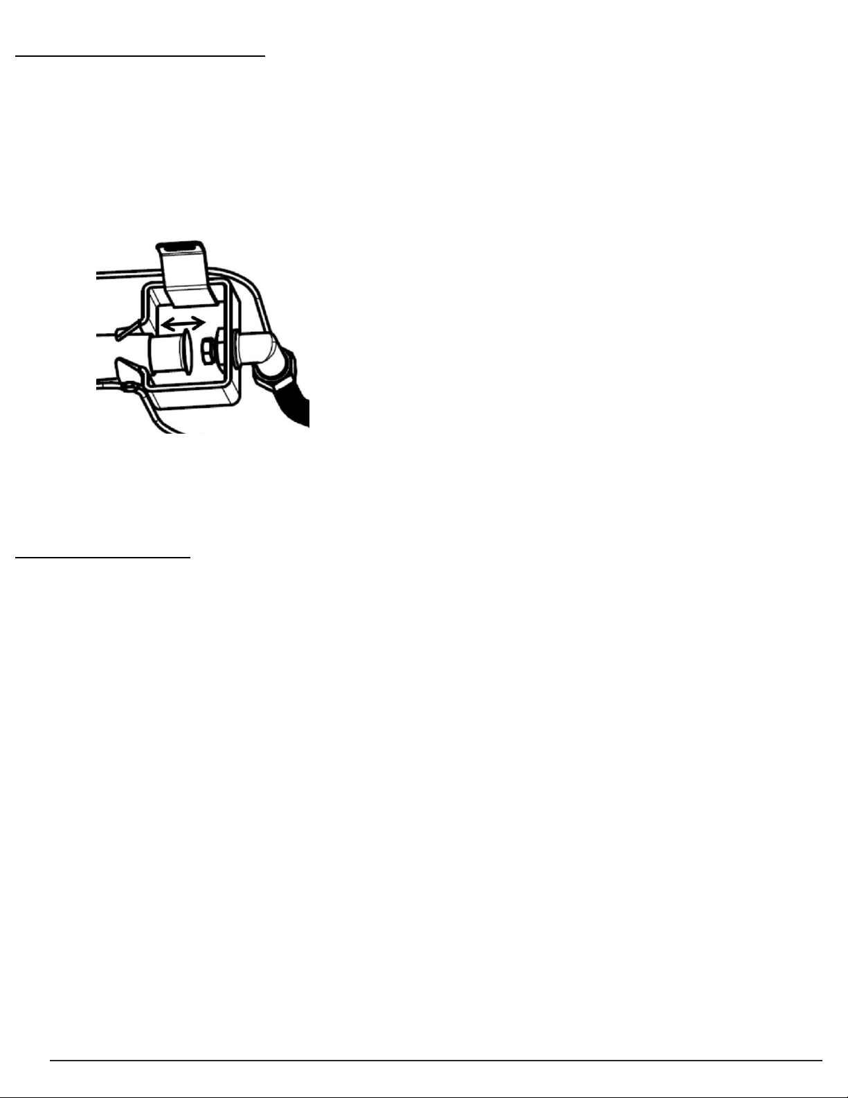
2. Remove the LP orifice by using an
adjustable wrench to turn the orifice counterclockwise. Ensure to use a backup
adjustable wrench on the orifice retention nut
while un-tightening the LP orifice.
3. Locate the natural gas (NG) orifice (2.80mm)
inside the conversion kit.
4. Thread the NG orifice by hand into the orifice
holder until it is hand tight.
5. Use an adjustable wrench to tighten the NG
orifice. Ensure to use a backup adjustable
wrench on the orifice retention nut while
tightening.
REMOVING LP REGULATOR & HOSE
ASSEMBLY:
1. Locate the LP regulator and hose assembly
underneath the unit.
2. Follow the hose towards the gas valve to
locate the gas fitting connecting the two.
3. Using an adjustable wrench, untighten the
gas fitting while backing up the gas valve
with a second adjustable wrench.
4. Hand thread the non-flared end of the 3/8” male flare
fitting, with Teflon tape applied, into the inlet of the
gas regulator until hand tight.
5. Using an adjustable wrench, finish tightening the 3/8”
flare fitting into the gas regulator. Ensure to use a
second adjustable wrench to back up the gas
regulator.
6. Apply Teflon tape per manufacturer’s instructions to
the open threads on the 3/8"-24 x 3/8" NPT adapter.
7. Using an adjustable wrench, finish tightening the
3/8"-24 x 3/8" NPT adapter into the regulator. Ensure
to use a second adjustable wrench to back up the
gas regulator.
8. Apply Teflon tape per manufacturer’s instructions to
Page 5
4
the open threads on the 3/8"-24 x 3/8" NPT adapter.
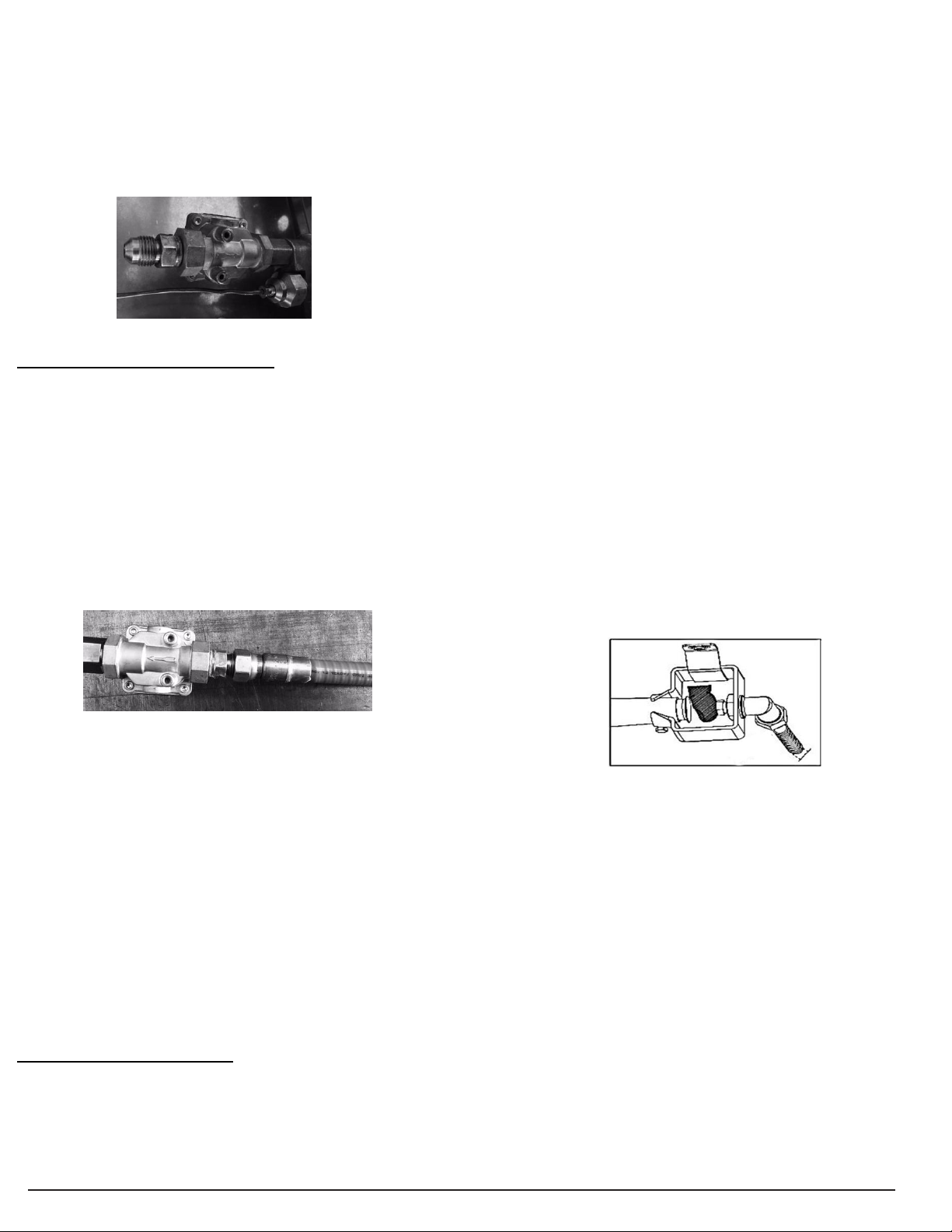
9. Locate the open end of the gas valve underneath the
unit.
10. Hand thread the regulator into the open end of the
gas valve until hand tight. Ensure that the arrow
terminates towards the direction of the valve.
11. Using an adjustable wrench, finish tightening the
regulator into the gas valve. Ensure to back up the
gas valve with a second adjustable wrench.
INSTALLING NG FLEX HOSE:
1. Locate the 10’ flex hose and with quick
disconnection supplied in the conversion kit. Teflon
tape will not be required for this connection.
2. Locate the exposed flare fitting of the NG regulator
underneath the unit.
3. Hand thread the female flare fitting side of 10’ flex
hose side onto the exposed male flare fitting.
4. Using an adjustable wrench, finish tightening the
female flare fitting onto the male flare fitting. Ensure
to use a second adjustable wrench to back up the
male flare fitting.
Do not smoke at any time while testing.
Never test for leaks with a lit match or open flame.
Test for leaks outdoors.
If a leak persists, contact your gas appliance dealer
for assistance. Do not attempt to operate appliance if
a leak is present.
NATURAL GAS PRESSURE AND ADJUSTMENT
Refer to the data plate located on the oven for the
manifold pressure required for Natural Gas (NG)
The Natural Gas regulator is set by the manufacturer
and is not to be adjusted.
TO TEST FOR LEAKS BETWEEN THE NATURAL GAS
SUPPLY AND GAS VALVE:
1. Extinguish any open flame or cigarettes in the area.
2. Be sure gas supply and appliance valves are “OFF.”
3. Prepare a soap solution of one part water, one part
liquid detergent.
4. Brush the soap solution on each connection.
5. Slowly open the natural gas supply valve.
6. A leak is identified by a flow of bubbles from the area
of the leak.
7. If a leak is detected, close the natural gas supply
valve, tighten the connection and retest.
TO TEST FOR LEAKS BETWEEN THE ORIFICE AND
GAS VALVE:
1. Follow steps 1 - 5 from the previous section.
2. Place fingertip over the opening in the orifice.
5. Locate the NG supply with gas shutoff valve already
installed by an authorized technician. CONTACT A
LICENSED PLUMBING CONTRACTOR TO
PERFORM THIS CONNECTION.
6. Apply Teflon tape per manufacturer’s instructions to
the exposed threads of the gas shutoff valve.
7. Hand thread the female NPT quick disconnect fitting
on the exposed threads of the gas shutoff valve until
hand tight.
8. Using an adjustable wrench, finish tightening the
female quick disconnect fitting onto the gas shutoff
valve. ENSURE TO BACK UP THE GAS SHUTOFF
VALVE.
9. Take the male quick connection of the 10’ flex hose
and install it into the female quick connection located
on the gas shutoff valve.
PERFORM LEAK CHECK:
AS A SAFETY PRECAUTION:
Test all fittings for leaks before using your appliance.
Test for leaks every time you connect/re-connect a
gas fitting or line.
3. Turn and hold burner control knob at “HIGH.”
4. A leak is identified by a flow of bubbles from the area
of the leak.
5. If a leak is detected, turn burner control knob to
“OFF”, tighten the connection and retest.
6. When finished, return burner control knob to “OFF”.
IF THE GAS SUPPLY SYSTEM IS PRESSURE
TESTED:
1. The appliance and its individual shutoff valve must
be disconnected from the gas supply piping system
during any pressure testing of that system at test
pressures in excess of ½ psi (3.5 kPa).
2. The appliance must be isolated from the gas supply
piping system by closing its individual manual shutoff
valve during any pressure testing of the gas supply
piping system at test pressures equal to or less than
½ psi (3.5 kPa).
3. The Inlet gas pressure should be between 6.0” – 8.0“
w.c.
Page 6
5
FLAME CHECK & ADJUSTMENT:
1. After performing a leak check, follow the lighting
instructions on the grill to light the burner on “HIGH”.
Note: Air could still be present in gas line after
converting to NG. It might take multiple attempts to
light.
2. All burner ports should show a 4 ½” (11.43cm) flame
on “HIGH”. If flames are lazy yellow or lifting off
burner, adjust air shutter until the flames are mostly
blue and are not lifting.
3. After the flames on “HIGH” have been adjusted if
needed, turn the gas valve to the “LOW”. The flames
at the “LOW” setting should be 1 ½” (3.81cm). If not,
adjust the “minimum flow screw” on the gas valve
until the flames are 1 ½” (3.81cm).
AFTER CONVERSION:
Once the gas smoker oven has been converted to
Natural Gas it is the responsibility of the individual or
agency performing the conversion too mark the data
plate with the below information.
Date (day-month- year) of the conversion
The gas the oven is being converted to
Name and address of organization making this
conversion
All markings should be done in permanent marker and
legible.
Congratulations! Your Fontana Forni USA gas smoker
oven is now converted to be used with NG. Please see
your owner’s manual for proper operation and
maintenance.
 Loading...