

FONESTAR PDA-207 Instruction Manual
PDA-207
LOUDSPEAKER PROCESSOR
2 INPUTS AND 6 OUTPUTS
INSTRUCTION MANUAL

- 2-
We take this opportunity to thank you for buying this product.
We recommend you read the instruction manual before switching on the machine and follow the instructions
that are given. Keep the manual for future reference.
SECURITY AND THE ENVIRONMENT
ELECTRICAL SECURITY
Check that the current in the mains connection where the machine is to be installed corresponds to the
power supply of the machine.
To avoid damaging the equipment, electrical shocks, fire or physical injury when you connect or disconnect
the equipment from the power supply, pull the plug firmly out of the mains socket holding the plug, never the
cable.
Always do this with dry hands.
Keep the power supply cable far from sources of heat. Do not put heavy objects on top of it or change it.
Clean dust and dirt off the power supply cable regularly.
Do not open the machine; you could get an electric shock.
CAUTION
While installing the machine, make sure it is switched off and unplugged.
Do not open the machine. Touching the internal parts is dangerous and you could receive an electric shock.
The machine must not be splashed or dripped on. Never place recipients with liquid inside on the machine.
Do not place anything inside the machine.
LOCATION
Place the equipment on a horizontal surface with enough space around it to allow ventilation.
Avoid direct sunlight, heat sources and excessive dust.
Do not place the machine near magnetic fields or static electricity.
Do not use surfaces which vibrate or receive impact.
Do not pile machines on top of one another.
VENTILATION
Never block or cover the ventilation slits on the machine.
Do not expose it to direct sunlight or place it near sources of heat.
PERIODS OF INACTIVITY
When the machine is not going to be used for a long period of time, disconnect it from the mains.
If you are using an adapter, take into account that it will continue using electricity even if the machine is
switched off. If it is not going to be used for a long period of time, disconnect it from the mains.
THE ENVIRONMENT
To save energy, switch the machine off when you are not going to use it for a long time. The machine could
contain substances that are harmful to the environment or human health. To minimize the effect of these
substances the machine must be correctly managed and recycled when you decide to dispose of it.
When you dispose of it remember: it cannot be thrown into a conventional rubbish bin.
If it contains or uses batteries, these must be disposed of separately.
The machine (without batteries) must be disposed of correctly. Put it in a container specially intended for the
collection of electronic and electrical appliances, at the dump or hand it over to the dealer when you purchase
similar equipment, so that the dealer can dispose of it correctly (at no added cost).
EN
- 3-
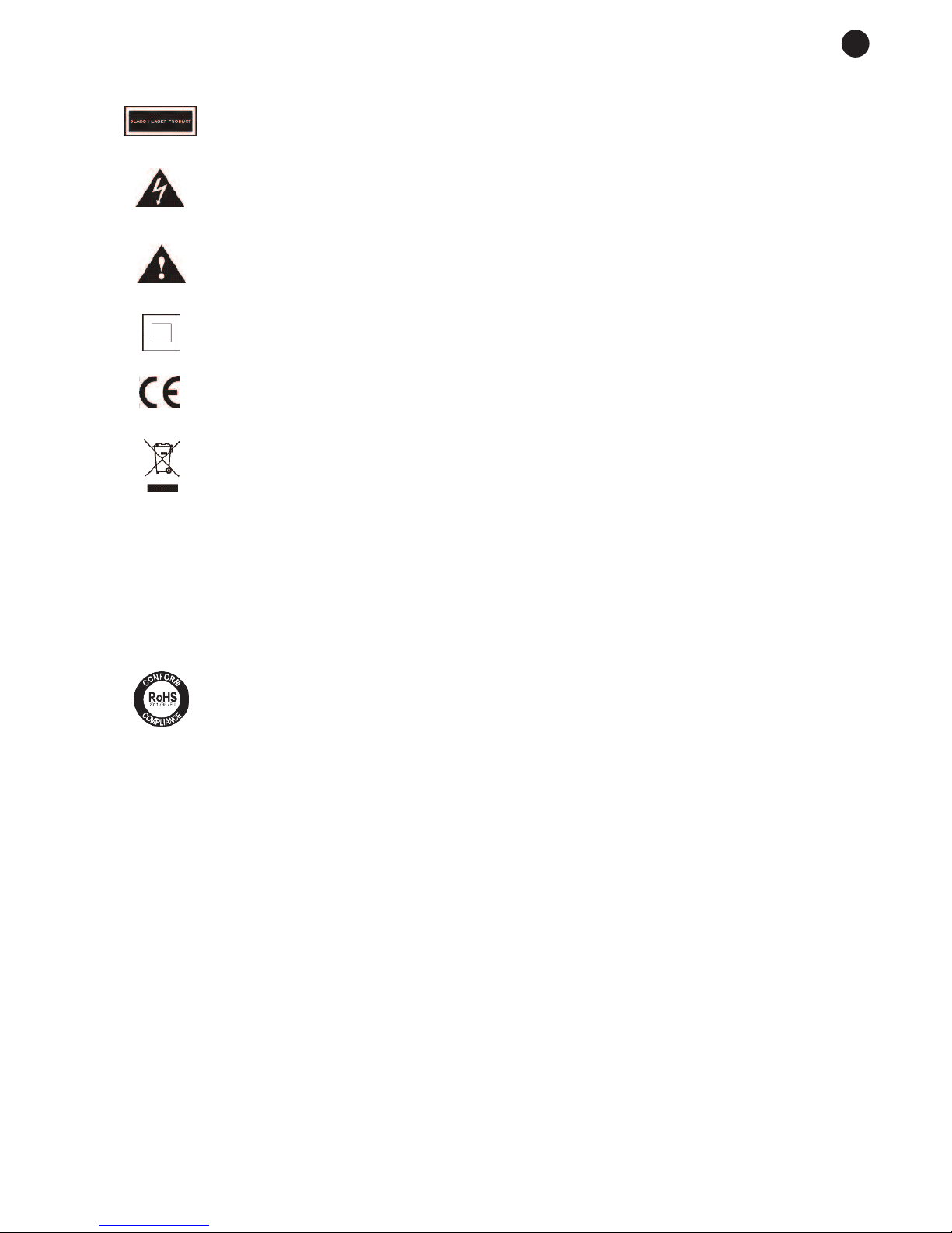
SIGNIFICANCE OF THE SYMBOLS ON THE MACHINE*
The symbol formed by the expression “Class 1 laser product” written in a rectangle
indicates that visible or invisible laser radiation could be produced. Avoid direct exposure
to the laser.
The symbol formed by a ray of lightening inside a triangle shows that the machine has
connection terminals or a circuit with areas with a current which could cause an electric
shock, even in normal working conditions.
The symbol formed by an exclamation mark in a triangle shows that the instruction manual
must be referred to for information on how the machine works and its use.
The symbol formed by one square inside another square shows that the machine has
double electrical insulation.
The European Community symbol shows that the machine complies with the current
European Union legislation, as well as its transposition to local legislation.
The symbol of a rubbish bin crossed out and over a horizontal line shows that when the
product is disposed of it must be done properly, placing it in a special selective electronic
and electrical equipment container or through a dealer when purchasing a similar product,
at no additional cost. It also shows that the machine was put on the market after 13th
August 2005 (European Community Directive 2002/96/CE of Electrical and Electronic
recycling, and its Spanish equivalent R.D.208/2005).
In accordance with what is set out in the aforementioned decree, FONESTAR is registered
in the RAEE (Registro de Aparatos Eléctricos y Electrónicos) in a special section REI
(Registro de establecimientos Industriales), with the entry number 001851.
The symbol RoHS (Restriction of Hazardous Substances) shows that the product has been
designed and manufactured restricting the use of certain dangerous material(Directive
2011/65/EU on the restriction of certain dangerous substances in electrical and electronic
appliances, and its transferal to the Spanish regulations, R.D. 219/2013).
*It is possible that some of these symbols do not appear on the machine.
EXEMPTION OF LIABILITY
The characteristics of the equipment and the content of the manual can change without forewarning.
FONESTAR, S.A. does not assume responsibilities regarding the inappropriate use of the equipment or the
information supplied in this instruction manual, and specifically disclaims any implied liability for marketability
or fitness for any other use.
All rights reserved by FONESTAR, S.A.
EN
DESCRIPTION
Loudspeaker processor with 2 inputs and 6 outputs designed to process and adapt the audio signal to the
characteristics of the P.A. system speakers offering an independent signal in each output. It incorporates
equalization, frequency divider, gain control, limiter, delay and mute functions.
CONTROLS AND FUNCTIONS
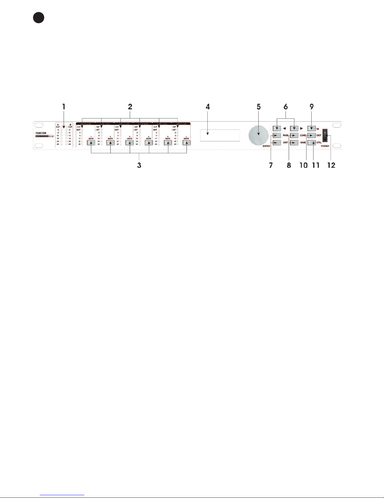
FRONT PANEL
1.- CLIP and input level meters: LED indicators for the signal level in inputs A and B. The CLIP LED lights
up when the input signal is very high and produces distortion. If the CLIP LED indicator lights up, reduce
the input signal level.
2.- Output level meters, CLIP and LIMIT: LED signal level indicators in each output. The LED LIMIT
indicator stays on when the output level limiter is activated. In this case, you must reduce the output
signal level.
3.- MUTE: for silencing the signal level from each output individually. Each of the buttons has an LED
indicator which stays on if MUTE has been activated.
4.- PARAMETER DISPLAY: for viewing the configuration parameters.
5.- ENTER: control wheel used for selecting the desired configuration and modifying the value of the
parameter bieng set.
6.-
a
(Previous), d(Following): for changing option and/or parameter.
7.- PASS-EXIT: the PASS button is used for putting the system in bypass, in other words, the outputs willl
not be affected by any of the equipment configurations. The exit button lets you return to the previous
option.
8.- LOAD, SAVE: for loading or saving user configurations. Up to 80 settings can be saved (10 default and
70 user settings).
9.- IN: for accessing the configuration menu for inputs A and B. See Instructions for use.
10.- OUT: for accessing the output configuration menu. See Instructions for use.
11.- UTIL: for setting different functions on the device. See Instructions for use.
12.- POWER: on/off switch.
- 4-
EN
EN
- 5-
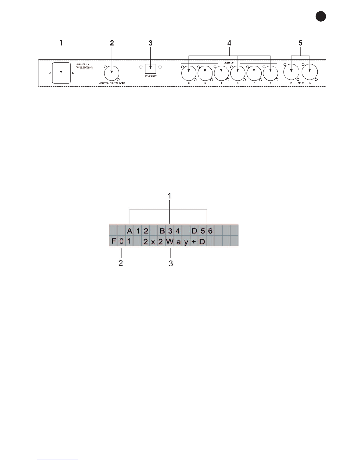
BACK PANEL
1.- AC INPUT: for connecting AC power supply cable.
2.- AES/EBU DIGITAL INPUT: digital AES/EBU type input, XLR connector.
3.- ETHERNET: port for connecting to a computer, RJ-45 connector.
4.- OUTPUTS 1-6: channel output connectors, XLR connector.
5.- INPUTS A-B: channel A and B input connectors, XLR connector.
INSTRUCTIONS FOR USE
GENERAL INFORMATION
When you switch the equipment on, the current configuration is shown on the display:
1.- Inputs and outputs: it shows which input comes from each output. Each letter means the following:
- A: input A.
- B: input B.
- D (Delay): total output of inputs A and B that have had some delay applied to them (See SUM 2 in
the block diagram).
- P (Parametric): total output of inputs A and B that have had some equalization applied to them (See
SUM 1 in the block diagram).
- Numbers 1, 2, 3, 4, 5 and 6 show the outputs.
In the example in the diagram, The signal connected to input A is assigned to outputs 1 and 2; the signal
connected to input B is assigned to outputs 3 and 4 and these inputs would be assigned to outputs 5
and 6 after having a determined delay applied to them (See block diagram).
2.- Configuration type and number: 10 base configurations are included (starting with the letter F, F00 to
F09) and there are 70 editable configurations available for the user (starting with the letter U, U00 to
U69).
3.- Name of current setting: name of configuration in use.
INPUT CONFIGURATION
The different input process functions can be set: GAIN, EQ, DELAY.
To access the configuration menus press the IN button and choose the different process functions with the
(
a
, d) selection buttons.
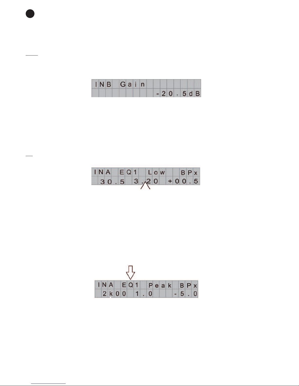
G
AIN
For adjusting the signal level in each input individually.
Note: as the gain is adjusted digitally, the user can select the desired input level, but has to be careful and
not select too high a volume and saturate the signal.
To set the input gain, follow the instructions below:
- Press the IN button and using the selection buttons (
a
, d) choose the GAIN option from the menu (INA
Gain or INB Gain will appear on the display)
- Press the IN button again to change between input A and input B.
- Turn the ENTER control wheel to increase or reduce the gain level, values between -40 dB to 12 dB can
be chosen.
- Press EXIT to exit.
EQ
8-filter parametric equalizer with 1/32 Oct. For equalizing the input signal.
To set the parametric filters, follow the instructions below:
- Press the IN button and using the selection buttons (
a
, d) choose the EQ option from the menu (INA EQx
or INB EQx will appear on the display).
- Press the IN button again to change between input A and input B.
- Press ENTER.
- Turn the ENTER control wheel to modify a parameter and the selection buttons (
a
, d) to change the
parameter.
The configuration parameters are the following:
- Filter selection (EQ1 to EQ8).
For selecting each one of the 8 parametric filters available for each one of the inputs:
- 6-
EN
-
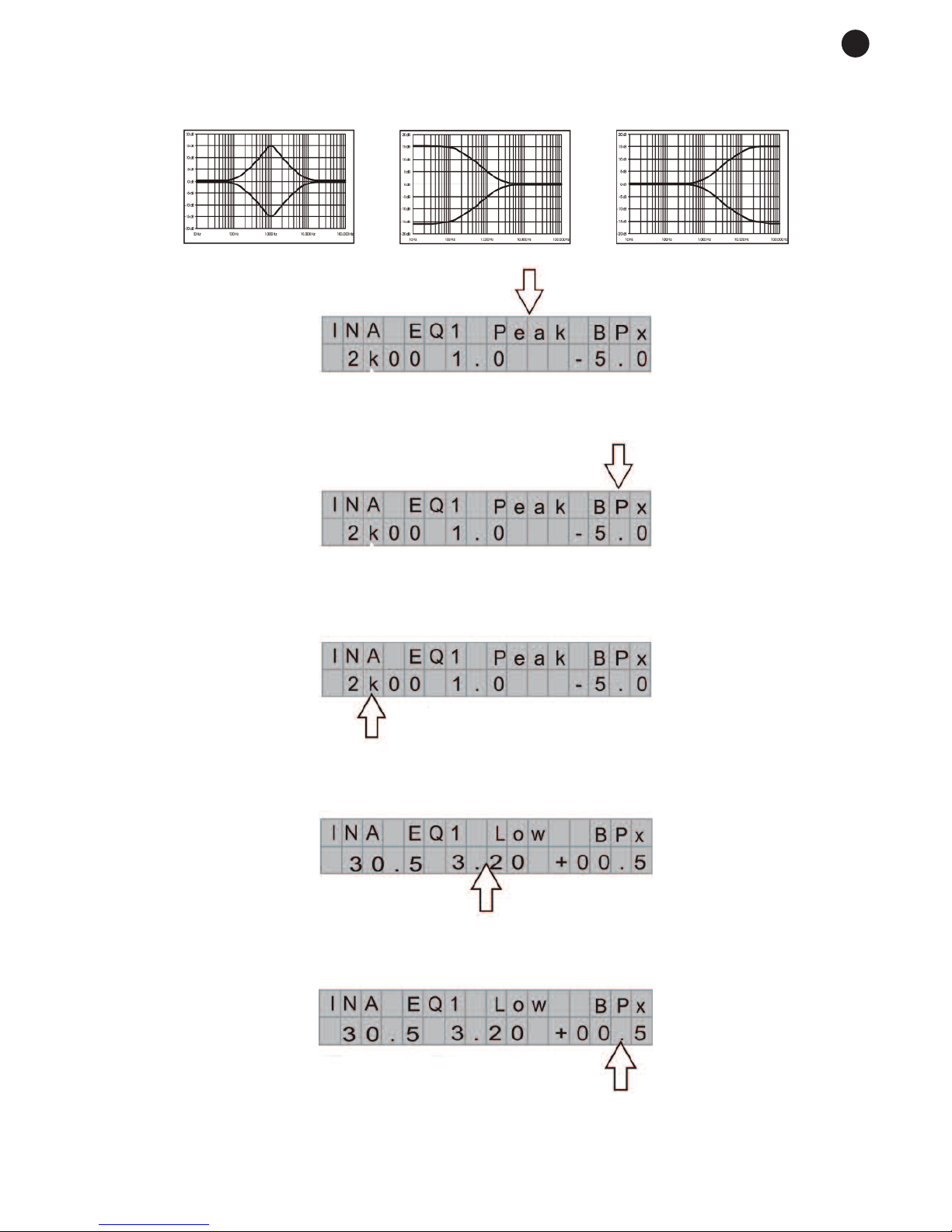
Filter types (PEAK, LOW SH, HIGH SH).
For selecting the filter type to be applied:
Peaking Low shelving High shelving
- Bypass.
For deactivating the chosen filter.
- Central frequency/ cutoff frequency (Hz).
For choosing the central frequency of the peaking filter or the cut off frequency of the high pass or low pass
filters.
- Bandwidth (Hz).
For choosing the bandwidth of the peaking filter in octaves.
- Gain (dB).
For controlling the filter attenuation or gain.
- 7-
EN
 Loading...