

Page 1
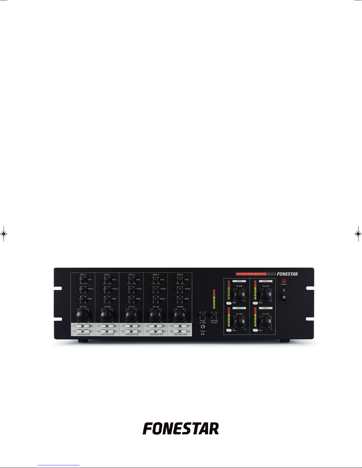
MX-4000
MULTIZONE MIXER/PREAMPLIFIER
INSTRUCTION MANUAL
Page 2

- 2-
W
e take this opportunity to thank you for buying this product.
We recommend you read the instruction manual before switching on the machine and follow the instructions
t
hat are given. Keep the manual for future reference.
SECURITY AND THE ENVIRONMENT
ELECTRICAL SECURITY
Check that the current in the mains connection where the machine is to be installed corresponds to the
power supply of the machine.
To avoid damaging the equipment, electrical shocks, fire or physical injury when you connect or disconnect
the equipment from the power supply, pull the plug firmly out of the mains socket holding the plug, never the
cable.
Always do this with dry hands.
Keep the power supply cable far from sources of heat. Do not put heavy objects on top of it or change it.
Clean dust and dirt off the power supply cable regularly.
Do not open the machine; you could get an electric shock.
CAUTION
While installing the machine, make sure it is switched off and unplugged.
Do not open the machine. Touching the internal parts is dangerous and you could receive an electric shock.
The machine must not be splashed or dripped on. Never place recipients with liquid inside on the machine.
Do not place anything inside the machine.
LOCATION
Place the equipment on a horizontal surface with enough space around it to allow ventilation.
Avoid direct sunlight, heat sources and excessive dust.
Do not place the machine near magnetic fields or static electricity.
Do not use surfaces which vibrate or receive impact.
Do not pile machines on top of one another.
VENTILATION
Never block or cover the ventilation slits on the machine.
Do not expose it to direct sunlight or place it near sources of heat.
PERIODS OF INACTIVITY
When the machine is not going to be used for a long period of time, disconnect it from the mains.
If you are using an adapter, take into account that it will continue using electricity even if the machine is
switched off. If it is not going to be used for a long period of time, disconnect it from the mains.
THE ENVIRONMENT
To save energy, switch the machine off when you are not going to use it for a long time. The machine could
contain substances that are harmful to the environment or human health. To minimize the effect of these
substances the machine must be correctly managed and recycled when you decide to dispose of it.
When you dispose of it remember: it cannot be thrown into a conventional rubbish bin.
If it contains or uses batteries, these must be disposed of separately.
The machine (without batteries) must be disposed of correctly. Put it in a container specially intended for the
collection of electronic and electrical appliances, at the dump or hand it over to the dealer when you purchase
similar equipment, so that the dealer can dispose of it correctly (at no added cost).
E
S
EN
Page 3
- 3-
SIGNIFICANCE OF THE SYMBOLS ON THE MACHINE*
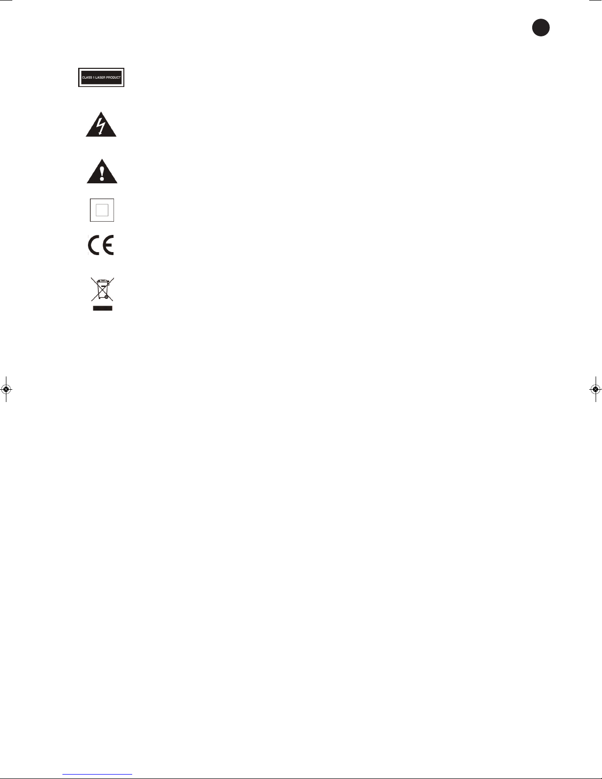
The symbol formed by the expression “Class 1 laser product” written in a rectangle
indicates that visible or invisible laser radiation could be produced. Avoid direct expose to
the laser.
The symbol formed by a ray of lightening inside a triangle shows that the machine has
connection terminals or a circuit with areas with a current which could cause an electric
s
hock, even in normal working conditions.
The symbol formed by an exclamation mark in a triangle shows that the instruction manual
must be referred to for information on how the machine works and its use.
The symbol formed by one square inside another square shows that the machine has
double electrical insulation.
The European Community symbol shows that the machine complies with the current
European Union legislation, as well as its transposition to local legislation.
The symbol of a rubbish bin crossed out and over a horizontal line shows that when the
product is disposed of it must be done properly, placing it in a special selective electronic
and electrical equipment container or through a dealer when purchasing a similar product,
at no additional cost. It also shows that the machine was put on the market after 13th
August 2005 (European Community Directive 2002/96/CE of Electrical and Electronic
recycling, and its Spanish equivalent R.D.208/2005).
In accordance with what is set out in the aforementioned decree, FONESTAR is registered
in the RAEE (Registro de Aparatos Eléctricos y Electrónicos) in a special section REI
(Registro de establecimientos Industriales), with the entry number 001851.
*It is possible that some of these symbols do not appear on the machine.
EXEMPTION OF LIABILITY
The characteristics of the equipment and the content of the manual can change without forewarning.
FONESTAR, S.A. does not assume responsibilities regarding the inappropriate use of the equipment or the
information supplied in this instruction manual, and specifically disclaims any implied liability for marketability
or fitness for any other use.
All rights reserved by FONESTAR, S.A.
EN
Page 4
DESCRIPTION
T
he model MX-4000 is a professional mixer/preamplifier with 5 input channels to 4 output zones with
independent volume control. It is suitable for P.A. and sound system installations with different speaker zones
which need independent volume control.
It counts on 4 balanced mic. Inputs or selectable lines, 1 auxiliary line input and 1 tel. paging telephone
switchboard input assignable to each output channel. It has phantom power supply incorporated and priority
d
epending on the signal level in input 1 and tel. paging in inputs 1, 2 and 3 depending on contact closure.
There are LED indicators available to see the output level of each channel.
CONTROLS AND FUNCTIONS
FRONT PANEL
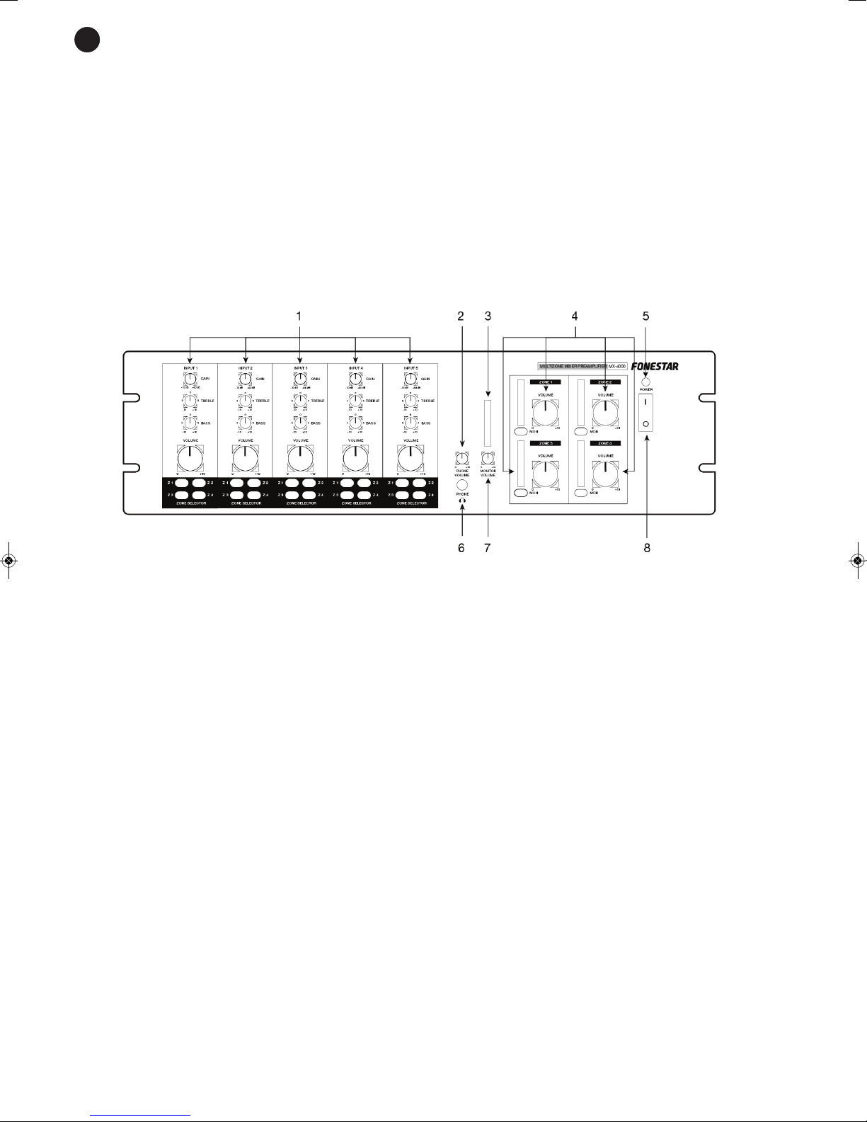
1.- CH1 to CH5 (GAIN, TREBLE, BASS, VOL, ZONE SELECTOR): input zone controls with the following
functions:
GAIN: to adjust the input gain, it lets you control the signal level in a way so as not to produce distortion.
TREBLE, BASS: bass and treble tone control.
VOL: to adjust the output level of the input that is sent to the allocation matrix.
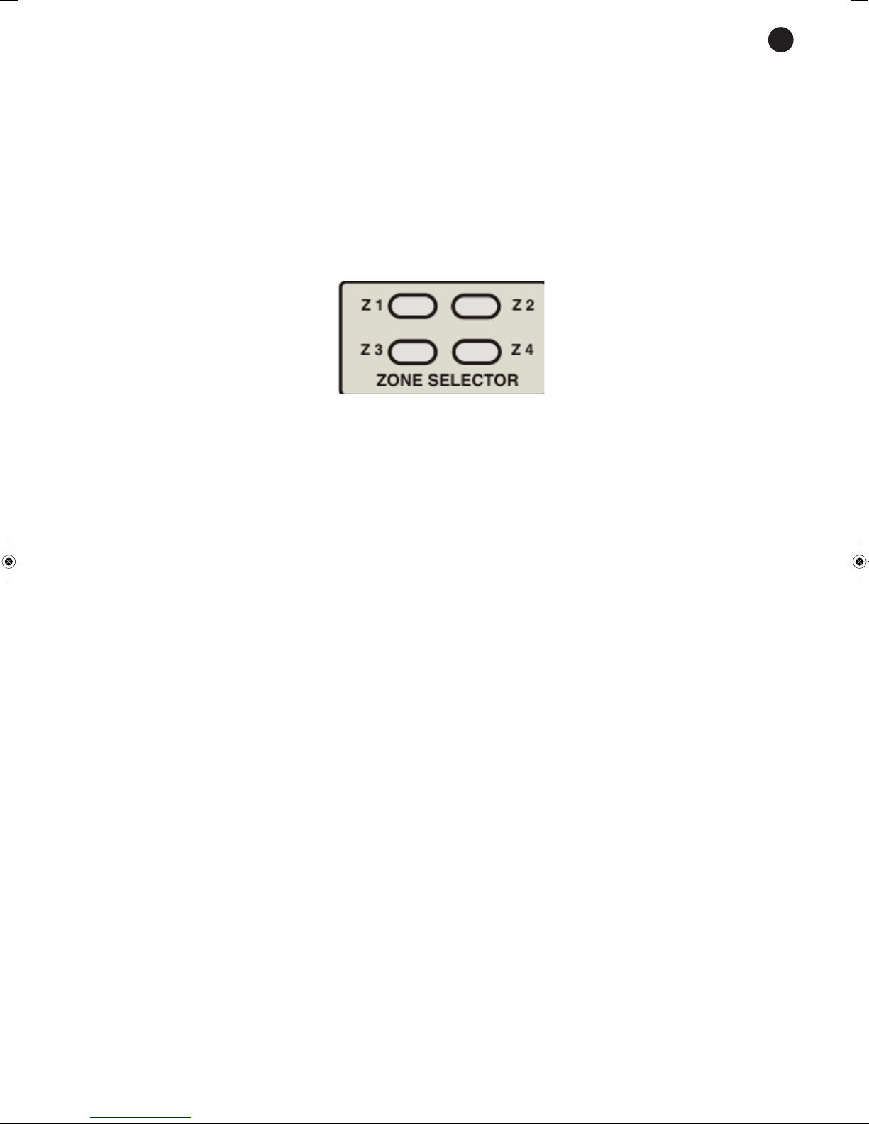
ZONE SELECTOR, Z1 to Z4: these controls let you assign the input signal to one or various output
zones. To assign an input channel to one or various output zones, press the output zone (Z1 to Z4)
buttons in the corresponding input channel, through which you wish it to be listened to.
2. - PHONE VOLUME: headphone output volume control.
3. - LED MONITOR output signal level indicator.
4. - ZONE 1 to ZONE 4: output zone controls, zone 1 to 4 with the following functions:
LED output signal level indicator.
MON: by pressing this button you can monitor the channel signal through the MONITOR output.
VOLUME: zone output level adjustment.
5. - LED Power indicator.
6. - PHONE: headphone output to monitor the output channels assigned to MONITOR.
7. - MONITOR VOLUME: MONITOR output level adjustment.
8. - On/off switch.
- 4-
E
S
EN
Page 5
BACK PANEL
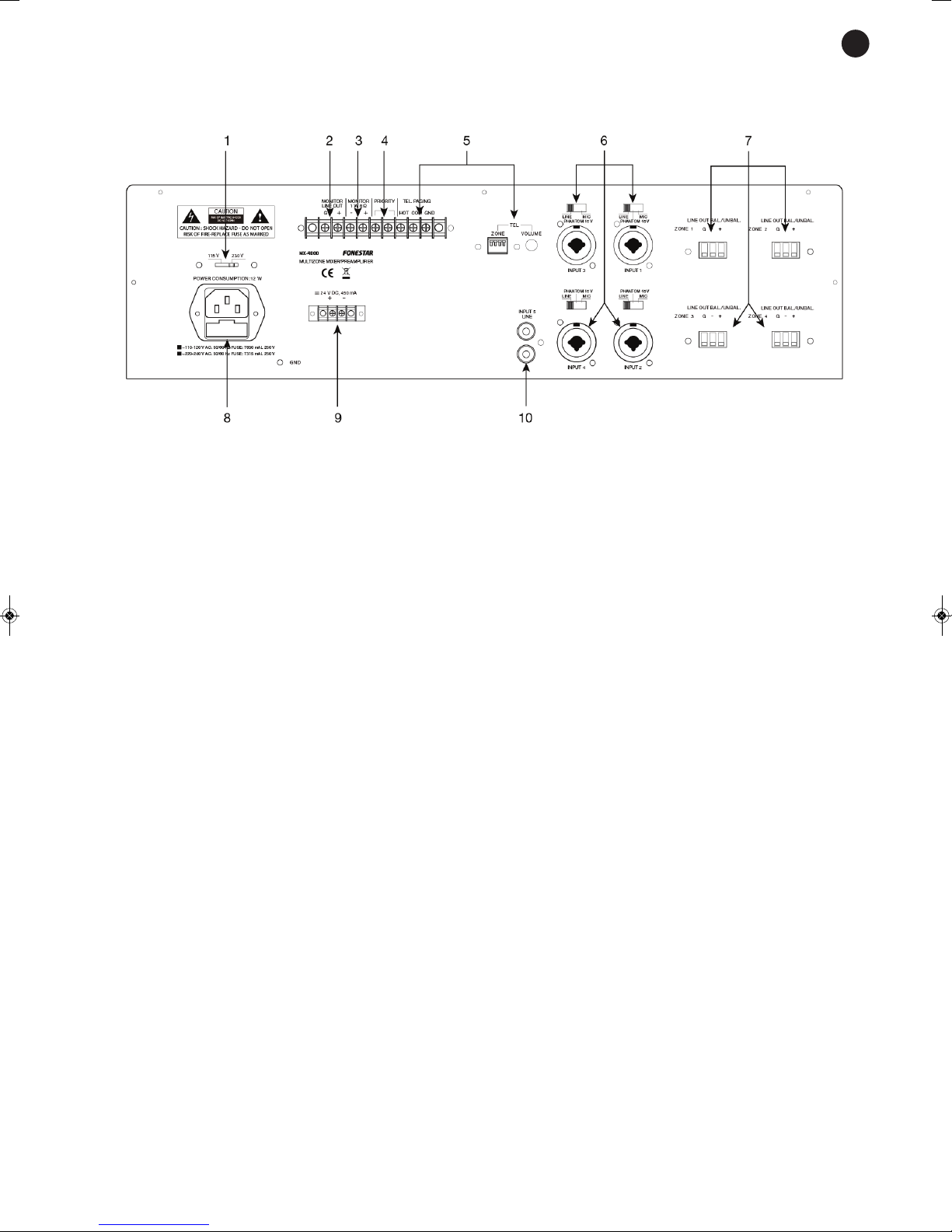
1. - 115-230 V: power supply voltage selector.
2. - MONITOR (LINE OUT): line level output to monitor the output.
3. - MONITOR (1 W, 8 Ω): output for the connection of an 8 Ω low impedance speaker to monitor the output.
4. - PRIORITY: priority in the input channels CH1, CH2 and CH3. By closing these contacts the priority is
activated in the input channels CH1, CH2 and CH3. In this way the rest of the input channels (CH4 and
CH5) are weakened.
5. - TEL. PAGING, ZONE and VOLUME: telephone switchboard signal input with volume control and
priority depending on signal level with 4 switches to choose the zones to assign them to.
6. - Microphone inputs/CH1 line: these inputs use a combo connector (XLR and 6.3 mm stereo jack).
Balanced and unbalanced microphone signals and microphones that require phantom power supply, as
well as balanced or unbalanced line signals can be connected. Using the switch the input is adjusted
depending on the characteristics of the connected signal. These switches have 3 positions:
LINE: in this position, line level audio sources such as a preamplified table microphone can be
connected to inputs CH1 to CH4.
MIC: in this position, balanced or unbalanced, dynamic or electret condenser battery powered
microphones that do not need phantom power supply can be connected to input CH1 to CH4.
PHANTOM: in this position, electret condenser microphones that need phantom power supply (48 V
between pins 2 and 3 of the XLR connector) can be connected to inputs CH1 to CH4. Use this switch
with the volume control at its minimum to avoid damage.
7. - Zone, line out Bal./Unbal: line output for each zone (ZONE 1 to ZONE 4). Balanced line output
Euroblock terminal to connect the zone output signal to an amplifier.
8.- AC power supply socket.
9.- 24 V DC: connection terminals for DC current.
10. -CH5 LINE: auxiliary line input for CD, tape, Tuner, etc. connection, 2 x RCA connectors.
CAUTION: when you connect or disconnect an unbalanced microphone, the switch needs to be in the MIC
position. If the switch is in the PHANTOM position it could cause damage in the microphones. When you use
microphones that do not need phantom power supply, make sure that the switch is in the MIC position, as
the voltage in pins 2 and 3 of the XLR connector can damage the microphones. If in doubt consult your
distributor or the FONESTAR technical service.
- 5-
EN
Page 6
- 6-
CONNECTION
Make the connections with the amplifier and all the system components switched off and disconnected
from the power supply.
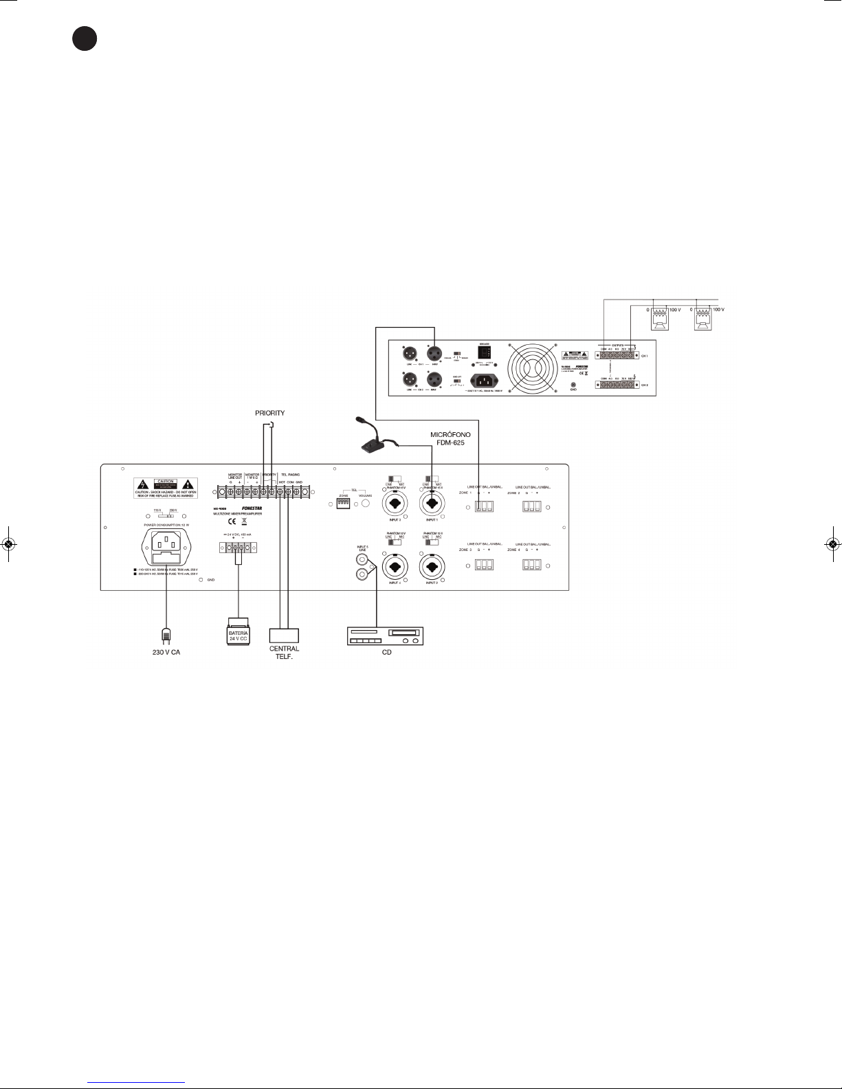
Firstly, connect the audio sources to the inputs. For example, connect a dynamic microphone to the CH1
input and select the MIC position on the input sensitivity selector. If you use a pre-amplified table
microphone, select the LINE position.
Depending on the speaker zones that you are going to use, connect each Zone output terminal, line out
Bal. /Unbal. to the line 1 input amplifier. Then connect the speakers to the amplifiers correctly.
Once the connections have been made according to your needs, connect the system to the mains and
switch it on. After use, do not forget to switch it off and disconnect the system from the mains.
ES
EN
Page 7
INSTRUCTIONS FOR USE
ON AND OFF
Before switching the system on, check that the output volume controls are at their minimum. Switch on the
rest of the audio system, lastly the mixer/preamplifier and adjust the output volume. To switch the system
off, adjust the output volume and switch the mixer/amplifier off, leaving the rest of the system until last.
INPUT CHANNEL ALLOCATION TO OUTPUT ZONES
Each input channel CH1 to CH5 can be allocated independently to one or various output zones ZONE 1 to
ZONE 4.
Using the zone selector buttons Z1, Z2, Z3, Z4 for each channel, found on the front panel, you can choose
the zone where you want the input channel signal to be sent.
For example, if we intend CH1 to be heard in zones 1 and 2 and CH2 in zones 1 and 3, we must select Z1
and Z2 on the CH1 zone selector and Z1 and Z3 on the CH2 zone selector.
PRIORITY IN THE INPUTS
The priority function automatically weakens the level of the inputs with less priority so that the message sent
out by those with more priority can be heard clearly.
The inputs with the maximum priority are tel. paging and CH1 and they are activated by signal level. At the
same time CH1 has priority through contact closure.
To enable the priority function depending on the signal level and on contact closure, you have to change the
jumper. This is found on the inside of the device in the ON position. The jumper is on the printed circuit plate
which is near the connector with the MONITOR outputs, the PRIORITY contacts and the tel. paging input.
We can see where it is found in the following photo:
- 7-
EN
Page 8
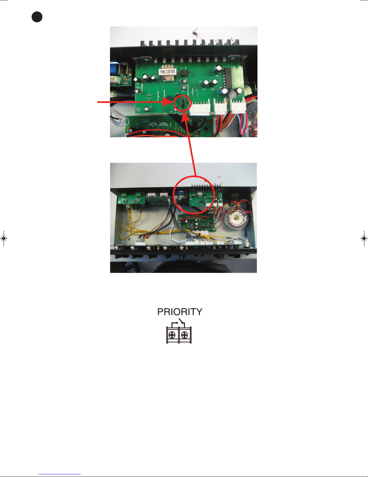
In this way, with the jumper in the ON position, when a signal is detected in the tel. paging input or CH 1
the rest of the inputs (CH2 to CH5) will weaken. Besides, closing the PRIORITY contact on the back panel
with the push button or the switch, the CH2 to CH5 inputs will be weakened automatically.
NOTE: By default, the amplifier is delivered with the jumper in the OFF position. In other words, with priority
deactivated.
- 8-
Jumper to choose priority, depending on signal
level and on contact
closure
E
S
EN
Page 9
TECHNICAL SPECIFICATIONS
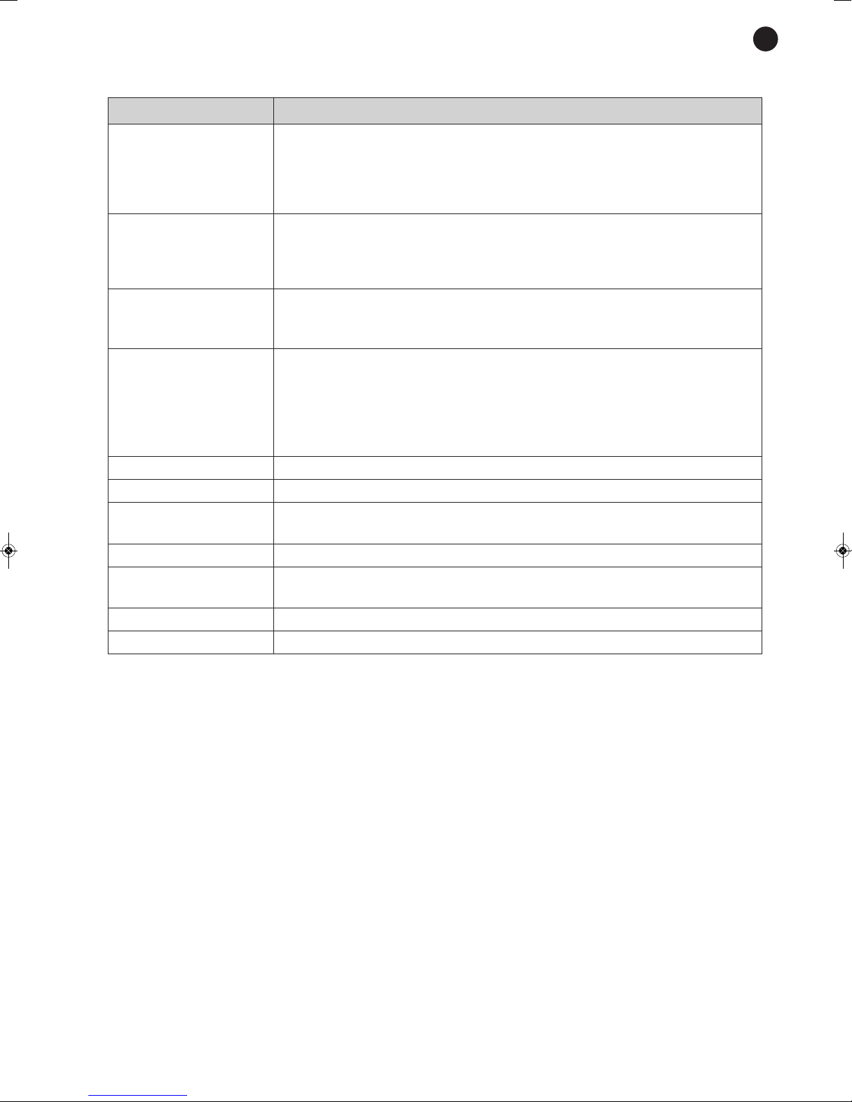
M
X-4000
CHARACTERISTICS Multizone mixer/preamplifier.
Matrix audio system with 5 input channels to 4 output zones.
4 output zones with independent volume control.
P
hantom power supply.
Priority paging.
INPUTS 4 mics./balanced lines, combo (XLR and 6.3 mm jack) 600 Ω 2 mV and
47,000 Ω 150 mV, switchable
1 aux, 2 x RCA 50,000 Ω 300 mV
1 tel. paging, screw terminals 600 Ω 100-300 mV
OUTPUTS 4 balanced or unbalanced zones, euroblock 1 V
1 monitor, screw terminals 600 Ω 775 mV and 1 W 8 Ω
1 stereo headphones, 3.5 mm jack 47 Ω 0.5 W
CONTROLS 4 buttons for zones 1 to 4 for each input channel 1 to 5 and tel. paging
selector to individually assign them to zones 1 to 4
Channels 1 to 5: gain, bass, trebles and volume control
Zones 1 to 4: volume control, monitor selector
Headphone volume
Monitor volume
RESPONSE 20-20,000 Hz ±3 dB
DISTORTION Harmonic: < 0.1 % at 1 kHz
S/N RATIO Microphones > 75 dB
Lines > 90 dB
PHANTOM 15 V in mics 1 to 4, selectable
PRIORITY Tel. paging and input 1 input level priority, selectable
Input 1 through contact closure, selectable
POWER SUPPLY 230/115 V AC, 12 W and 24 V DC, 0.45 A
DIMENSIONS 483 x133 x 222 mm depth. 3 U 19” rack
- 9-
EN
Page 10
WARRANTY
This product has been tested and has passed the corresponding quality control prior to being put on the market.
FONESTAR guarantees the suitability of the product for its specified use during a period of 2 years from the
delivery date and commits itself to repair or substitute the goods as expressed in the Spanish law ‘La Ley General
para la Defensa de los Consumidores y Usuarios, Real Decreto Legislativo 1/2007 16 Noviembre.
The lack of conformity in the first six months after purchase, due to a manufacturing defect, will be rectified with
no more than showing the proof of purchase. After six months FONESTAR reserves the right to demand proof of
the product being sold with that problem.
This warranty does not include damage produced by: inappropriate use or negligence, accidents, worn out parts
due to use, breakages, burns, spilt liquids or other substances, excessive humidity, battery deterioration and
internal manipulation of the device, the software or its components by unauthorized persons, and in general any
use that is unrelated to the nature and purpose of the product.
If any service is needed during the warranty period because of lack of conformity, please contact the business or
distributor where the product was purchased in no more than 2 months after being conscious of the problem. It
is only necessary to contact FONESTAR if it is impossible or imposes an undue burden for them to solve it.
To benefit from this warranty it is necessary to show the proof of purchase with the date clearly visible, with no
corrections or crossing out.
This document adds information, and never decreases the consumers’ rights, which in all cases are protected by
the Spanish law ‘La Ley General para la Defensa de los Consumidores y Usuarios, Real Decreto Legislativo 1/2007
16 Noviembre.
ES
EN
- 10 -
FONESTAR is a member of ECOEMBALAJES ESPAÑA, S.A. “ECOEMBES”, with number 03497 and all our products carry the symbol,
backed by our membership and subscription to the above mentioned organization with the recycling and subsequent management of
our packaging.
FONESTAR S.A. - NIF A28780443 - Polígono Trascueto - 39600 Revilla de Camargo, Cantabria, (España)
www.fonestar.com
Page 11

- 11 -
EN
Page 12

www.fonestar.com
 Loading...