

FONESTAR MPZ-461 Instruction Manual

MPZ-461
MULTIZONE AMPLIFIER WITH USB/SD/MP3
AND FM PLAYER
INSTRUCTION MANUAL

We take this opportunity to thank you for buying this product.
We recommend you read the instruction manual before switching on the machine and follow the instructions
that are given. Keep the manual for future reference.
SECURITY AND THE ENVIRONMENT
ELECTRICAL SECURITY
Check that the current in the mains connection where the machine is to be installed corresponds to the
power supply of the machine.
To avoid damaging the equipment, electrical shocks, fire or physical injury when you connect or disconnect
the equipment from the power supply, pull the plug firmly out of the mains socket holding the plug, never the
cable.
Always do this with dry hands.
Keep the power supply cable far from sources of heat. Do not put heavy objects on top of it or change it.
Clean dust and dirt off the power supply cable regularly.
Do not open the machine; you could get an electric shock.
CAUTION
While installing the machine, make sure it is switched off and unplugged.
Do not open the machine. Touching the internal parts is dangerous and you could receive an electric shock.
The machine must not be splashed or dripped on. Never place recipients with liquid inside on the machine.
Do not place anything inside the machine.
LOCATION
Place the equipment on a horizontal surface with enough space around it to allow ventilation.
Avoid direct sunlight, heat sources and excessive dust.
Do not place the machine near magnetic fields or static electricity.
Do not use surfaces which vibrate or receive impact.
Do not pile machines on top of one another.
VENTILATION
Never block or cover the ventilation slits on the machine.
Do not expose it to direct sunlight or place it near sources of heat.
PERIODS OF INACTIVITY
When the machine is not going to be used for a long period of time, disconnect it from the mains.
If you are using an adapter, take into account that it will continue using electricity even if the machine is
switched off. If it is not going to be used for a long period of time, disconnect it from the mains.
THE ENVIRONMENT
To save energy, switch the machine off when you are not going to use it for a long time. The machine could
contain substances that are harmful to the environment or human health. To minimize the effect of these
substances the machine must be correctly managed and recycled when you decide to dispose of it.
When you dispose of it remember: it cannot be thrown into a conventional rubbish bin.
If it contains or uses batteries, these must be disposed of separately.
The machine (without batteries) must be disposed of correctly. Put it in a container specially intended for the
collection of electronic and electrical appliances, at the dump or hand it over to the dealer when you purchase
similar equipment, so that the dealer can dispose of it correctly (at no added cost).
- 2-
EN
- 3-
SIGNIFICANCE OF THE SYMBOLS ON THE MACHINE*
The symbol formed by the expression “Class 1 laser product” written in a rectangle
indicates that visible or invisible laser radiation could be produced. Avoid direct exposure
to the laser.
The symbol formed by a ray of lightening inside a triangle shows that the machine has
connection terminals or a circuit with areas with a current which could cause an electric
shock, even in normal working conditions.
The symbol formed by an exclamation mark in a triangle shows that the instruction manual
must be referred to for information on how the machine works and its use.
The symbol formed by one square inside another square shows that the machine has
double electrical insulation.
The European Community symbol shows that the machine complies with the current
European Union legislation, as well as its transposition to local legislation.
The symbol of a rubbish bin crossed out and over a horizontal line shows that when the
product is disposed of it must be done properly, placing it in a special selective electronic
and electrical equipment container or through a dealer when purchasing a similar product,
at no additional cost. It also shows that the machine was put on the market after 13th
August 2005 (European Community Directive 2002/96/CE of Electrical and Electronic
recycling, and its Spanish equivalent R.D.208/2005).
In accordance with what is set out in the aforementioned decree, FONESTAR is registered
in the RAEE (Registro de Aparatos Eléctricos y Electrónicos) in a special section REI
(Registro de establecimientos Industriales), with the entry number 001851.
The symbol RoHS (Restriction of Hazardous Substances) shows that the product has been
designed and manufactured restricting the use of certain dangerous material(Directive
2009/95/CE on the restriction of certain dangerous substances in electrical and electronic
appliances, and its transferal to the Spanish regulations, R.D. 208/2005).
*It is possible that some of these symbols do not appear on the machine.
EXEMPTION OF LIABILITY
The characteristics of the equipment and the content of the manual can change without forewarning.
FONESTAR, S.A. does not assume responsibilities regarding the inappropriate use of the equipment or the
information supplied in this instruction manual, and specifically disclaims any implied liability for marketability
or fitness for any other use.
All rights reserved by FONESTAR, S.A
EN

EN
- 4-
DESCRIPTION
Multizone amplifier with 5-input channel matrix and USB/SD/MP3 player with digital FM tuner assignable to
4 output zones with independent volume control. Possibility to page remotely through the paging microphone
mod. M-46.
Suitable for commercial installations with several zones and different music programmes.
CONTROLS AND FUNCTIONS
FRONT PANEL
USB/SD/MP3 - FM MODEL
1.- SD: SD memory card connection slot.
2.- USB/SD/MP3 player with FM tuner information display.
3.- IR: USB/SD/MP3 player remote control infrared signal
receiver.
4.- USB: USB storage device connection port.
5.- MODE: allows selection of the audio source among USB
storage device, SD memory card or the FM radio tuner.
A long press of this button switches the MP3 module on/off.
6.- 12: in USB or SD playback mode, a short press of this button allows playback to be started or paused.
In radio mode, a long press allows the automatic station scan.
7.- REPEAT/RANDOM: in USB or SD playback mode it allows the playback mode to be changed among
the following: 1 (repeat one track), N (normal playback), R (random playback), I (playback of the first 10
seconds of each track), A (repeat all), F (repeat folder).
8.- 7/8: in USB or SD playback mode, a short press of these buttons allows you to go to the previous/next
track. In radio mode, a short press of these buttons allows you to go to the previous/next stored station.
A long press of these buttons allows the volume to be raised or lowered.
9.- LED MUTE indicator which lights up when the MP3 module audio output is deactivated.
10.- MUTE: button which activates/deactivates the MP3 module audio output.
11.- Z1-Z4: allows the USB/SD/MP3 and FM module signal to be assigned to one or several output zones.
When a zone is selected, the corresponding button lights up.
12.- BASS: bass tone control.
13.- TREBLE: treble tone control.
14.- CH LEVEL: knob which regulates the corresponding channel volume.
15.- LED indicator which lights up when the corresponding input channel audio output is deactivated.
16.- MUTE: button which activates/deactivates the corresponding input channel audio output.
17.- MONITOR LEVEL: knob which regulates the monitor output volume.
18.- Z1-Z4: allows the corresponding input signal to be assigned to one or several zones. When a zone is
selected, the corresponding button will light up.
19.- LED signal level indicators of the corresponding output.
20.- MON Z1-Z4: allows the zone in which the MONITOR output will be heard to be selected. When a zone
is selected, the corresponding button will light up.
21.- ZONE 1-4 LEVEL: knob which regulates the output volume in each zone.
22.- POWER/PROT: LED on/off and device protection indicator. If it lights up blue, it indicates that the device
is working correctly. If the amplifier protects itself, the indicator will light up red.
23.- ON/OFF: on/off switch.
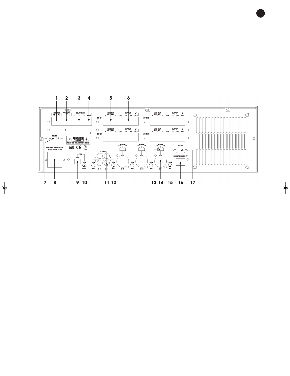
REAR PANEL
1.- MONITOR (1 W, 8 Ω): output for connection of a low impedance loudspeaker 8 Ω to monitor the output.
2.- PRIORITY: when the contact closure of these two terminals is made, change the order of priority of the
inputs.
The order of priority without closing the contacts is as follows:
TEL.PAGING > MIC 1 > Microphone M-46 > MIC 2, MIC 3, LINE 4, LINE 5, USB/SD/MP3 and FM
module.
The order of priority with these contacts closed is the following:
MIC 1 > TEL.PAGING > Microphone M-46 > MIC 2, MIC 3, LINE 4, LINE 5, USB/SD/MP3 and FM
module.
3.- TEL. PAGING: telephone input connection terminals. Allows connection to a telephone switchboard to
page from the switchboard with priority over the rest of the inputs. Make the connection between the
terminals T and G. Consult the characteristics of the switchboard in order to adjust the input level of the
amplifier.
4.- FM ANT: FM aerial input.
5.- LINE OUT: balanced or unbalanced line output. Output signal for recording, mixer, power amplifier,
etc., screw terminal connections.
6.- OUTPUT: loudspeaker general output. For the connection of low impedance loudspeakers 4 Ω and in
high impedance lines of 100 or 70 V, connect the loudspeaker line between the COM terminal and the
impedance or line in V required.
7.- GND LIFT: this selector is normally situated in the GND position. If the installation has ground noises,
place the selector in the LIFT position in order to disconnect the ground and the device’s earth.
8.- AC power supply socket.
9.- ZONE: microswitches to select the zone or zones in which the TEL PAGING input will be heard.
10.- VOLUME: knob which regulates the volume of the TEL PAGING input.
11.- CH 4, CH 5: line level inputs. Allows the connection of audio sources, 2 x RCA connectors.
EN
- 5-
 Loading...