

Page 1
MAZ-6600RU
MULTIZONE AMPLIFIER
INSTRUCTION MANUAL
Page 2

EN
e take this opportunity to thank you for buying this product.
W
We recommend you read the instruction manual before switching on the machine and follow the instructions
that are given. Keep the manual for future reference.
SECURITY AND THE ENVIRONMENT
ELECTRICAL SECURITY
Check that the current in the mains connection where the machine is to be installed corresponds to the
power supply of the machine.
To avoid damaging the equipment, electrical shocks, fire or physical injury when you connect or disconnect
the equipment from the power supply, pull the plug firmly out of the mains socket holding the plug, never the
cable.
Always do this with dry hands.
Keep the power supply cable far from sources of heat. Do not put heavy objects on top of it or change it.
Clean dust and dirt off the power supply cable regularly.
Do not open the machine; you could get an electric shock.
CAUTION
While installing the machine, make sure it is switched off and unplugged.
Do not open the machine. Touching the internal parts is dangerous and you could receive an electric shock.
The machine must not be splashed or dripped on. Never place recipients with liquid inside on the machine.
Do not place anything inside the machine.
LOCATION
Place the equipment on a horizontal surface with enough space around it to allow ventilation.
Avoid direct sunlight, heat sources and excessive dust.
Do not place the machine near magnetic fields or static electricity.
Do not use surfaces which vibrate or receive impact.
Do not pile machines on top of one another.
VENTILATION
Never block or cover the ventilation slits on the machine.
Do not expose it to direct sunlight or place it near sources of heat.
PERIODS OF INACTIVITY
When the machine is not going to be used for a long period of time, disconnect it from the mains.
If you are using an adapter, take into account that it will continue using electricity even if the machine is
switched off. If it is not going to be used for a long period of time, disconnect it from the mains.
THE ENVIRONMENT
To save energy, switch the machine off when you are not going to use it for a long time. The machine could
contain substances that are harmful to the environment or human health. To minimize the effect of these
substances the machine must be correctly managed and recycled when you decide to dispose of it.
When you dispose of it remember: it cannot be thrown into a conventional rubbish bin.
If it contains or uses batteries, these must be disposed of separately.
The machine (without batteries) must be disposed of correctly. Put it in a container specially intended for the
collection of electronic and electrical appliances, at the dump or hand it over to the dealer when you purchase
similar equipment, so that the dealer can dispose of it correctly (at no added cost).
- 2-
Page 3
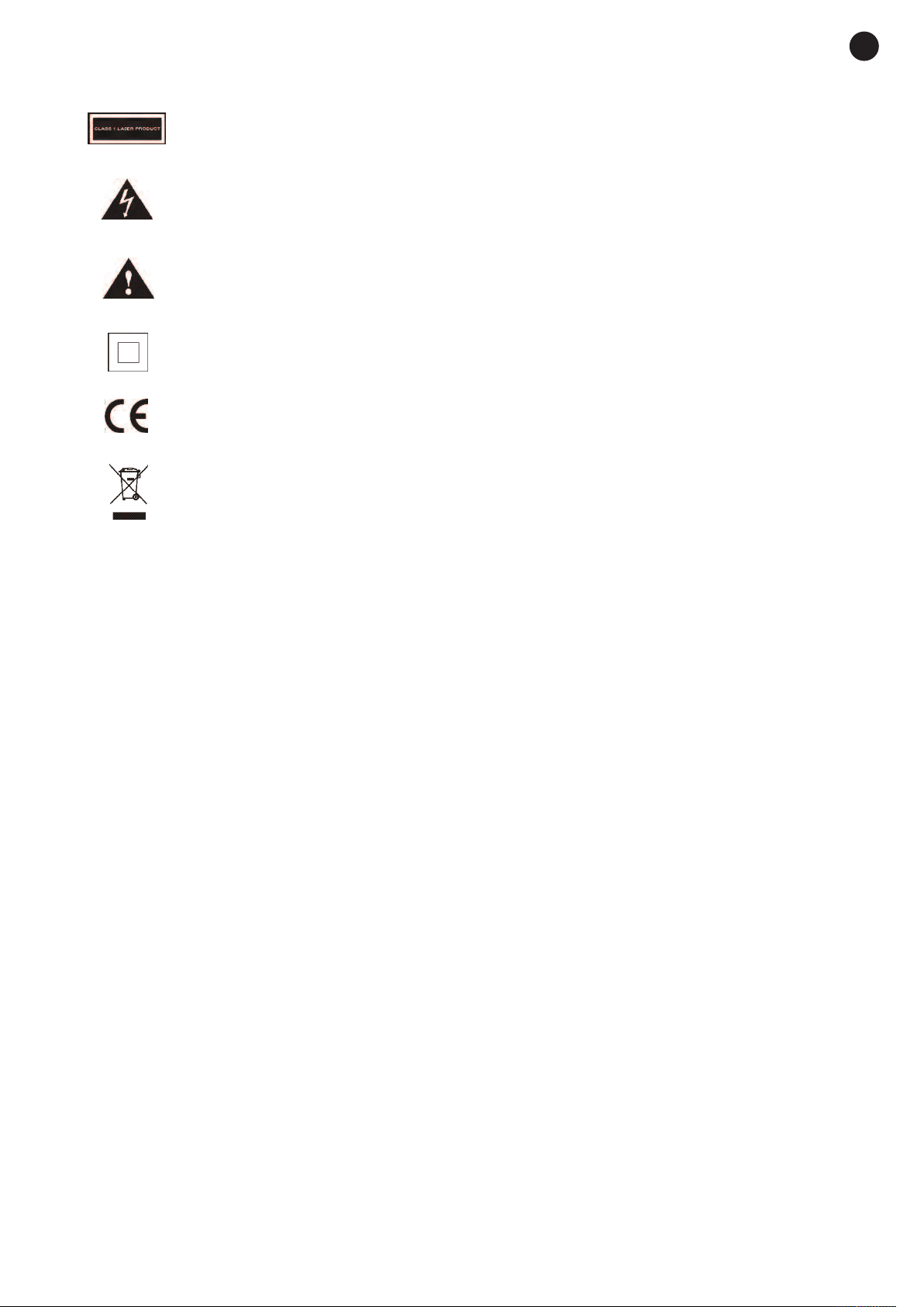
SIGNIFICANCE OF THE SYMBOLS ON THE MACHINE*
The symbol formed by the expression “Class 1 laser product” written in a rectangle
indicates that visible or invisible laser radiation could be produced. Avoid direct exposure
to the laser.
The symbol formed by a ray of lightening inside a triangle shows that the machine has
connection terminals or a circuit with areas with a current which could cause an electric
shock, even in normal working conditions.
The symbol formed by an exclamation mark in a triangle shows that the instruction manual
must be referred to for information on how the machine works and its use.
The symbol formed by one square inside another square shows that the machine has
double electrical insulation.
The European Community symbol shows that the machine complies with the current
European Union legislation, as well as its transposition to local legislation.
The symbol of a rubbish bin crossed out and over a horizontal line shows that when the
product is disposed of it must be done properly, placing it in a special selective electronic
and electrical equipment container or through a dealer when purchasing a similar product,
at no additional cost. It also shows that the machine was put on the market after 13th
August 2005 (European Community Directive 2012/19/EU of Electrical and Electronic
recycling, and its Spanish equivalent R.D.219/2013).
EN
In accordance with what is set out in the aforementioned decree, FONESTAR is registered
in the RAEE (Registro de Aparatos Eléctricos y Electrónicos) in a special section REI
(Registro de establecimientos Industriales), with the entry number 001851.
*It is possible that some of these symbols do not appear on the machine.
EXEMPTION OF LIABILITY
The characteristics of the equipment and the content of the manual can change without forewarning.
FONESTAR, S.A. does not assume responsibilities regarding the inappropriate use of the equipment or the
information supplied in this instruction manual, and specifically disclaims any implied liability for marketability
or fitness for any other use.
All rights reserved by FONESTAR, S.A.
- 3-
Page 4

EN
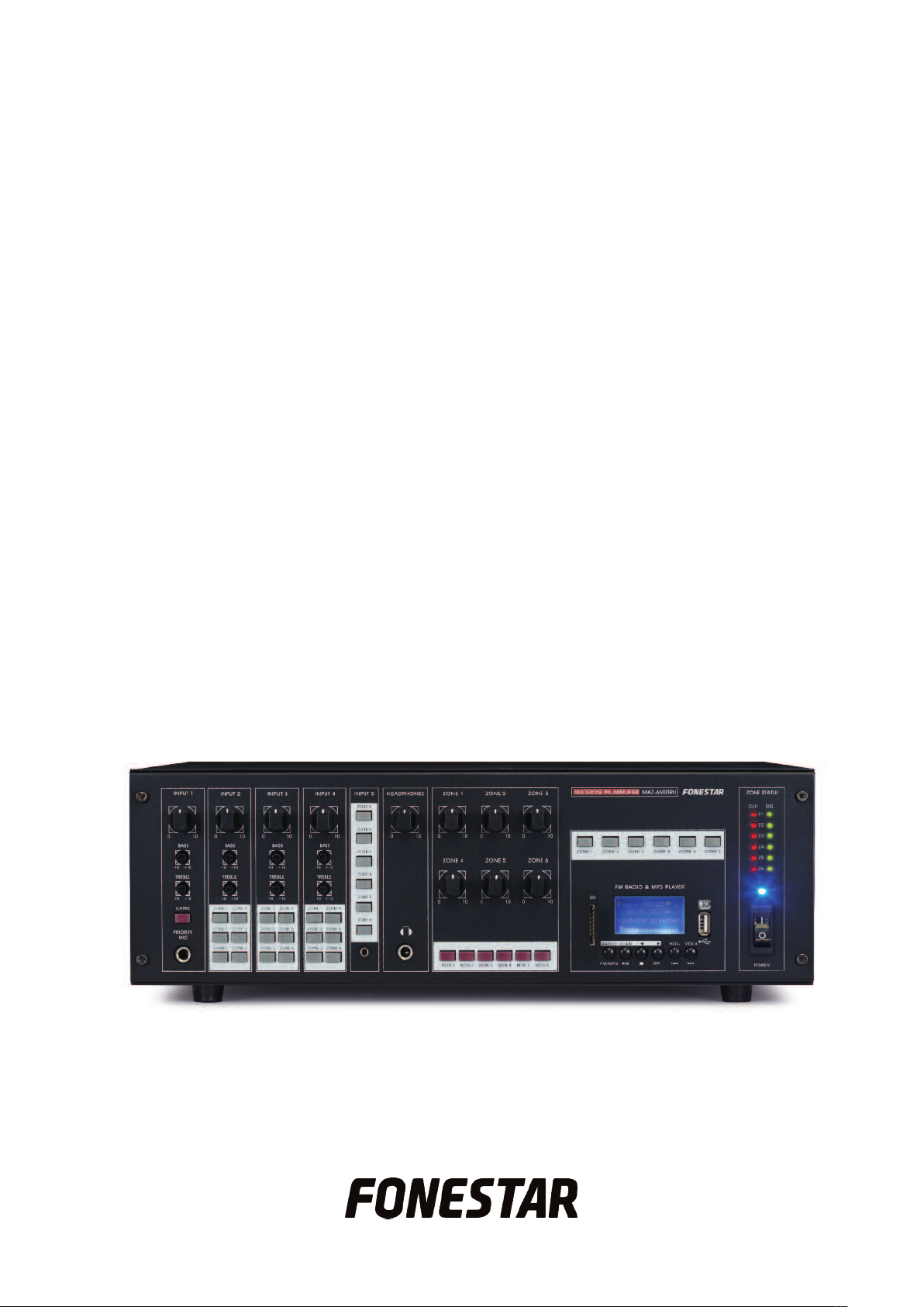
DESCRIPTION
- Multizone amplifier with matrix with 5 input channels to 6 output zones with independent volume control.
- USB/SD/MP3 player with digital FM radio tuner.
- Suitable for commercial installations with several zones and different musical programs.
CONTROLS AND FUNCTIONS
FRONT PANEL
1.- INPUT 1: input 1 volume control.
2.- BASS/TREBLE (INPUT 1): strengthens or weakens the bass and treble frequencies from channel 1, ±10
dB.
3.- CHIME: button that activates the musical chimes. The audio in the rest of the inputs is automatically
cut off and only the mic input INPUT 1 can be heard.
4.- PRIORITY MIC: priority mic. level input, 6.3 mm jack connector.
5.- INPUT 2-4: volume controls for inputs 2-4.
6.- BASS/TREBLE (INPUT 2-4): strengthens or weakens the bass/treble frequencies in channels 2-4, ±10 dB.
7.- ZONE 1-6 (INPUT 2-4): controls for allocating the corresponding input signal to one or several output
zones. To allocate one input channel to one or several output zones, press the output zone buttons
(ZONE 1 to 6) in the corresponding input channel, depending on the which one you want the selected
input channel to be heard through.
8.- ZONE 1-6 (INPUT 5): controls for allocating the input 5 signal to one or several output zones. To allocate
input channel 5 to one or several output zones, press the output zone buttons (ZONE 1 to 6), depending
on which one you want it to be heard through.
9.- INPUT 5: line level auxiliary input, 3.5 mm jack connector.
10.- HEADPHONES: headphone output volume control.
11.- Headphone output, 6.3 mm jack connector.
12.- ZONE 1-6: output zone volume controls.
13.- MON 1-6: controls for allocating the desired output zone signal to the monitor output (headphones). To
allocate the desired output zone to the headphone output, press the corresponding MON 1-6 button.
14.- ZONE 1-6 (FM RADIO & MP3 PLAYER): controls for allocating the USB/SD/MP3 player module and
radio tuner signal to one or several output zones. To allocate this channel, press the output zone buttons
(ZONE 1 to 6) you want to hear it through.
15.- USB/SD/MP3 player module with digital FM tuner.
16.- CLIP Z1-Z6: LED clip indicators for output zones 1 to 6. They light up red when the level in the
corresponding output zone is very high. Lower the volume using the corresponding controls until the
LED indicator does not light up or it does so occasionally.
- 4-
Page 5

7.- SIGNAL Z1-Z6: LED indicators for output zone 1 to 6 signals. They light up green when a signal is
1
detected in the corresponding output zones.
18.- LED power indictor for the equipment (blue).
19.- POWER: amplifier on/off switch.
USB/SD/MP3 PLAYER WITH REMOTE CONTROL
EN
1.- Information display for the USB/SD/MP3 player module.
2.- SD: SD card connection port.
3.- Remote control infrared receiver.
4.- Connection port for USB storage devices.
5.- FM/MP3: one short press of this button lets you change from FM radio tuner to USB storage device or
SD memory card.
One long press in this mode lets you access the MP3 menu, where you can choose from the following
options:
- Equalization (EQ)
- Playback mode (PLAY MODE)
- CHANGE DEVICE
Access each submenu using button 12, browse through the options using buttons 7/8 and select the
desired option using button 12.
6.- 12: for starting or pausing playback.
It also lets you access the submenus in the MP3 menu and confirm the selected option.
7.- 3: stops playback.
8.- RPT: for selecting playback mode.
9.- 7/8: a short press of these buttons lets you move to the previous/following song.
One long press of these buttons lets you turn the player volume up/down.
It also lets you browse through the menu and MP3 submenu options.
10.- PLAY PAUSE (12): for starting or pausing playback.
It also lets you access the submenus in the MP3 menu and confirm the selected option.
11.- EQ: for changing between the different existing equalizations.
12.- VOL-/VOL+: for turning the player volume up/down.
13.- 7/8: one short press lets you pass to the previous/following song.
- 5-
Page 6

EN
ne long press fast forwards/rewinds playback.
O
It also lets you browse through the menu and MP3 submenu options.
14.- 0-9: direct selection number buttons for playing a certain audio track.
15.- ENTER: for accessing the MP3 menu, where the following options can be chosen:
- Equalization (EQ)
- Playback mode (PLAY MODE)
- CHANGE DEVICE
Access each submenu using the 12 button, browse through the options using the 7/8 button and
select the desired option with the 12 button.
16.- MODE: pressing this button consecutively lets you change from the FM radio tuner to the USB storage
device or the SD memory card.
One long press on this button switches the player module off.
DIGITAL FM RADIO TUNER WITH REMOTE CONTROL
1.- USB/SD/MP3 player module information display.
2.- SD: connection port for SD cards.
3.- Infrared receiver for the remote control.
4.- Connection port for USB storage devices.
5.- RADIO: one short press on this button lets you change from the FM radio tuner to the USB storage
device or the SD memory card.
One long press in this mode lets you access the radio menu, where you can choose from the following
options:
- AUTO SEARCH
- DELETE STATION
- DELETE ALL STATIONS
Access each submenu using the 12 button, browse through the options using the 7/8 buttons and
select the desired option using the 12 button.
6.- SCAN: tunes the FM radio stations automatically. Tuning starts from the lowest frequency and the
stations will be saved automatically in consecutive memory positions.
7.- Button for moving to the previous frequency point in 0.1 MHz steps.
8.- Button for moving to the next frequency point in 0.1 MHz steps.
9.- 7/8: one short press of these buttons lets you pass to the previous/following tuned station.
One long press of these buttons lets you turn the radio tuner volume up/down.
- 6-
Page 7

EN
t also lets you browse through the radio menu and MP3 submenus.
I
10.- PLAY PAUSE (12): for tuning the FM radio stations automatically. Tuning starts from the lowest
frequency Tuning starts from the lowest frequency and the stations will be saved automatically in
consecutive memory positions.
11.- CH-/CH+: Buttons for moving to the previous/following frequency point in 0.1 MHz steps.
12.- VOL-/VOL+: for turning the player volume up/down.
13.- 7/8: passes to the next/following tuned station.
14.- ENTER: for accessing the radio menu, where you can choose from the following options:
- AUTO SEARCH
- DELETE STATION
- DELETE ALL STATIONS
Access each submenu using the 12 button, browse through the options using the 7/8 buttons and
select the desired option using the 12 button.
15.- MODE: short consecutive presses on this button will let you change from the FM radio tuner to the
USB storage device or SD memory card.
One long press on this button lets you switch the player module off.
- 7-
Page 8

EN
BACK PANEL
1.- FM ANTENNA: aerial input for the digital FM tuner.
2.- Power supply voltage selector.
3.- Input for AC mains connection.
4.- Earth screw, to be used if it is not already incorporated in the mains.
5.- ZONE 1-6: output for the speakers in each zone. For low impedance 8 Ω speaker connection and high
impedance 100/70 V lines. Connect the speaker line between the COM terminal and the impedance or
line in the desired voltage (V).
6.- PRIORITY: INPUT 1 priority terminals using contact closure. Shortcircuit these terminals to activate
priority in input 1. The rest of the inputs will be silenced automatically.
7.- Operating mode selector for INPUT 4. Move the switch to the TAPE, CD or AUX position, depending on
the input you are going to use. The inputs have a different sensitivity level.
8.- INPUT 4: auxiliary line inputs, 2 x RCA connectors. Move the switch on the top of the inputs to the
appropriate position depending on the input being used.
9.- LINE/PHANTOM 48 V/MIC: sensitivity switches for inputs 2-3 and 48 V phantom power. These
switches have three positions:
LINE: in this position, line level audio sources, CD players, etc. can be connected to inputs 2-3.
PHANTOM 48 V: in this position, electret condenser microphones that require 48 V phantom power can
be connected to inputs 2-3.
MIC: in this position, 30-600 Ω low impedance dynamic microphones can be connected to inputs 2-3.
10.- INPUT 2-3: microphone/line inputs, combo connectors (XLR and 6.3 mm jack).
11.- PRIORITY: priority switch for INPUT 1. In the OFF position, input 1 has no priority over the other inputs.
Move the switch to the ON position and input 1 will have priority over the rest of the inputs, and these
will weaken depending on the level selected with the MUTE SENS control.
12.- MUTE SENS: control for activating/deactivating priority in INPUT 1. Turn the control wheel clockwise
to its maximum and the rest of the inputs will weaken automatically when a signal is detected in INPUT
1. Turn it anti-clockwise and the priority function will go to its minimum level.
- 8-
Page 9

EN
CONNECTION
- Make the connections with the amplifier and all the components in the installation switched off and
disconnected from the mains.
- Connect a microphone to the PRIORITY MIC (INPUT 1) on the front panel. The attenuation level for this
input can be regulated using the MUTE SENS control on the back panel of the equipment.
- Connect the desired audio equipment or microphones to the corresponding inputs. If a dynamic
microphone is connected to inputs 2 or 3, move the switch to the MIC position. If a condenser microphone
is connected, move the switch to the PHANTOM 48 V position.
If a line level source is connected to input 2 or 3, move the switch to the LINE position.
- If you wish, you can connect a line level source to INPUT 4, which has been prepared for this. Move the
switch that is over the inputs to the corresponding position, depending on the input you used.
- If you wish, connect a line level source to INPUT 5 on the front panel. Assign this input to the desired
output zones using the ZONE 1-6 controls for input 5.
- If you use the 8 Ω low impedance output, you must connect the speakers in a series/parallel circuit so that
the speaker charge impedance is the same as the amplifier output impedance and the power supplied by
the amplifier does not exceed what is withstood by the speakers.
- If you use 100 or 70 V high impedance line output, you must connect all the speakers in parallel and the sum
of the power of all the speakers must not exceed the power supplied by the amplifier.
- Power the MAZ-6600RU amplifier using the AC mains supply.
- Once the connections have been made according to your needs, connect the equipment to the mains and
switch it on. After use do not forget to switch it off and disconnect the equipment from the mains.
- 9-
Page 10

EN
SPECIFICATIONS
MAZ-6600RU
CHARACTERISTICS Multizone amplifier.
Allocation matrix with 5 input channels to 6 output zones.
USB/SD player for MP3 files.
Digital FM radio tuner.
6 zones with independent volume control.
Phantom power supply.
Musical chimes.
Paging priority.
Remote control for USB/SD/MP3/FM player.
POWER 6 x 100 W RMS
RESPONSE 80-18 000 Hz ±3 dB
DISTORTION Harmonic: < 1%
S/N RATIO Microphones: > 65 dB
Auxiliaries: > 75 dB
INPUTS 1 unbalanced mic., 6.3 mm jack, 5 mV
2 balanced mics./lines, combo (XLR and 6.3 mm jack) 5 mV and 175
mV, switchable
1 stereo TAPE/CD/AUX auxiliary, 2 x RCA 220 mV, 150 mV, 110 mV,
selectable
1 stereo auxiliary, 3.5 mm jack. 100 mV
OUTPUTS 1 stereo monitor, 6.3 mm jack
CONTROLS 6 zone buttons (1 to 6) for each input channel (2 to 5) and
USB/SD/MP3/FM player
Channels 1 to 4: volume control, bass and treble
Zones 1 to 6: volume control, monitor selector
Monitor volume
PLAYER USB/SD/MP3 player and digital FM tuner with pretuned channels and
auto scan
PHANTOM 48 V in mics. 2 to 3, selectable
PRIORITY Mic. 1 through signal level or contact closure, selectable
IMPEDANCE 6 zones: 8 Ω and 100 and 70 V lines, screw terminals
POWER SUPPLY 230/115 V AC, 1000 W maximum
DIMENSIONS 481 x 133 x 341 mm depth. 3 U 19" rack
ACCESSORIES FM aerial
Mounts for assembling in 19" rack
- 10 -
Page 11

DECLARATION OF CONFORMITY
FONESTAR SISTEMAS S.A.
Polígono de Trascueto s/n
39600 Revilla de Camargo, Cantabria (Spain)
Declares, under its responsibility, that the following equipment:
Description: Multizone Amplifier
Brand: FONESTAR
Model: MAZ-6600RU
complies with the European Community directives 2004/108/CE on Electromagnetic Compatibility,
2006/95/CE on Low Voltage and 2011/65/UE on the restriction of certain dangerous substances in
electrical and electronic appliances (RoHS).
Santander, 27th February 2015
EN
Juan Vallejo
Technical Engineer, Sales Department
WARRANTY
This product has been tested and has passed the corresponding quality control prior to being put on the market.
FONESTAR guarantees the suitability of the product for its specified use during a period of 2 years from the
delivery date and commits itself to repair or substitute the goods as expressed in the Spanish law ‘La Ley
General para la Defensa de los Consumidores y Usuarios, Real Decreto Legislativo 1/2007 16 Noviembre.
The lack of conformity in the first six months after purchase, due to a manufacturing defect, will be rectified with
no more than showing the proof of purchase. After six months FONESTAR reserves the right to demand proof of
the product being sold with that problem.
This warranty does not include damage produced by: inappropriate use or negligence, accidents, worn out parts
due to use, breakages, burns, spilt liquids or other substances, excessive humidity, battery deterioration and
internal manipulation of the device, the software or its components by unauthorized persons, and in general any
use that is unrelated to the nature and purpose of the product.
If any service is needed during the warranty period because of lack of conformity, please contact the business or
distributor where the product was purchased in no more than 2 months after being conscious of the problem. It is
only necessary to contact FONESTAR if it is impossible or imposes an undue burden for them to solve it.
To benefit from this warranty it is necessary to show the proof of purchase with the date clearly visible, with no
corrections or crossing out.
This document adds information, and never decreases the consumers’ rights, which in all cases are protected by
the Spanish law ‘La Ley General para la Defensa de los Consumidores y Usuarios, Real Decreto Legislativo
1/2007 16 Noviembre.
FONESTAR is a member of ECOEMBALAJES ESPAÑA, S.A. “ECOEMBES”, with number 03497 and all our
products carry the symbol, backed by our membership and subscription to the above mentioned organization
with the recycling and subsequent management of our packaging.
FONESTAR S.A. - NIF A28780443 - Apartado 191 - 39080 - Santander, Cantabria, (Spain)
www.fonestar.com
- 11 -
 Loading...