

Page 1
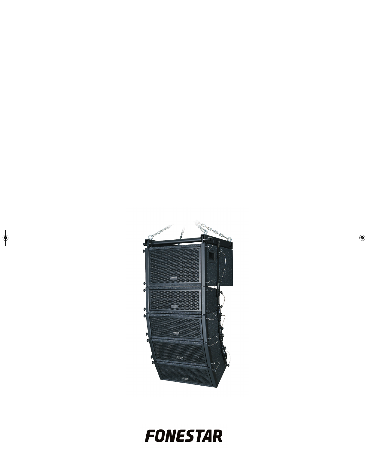
ARRAY-530
COMPACT LINE ARRAY SYSTEM
INSTRUCTION MANUAL
Page 2

We take this opportunity to thank you for buying this product.
W
e recommend you read the instruction manual before switching on the machine and follow the instructions
that are given. Keep the manual for future reference.
SECURITY AND THE ENVIRONMENT
ELECTRICAL SECURITY
C
heck that the current in the mains connection where the machine is to be installed corresponds to the
power supply of the machine.
To avoid damaging the equipment, electrical shocks, fire or physical injury when you connect or disconnect
the equipment from the power supply, pull the plug firmly out of the mains socket holding the plug, never the
cable.
Always do this with dry hands.
Keep the power supply cable far from sources of heat. Do not put heavy objects on top of it or change it.
Clean dust and dirt off the power supply cable regularly.
Do not open the machine; you could get an electric shock.
CAUTION
While installing the machine, make sure it is switched off and unplugged.
Do not open the machine. Touching the internal parts is dangerous and you could receive an electric shock.
The machine must not be splashed or dripped on. Never place recipients with liquid inside on the machine.
Do not place anything inside the machine.
LOCATION
Place the equipment on a horizontal surface with enough space around it to allow ventilation.
Avoid direct sunlight, heat sources and excessive dust.
Do not place the machine near magnetic fields or static electricity.
Do not use surfaces which vibrate or receive impact.
Do not pile machines on top of one another.
VENTILATION
Never block or cover the ventilation slits on the machine.
Do not expose it to direct sunlight or place it near sources of heat.
PERIODS OF INACTIVITY
When the machine is not going to be used for a long period of time, disconnect it from the mains.
If you are using an adapter, take into account that it will continue using electricity even if the machine is
switched off. If it is not going to be used for a long period of time, disconnect it from the mains.
THE ENVIRONMENT
To save energy, switch the machine off when you are not going to use it for a long time. The machine could
contain substances that are harmful to the environment or human health. To minimize the effect of these
substances the machine must be correctly managed and recycled when you decide to dispose of it.
When you dispose of it remember: it cannot be thrown into a conventional rubbish bin.
If it contains or uses batteries, these must be disposed of separately.
The machine (without batteries) must be disposed of correctly. Put it in a container specially intended for the
collection of electronic and electrical appliances, at the dump or hand it over to the dealer when you purchase
similar equipment, so that the dealer can dispose of it correctly (at no added cost)
- 2-
E
N
Page 3
E
N
- 3-
SIGNIFICANCE OF THE SYMBOLS ON THE MACHINE*
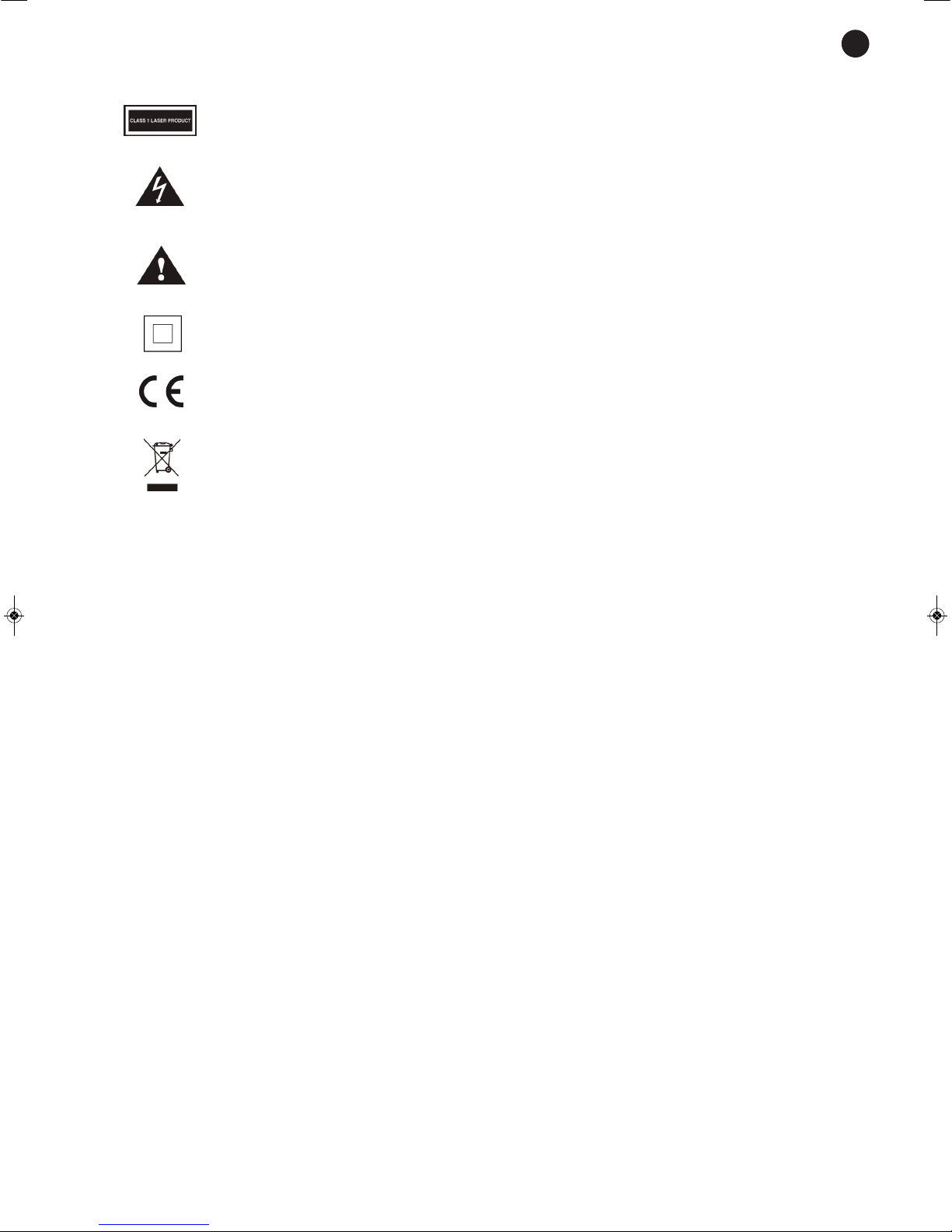
The symbol formed by the expression “Class 1 laser product” written in a rectangle
indicates that visible or invisible laser radiation could be produced. Avoid direct exposure
to the laser.
The symbol formed by a ray of lightening inside a triangle shows that the machine has
c
onnection terminals or a circuit with areas with a current which could cause an electric
shock, even in normal working conditions.
The symbol formed by an exclamation mark in a triangle shows that the instruction manual
must be referred to for information on how the machine works and its use.
The symbol formed by one square inside another square shows that the machine has
double electrical insulation.
The European Community symbol shows that the machine complies with the current
European Union legislation, as well as its transposition to local legislation.
The symbol of a rubbish bin crossed out and over a horizontal line shows that when the
product is disposed of it must be done properly, placing it in a special selective electronic
and electrical equipment container or through a dealer when purchasing a similar product,
at no additional cost. It also shows that the machine was put on the market after 13th
August 2005 (European Community Directive 2002/96/CE of Electrical and Electronic
recycling, and its Spanish equivalent R.D.208/2005).
In accordance with what is set out in the aforementioned decree, FONESTAR is registered
in the RAEE (Registro de Aparatos Eléctricos y Electrónicos) in a special section REI
(Registro de establecimientos Industriales), with the entry number 001851.
The symbol RoHS (Restriction of Hazardous Substances) shows that the product has been
designed and manufactured restricting the use of certain dangerous material(Directive
2002/95/CE on the restriction of certain dangerous substances in electrical and electronic
appliances, and its transferal to the Spanish regulations, R.D. 208/2005).
*It is possible that some of these symbols do not appear on the machine.
EXEMPTION OF LIABILITY
The characteristics of the equipment and the content of the manual can change without forewarning.
FONESTAR, S.A. does not assume responsibilities regarding the inappropriate use of the equipment or the
information supplied in this instruction manual, and specifically disclaims any implied liability for marketability
or fitness for any other use.
All rights reserved by FONESTAR, S.A.
Page 4
INTRODUCTION
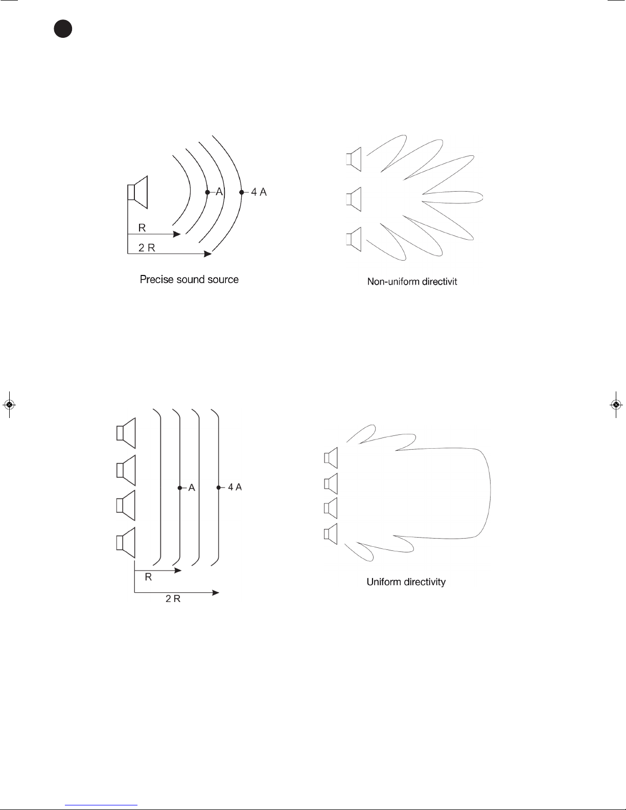
Conventional loudspeaker systems are made up of a powerful loudspeaker or a set of them. A loudspeaker
behaves as a precise sound source with 6 dB attenuation each time the distance from the source is doubled.
Furthermore, a set of loudspeakers positioned vertically are not optimized so that the audio from each loudspeaker adds to the rest, producing a directivity pattern with lobes due to the audio cancellation being produced.
Line array audio systems have been designed to obtain maximum performance and uniform audio in the
audience zone.
The system loudspeakers are positioned in the line array to achieve consistant audio from what is transmitted
by each, one altogether. In this way, the line array loudspeakers all together behave as a lineal audio source.
In this case, each time that the distance is doubled the audio attenuation is 3 dB. It also achieves a narrowing
of the vertical coverage angle, an increase in directivity and therefore, higher and more uniform audio levels
distributed through the audience area.
- 4-
E
N
Page 5
- 5-
E
N
DESCRIPTION
The compact line array system is made up of:
-
Subwoofer.
- 4 mid-treble loudspeakers.
- Rigging system with upper mount, front and back joints, and quick safety pins.
It provides maximum audio quality thanks to its excellent frequency response.
Adjustable tilt in the mid-treble speakers to achieve uniform coverage in the audience zone.
Suitable for all types of conference rooms, theatres, halls, etc.
CONTROLS AND FUNCTIONS
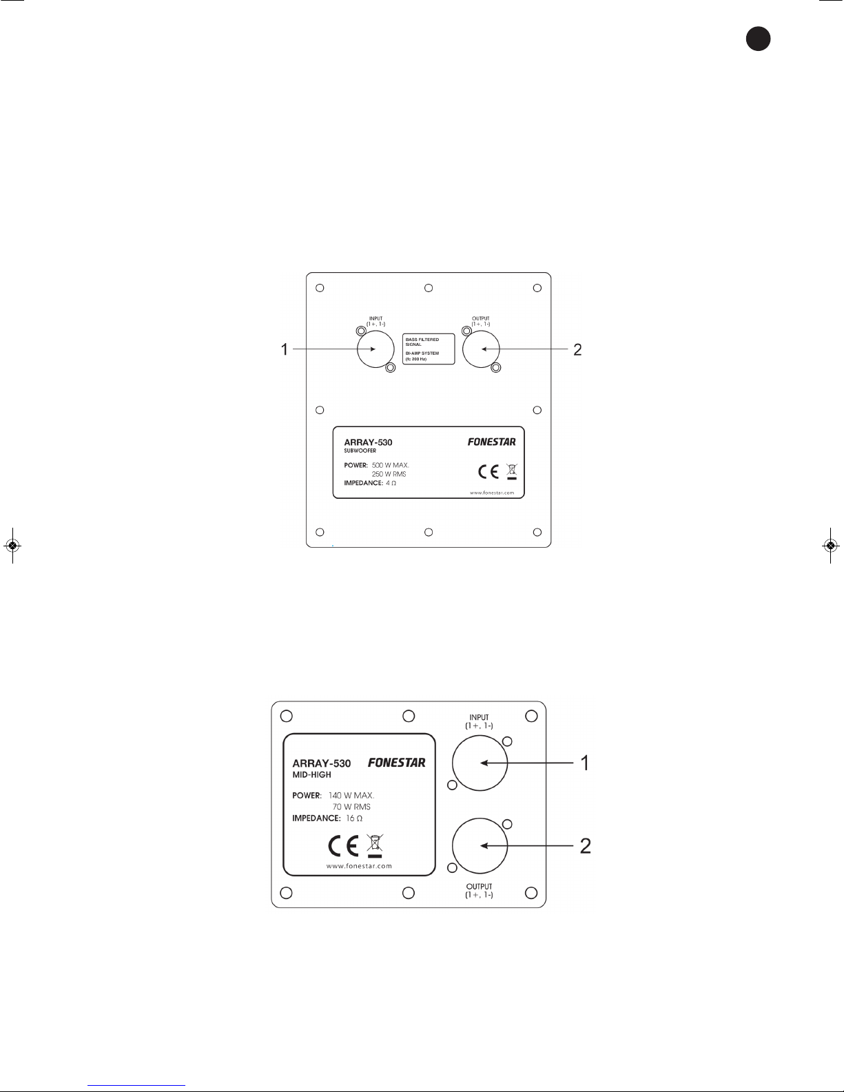
SUBWOOFER BACK PANEL
1.- INPUT: subwoofer input. For connecting the bass amplifier output, speaker connector. The connection
uses the 1+, 1- circuit of the speaker connector. The input signal must be filtered with a low-pass filter
with a frequency of 200 Hz.
2.- OUTPUT: subwoofer output, speaker connector.
LOUDSPEAKER BACK PANEL
1.- INPUT: loudspeaker input. For connecting the mid-treble amplifier output, speaker connector. The
connection uses the 1+, 1- circuit of the speaker connector.
2.- OUTPUT: Loudspeaker output. For connecting to the input on the next loudspeaker, speaker connector.
Page 6
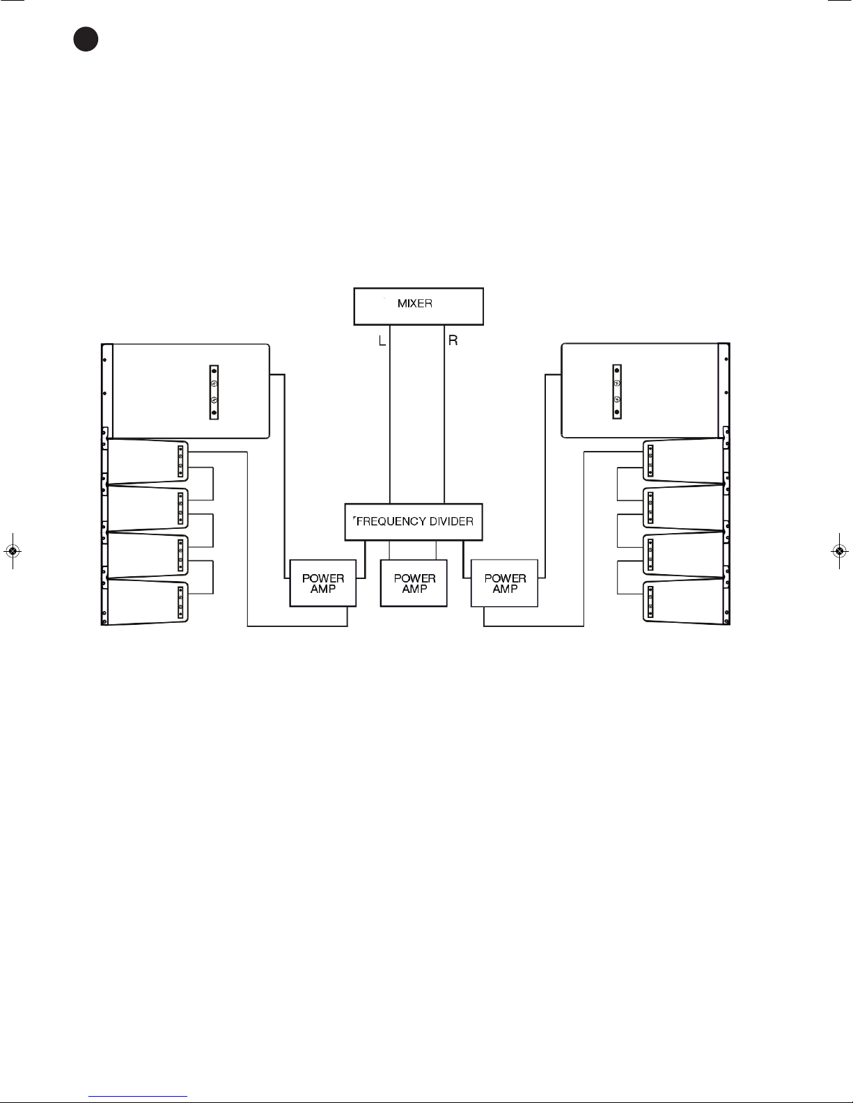
CONNECTION
Make the connections with the equipment switched off and disconnected from the mains.
We recommend filtering the signal before passing it through the subwoofer, using a frequency divider to
achieve a better performance and higher quality audio.
Connect the power amp to the subwoofer input with the amplified signal from the bass output from the
frequency divider.
C
onnect the output on the power amp to the first of the mid-treble loudspeakers, with the amplified signal
from the mid-treble output from the frequency divider.
Then connect the mid-treble loudspeakers together. To do this, connect the output from the first loudspeaker
to the input on the second; the output from the second loudspeaker to the input on the third and lastly, the
output from the third loudspeaker to the input on the fourth. Use speaker cable with speaker connectors.
ASSEMBLY STRUCTURE
Due to the connection of the different elements of the ARRAY-530 (subwoofer and loudspeakers) the
following possibilities are available in the same line combining a maximum of two ARRAY-530:
- 1 subwoofer and 4 loudspeakers.
- 2 subwoofer and 4 loudspeakers.
- 2 subwoofer and 8 loudspeakers
.
E
N
- 6-
Page 7
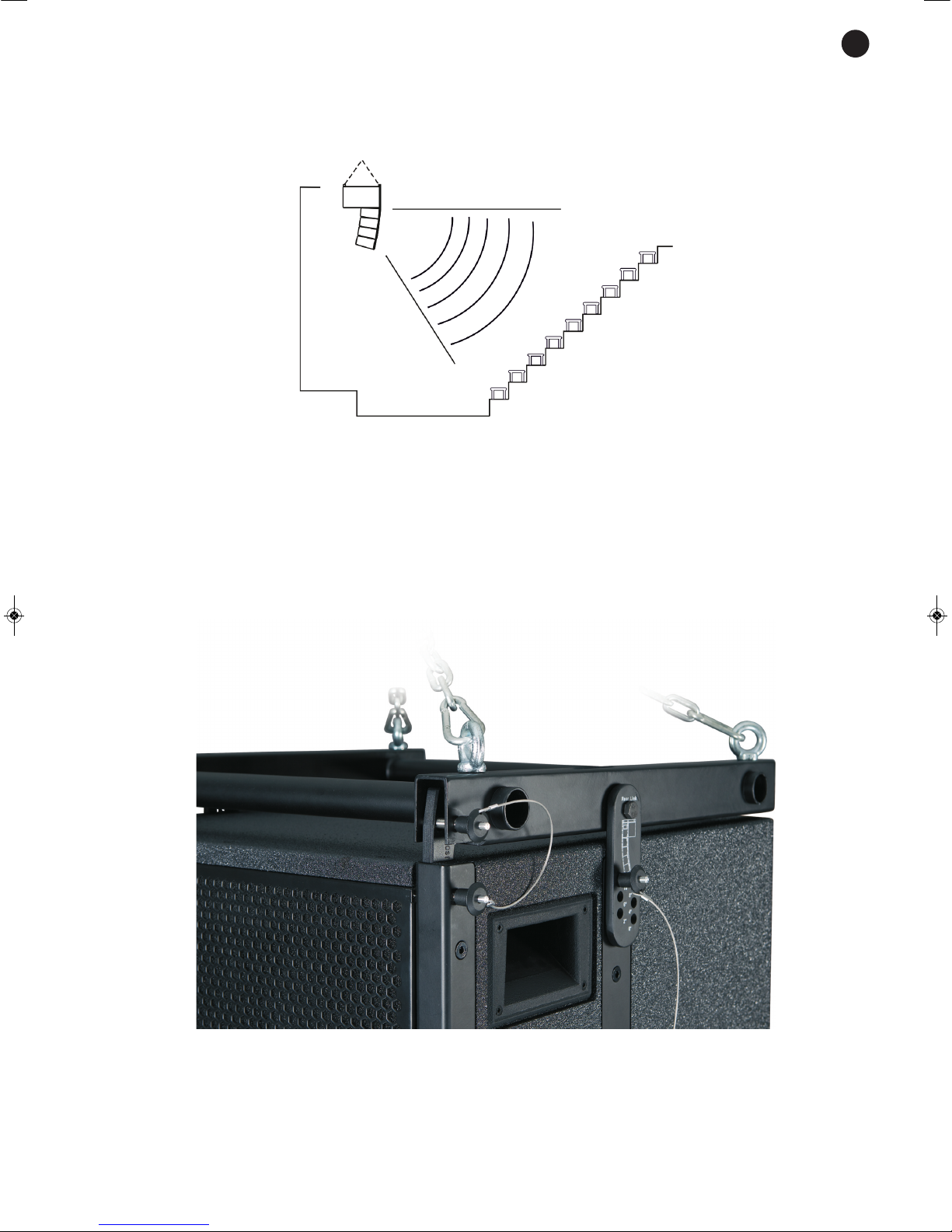
INSTALLATION
The line array has two installation possibilities:
1) HANGING WITH THE RIGGING
SYSTEM
The most common and suitable way is to hang it with the rigging system. To do this, position and bolt the
rigging system to the subwoofer in the following way:
- Insert the eyebolts in the rigging system using the nuts and bolts supplied as accessories.
- Insert a front link in the front of the rigging system and then attach it to the subwoofer using the quick safety
pins, as shown in the image.
- Insert a back link in the central part of the rigging system using the nuts, bolts and washers supplied as
accessories. Then, attach the subwoofer to the rigging system using the back link with the quick safety
pins, as shown in the image.
E
N
- 7-
Page 8
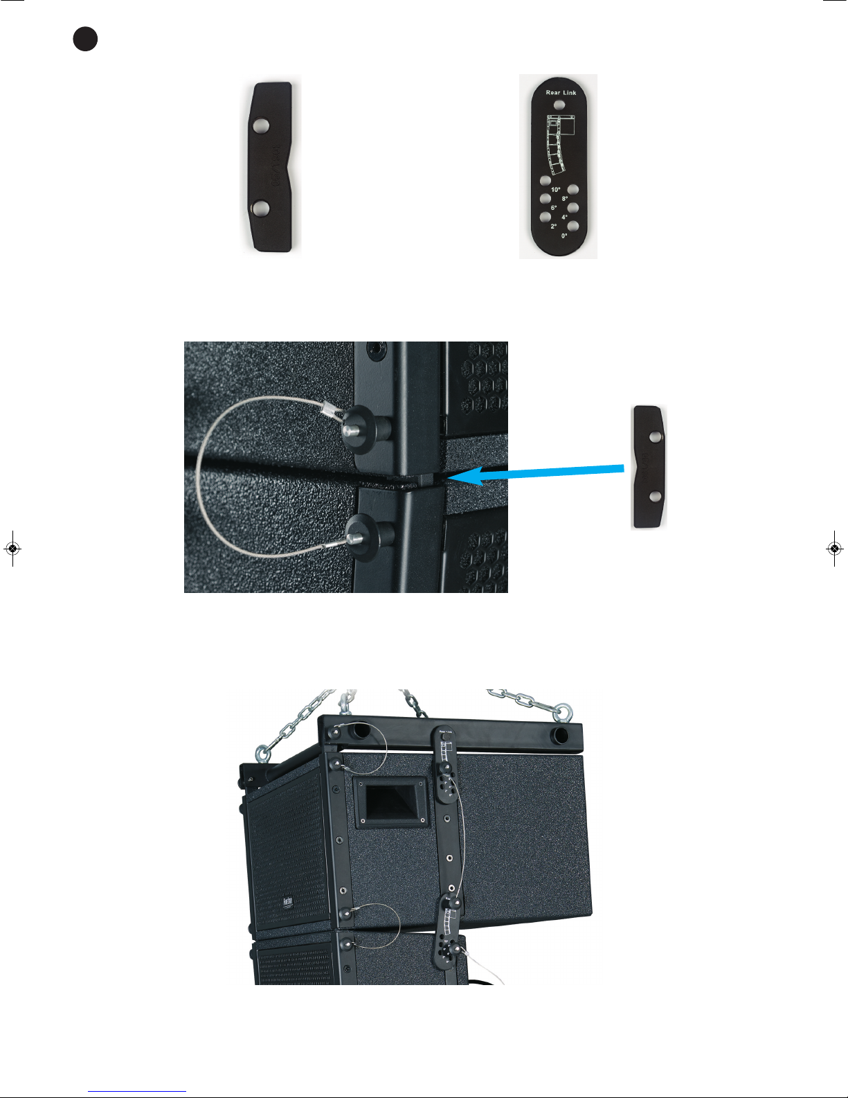
Front link Back link
Then, attach the first of the mid-treble loudspeakers to the subwoofer:
- Attach a front link to the front of the subwoofer and attach it to the mid-treble loudspeaker using the quick
safety pins as shown in the image.
Note: the front links must be placed with the convex part towards the front of the array, as shown in the
previous image.
- To fix the loudspeaker to the subwoofer completely, insert the back link and fix it using the quick safety
pins as shown in the image.
Note: the back links must be positioned on the line array in the same direction as is printed on the back link
itself. Therefore, the printing of the links will be visible on one side and not on the other.
E
N
- 8-
Page 9
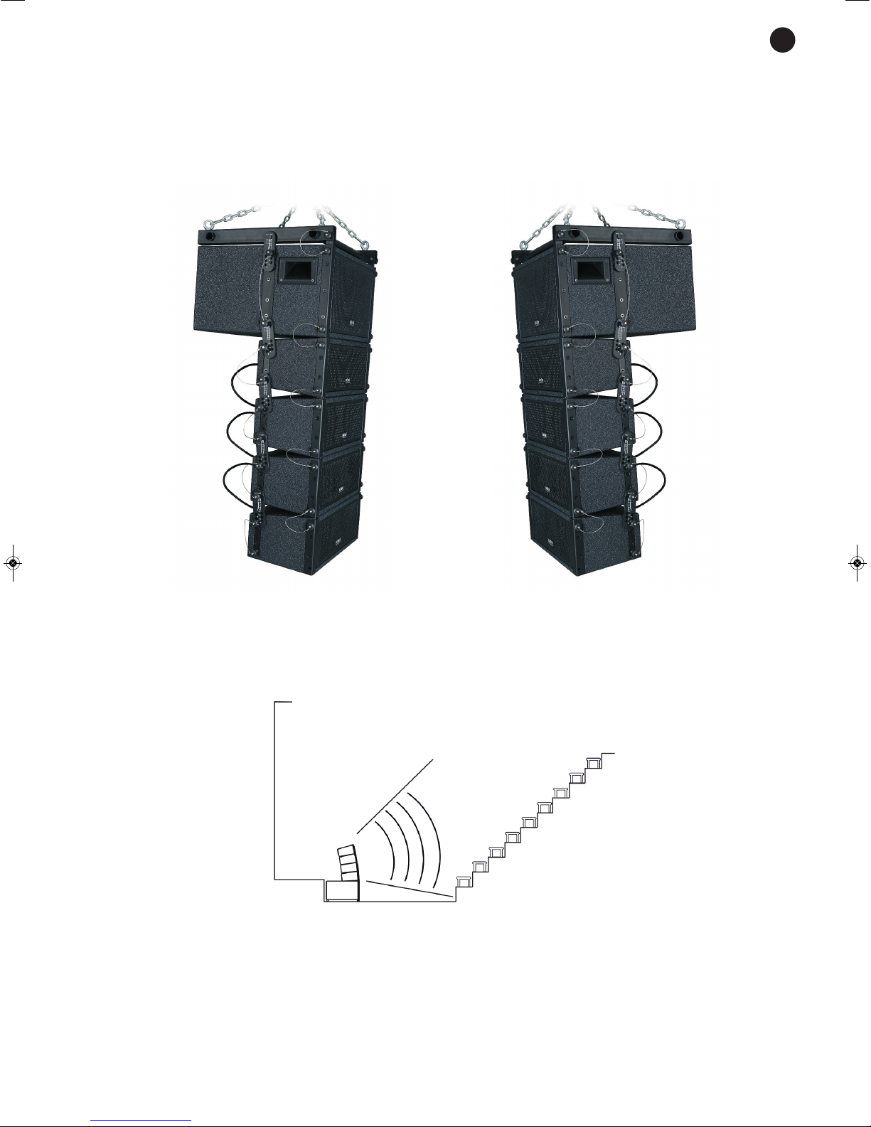
Join the rest of the mid-treble loudspeakers to each other in the same way. Join the front first, and then the
b
ack.
The tilt of the mid-treble loudspeakers can be adjusted to vary the coverage angle and achieve uniform audio
i
n the audience zone.
The tilt can be regulated with the back links between 0º and 10º in 2º at a time with respect to the previous
l
oudspeaker.
To achieve a tilt of approximately 5º from the first loudspeaker to the subwoofer and up to a maximum of 10º
between the mid-treble loudspeakers. In other words, to achieve a maximum tilt of 35º.
2) FLOOR
The line array can also be assembled on the floor using the subwoofer as a base and the mid-treble
loudspeakers on top. This is the easiest way to set them up and the most suitable if you do not have any way
of hanging them.
To connect the subwoofer and the loudspeakers together you have to follow the same procedure as before.
Use the front and back links in the same way to join the subwoofer and the mid-treble loudspeakers. The
loudspeaker tilt can be regulated to vary the coverage angle between 0º and 10º in 2º at a time.
- 9-
E
N
Page 10
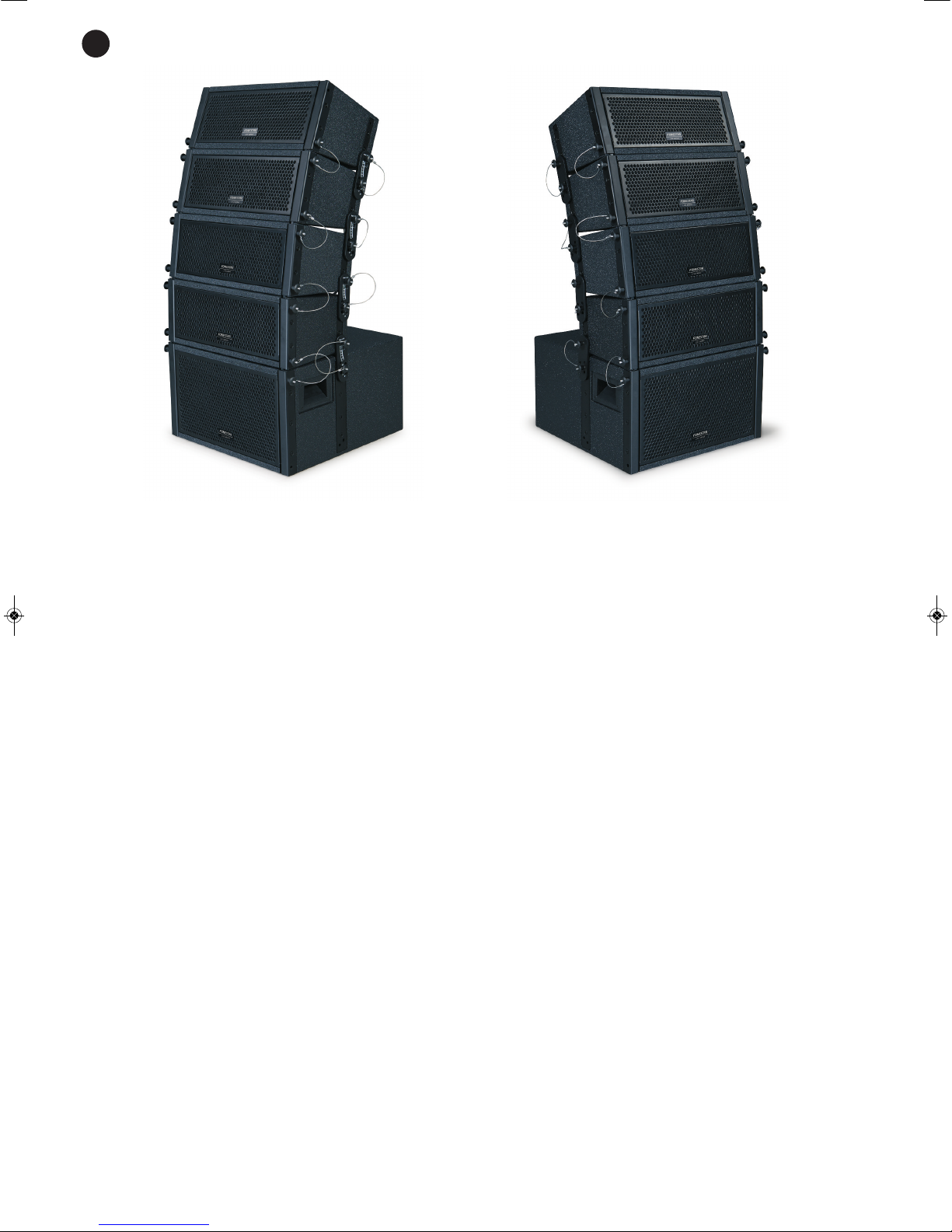
Note: the front links must be placed with the convex part towards the front of the array. the back links must
be positioned on the line array in the same direction as is printed on the back link itself. Therefore, the
printing of the links will be visible on one side and not on the other.
- 10 -
E
N
Page 11
TECHNICAL SPECIFICATIONS
ARRAY-530
CHARACTERISTICS Compact LINE ARRAY system.
Subwoofer and 4 mid-treble loudspeakers with adjustable tilt from 0 to 10º
in steps of 2º.
Manufactured in reinforced wood and finished in highly resistant granulated
p
aint.
Suspension system and accessories.
For fixed or mobile installations.
High quality audio and components.
Easily transported and installed.
POWER 1000 W maximum, 500 W RMS
Subwoofer: 500 W maximum, 250 W RMS
Loudspeakers: 140 W maximum, 70 W RMS
LOUDSPEAKERS Subwoofer: 2 x 8" woofer: 50 mm coil and 140 mm ferrite magnet
Loudspeakers: 2 x 5" mids: 25 mm coil and 80 mm ferrite magnet and 1 x
3" tweeter
RESPONSE Subwoofer: 40-200 Hz ±5 dB
Loudspeakers: 50-20 000 Hz ±3 dB
IMPEDANCE Subwoofer: 4 Ω
Loudspeakers: 16 Ω
SENSITIVITY Subwoofer: 90 dB at 1 W/1 m
Loudspeakers: 86 dB at 1 W/1 m
DISPERSION Loudspeakers: 90º H x 25º to 90º V (depending on the tilt angle)
CONNECTORS Subwoofer: 2 x 4-contact speaker connector (1+, 1-) for filtered signal
Loudspeakers: 2 x 4-contact speaker connector (1+, 1-) in each speaker,
the interconnection of all 4 speakers equals 4 Ω
SUSPENSION POINTS Upper mount with 4 eyebolts
CROSSOVER Loudspeakers: Passive, 2 ways, cutoff frequency 4000 Hz
DIMENSIONS Subwoofer: 480 x 280 x 480 mm depth
Loudspeakers: 480 x 185 x 230 mm depth
ACCESSORIES Rigging system with upper mount, front and back links, and quick use
safety pins included.
3 cables for interconnecting the loudspeakers, 2 x speaker connectors
- 11 -
E
N
Page 12

WARRANTY
This product has been tested and has passed the corresponding quality control prior to being put on the market.
FONESTAR guarantees the suitability of the product for its specified use during a period of 2 years from the delivery date
and commits itself to repair or substitute the goods as expressed in the Spanish law “La Ley General para la Defensa de los
Consumidores y Usuarios, Real Decreto Legislativo 1/2007 16 Noviembre”.
The lack of conformity in the first six months after purchase, due to a manufacturing defect, will be rectified with no more than
showing the proof of purchase. After six months FONESTAR reserves the right to demand proof of the product being sold
with that problem.
This warranty does not include damage produced by: inappropriate use or negligence, accidents, worn out parts due to use,
breakages, burns, spilt liquids or other substances, excessive humidity, battery deterioration and internal manipulation of the
device, the software or its components by unauthorized persons, and in general any use that is unrelated to the nature and
purpose of the product.
If any service is needed during the warranty period because of lack of conformity, please contact the business or distributor
where the product was purchased in no more than 2 months after being conscious of the problem. It is only necessary to
contact FONESTAR if it is impossible or imposes an undue burden for them to solve it.
To benefit from this warranty it is necessary to show the proof of purchase with the date clearly visible, with no corrections
or crossing out.
This document adds information, and never decreases the consumers’ rights, which in all cases are protected by the Spanish
law “La Ley General para la Defensa de los Consumidores y Usuarios, Real Decreto Legislativo 1/2007 16 Noviembre”.
FONESTAR is a member of ECOEMBALAJES ESPAÑA, S.A. “ECOEMBES”, with number 03497 and all our products carry the symbol,
backed by our membership and subscription to the above mentioned organization with the recycling and subsequent management of
our packaging.
FONESTAR S.A. - NIF A28780443 - Polígono Trascueto - 39600 Revilla de Camargo, Cantabria, (España)
www.fonestar.com
 Loading...