

Fonderie SIME FORMAT TECHNYL Series, FORMAT 25 OF, FORMAT 30 BF, FORMAT 30 OF, FORMAT 25 BF Installer's Instructions
Page 1

CONTENTS
1 DESCRIPTION OF THE BOILER . . . . . . . . . . . . . . . . . . . . . . . . . . . . . . . . . . . . . . . . . . . . . . . . . . . . . . . . . . . . . . . . . . . . . . . . pag. 73
2 INSTALLATION . . . . . . . . . . . . . . . . . . . . . . . . . . . . . . . . . . . . . . . . . . . . . . . . . . . . . . . . . . . . . . . . . . . . . . . . . . . . . . . . . . . . . . . pag. 76
3 CHARACTERISTICS . . . . . . . . . . . . . . . . . . . . . . . . . . . . . . . . . . . . . . . . . . . . . . . . . . . . . . . . . . . . . . . . . . . . . . . . . . . . . . . . . . . pag. 84
4 USE AND MAINTENANCE . . . . . . . . . . . . . . . . . . . . . . . . . . . . . . . . . . . . . . . . . . . . . . . . . . . . . . . . . . . . . . . . . . . . . . . . . . . . pag. 88
INSTALLER INSTRUCTIONS
IMPORTANT
When carrying out commissioning of the boiler, you are highly recommended to perform the following checks:
– Make sure that there are no liquids or inflammable materials in the immediate vicinity of the boiler.
– Make sure that the electrical connections have been made correctly and that the earth wire is connected to a
good earthing system.
– Open the gas tap and check the soundness of the connections, including that of the burner.
– Make sure that the boiler is set for operation for the type of gas supplied.
– Check that the flue pipe for the outlet of the products of the combustion is unobstructed and has been pro-
perly installed.
– Make sure that any shutoff valves are open.
– Make sure that the system is charged with water and is thoroughly vented.
–
Check that the circulating pump is not locked (CAUTION: Remember to release the pump coupled with the control
panel, if necessary, to protect the electronic control card).
– Purge the system, bleeding off the air present in the gas pipe by operating the pressure relief valve on the gas
valve inlet.
FORMAT TECHNYL - ENGLISH
FONDERIE SIME S.p.A. of Via Garbo 27 - Legnago (VR) - Italy declares that its hot water boilers, which bear the CE mark under
Gas Directive 90/396/CEE and are fitted with a safety thermostat calibrated to a maximum of 110°C, are not subject to application of PED Directive 97/23/CEE as they meet the requirements of article 1 paragraph 3.6 of the Directive.
Page 2
1.1 INTRODUCTION
“FORMAT” boilers are gas-fired thermal
appliances for central heating and domestic
hot water production, designed and manufactured to satisfy the needs of multiple
dwelling and modern plant requirements.
They comply with the european directives
90/396/CEE, 89/336/CEE, 73/23/CEE,
92/42/CEE and with the european specifications EN 297 - EN 483.
These appliances can be fired by natural
gas (methane) and butane gas (G30) or
propane gas (G31).
This booklet provides the instructions for
the following boiler models:
– “FORMAT 25 OF - 30 OF”
with electronic ignition and modulation,
natural draught.
– “FORMAT 25 BF - 30 BF”
with electronic ignition and modulation,
room sealed forced-draught.
The instructions given in this manual are
provided to ensure proper installation and
perfect operation of the appliance
73
1 DESCRIPTION OF THE BOILER
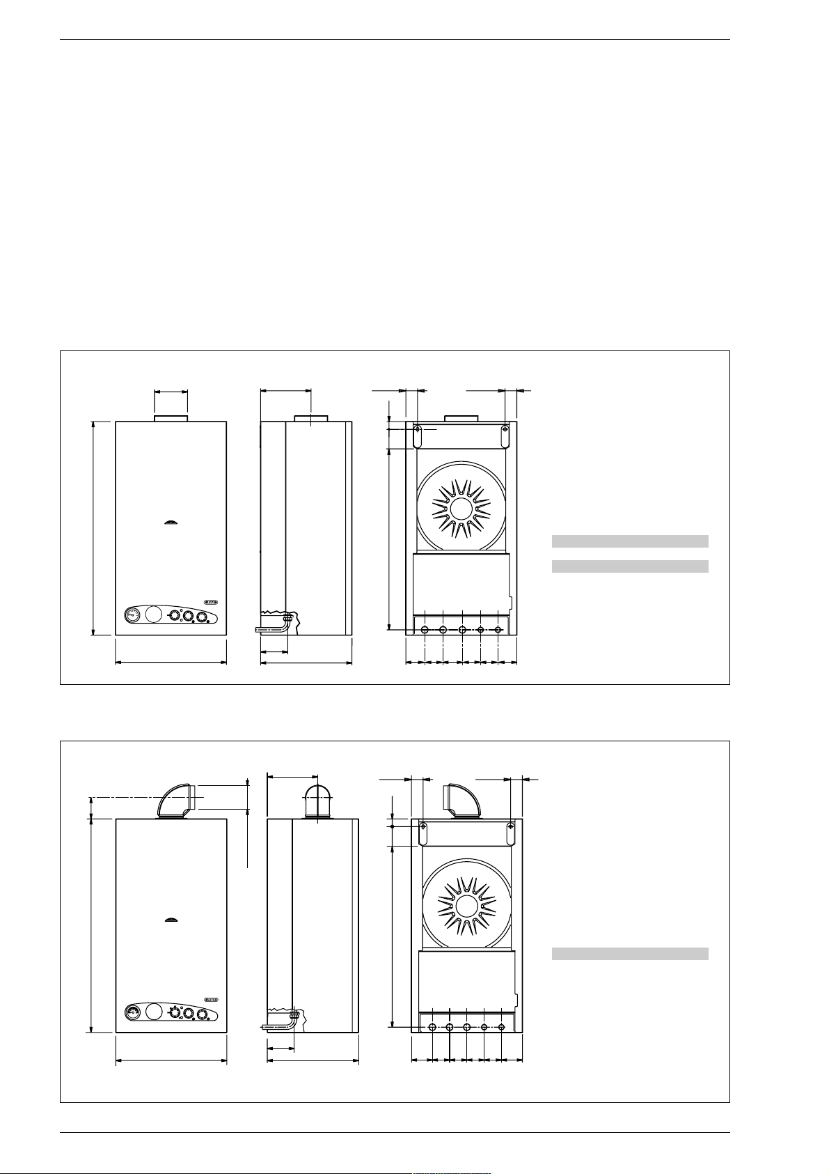
1.2 DIMENSIONS
1.2.1 “FORMAT 25 OF - 30 OF”
1.2.2 “FORMAT 25 BF - 30 BF”
L
865
D
205
47,5
47,5
31
110
370
=
=
70
70
70
70
R
M
G
E
U
732,5
80
Fig. 1
370
110
205
47,5
47,5
ø 100/60
86,5
865
L
732,5
=
=
70
707070
R
MGE
U
31
80
Fig. 1/a
R C.H. return 3/4”
M C.H. flow 3/4”
G Gas connection 3/4”
E D.H.W. inlet 1/2”
U D.H.W. outlet 1/2”
25 30
L mm 450 500
D mm 130 150
R C.H. return 3/4”
M C.H. flow 3/4”
G Gas connection 3/4”
E D.H.W. inlet 1/2”
U D.H.W. outlet 1/2”
25 30
L mm 450 500
Page 3

74
1.3 TECHNICAL FEATURES
* The gas consumptions refer to the calorific value at standard conditions at 15°C - 1013 mbar.
** Differential measure between the pressure upstream of the gas valve and the depression in the room sealed
25 OF 30 OF 25 BF 30 BF
Heat output
Nominal kW 23.3 28.6 23.3 29.0
kcal/h 20,000 24,600 20,000 24,900
Minimum kW 9.3 11.7 9.3 11.5
kcal/h 8,000 10,100 8,000 9,900
D.H.W. heat output
Nominal kW 23.3 28.6 23.3 29.0
Heat input
Nominal kW 25.8 31.6 25.8 31.6
Minimum kW 10.8 13.5 10.8 13.5
Water content l 2.4 2.4 3.4 3.4
Adsorbed power consumption W 105 110 150 160
Electrical protection grade
IP 44 44 44 44
Maximum water head bar 3333
Maximum temperature °C 95 95 95 95
Expansion vessel
Water content l 7 10 7 10
Preloading pressure bar 1111
CH. setting range °C 40÷80 40÷80 40÷80 40÷80
D.H.W. setting range °C 40÷60 40÷60 40÷60 40÷60
D.H.W. flow rate (EN 625) l/min 10.5 12.7 10.5 12.7
Continuous D.H.W. flow rate ∆t 30°C l/min 11.1 13.6 11.1 13.8
Minimum D.H.W. flow rate l/min 2222
D.H.W pressure
Minimum bar 0.5 0.5 0.5 0.5
Maximum bar 7777
Smokes temperature °C 119 120 135 150
Smokes flow gr/s 21.0 22.5 19.0 20.3
Category II2H3+ II2H3+ II2H3+ II2H3+
Type B11BS B11BS
B22-C12-C32-C42-C52 C12-C32-C42-C52
Weight kg 35 41 43 49
Main burner nozzle
Quantity n° 13 15 13 15
Methane ø mm 1.30 1.30 1.30 1.30
G30 - G31 ø mm 0.75 0.77 0.75 0.76
Gas consumption *
Methane m3st/h 2.72 3.34 2.72 3.34
Butane (G30) kg/h 2.02 2.48 2.02 2.48
Propane (G31) kg/h 1.99 2.40 1.99 2.40
Burner gas pressure
Methane mbar 2÷9 2÷10.5 2÷9.6 2.3÷11.1**
Butane (G30) mbar 5÷27 5.2÷27.9 5÷27 5.5÷26.8**
Propane (G31) mbar 5÷35 6.9÷35.5 5÷35 6.9÷34.9**
Gas supply pressure
Methane mbar 20 20 20 20
Butane (G30) mbar 30 30 30 30
Propane (G31) mbar 37 37 37 37
Page 4
7
3
2
1
13
10
11
12
6
5
14
4
15
8
7
5
4
6
3
2
1
10
9
11
12
15
FORMAT OF
FORMAT BF
“30” model
75
2
3
4
22
U
21
17
19 18
13
15
12
16
6
5
14
10
9
11
8
7
1
20
EG MR
23
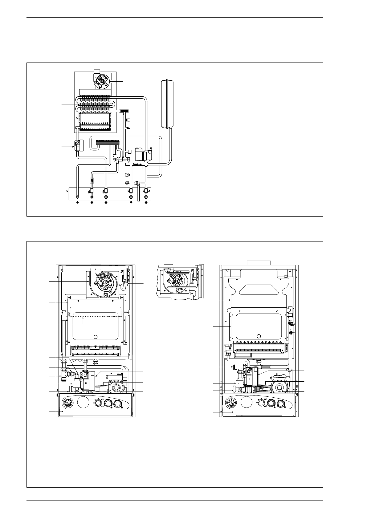
1.4 FUNCTIONAL DIAGRAM
Fig. 2
KEY
1 Fan (vers. “BF”)
2 Water-gas exchanger
3 Combustion chamber
4 Gas valve
5 D.H.W. exchanger
6 Divertor valve with charging
7 NTC sensor
8 100°C safety stat
9 Air relief valve
10 Circulation pump
11 Expansion vessel
12 Safety valve
13 Boiler discharge
14 Flowmeter
15 Thermomanometer
16 Automatic by-pass
17 D.H.W.filter
18 C.H. return cock (optional)
19 C.H. flow cock (optional)
20 D.H.W. cock (optional)
21 Gas cock (optional)
22 Fixing jig
23 C.H. water filter
1.5 MAIN COMPONENTS
Fig. 3
KEY
1 Control panel
2 Divertor valve
3 Flowmeter
4
100°C safety stat
5 Water-gas exchager
6 C.H. sensor (SM)
7 Combustion chamber
8 Fan (vers. “BF”)
9 Smoke pressure switch (vers. “BF”)
10 Gas valve
11 D.H.W. exchager
12 Circulating pump
13 Smoke chamber (vers. “OF”)
14 Smoke stat (vers. “OF”)
15 C.H. water filter
Page 5
The boiler must be installed in a fixed location and only by specialized and qualified
firms in compliance with all instructions
contained in this manual.
Furthermore, the installation must be in
accordance with current standards and
regulations.
2.1 VENTILATION OF
BOILER ROOM
The “25 OF - 30 OF”
version boilers must
be installed in adequately ventilated domestic rooms. It is essential that in rooms
where the boiler are installed at least as
much air can arrive as required by normal
combustion of the gas consumed by the
various appliances.
Consequently, it is necessary to make openings in the walls for the air inlet into the
rooms. These openings must meet the following requirements:
– have a total free section of at least 6
cm2for every kW of heat input, with a
minimum of 100 cm2;
– They must be located as close as possi-
ble to floor level, not prone to obstruction and protected by a grid which does
not reduce the effective section required
for the passage of air.
The “25 BF - 30 BF” version boilers may
instead be installed, without any constraints regarding location or supply of air
for combustion, in any domestic rooms.
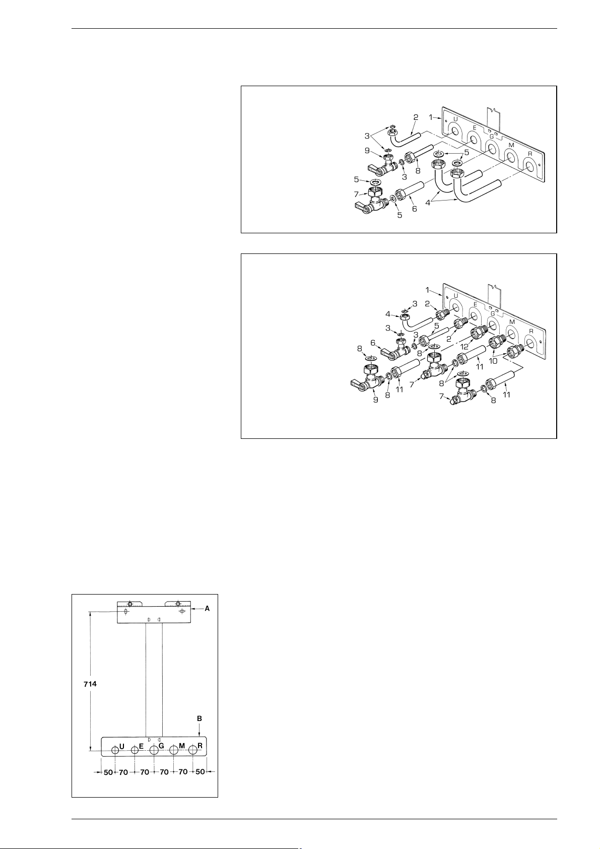
2.2 INSTALLATION PLATE
To mount the installation plate supplied as
an optional extra (kit code 8075407), follow
the instructions written below (fig. 4):
– Fix the connecting sheet to plate (A) and
lower plate (B).
– With the template complete, fix plate (A)
to the wall using the two boiler support
screws.
– Check that plate (B) is perfectly horizon-
tal using a spirit level.
– Connect the bends or connecting valves
supplied in the optional kit to the system
pipes.
2.2.1 Fitting the pipe elbows (optional)
To fit the connecting elbows supplied in kit
code 8075418, follow the instructions
reported in fig. 5.
2.2.2 Fitting isolating valves (optional)
To fit the isolating valves, supplied in kit code
8091806, follow the instructions mentioned in fig. 6.
2.2.3 Replacement wall kit
for other makes (optional)
The kit code 8093900 is supplied complete with mounting instructions.
2.3 CONNECTING UP SYSTEM
Before proceeding to connect up the boiler,
you are recommended to make the air circulating in the piping in order to eliminate
any foreign bodies that might be detrimental to the operating efficiency of the appliance.
The discharge pipe of the safety valve
must be connected to a collector funnel
for channelling away any discharge if the
safety valve goes into action.
If the heating system is on a higher floor
than the boiler, install the on/off taps supplied in kit code 8091806 on the heating
system delivery/return pipes.
The gas connection must be made using
seamless steel pipe (Mannesmann type),
galvanized and with threaded joints provided with gaskets, excluding three-piece connections, except for initial and end connections. Where the piping has to pass through
walls, a suitable insulating sleeve must be
provided. When sizing gas piping, from the
meter to the boiler, take into account both
the volume flow rates (consumption) in
m
3
/h and the relative density of the gas in
question.
The sections of the piping making up the
system must be such as to guarantee a
supply of gas sufficient to cover the maximum demand, limiting pressure loss
between the gas meter and any apparatus
being used to not greater than:
–
1.0 mbar for family II gases (natural gas);
– 2.0 mbar for family III gases (butane or
propane).
An adhesive data plate is sticked inside the
front panel; it contains all the technical data
identifying the boiler and the type of gas for
which the boiler is arranged.
76
2 INSTALLATION
Fig. 4
KEY
1 Fixing jig
2 Elbow 1/2”x14
3 Gasket ø 18.5/11.5
4 Elbow 3/4” x 18
5 Gasket ø 24/17
6 Copper pipe 3/4”x18
7 Gas cock 3/4” MF
8 Copper isolation valve
9 Isolation valve 1/2” MF
Fig. 5
KEY
1 Fixing jig
2 Straight coupling 1/2”x14
3 Gasket ø 18.5/11.5
4 Elbow 1/2”x14
5 Copper pipe 1/2”x14
6 Isolation valve 1/2” MF
7 Isolation valve 3/4” MF
8 Gasket ø 24/17
9 Gas cock 3/4” MF
10 Straight coupling
3/4”x18
11 Copper pipe 3/4”x18
12 Straight coupling
3/4”x18 with olive
Fig. 6
Page 6
2.3.1 Filter on the gas pipe
The gas valve is supplied ex factory with an
inlet filter, which, however, is not adequate
to entrap all the impurities in the gas or in
gas main pipes.
To prevent malfunctioning of the valve, or in
certain cases even to cut out the safety
device with which the valve is equipped,
install an adequate filter on the gas pipe.
2.4 CHARACTERISTICS
OF FEEDWATER
To prevent lime scale and damage to the
tap water exchanger, the water supplied
should have a hardness of no more than
20°F. In all cases the water used should be
tested and adequate treatment devices
should be installed. To prevent lime scale or
deposits on the primary exchanger, the
water used to supply the heating circuit
should must be treated in accordance with
UNI-CTI 8065 standards.
It is absolutely essential that the water is to
be treated in the following cases:
– very extensive system (with high con-
tents of feedwater);
– frequent addition of makeup water into
the system;
– should it be necessary to empty the
system either partially or totally.
2.5 SYSTEM FILLING
Filling of the boiler and the system is done
by the charge cock (2 fig. 7).
The charge pressure, with the system cold,
must be between 1 and 1.2 bar.
During system filling you are recommended
to keep the main switch turned OFF.
Filling must be done slowly so as to allow
any air bubbles to be bled off through the
air valves.
Should the pressure have
risen well above the limit expected,
discharge the over pressure by opening
the pressure-relief valve.
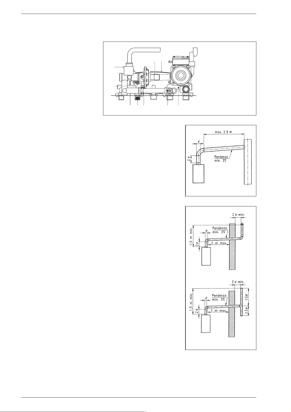
2.6 FLUE
The flue for the atmospherical expulsion of
the combustion products from natural
draught appliances must meet the following
requirements:
–
Be gas-tight to the combustion products,
waterproof and thermally insulated.
–
Be built of materials suitable for keep
resisting to normal mechanical stresses,
heat, and the action of combustion products and their possible condensates.
– Follow a vertical path and not present
any throttling throughout its entire
length.
– Be adequately insulated to prevent phe-
nomena of condensation or smokes cooling, in particular if located outside the
building or in unheated ambiences.
– Be set at an adequate distance from
combustible or easily inflammable material by means of an air gap or suitable
insulating material.
– Have beneath the mouth of the first
smoke duct a chamber for collecting
solid material and any condensate; the
height of the chamber must be at least
500 mm.
Access to the chamber must be guaranteed by means of an opening provided
with an air-tight metal door.
– Have a circular, square, or rectangular
internal cross section; in the case of
square or rectangular sections, the corners must be rounded off with a radius
of not less than 20 mm. However,
hydraulically equivalent cross sections
are allowed.
– Be equipped with a chimney-pot at the
top, which must be outside the so-called
back-flow zone, so as to prevent the formation of back-flow, which prevents free
discharge of the products of combustion
into the atmosphere.
– Be devoid of mechanical means of suc-
tion located at the top of the pipe.
– No overpressure should be present in a
chimney that passes within or close up
to inhabited rooms.
2.6.1 Connecting up flue
Fig. 8 refers to the connection of the boiler
“25 OF - 30 OF” to the flue or chimney
through smoke ducts. When making the
connection, in addition to respecting the
dimensions given, you are recommended
to use gas-tight materials capable of resisting over time mechanical stresses and
the smokes heat.
At any point along the smoke duct, the temperature of the combustion products must
be higher than the dew point. More than a
total of three changes of direction must not
be made, including the inlet connection to
the chimney/flue.
For any changes of direction use only curved pipe lengths.
Fig. 8/a shows some applications of draught terminals that ensure proper expulsion
of the combustion products, in case of
discharge through the wall.
2.7 “25 BF - 30 BF”
COAXIAL DUCT
The air inlet-smoke outlet assembly ø
60/100 is supplied in a kit code 8084805
complete with mounting instructions.
77
KEY
1 D.H.W. inlet/outlet
manifold
2 Filling cock
3 D.H.W. filter
4 Manifold by-pass
5 Water rate adjuster
6 D.H.W. exchanger
7 Microswitches
8 Flowmeter
9 Boiler discharge
Fig. 7
Fig. 8
Fig. 8/a
6
7
8
5
2
3
1
9
4
Page 7
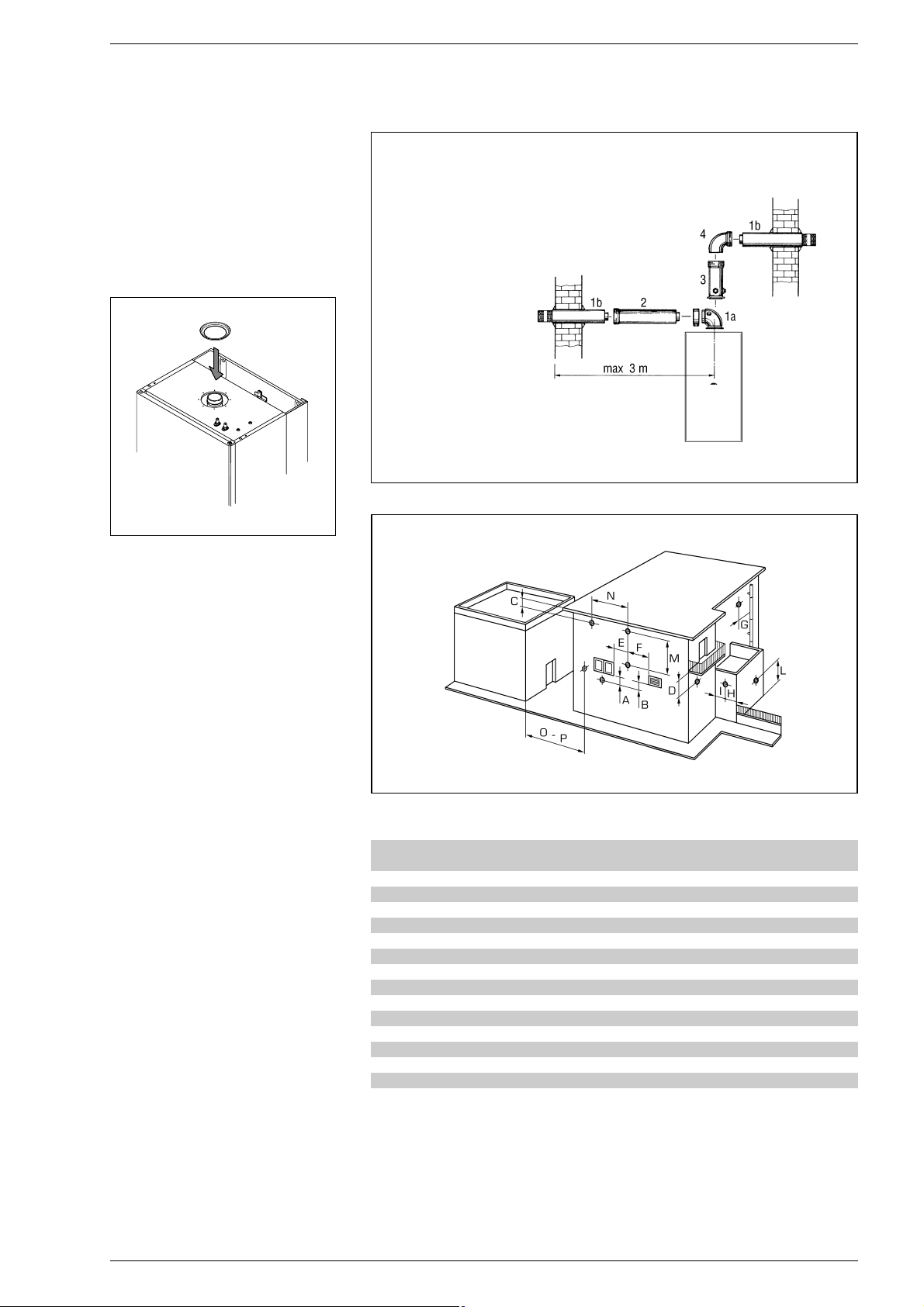
2.7.1 Installation of diaphragm
The diaphragm is normally supplied
together with boiler version “30 BF”. See
fig. 9 for positioning.
ATTENTION: Install the diaphragm only
when the length of the ø 60/100 coaxial
pipe is less than 1 m.
2.7.2 Coaxial duct accessories
The accessories to be used for this type of
installation and some of the connecting
systems that may be adopted are illustrated in fig. 10.
With the pipe bend included in the kit, the
maximum length of the piping should not
exceed 3 m.
When the vertical extension code
8086900 is used, the terminal part of the
pipe must always come out horizontally.
2.7.3 Positioning the
outlet terminals
The outlet terminals for forced-draught
appliances may be located in the external
perimeter walls of the building.
To provide some indications of possible solutions, Table 1 gives the minimum distances
to be observed, with reference to the type
of building shown in fig. 10/a.
2.7.4 Coaxial duct outlet
on the roof
The roof discharge terminal L. 1284 cannot
be shortened and when positioning the tile,
the minimum distance from the discharge
head terminal must not be less than 600
mm (fig. 11).
The accessories to be used for this type of
installation and some of the connecting
systems that may be adopted are illustrated in fig. 12.
It is possible to insert up to a maximum of
three extensions and reach a maximum
rectilinear distance of 3.7 m.
Should it be necessary to make two chan-
78
KEY
1a-b Coaxial duct kit code 8084805
2a Extension L. 1000 code 8096100
2b Extension L. 500 code 8096101
3 Vertical extension L. 200
with take-off point code 8086908
4 Supplementaty 90° elbow code 8095800
TABLE 1
Siting of terminal Appliances from 7 to 35 kW
(distances in mm)
A - below openable window 600
B - below ventilation opening 600
C - below eaves 300
D - below balcony (1) 300
E - from adjacent window 400
F - from adjacent ventilation opening 600
G - from horizontal or vertical soil or drain pipes (2) 300
H - from corner of building 300
I - from recess in building 300
L - from ground level or other treadable surface 2500
M - between two terminals set vertically 1500
N - between two terminals set horizontally 1000
O - from a surface facing without openings or terminals 2000
P - as above but with openings and terminals 3000
Fig. 10/a
Fig. 10
1)
Terminals below a practicable balcony must be located in such a way that the total path
of the smoke from its outlet point from the terminal to its outlet point from the external
perimeter of the balcony, including the height of possible railings, is not less than 2000
mm.
2) When siting terminals, where materials that may be subject to the action of the combu-
stion products are present in the vicinity, e.g., eaves, gutters and downspouts painted or
made of plastic material, projecting timberwork, etc., distances of not less than 1500 mm
must be adopted, unless adequate shielding is provided to guard these materials.
Fig. 9
IMPORTANT:
– Each additional 90° curve installed reduces the
available length by 0.90 metres.
– Each additional 45° curve installed reduces the
available length by 0.45 metres.
Page 8
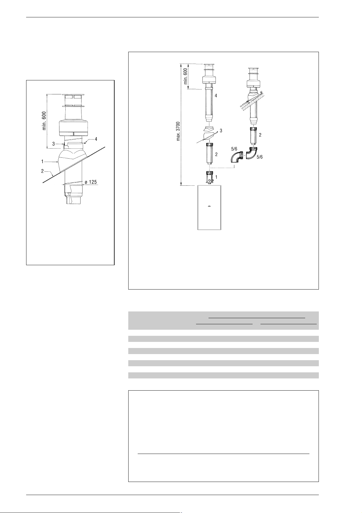
ges of direction in the pipe development,
the maximum length of the pipe must not
exceed 2 m.
2.8
“25 BF - 30 BF” SEPARATE PIPES
When installing the pipes, follow closely
the requirements of the current standards, as well as the following practical
pointers:
– With direct intake from outside, when
the pipe is longer than 1 m, you are
recommended to insulate the piping so
as to prevent formation of dew on the
outside of the piping during particularly
hard periods of the year.
– With the outlet pipe outside the building
or in cold indoor environments, insulation
is necessary to prevent burner failure in
starting.
In such cases, provide for a condensatecollector system on the piping.
– With the outlet pipe outside the building
or in cold indoor environments, insulation
is necessary to prevent burner failure in
starting.
In such cases, provide for a condensatecollector system on the piping.
The maximum overall length of the intake
and exhaust ducts depends on the head
losses of the single fittings installed
(excluding the doublers) and must not be
greater than 7.00 mm H
2
O (vers. “25”)
and 11.00 mm H2O (vers. “30”).
For head losses in the fittings, refer to
Table 2.
79
TABLE 2
Accessories ø 80 Head loss (
mm H2O)
“25” version “30” version
Inlet Outlet Roof outlet Inlet Outlet Roof outlet
90° elbow MF 0,30 0,40 – 0,30 0,50 –
45° elbow MF 0,20 0,30 – 0,20 0,40 –
Extension L. 1000 (horizontal) 0,20 0,30 – 0,20 0,40 –
Extension L. 1000 (vertical) 0,30 0,20 – 0,30 0,30 –
Outlet terminal – 0,30 – – 0,40 –
Intake terminal 0,10 – – 0,10 – –
Doubler fitting 0,20 – – 0,30 – –
Roof outlet terminal L.1390 – – 0,50 – – 0,60
Tee condensation outlet – 0,90 – – 1,10 –
Example of allowable installation calculation (“25” version) in that the sum of the head losses of the single fittings is less than 7.00 mm H
2
O:
Intake Outlet
7 meter horizontal pipe ø 80 x 0.20 1.40 –
7 meter vertical pipe ø 80 x 0.30 – 2.10
n° 2 90° elbows ø 80 x 0.30 0.60 –
n° 2 90° elbows ø 80 x 0.40 – 0.80
N° 1 terminal ø 80 0.10 0.30
Total head loss 2.10 + 3.20 = 5.3
mm H2O
With this total head loss, remove the ø 38 baffle from the intake pipe.
KEY
1 Tile with articulated joint
2 Lead panel
3 Collar
4 Locking screw
Fig. 11
Fig. 12
KEY
1 Vertical extension L. 200 with take-off point code 8086908
2a Extension L. 1000 code 8096100
2b Extension L. 500 code 8096101
3 Tile with articulation joint code 8091300
4 Roof outlet terminal L. 1284 code 8091200
5 Supplementaty 90° elbow code 8095800
6 Supplementaty 45° elbow code 8095900
Page 9
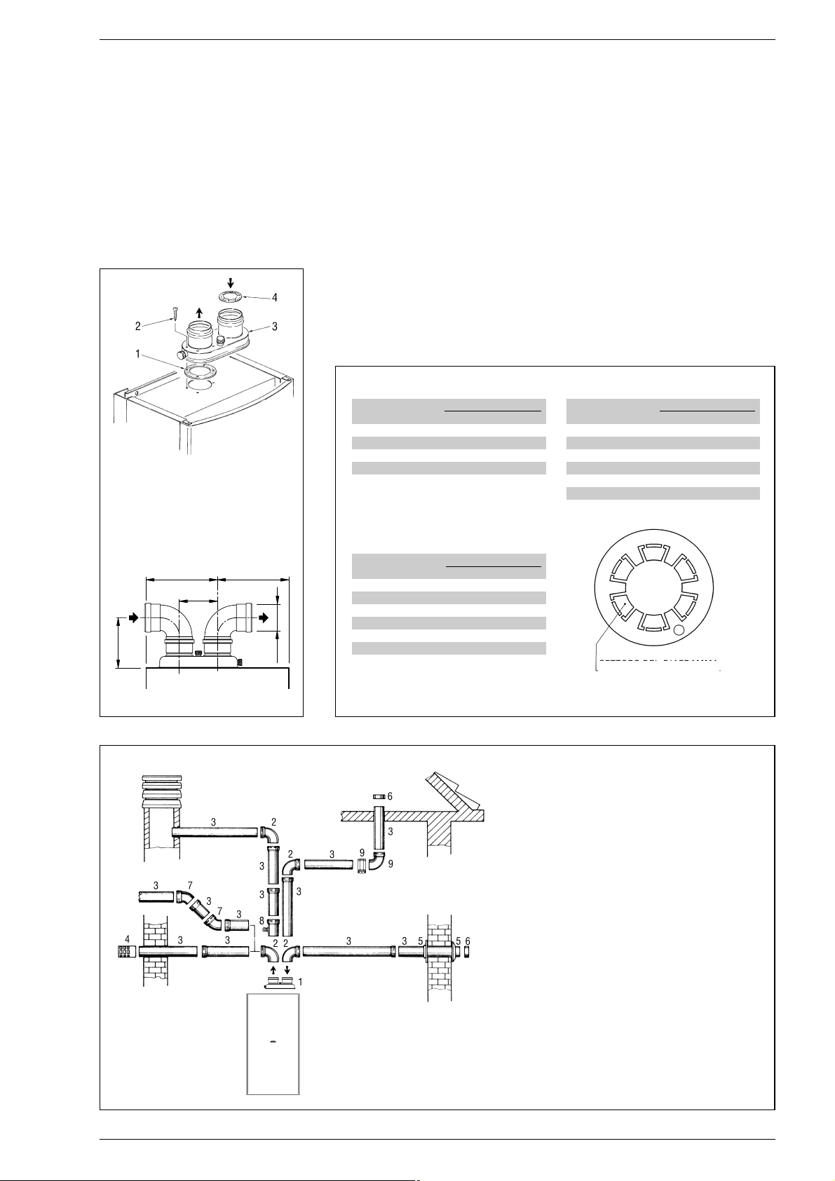
2.8.1 Separate pipe accessories
Kit code 8093000 is supplied for this purpose (fig. 13).
The sectored diaphragm is to be used
according to the maximum head loss
allowed in both pipes, as given in fig. 14.
The complete range of accessories necessary for satisfying all installation require-
ments is reported in fig. 15.
2.8.2 Separate-pipes roof outlet
The roof outlet terminal L. 1390 cannot be
shortened and when positioning the tile, the
minimum distance from the discharge head
terminal must not be less than 700 mm
(fig. 16).
The accessories to be used for this type of
installation and some of the connecting
systems that may be adopted are illustrated in fig. 17.
There is the possibility of doubling the airintake and smoke-outlet pipes and then brin-
ging them back together again so as to
obtain a concentric discharge by using the
doubler fitting (7 fig. 17).
In these cases, when assembling, recover
the silicone gasket used on the terminal
adapter (5 fig. 16), which is to be replaced
by the doubler, and insert it into the seat
made in the doubler.
For this type of discharge the sum of the
maximum rectilinear development allowed
for the pipes must not exceed 7.00 mm
H2O (“25” vers.) and 11.00 mm H2O (“30”
vers.). When calculating the lengths of pipe,
take into account the parameters given in
the Table 2.
80
Fig. 13
12 0
=
=
ø 80
16 0
KEY
1 Sponge-rubber gasket ø125/95
2 Fixing screw
3 Air-smokes flow splitting unit
with take-off point
4 Sectors of diaphragm ø 38
Fig. 14
Fig. 15
KEY
1 Air-smokes flow plitting unit
with take-off point code 8093000
2a 90° elbow MF (n° 6) code 8077410
2b Isolated 90° elbow MF code 8077408
3a Extension L. 1000 (n° 6) code 8096003
3b Isolated extension L. 1000 code 8077306
3c Extension L. 500 (n° 6) code 8096002
4 Outlet terminal code 8089501
5 Int.-est. ring kit code 8091500
6 Intake terminal code 8089500
7 45° elbow MF (n° 6) code 8077411
8 Condensation outlet L. 135 code 8092800
9 Locking junction (n° 5) code 8092700
SECTOR OF DIAPHRAGM
Sectors of diaphragm Total head loss
to remove mm H
2OPa
1 0 ÷ 2 0 ÷ 19,6
2 2 ÷ 3 19,6 ÷ 29,4
4 3 ÷ 4 29,4 ÷ 39,2
6 4 ÷ 5 39,2 ÷ 49,0
Remove diaphragm 5 ÷ 7 49,0 ÷ 68,6
“25 BF” version
Sectors of diaphragm Total head loss
to remove mm H
2OPa
1 0 ÷ 1 0 ÷ 9,8
2 1 ÷ 2 9,8 ÷ 19,6
3 2 ÷ 4 19,6 ÷ 39,2
4 4 ÷ 5 39,2 ÷ 49,0
5 5 ÷ 6 49,0 ÷ 58,8
6 6 ÷ 7 58,8 ÷ 68,6
Remove diaphragm 7 ÷ 8 68,6 ÷ 78,4
“25 BF” version B22 type
Sectors of diaphragm Total head loss
to remove mm H
2OPa
1 0 ÷ 2 0 ÷ 19,6
2 2 ÷ 3 19,6 ÷ 29,4
3 3 ÷ 4 29,4 ÷ 39,2
4 4 ÷ 5 39,2 ÷ 49,0
5 5 ÷ 6 49,0 ÷ 58,8
6 6 ÷ 7 58,8 ÷ 68,6
Remove diaphragm 7 ÷ 11 68,6 ÷ 107,8
“30 BF” version
Page 10
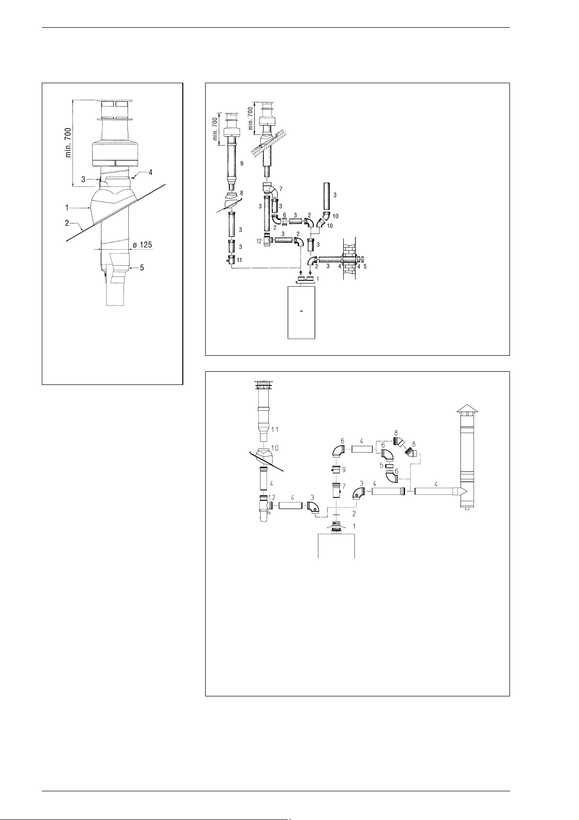
2.9 FORCED OUTLET
The “25 BF” version can also be installed as
a B22 type apparatus by assembling the
stub pipe inlet/outlet kit cod. 8089950.
The kit comes with a sector diaphgram,
instruction sheet and a label with the room
aeration warnings to be attached to the boiler casing. The sector diaphram must be
used according to the maximum load loss
allowed by the duct, as indicated in fig. 14.
The complete range of fittings required to
carry out the installation is given in fig. 18.
The maximum length of the duct is determined by the load losses of the single attached fittings (excluding the inlet/outlet
stub pipe) and should not be greater than
8.00 mm H2O.
To calculate the load loss of the individual fittings attached see Table 2.
2.10 ELECTRICAL CONNECTION
The boiler is supplied with an electric cable.
Should this require replacement, it must be
purchased exclusively from SIME.
The electric power supply to the boiler must
be 230V~50Hz single-phase through a
fused main switch, with at least 3 mm spacing between contacts.
NOTE: Device must be connected to an
efficient earthing system.
SIME declines all responsibility for injury
or damage to persons, animals or things,
resulting from the failure to provide for
proper earthing of the appliance.
2.10.1 Electric switchboard
To access the electrical panel, turn off the
power supply and then remove the front
panel and the two screws that anchor the
control panel to the sides(see point 4.7).
The panel will tilt forward at a sufficient angle
to allow access to the components.
To remove the protection, unscrew the fixing
screws and use a screwdriver to release the
upper tabs and free it from the control panel
(fig. 19).
81
Fig. 17
KEY
1 Air-smokes flow splitting unit
with take-off point code 8093000
2 a 90° elbow MF (n° 6)
code 8077410
2 b Isolated 90° elbows MF
code 8077408
3 a Extension L. 1000 (n° 6)
code 8096003
3 b Isolated extension L. 1000
code 8077306
3 c Extension L. 500 (n° 6)
code 8096002
4 Int.-est. ring kit code 8091500
5 Intake terminal code 8089500
6 Locking junction (n° 5)
code 8092700
7 Doubler fitting code 8091400
8 Tile with articulated joint
code 8091300
9 Roof outlet terminal L. 1390
code 8091201
10 45° elbow MF (n° 6) code 8077411
11 Condensation outlet L. 135
code 8092800
12 Tee condensation outlet
code 8093300
Fig. 16
Fig. 18
KEY
1 Inlet/outlet terminal
2 Sectors diaphragm
3 90° elbow MF with point
cod. 8077407
4a Extension L. 1000 (n° 6)
cod. 8096003
4b Isolated extension L. 1000
cod. 8077306
4c Extension L. 500 (n° 6)
cod. 8096002
5 Locking junction (n° 5)
cod. 8092700
6 90° elbow MF (n° 6) cod. 8077410
7 Extension L. 135 with point
cod. 8077304
8 45° elbow MF (n° 6) cod. 8077411
9 Condensation outlet L. 135
cod. 8092800
10 Tile with articulated joint
cod. 8091300
11 Roof outlet terminal L. 1390
cod. 8091201
12 Tee condensation outlet
cod. 8093300
KEY
1 Tile with articulated joint
2 Lead panel
3 Collar
4 Locking screw
5 Reducing fitting
with gasket
Page 11
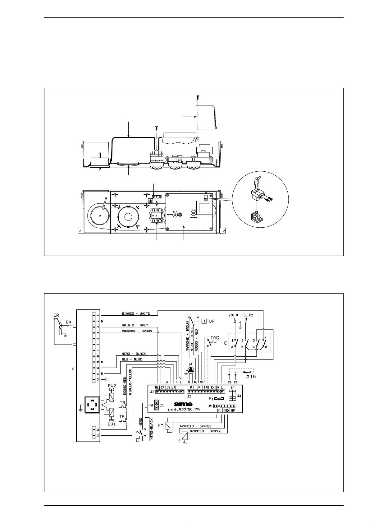
2.10.2 Room stat connection
To gain access to connector TA, remove
the control panel cover (7 fig. 9) and con-
nect the room stat to the terminals 22-23
after having removed the jumper.
The thermostat or timer-thermostat,
recommended for better room temperature control, must be class II as specified by standard EN 60730.1 (clean
contact).
82
2.10.3 “25 OF - 30 OF” wiring diagram with SIT control box
Fig. 20
KEY
EV1 Gas valve coil
EV2 Gas valve coil
EA Ignition electrode
ER Sensing electrode
A SIT 503 control box
TS 100°C safety stat
TF Smoke stat
FL Flowmeter
P Circulation pump
VP Divertor valve
TAG Antifreeze stat (optional)
C Rotary switch
TA Room stat
M Modulator
SM C.H. sensor
Note: The room stat (TA) must be connected to the terminals 22-23
12
6
7
58
3
4
KEY
1 Thermomanometer
2 Timer-programmer housing
3 Rotary switch
4 Electronic board
5 Earth faston
6 Instrument protection
7 Room stat cover
8 Room stat connector
Fig. 19
CONNECTOR SPARE
PART CODES:
J1 code 6260966
J2 code 6260962
J3 code 6260968
J5 code 6260957
Page 12
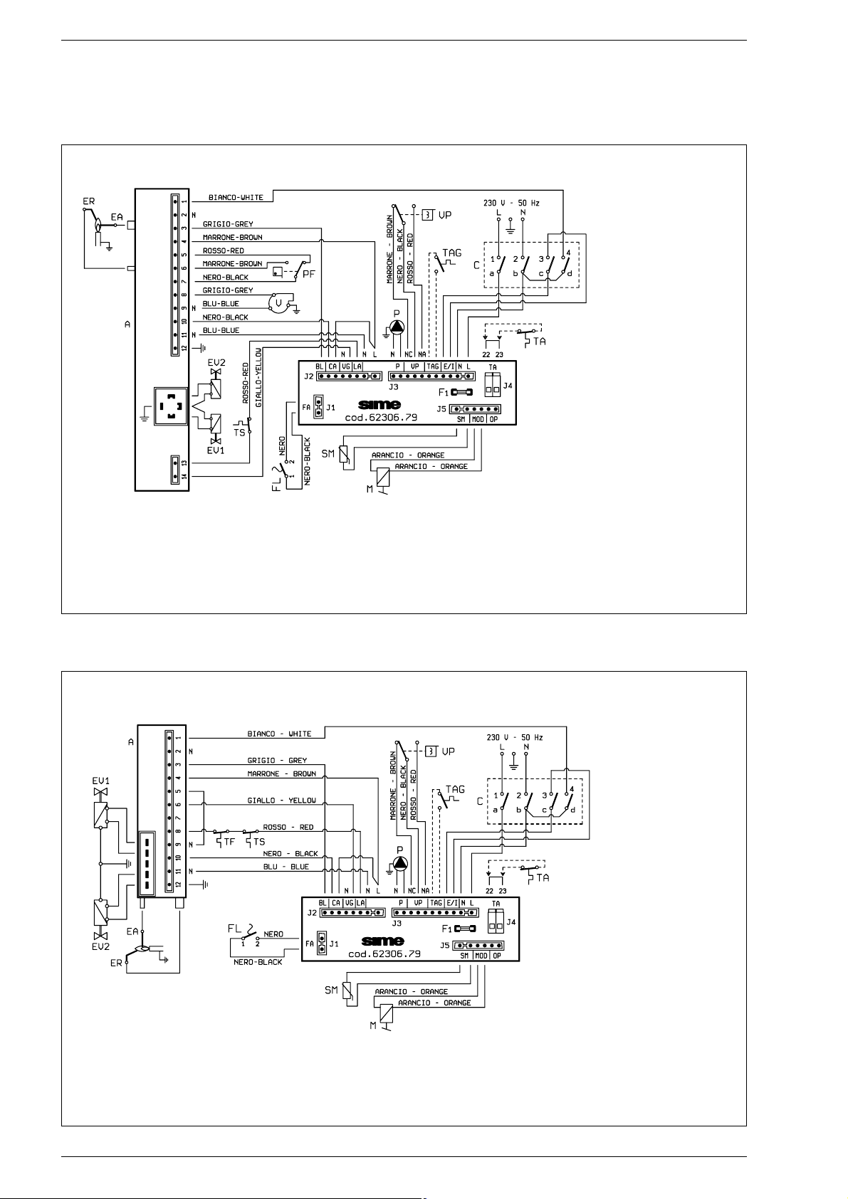
83
2.10.4 “25 BF - 30 BF” wiring diagram with SIT control box
Fig. 20/a
KEY
EV1 Gas valve coil
EV2 Gas valve coil
EA Ignition electrode
ER Sensing electrode
A SIT 503 control box
TS 100°C safety stat
PF Smoke pressure switch
VFan
FL Flowmeter
P Circulation pump
VP Diverto valve
TAG Antifreeze stat (optional)
C Rotary switch
TA Room stat
M Modulator
SM C.H. sensor
Note: The room stat (TA) must be connected to the terminals 22-23
2.10.5 “25 OF - 30 OF” wiring diagram with HONEYWELL control box
Fig. 20/b
KEY
EV1 Gas valve coil
EV2 Gas valve coil
EA Ignition electrode
ER Sensing electrode
A HONEYWELL S4565CF control box
TS 100°C safety stat
TF Smoke stat
FL Flowmeter
P Circulation pump
VP Divertor valve
TAG Antifreeze stat (optional)
C Rotary switch
TA Room stat
M Modulator
SM C.H. sensor
Note: The room stat (TA) must be connected to the terminals 22-23
CONNECTOR SPARE
PART CODES:
J1 code 6260956
J2 code 6260961
J3 code 6260968
J5 code 6260964
CONNECTOR SPARE
PART CODES:
J1 code 6260966
J2 code 6260960
J3 code 6260968
J5 code 6260957
Page 13
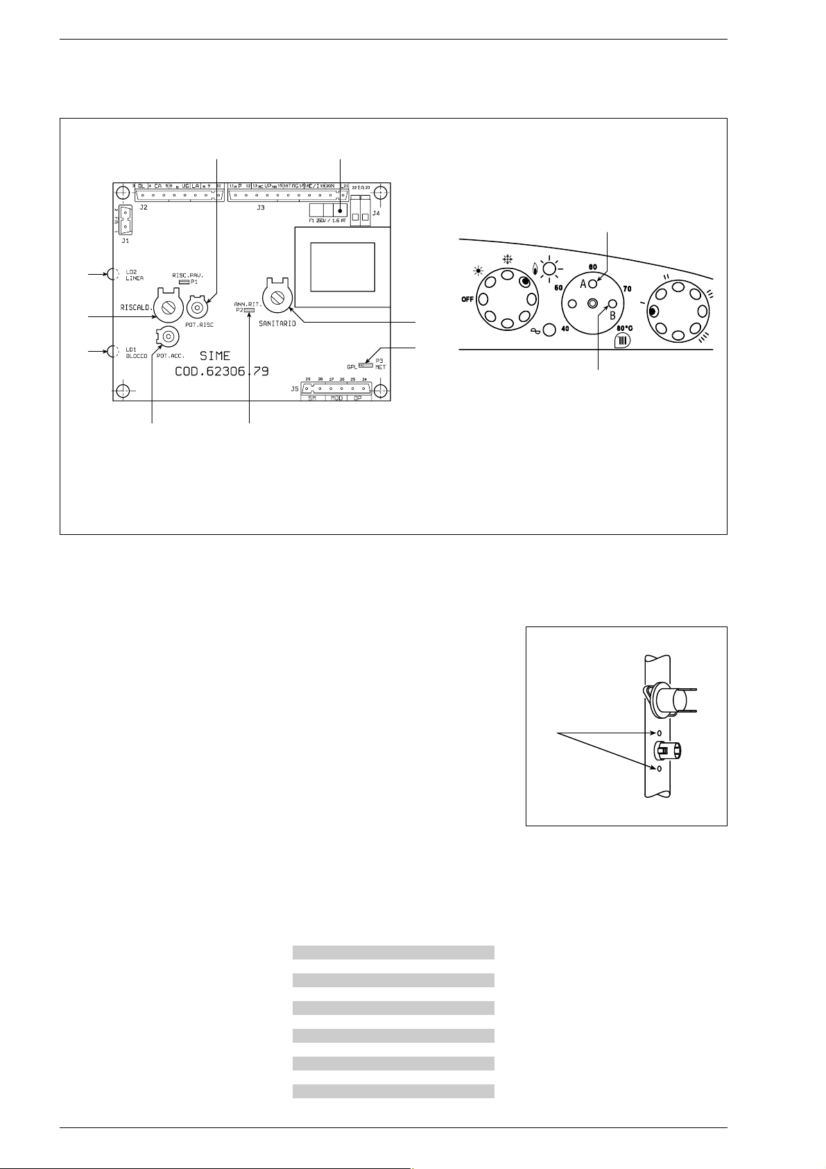
3.1 ELECTRONIC BOARD
The electronic boards are manufactured in
compliance with the EEC 73/23 low-voltage
directives. They are supplied with 230V and,
through a built-in transformer, send a voltage of 24V to the following components:
modulator, C.H. sensor and time programmer. An automatic and continuous modulation system enables the boiler to adjust the
heat output to the various system requirements or the User’s needs. The electronic
components are guaranteed against a temperature range of –10 to +60°C.
3.1.1 Central heating operation
Upon demand for heating from the room
temperature stat, the circulation pump is
activated, and approximately 90 seconds
must elapse for the burner to start operating. This will happen only if the temperature
is set above the value detected by the heating sensor. The setting range is between
40 and 80°C. The heat output can be varied
according to the system needs by adjusting
the trimmer (1 fig. 21). At start-up of each
working cycle, af ter the period of slow ignition having a duration of approx. 5 sec, the
boiler will set itself at the heat output set on
the “Minimum heating pressure” trimmer.
3.1.2 D.H.W. operation
Upon demand for hot water, the boiler
starts instantaneously when the microswitch on the pressure switch valve trips. The
required power output is regulated, via
flame modulation, by the hot water sensor,
which will compare the temperature read
with the temperature set on the potentiometer. The adjustment range is between 40
and 60°C. When the heating flow sensor is
at 75°C the electronic limiter will trip and
switch-off the burner. The burner will re-ignite when the temperature falls below 2 °C.
3.1.3 Control leds
The electronic board is equipped with control
leds which show some of the possible failures
that can cause an irregular and/or improper
operation of the appliance. The leds are located on the card as indicated in fig. 21 and
marked with the following wording:
– “LD1 BLOCCO”
Red led on when control box, safety stat
and/or smoke stat trips.
– “LD2 LINEA”
Green led off when there is no tension
present.
3.1.4 Devices available
on the electronic board
The electronic board is equipped with the
following devices:
– “POT. RISC.” trimmer (1 fig. 21)
Sets the maximum heating power value.
To increase the value turn the trimmer
clockwise; to reduce the value turn the
trimmer anticlockwise.
– “POT. ACC.” trimmer (6 fig. 21)
Trimmer to vary the pressure level upon
ignition (STEP), of the gas valve.
84
3 CHARACTERISTICS
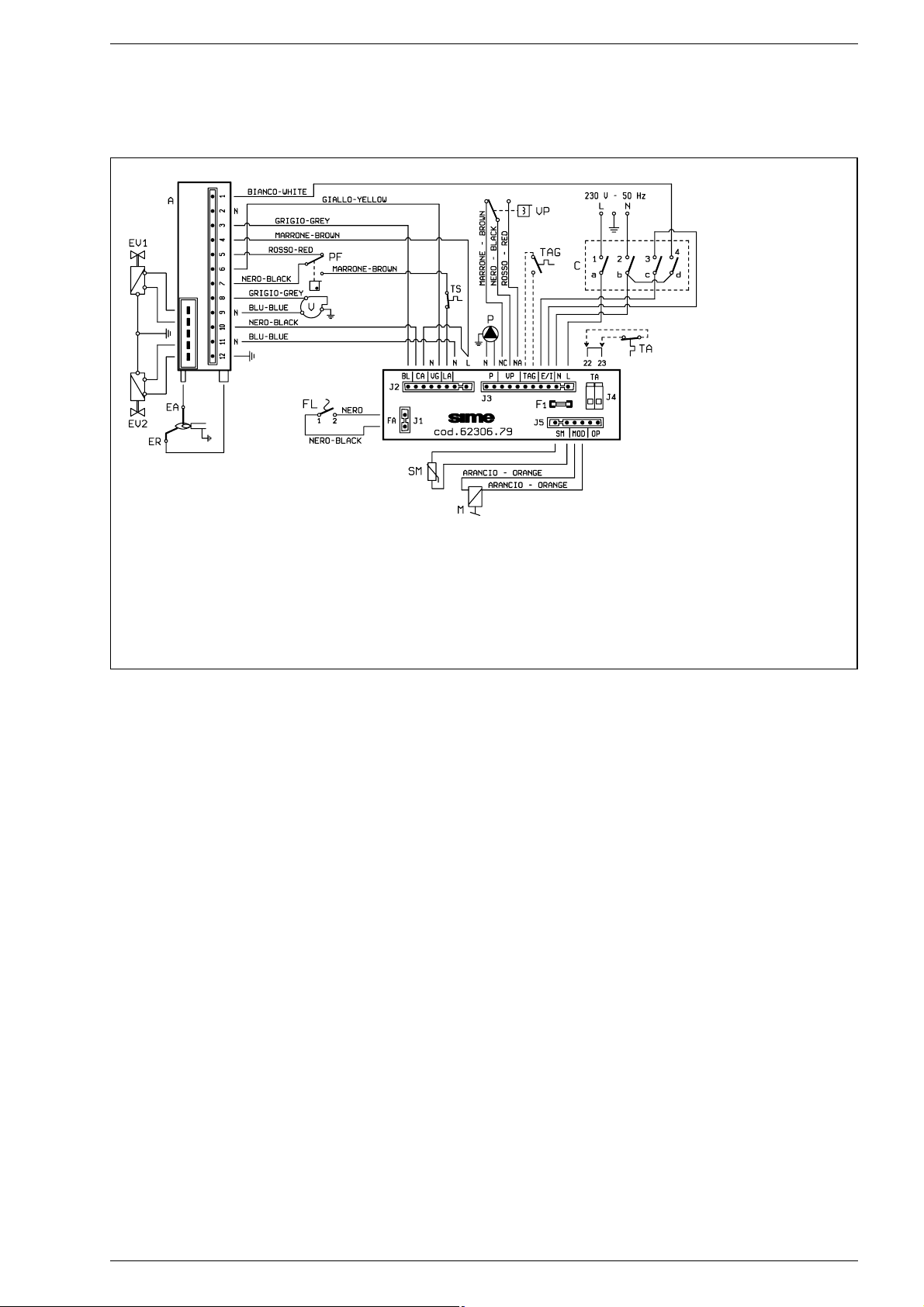
2.10.6 “25 BF - 30 BF” wiring diagram with HONEYWELL control box
Fig. 20/c
KEY
EV1 Gas valve coil
EV2 Gas valve coil
EA Ignition electrode
ER Sensing electrode
A HONEYWELL S4565CF control box
TS 100°C safety stat
PF Smoke pressure switch
VFan
FL Flowmeter
P Circulation pump
VP Divertor valve
TAG Antifreeze stat (optional)
C Rotary switch
TA Room stat
M Modulator
SM S.H. sensor
Note: The room stat (TA) must be connected to the terminals 22-23
CONNECTOR SPARE
PART CODES:
J1 code 6260956
J2 code 6260959
J3 code 6260968
J5 code 6260964
Page 14
85
According to the type of gas for which the
boiler is equipped, the trimmer must be
regulated so as to obtain a pressure of
approx. 3 mbar at the burner for methane gas and 7 mbar for butane gas (G30)
and propane gas (G31). To increase pressure, turn the trimmer clockwise; to reduce pressure, turn the trimmer counterclockwise. The slow ignition pressure level
can be set during the first 5 seconds following burner ignition. After setting the
pressure level upon ignition (STEP)
according to the type of gas, check that
the pressure for heating is still at the
value previously set.
– “GPL-MET” connector (4 fig. 21)
The connector link must be inserted on
the type of gas for which the boiler is
equipped.
– “ANN. RIT.” connector (5 fig. 21)
In the heating phase, the electronic
board is programmed to include a burner technical delay interval of approx. 2
minutes, which occurs both at system
cold starting and at subsequent re-ignitions. The aim is to overcome the problem of repeated ignitions and turning off
with very short time intervals between.
This could occur in particular in systems
presenting high head losses. At each
restart after the period of slow ignition,
the boiler will set itself for about 1 minute
at the minimum modulation pressure,
and will then move to the heating pressure value set. When the connecting link is
inserted, both the programmed technical
pause and the period of operation at
minimum pressure in the startup phase
will be cancelled. In this case, the times
elapsing between turning off and subsequent re-ignition will depend on a temperature difference of 3°C detected by the
SM sensor (heating flow sensor).
ATTENTION: It is essential that the operations described above be carried out by
authorized technical staff.
3.2 TEMPERATURE SENSOR
The “FORMAT” boilers are equipped with
sensor for detecting temperature:
The probe acts as a limit thermostat, switching-off the burner when the temperature measured is higher than 90°C; the
reset temperature is set at 80°C.
When probe (SM) has tripped, the boiler
will not function for either service. Table
3 shows the resistance values (Ω) that
are obtained on the sensor as the temperature varies.
In case of replacement, the thermistor will
have to be fitted onto the relevant clew,
located on the flow pipe (fig. 22).
3.3 CONTROL BOX
The boilers are equipped with HONEYWELL
S4565CF and/or SIT 503 electronic control and protection.
Ignition and flame detection is controlled by two electrodes located
on the burner.
These guarantee maximum safety with
intervention times, for accidental switching
off or gas failure, of within one second.
3.3.1 Operating cycle
Before igniting the boiler, use a voltmeter to
make sure that the electrical connection to
the terminal block has been made properly,
respecting the position of line and neutral,
TABLE 3
Temperature (° C) Resistance (Ω)
20 12.764
30 8.579
35 7.102
40 5.915
45 4.955
50 4.173
55 3.533
60 3.006
70 2.208
80 1.650
Fig. 22
CLEW
Fig. 21
KEY
1 “Heating output” trimmer
2 Fuse (1.6 AT)
3 D.H.W. potentiometer
4 “GPL-MET” bridge
5 “Cancel delay” bridge
6 “Ignition pressure” trimmer
7 “LD1 Block” led
8 Heating potentiometer
9 “LD2 Line” led
NOTE: To gain access to trimmers
(1) and (6), unscrew the central
heating potentiometer knob.
21
6
9
8
7
6
5
3
4
C
1
Page 15
as shown in the diagram.
Rotate the selector to summer or winter,
the red led should light up.
The boiler is now ready to start working
upon demand for heating or drawing off of
D.H.W.; a discharge current is sent to the
ignition electrode through the programmer,
and the gas valve opens at the same time.
Burner ignition normally takes place within
2 or 3 seconds.
However, it is possible for ignition failures
to occur, with consequent activation of
signal indicating that the control box has
“locked out”.
– Gas failure
The control box runs through the cycle
normally sending electric power to the
ignition electrode.
The electrode continues spark discharge
for a maximum of 10 sec.
If the burner does not ignite, the control
box “locks out”.
This may occur upon first ignition or
after long periods of boiler lay-of f when
there is air in the pipes.
It may be caused by the gas cock being
closed or by one of the valve coils having
a break in the winding, so that the valve
cannot open. The HONEYWELL valve
connector is defective.
– Ignition electrode fails to spark
In the boiler, only the gas to the burner is
seen to open. After 10 sec. the control
box “locks out”.
This may be due to a break in the wire of
the electrode or to the wire not properly
fastened to the electric terminal of the
control box; or else, the transformer has
burnt out.
– No detection of flame
The continuous spark discharge of the
electrode is noted starting from ignition
even though the burner is lit.
After 10 seconds have elapsed, the
sparks cease, the burner goes out, and
the warning light indicating equipment
“lock-out” lights up.
This occurs when the position of phase
and neutral has not been respected on
the terminal block.
There could have a break in the wire of
the sensing electrode or the electrode
itself is touching earth: the electrode is
worn out and needs replacing. The control box is defective.
When there is a sudden voltage failure, the
burner shuts out immediately; when power
supply returns, the boiler will start up again
automatically.
3.3.2 Operating cycle
At each start-up the programmers perform
a self-check which, if there is a malfunction
or parasite flame signal, disables the program start.
The programmer will not start when the air
pressure switch is not in the non-venting
position.
3.4 “25 OF - 30 OF” SMOKE
SAFETY DEVICE
This is a safety device against possible
smoke emission into the ambience (14 fig.
3). The safety device goes into action by
blocking operation of the gas valve when the
return of the smoke into the ambience is
continuous and in quantities that might constitute a danger.
The intervention of the device locks out the
appliance because the burner has not ignited. In this case, place the rotary switch to
the
( ) position
must be pressed for the
boiler to restart automatically.
Should the boiler continue to “lock out”, it will
be necessary to make a careful check on
the flue pipe, making all the necessary modifications and amendments so that it can
work properly.
3.5 “25 BF - 30 BF” SMOKE
PRESSURE SWITCH
The pressure switch is factory set at the
optimal values of 4.5 - 6 mm H
2
O (“25”
vers.) and 10-13 mm H2O (“30” vers.).
This enables the boilers operation even
with air intake and smoke outlet pipes at
the maximum limit of the length allowed (9
fig. 3).
Impurities and possible formations of
condensate, which are more likely in cold
periods of the year, could lead the pressure switch not to work and the boiler
fail to start.
3.6
NO WATER FLOW SAFETY DEVICE
The boiler has a flow switch (8 fig. 7) which
is tripped when it does not detect water
flow in the primary circuit (>400 l/h), preventing the burner from functioning.
To start the burner again, check the pressure in the system and make sure that
the pump and the flow switch are working
properly.
3.7 SYSTEM AVAILABLE HEAD
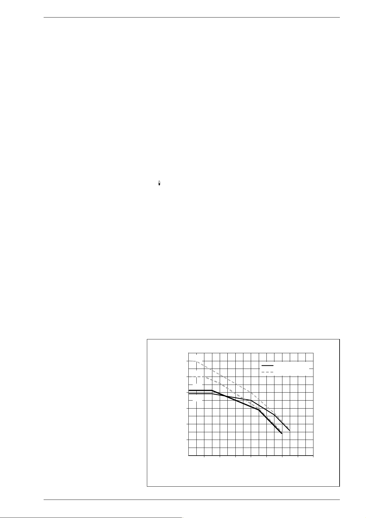
The head available for the heating plant is
shown as a function of the flow in graph in
fig. 24.
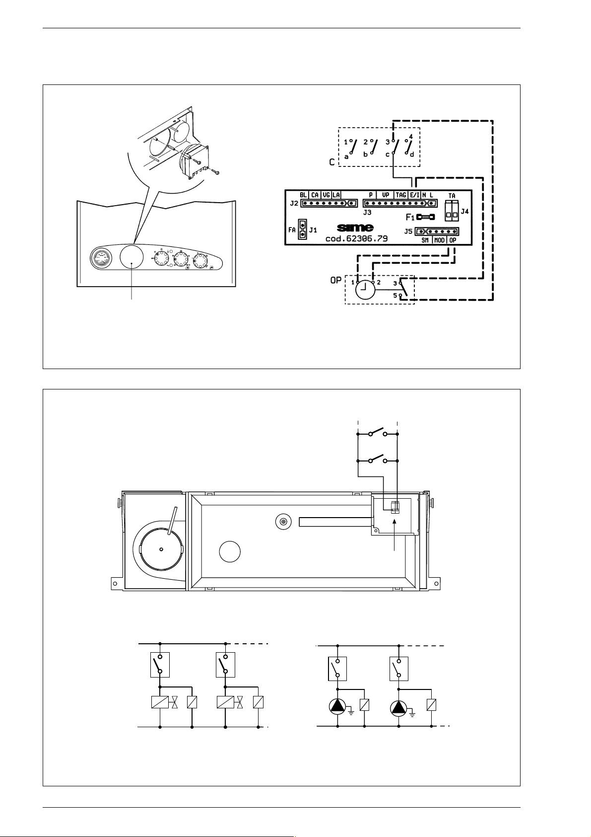
3.8 TIME PROGRAMMER (optional)
The control panel is designed to allocate a
timer-programmer, code 8092203, which
can be supplied upon request. To fit the
timer, remove the housing blanking piece
from the control panel and, with the panel
open, fit the timer to the panel using the
screws supplied therein.
Remove the faston that links the terminal 3
of the rotary switch and connect it to the
terminal 3 of the time-clock.
Connect the unit as shown in the wiring diagram (fig. 25).
3.9 MAINS ELECTRICITY
CONNECTION
Use a separate electricity supply to connect the room stats and relative zone valves or pumps.
The micro or relay contact connection is
made to terminals 22-23 (TA) of the circuit board af ter having removed the jumper (fig. 26).
86
Fig. 24
FLOW RATE (l/h)
RESIDUAL HEAD (mbar)
30
600
25
500
25
400
30
300
200
PREVALENZA RESIDUA (mbar)
con by-pass
senza by-pass
Format - Planet - Open
10 0
0
200
140012001000800600400
PORTATA (l/h)
1600
Page 16
87
KEY
OP Time programmer
C Rotary switch
Fig. 25
L
N
TA
TA
1
VZ
R
VZ1
R1
NOTA: I relé vengono impiegati solo nel caso
le valvole di zona siano prive di micro.
CR1
CR
Connettore "TA"
22 23
L
N
TA
TA1
P
R
P1
R1
CIRCUITO CON VALVOLE DI ZONA
CIRCUITO CON POMPE DI ZONA
Fig. 26
KEY
TA-TA1 Zone room stat
VZ-VZ1 Zone gas valve
R-R1 Zone relay
CR-CR1 Zone microvalve or relay contact
P-P1 Zone pump
REMOVE
“TA” connector
NOTE: The relays are only used where the zone
valves are not fitted with micros.
1. CIRCUIT WITH ZONE VALVES
2. CIRCUIT WITH ZONE PUMPS
Page 17
4.1 TEMPERATURE
ADJUSTMENT OF D.H.W.
The sistem with a potentiometer for adjusting the temperature of D.H.W. with a setting range from 40° to 60°C offers a double advantage:
1) The boiler adapts perfectly to any type of
D.H.W. system, whether the mixing
system is a mechanical or a thermostatcontrolled type.
2) The thermal output is dosed according
to the temperature required, which
means a considerable saving in fuel.
NOTE: In order to avoid any misunderstanding please remember that the value
obtained by the product of temperature
difference (in °C) between D.H.W. output
and input into the boiler by the hourly
flow rate measured on the tap, where
hot water is drawn off (l/h), cannot be
higher than the useful output developed
by the boiler. For measurements and
checks on flow rate and temperature of
D.H.W., use suitable instruments, taking
into consideration any heat dispersion
along the stretch of piping between the
boiler and the measuring point.
4.2 ADJUSTMENT OF
D.H.W. FLOW RATE
To adjust the hot water flow rate, use the
flow-rate regulator on the pressure switch
valve (5 fig. 7). Remember that the flow
rates and corresponding temperatures of
use of hot water, given in section 1.3, have
been obtained by positioning the selector of
the circulation pump on the maximum value.
Should there be any reduction in the
D.H.W. flow rate, the filter installed on the
inlet to the pressure switch valve (3 fig. 7)
will need cleaning.
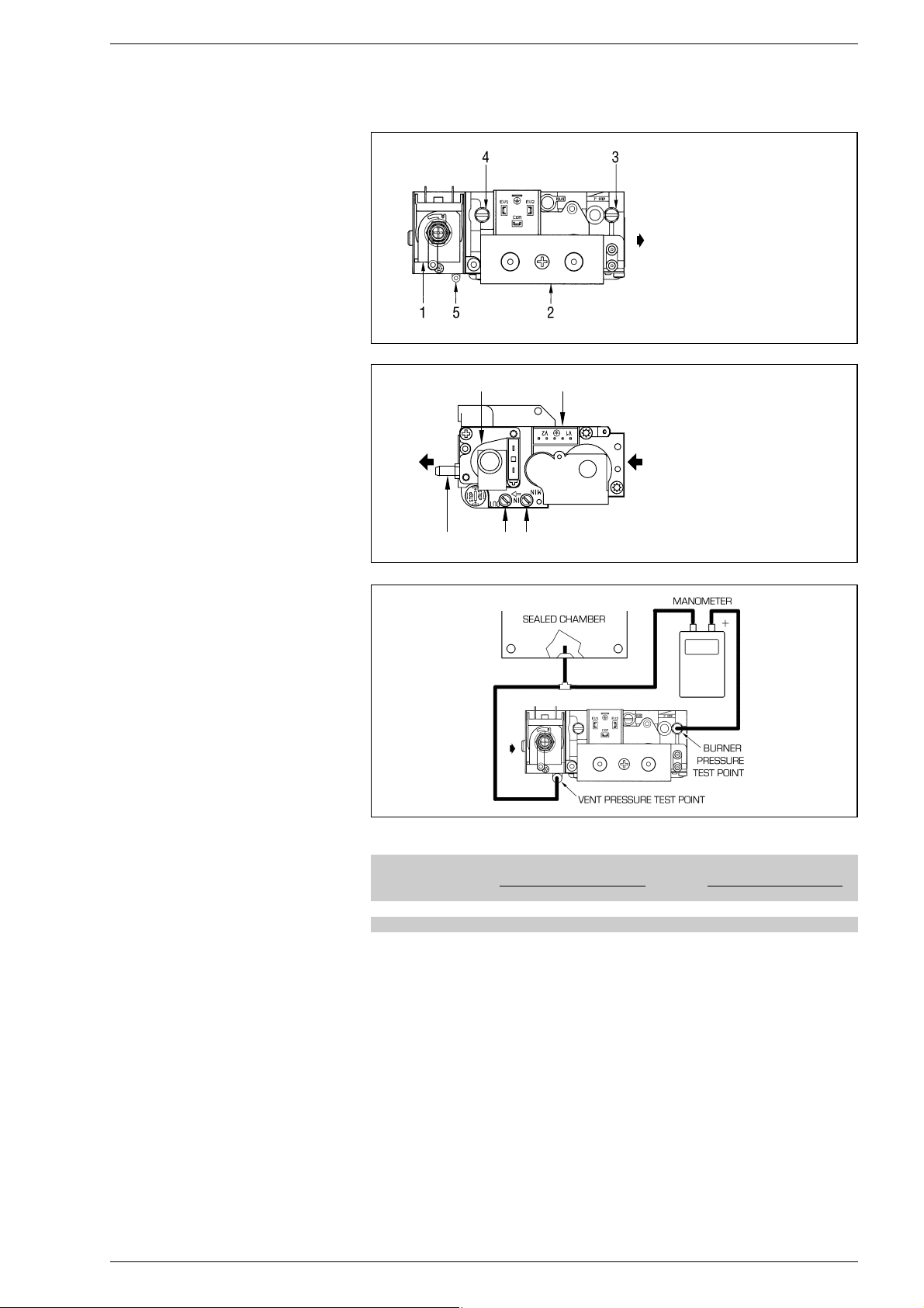
4.3 GAS VALVE
The “FORMAT” boilers, are equipped standard with the SIT 837 TANDEM gas valve (fig.
27) and with HONEYWELL VK 4105M gas
valve (fig. 27/a). The gas valve is set at two
pressure values: maximum and minimum.
According to the type of gas burnt, these correspond to the values given in Table 4. The
gas pressures at the maximum and minimum values, are factory set. Consequently
they must not be altered.
Only when you switch the appliance from one
type of gas supply (methane) to another
(butane or propane), it is permitted to alter
the operating pressure. It is essential that
this operation is carried out exclusively by
authorized technical staff. When the
working pressures have been adjusted,
reseal the regulators.
When the gas pressures are to be reset,
this must be done following a set order
first
setting the MAXIMUM and then the MINIMUM.
4.3.1 Maximum pressure adjustment
valve SIT (fig. 28)
To set the maximum pressure, proceed as
follows:
– Connect the pressure column or a pres-
sure gauge to the pressure inlet downstream of the gas valve. In the “30 BF”
versions, instead, connect the manome-
ter as shown in fig. 27/b.
– Remove the plastic cap (1).
– Set the knob of the D.H.W. potentiome-
ter to the maximum value.
– Ignite the boiler by operating the switch
and open the hot water tap.
–
Using a ø 10 spanner, turn the nut (3) to
arrive at the maximum pressure value
given in Table 4: to reduce the pressure,
turn the nut counterclockwise; to increase the pressure, turn it clockwise.
–
Operate the main switch a number of
times, keeping the hot water tap open all
the time, and check that the pressure corresponds to the values given in
Table 4
.
4.3.2 Minimum pressure adjustment
valve SIT (fig. 28)
After having adjusted the maximum pressure, calibrate the minimum pressure as follows:
– Disconnect the electric power to the
modulator.
88
KEY
1 Modulator
2 EV1 - EV2 coils
3 Pressure inlet upstream
4 Pressure inlet downstream
5 VENT pressure test point
Fig. 27/a
TABLE 4
Burner max. Modulator Burner min. Modulator
Type of gas pressure current pressure current
mbar mA mbar mA
Methane - G20 9 - 11 130 2 0
Butane - G30 27 - 28 165 5 0
Propane - G31 35 165 5 - 7 0
Fig. 27/b
4 USE AND MAINTENANCE
Fig. 27
KEY
1 Modulator
2 EV1 - EV2 coils
3 Pressure inlet downstream
4 Pressure inlet upstream
5 VENT pressure test point
1
4 35
2
Page 18
89
– With the domestic hot water potentio-
meter knob on maximum, the domestic
hot water tap open and the burner ignited, turn the screw (2) keeping locked
the nut (3) to achieve the minimum pressure value given in
Table 4
: to reduce the
pressure, turn the screw counterclockwise; to increase the pressure, turn
it clockwise.
–
Operate the main switch a number of
times, keeping the D.H.W. tap open all the
time, and check that the pressure corresponds to the values given in Table 4.
– Restore electric power to the modulator.
– Replace the plastic cap (1) in position.
4.3.3 Maximum pressure adjustment
valve HONEYWELL (fig. 28/a)
To set the maximum pressure, proceed as
follows :
–
Connect the pressure column to the pressure inlet downstream of the gas valve.
– For the “BF” models connect the pressu-
re column as shown in fig. 27/b.
– Remove the plastic cap on the modula-
tor (1).
– Set the knob of the D.H.W. potentiome-
ter to the maximum value.
– Ignite the boiler and open the D.H.W. cock.
– Using a ø 9 spanner, turn the nut (3) to
achieve the maximum pressure value
given in
Table 4
: to reduce the pressure,
turn the nut counterclockwise; to increase the pressure, turn it clockwise.
–
Operate the main switch a number of
times, keeping the D.H.W. cock open all the
time, and check that the pressure corresponds to the values given in Table 4.
4.3.4 Minimum pressure adjustment
valve HONEYWELL (fig. 28/a)
After adjusting maximum pressure, proceed to calibrate minimum pressure:
–
Disconnect the electric power supply
from the modulator.
–
With the hot water potentiometer
knob set to the maximum, the hot
water tap turned on and the burner lit,
hold nut (3) locked in place and simulta-
neously turn nut (2) using a fixed ø 7
wrench to identify the minimum pressure value shown in Table 4: turn the
nut anti-clockwise to reduce pressure
or clockwise to increase it.
– Turn the boiler on and off repeatedly
while keeping the hot water tap turned
on, checking that pressure corresponds
to the values shown in Table 4.
– Connect up the power supply to the
modulator again.
– Replace the plastic cap (1).
4.4 ADJUSTMENT OF HEAT
OUTPUT FOR HEATING
To adjust boiler heat output for heating purposes, i.e., modifying the setting made at the
factory which is approximately 16 kW, use a
screwdriver to adjust the heating heat output
trimmer (1 fig. 21). To increase working pressure, turn the trimmer clockwise; to reduce
pressure, turn the trimmer counterclockwise.
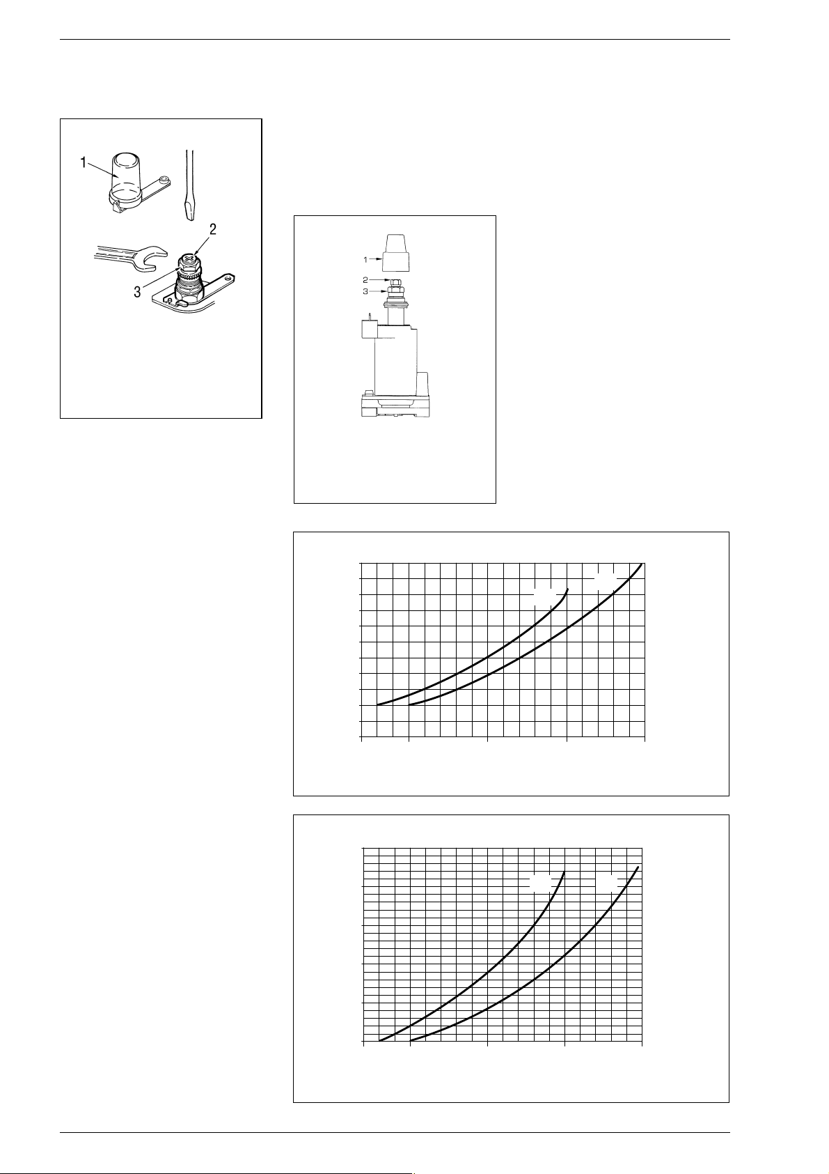
To facilitate the operations of adjusting heat
output, see the pressure/heat output diagrams for natural gas (methane) and butane
or propane gas (figg. 29 - 29/a - 29/b).
KEY
1 Plastic cap
2 Minimum pressure adjusting screw
3 Maximum pressure adjusting nut
Fig. 28
Fig. 28/a
KEY
1 Plastic cap
2 Minimum pressure adjusting nut
3 Maximum pressure adjusting nut
11
10
9
8
7
6
5
4
3
2
1
8,1 (7.000) 11,6 (10.000) 17,4 (15.000) 23,2 (20.000)
POTENZA TERMICA kW (kcal/h)
PRESSIONE UGELLO mbar
29,0 (25.000)
25
30
Fig. 29
Pressure/heat output diagram for natural gas (methane)
25
20
15
10
8,1 (7.000) 11,6 (10.000) 17,4 (15.000) 23,2 (20.000)
POTENZA TERMICA kW (kcal/h)
PRESSIONE UGELLO mbar
30
5
29,0 (25.000)
25 30
Fig. 29/a
Pressure/heat output diagram for butane gas (G30)
HEAT OUTPUT kW (kcal/h)
NOZZLE PRESSURE mbar
HEAT OUTPUT kW (kcal/h)
NOZZLE PRESSURE mbar
Page 19

4.5 GAS CONVERSION
A kit is supplied complete with the necessary
change-over materials for operation with
butane gas (G30) or propane gas (G31).
Operate in the following manner for changing
over from one gas to another (fig. 30):
– Close the gas cock.
– Slide out the burner unit.
– Replace the main nozzles supplied in a kit
(6), inserting the copper washer (4).
Use a ø 7 spanner to perform this operation.
– Remove the “GPL-MET” connector link on
the card and set it on “GPL”(4 fig. 21).
– To set the values of maximum and mini-
mum gas pressure, follow the instructions given in section 4.3, according to
the type of gas valve used.
When the working pressures have
been adjusted, reseal the regulators.
– The gas feed pressure must, under no
circumstances, exceed 50 mbar.
– After have ultimated the conversion of
the boiler, please stick onto the casing
panel the plate showing the relevant feeding gas which is included into the kit.
NOTE: After assembling all the gas connections, a test for gas tightness must be carried out using soapy water or special products. Do not use naked flames. The conversion to different gas must be carried out
exclusively by authorized technical personnel.
4.6 DISASSEMBLY OF
EXPANSION VESSEL
To disassemble the expansion vessel, proceed as follows (fig. 31):
– Make sure that the water has been emp-
tied out of the boiler.
– Unscrew the connection (1) and the lock-
nut (5).
– Remove the bracket and the expansion
vessel (4).
NOTE: Before refilling the system, using a
pressure gauge attached to the valve (3)
make sure that the expansion vessel is
preloaded at a pressure of 0.8 to 1 bar.
4.7 REMOVAL OF OUTER CASING
It is possible to completely disassemble the
shell for an easy maintenance of the boiler
following these simple instructions (fig. 32):
– Remove the two screws and bracket (6)
locking the front panel to the sides.
– Pull the front panel forwards so as to
release it from the slot-in pins located on
the sides.
– Unscrew the two screws fixing the instru-
ment panel to the sides.
– Unscrew the four screws fixing the sides
to the instrument panel support.
– Push the sides (3) and (4) upwards, sli-
ding them out of their slots.
90
Fig. 32
KEY
1 Self-tapping screw
2 Rear panel
3 L.H. side panel
4 R.H. side panel
5 Front panel
6 Fixing bracket
Fig. 31
KEY
1 Connection 3/4”
2 Expansion vessel
3 Preloaded valve
4 Fixin bracket
5 Locknut 1/2”
Fig. 30
KEY
1 Swivel connection
2 Locknut 1/2”
3 Burner manifold
4 Washer ø 6.1
5 Burners
6 Nozzle M6
7 Screw
25
20
15
10
8,1 (7.000) 11,6 (10.000) 17,4 (15.000) 23,2 (20.000)
POTENZA TERMICA kW (kcal/h)
PRESSIONE UGELLO mbar
30
35
5
29,0 (25.000)
25 30
Fig. 29/b
Pressure/heat output diagram for propane gas (G31)
HEAT OUTPUT kW (kcal/h)
NOZZLE PRESSURE mbar
WARNING: To ensure a perfect seal,
always use the washer (4) supplied in the
kit when replacing nozzles, even in burner units for which it is not specified.
Page 20
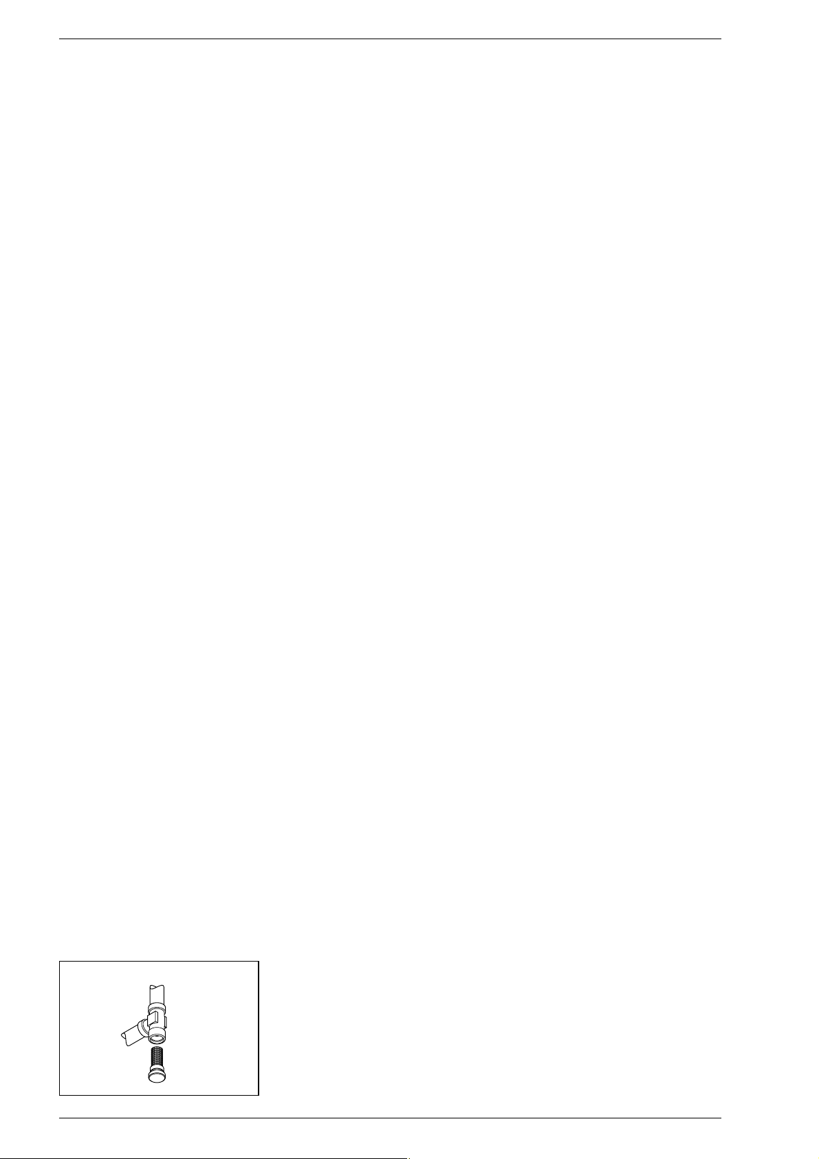
4.8 CLEANING AND
MAINTENANCE
At the end of each heating season, it is
essential to have the boiler thoroughly
checked and cleaned out.
Proceed as follows:
– Turn the main switch off to stop electric
power reaching the boiler and close the
gas feed cock.
– Remove the outer casing as described in
section 4.7.
– Remove the gas burner manifold unit
(fig. 30).
– To clean the burner, blow in a jet of air, so
as to remove any dust particles that may
have accumulated.
– Clean the heat exchanger, removing any
dust or residue from combustion.
– When cleaning the heat exchanger or
the burners, chemical products or steel
brushes MUST NOT BE USED.
–
Make sure that the tops of the burners
with the holes are free from encrustations.
– Reassemble the items removed from
the boiler, making sure to follow the correct sequence.
– Check the chimney to make sure that
the flue is clean.
– Check operation of the equipment and
the main burner.
– After assembly of all the gas connec-
tions, these must be tested for soundness, using soapy water or appropriate
products.
DO NOT USE NAKED FLAMES.
– Do not use calcium chloride to treat the
plastic component during generator
maintenance.
Preventive maintenance and checking of
efficient operation of equipment and
safety devices must be carried out exclusively by authorized technical personnel.
4.8.1 Cleaning the C.H.
water filter (fig. 33)
To clean the filter, close the delivery/return
on/off taps, turn off the power to the control panel, remove the casing and empty the
boiler using the drain provided (9 fig. 7) until
the hydrometer shows “zero”. Place a container for collection underneath the filter,
unscrew the cap and proceed to clean the
filter, removing impurities and limestone
deposits. Check the seal o-ring before reassembling the cap with the filter
4.9 FAULT FINDING
The burner does not ignite and the circulator is working.
– Check that the water pressure reads 1 -
1.2 bar.
– The flowmeter is faulty, replace it.
– The flow switch has been tripped becau-
se the heating circuit filter is obstructed
with impurities; it needs cleaning.
Main burner does not start either to draw
off D.H.W. or for heating.
– Check flowmeter; if necessary, replace it.
– The smoke stat has tripped; reset it.
– Check whether electric power is rea-
ching the gas valve actuator; check its
operation and, if necessary, replace it.
– Check operation of the smoke pressure
switch (“BF” vers.).
– The fan is operating but at low rpm, so
failing to activate the smoke pressure
switch (“BF” vers.); replace the fan.
– Replace the electronic card.
Boiler turns on, but after 10 seconds
“locks out”.
– Check that during electric wiring the
position of line and neutral have not been
inverted.
– The sensing electrode is faulty; replace it.
– The control box is faulty; replace it.
Gas valve fails to modulate in D.H.W. and
C.H. modes.
– The sensor is interrupted; replace it.
– The modulator has a break in winding;
replace it.
– Check that the current to the modulator
complies with the specifications
– The electronic card is faulty; replace it.
Main burner fails to start in D.H.W. production mode.
– Unscrew completely the screw of the
pressure switch valve (5 fig. 7)
– Check that the filter on the pressure
switch valve inlet is clean (3 fig. 7).
– Mains water charge pressure is too low;
install water-lift system.
– The microswitch of the pressure switch
valve is faulty; replace it.
D.H.W. is very hot but at low flow rate.
– Exchanger or D.H.W. outlet pipe obstruc-
ted by lime deposits; remove encrusta-
tions.
D.H.W. potentiometer and heating potentiometer fails to regulate properly.
– Check that the sensor in question is in
contact with the pipe; use silicone paste
to improve sensitivity.
– The sensor in question is faulty; replace.
Boiler is noisy or heat exchanger makes a
sizzling sound.
– Check whether circulation pump P is
obstructed; if necessary clear it out.
– Unclog impeller of circulation pump, clea-
ring away any impurities or sediments.
– Circulation pump is burnt out or has a
lower rpm than required; replace it.
– Check boiler output is adequate for
actual needs of heating system.
Boiler safety valve keeps tripping.
– Check charge cock is closed. If it doesn’t
close properly, replace it.
–
Check system cold charge pressure is not
too high; keep to recommended values.
– Check whether safety valve is out of cali-
bration; if necessary, replace it.
– Check whether the vessel is sufficiently
capacious to contain the water for the
system.
– Check preloading pressure of expansion
vessel.
– Replace expansion vessel if faulty.
Radiators fail to heat up in winter.
– The rotary switch is on “Summer”; swit-
ch to “Winter”.
– The room stat is set too low or needs
replacing because faulty.
– The electrical connections of the room
stat are wrong.
– The microswitch of divertor valve is
faulty; replace it.
Main burner burns badly: flames too high,
deep yellow.
– Check that pressure of burner gas is
regular.
– Check burners are clean.
– Check coaxial assembly has been instal-
led correctly (“BF” vers.).
Smell of unburnt gases.
– Check boiler is properly clean.
– Check draught is sufficient.
– Check gas consumption is not too high.
Boiler operates but does not increase
temperature.
– Check gas consumption is not lower
than it should be.
– Check boiler is clean.
– Check boiler is sized in proportion to
system.
In the “FORMAT” boilers, upon demand for
D.H.W. or heating, fan fails to turn at max
speed.
– Make sure that the smoke pressure
switch is working and that the relative
contact is in the rest position.
– Check whether connection tubes of
smoke pressure switch are obstructed
and, if necessary, clean away impurities
or condensate.
– The smoke pressure switch needs repla-
cing.
– Replace electronic board.
91
Fig. 33
Page 21
92
USER INSTRUCTIONS
WARNINGS
– In case of fault and/or incorrect equipment operation, deactivate it, without making any repairs or taking any direct
action. Contact the nearest Authorised Technical Service Centre.
– The installation of the boiler and any servicing or maintenance job must be carried out by qualified personnel. Under
no circumstances, the devices sealed by the manufacturer can be tampered with.
– It is absolutely prohibited to block the intake grilles and the aeration opening of the room where the equipment is
installed.
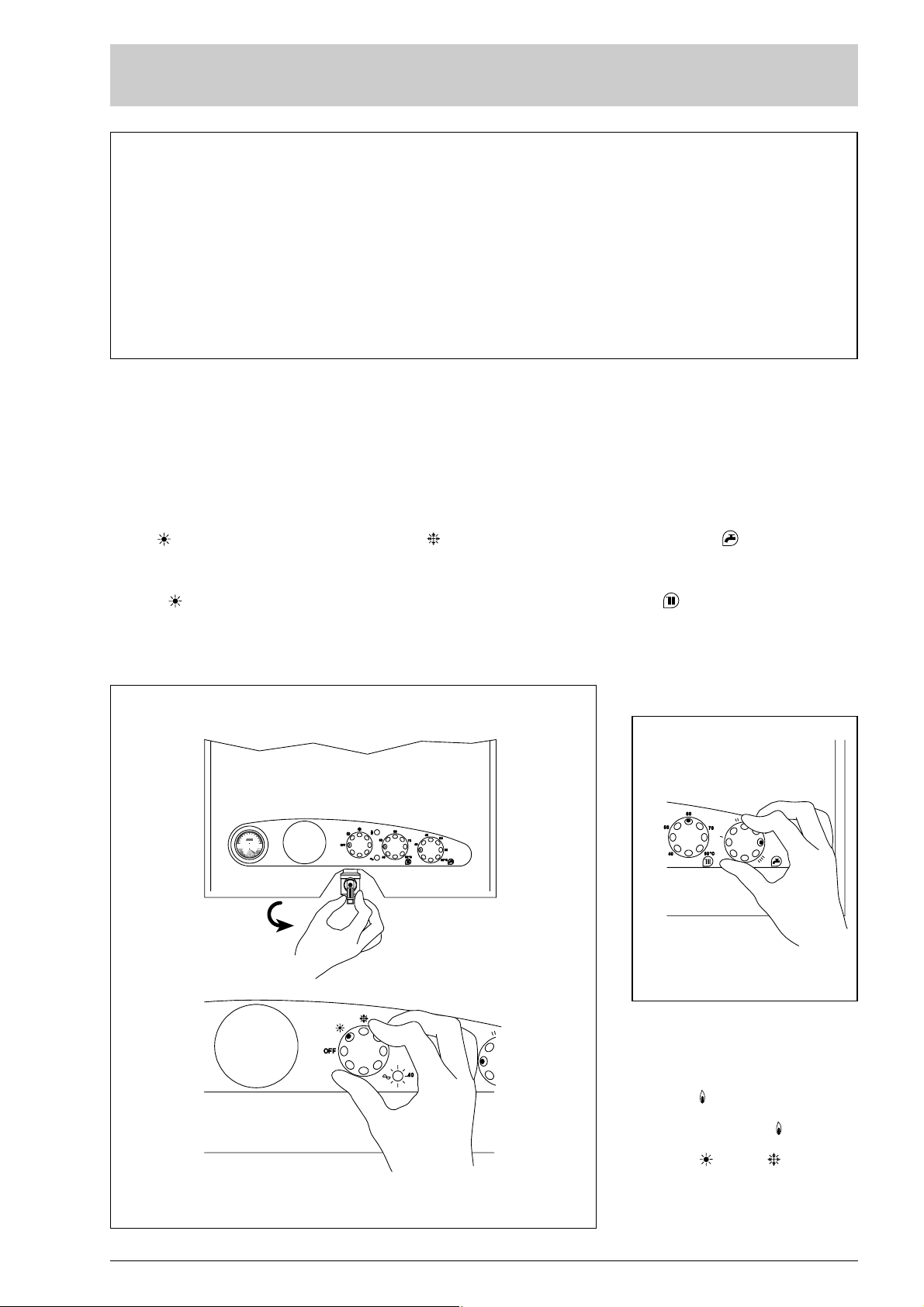
LIGHTING AND OPERATION
BOILER IGNITION
Open the gas valve and light the appliance
by turning the rotary switch to summer
position
(fig. 1).
The green led indicates that electricity is
being supplied to the appliance.
– With the rotary switch in the summer
position , the boiler will start-up upon
demand for domestic hot water, and run
at full power to reach the selected temperature.
The gas feeding pressure will then automatically vary to ensure that the required temperature is kept constant.
– With the rotary switch in the winter
position , once the boiler has reached
the value set on the heating potentiometer, it will star t to modulate in automatically in order to supply the required
power output to the system.
The operation of the boiler will be stopped through the intervention of the thermostat or timer.
TEMPERATURES ADJUSTMENT
– The D.H.W. temperature can be adju-
sted by turning the knob of the D.H.W.
potentiometer which has a range of
between 40 to 60°C (fig. 2).
– The C.H. temperature can be adjusted by
turning the knob of the C.H. potentiometer which has a range of between 40
to 80°C.
To ensure optimal boiler efficiency at all
times, we recommend not to drop below
a minimum working temperature of
50°C (fig. 2).
LOCK OUT RESET OF
THE CONTROL BOX
If the burner does not ignite, the red lock
out indicator will light up (fig. 3).
In order to re-attempt boiler ignition, place
the rotary switch to the position and
release it immediately, then turn it back to
the summer or winter .
Should the appliance again “lock out”,
please approach the authorized technical
staff.
Fig. 1
Fig. 2
OPEN
306090
0
°C
120
bar
034
1
APRE
Page 22
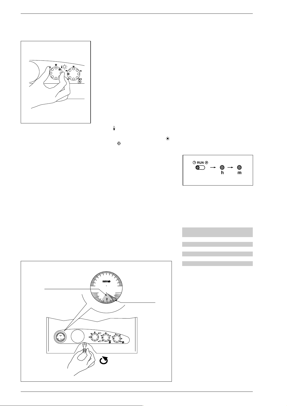
TURNING OFF BOILER
To turn off the boiler set the switch to “OFF”
and close the gas-feeding pipe tap if the boiler remains inoperative for a long period
(fig. 1).
SYSTEM FILLING (
fig. 4)
Check periodically that the thermomanometer shows a reading of between 1 - 1.2 bar
(1), with the system cold.
If the pressure drops below the blue scale
(1), the boiler will not operate.
To re-set the pressure, rotate the charging valve to the anticlockwise direction
until the thermomanometer reading reenters the blue scale (1).
Once this operation is completed, make
sure the tap is closed.
In case the pressure goes above the limit,
empty the exceeding pressure by opening
the pressure relief valve on any radiator.
The blue part of the scale (2) indicates the
working pressure range with the heating in
operation. Should the pressure exceed the
values of the blue scale (2), causing the
safety valve intervention, call the authorized
technical staff.
"25 OF - 30 OF" SMOKE
SAFETY DEVICE
This is a safety device against possible
smoke emission into the ambience.
The safety device switches off the gas valve
when the return of the smokes into the
ambience is continuous and then dangerous. The intervention of this device locks
out the appliance because the burner is not
ignited. In this case, turn the rotary switch
to the
position
(fig. 3)
nd release it imme-
diately, then turn it back to the summer
or winter .
Should the boiler “lock out” again, you
must call the authorized technical staff.
GAS CONVERSION
Should it be necessary to convert the
appliance to a dif ferent gas from the one
for which the boiler has been equipped,
approach the technical staff.
CLEANING AND MAINTENANCE
At the end of each heating season, it is
essential to have the boiler thoroughly
checked and cleaned out.
Preventive maintenance and checking of
the efficient operation of the equipment
and safety devices must be carried out
exclusively by the authorized technical
staff.
The boiler is supplied with an electric
cable. Should this require replacement,
contact exclusively with the authorized
technical staff.
TIME PROGRAMMER (optional)
With the selector in the “AUTO” position,
the boiler operation is regulated according
to the temperatures set for the programmed time periods.
During star t-up, the second selector must
be in the “RUN” position. Programming:
– Setting the time (fig. 5)
Move the selector to “”. To change the
hour on the display, press the “h” button,
to change the minutes, press the “m”
button.
To set the day, press button “1...7” until
the arrow points to the correct day (1 =
Monday ....... 7 = Sunday).
– Setting the programme (fig. 6)
The programmer has 8 start-up programmes and 8 shutdown options.
To make programming easier, 3 star t-up
and 3 shutdown programmes have
already been set up for each day of the
week, as follows:
NOTE:Programmes from 7 to 16 are not
pre-set.
To select programmes other than those
pre-set, move the selector to the “P”
position: “0:00 1” will appear on the
display: the first three figures indicate
the hour and minutes, the fourth figure is
the number of the programme.
Programmes with odd numbers are switch-on times (daytime temperature) and
are indicated on the display by a light bulb
symbol. Programmes with even numbers
indicate the temperature reduction
(night).
Use button “1...7” to select the day of the
week (from 1 to 7), or the period (1 ÷ 5,
6 - 7; 1 ÷ 6; or every day if the programme has to be repeated every day of the
week). Set the hour and minutes using
buttons “h” and “m”.
The operation in memorized by pressing
button “P”
93
Fig. 3
Fig. 4
Programa Hora de Hora de
encendido apagado
1 06.00 2 - 09.00
3 12.00 4 - 14.00
5 18.00 6 - 22.00
Fig. 5
BLUE SCALE (1)
BLUE SCALE (2)
OPEN
SCALA COLORE AZZURRO
60
30
90
120
0
°C
bar
0
4
1
3
60
30
90
0
120
°C
bar
0
4
1
3
SCALA COLORE BLU
APRE
Page 23
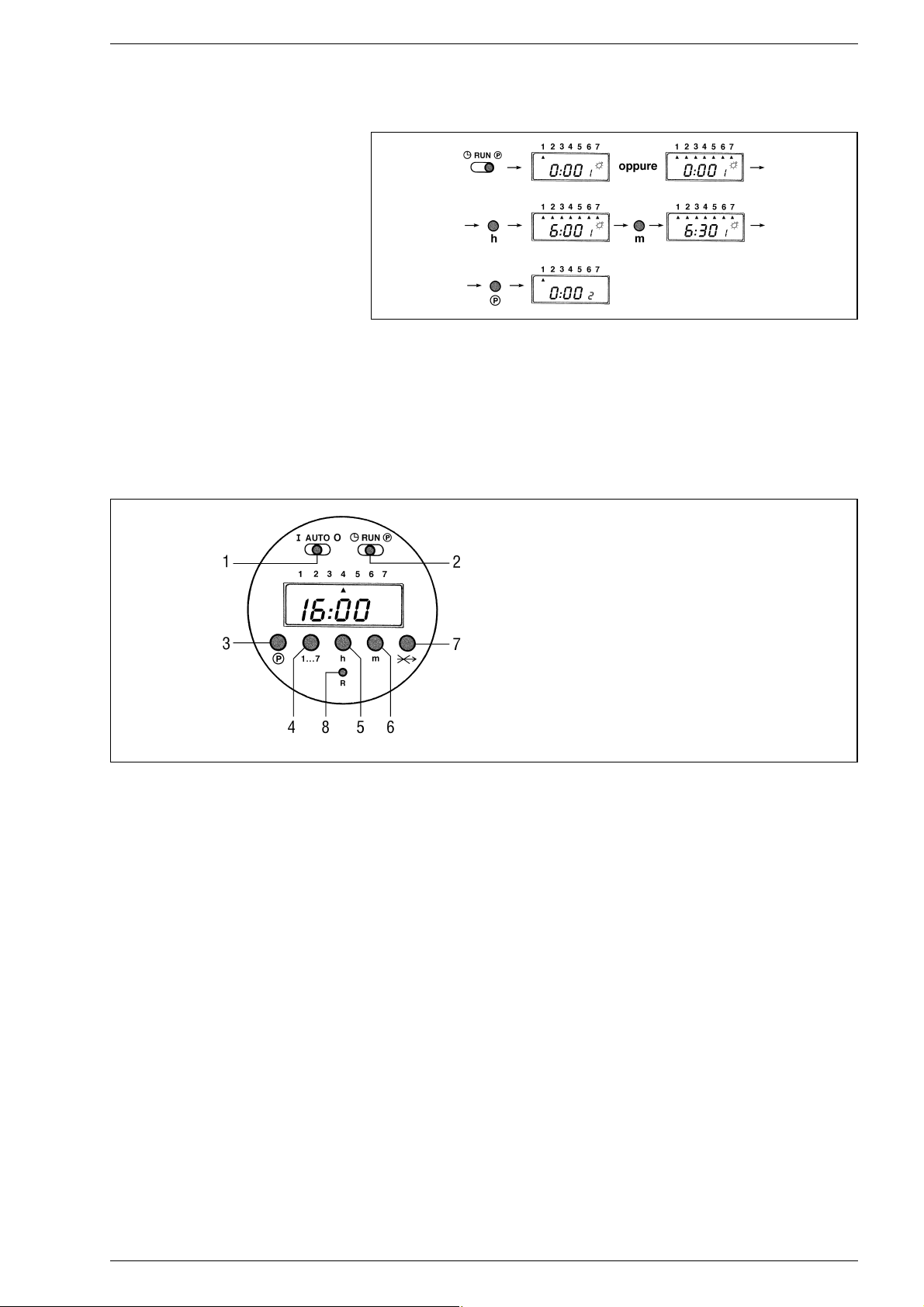
The display then changes to the further
programme. Repeat the same operations to set the successive programmes.
At the end of the programming. Move the
selector to the “RUN” position.
– Cancelling one or more
programmes (fig. 7)
The programmed switch-on time and
switch-off time must be cancelled for
each individual programme by moving
selector (2) to the “P” position.
Select the required programme with button (3), press button (4) to cancel the
settings for that day (the triangular day
indicator should disappear).
If a par t of the programme is cancelled,
when selector (2) is returned to the
“RUN” position, an error message will
appear on the clock display together with
an indication of the incorrect programme. To cancel all the programmes, move
the selector to the “P” position and press
buttons (3) and (5) simultaneously.
– Setting the “SKIP” function (fig 7)
The SKIP function defused the programmes when going out for the day, during
which no heating is required.
To start this function, press button (7);
the button is only active when selector (2)
is in the “RUN” position.
Once selected, the SKIP function becomes active at 0:00 of the following day
and lasts for 24 hours.
Once activated, it cannot be defused.
Consequently the normal programme
will only be resumed after 24 hours.
94
KEY
1 Manual/automatic operation selector
2 Programmer/timer setting selector
3 Programme button
4 Day button
5 Hour button
6 Minute button
7 SKIP function button
8 Reset button
Fig. 6
Fig. 7
 Loading...