

Page 1
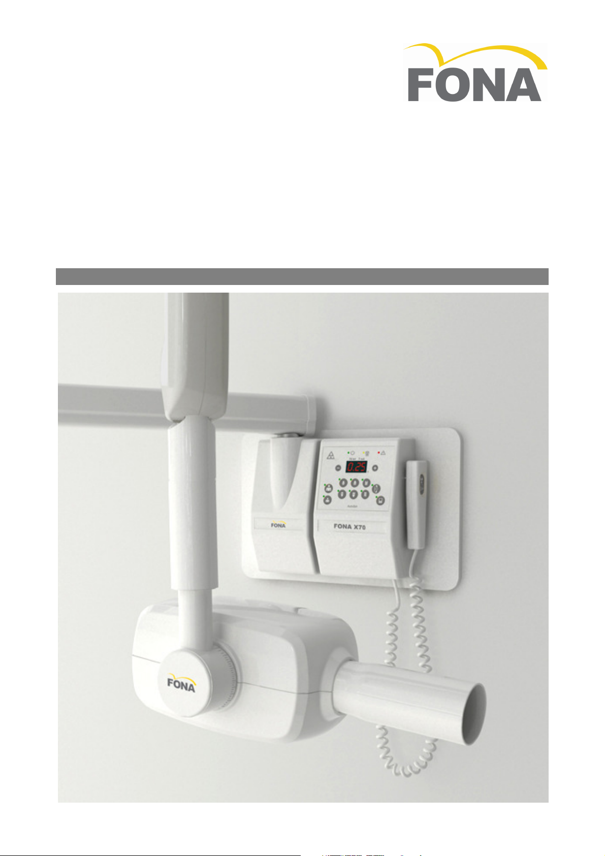
FONA X70
Operating Instructions
English
Page 2
Table of Contents
FONA X70 Operating Instructions
English Edition
Version 110720 July 2011
Code 69 500 70110
Manufactured by FONA S.r.l.
Via Idiomi 1/8-33 - 20090 Assago (MI) Italy
Distributed by FONA Dental s.r.o.
Stefanikova 7 SK-811 06 Bratislava, Slovakia www.fonadental.com
1. INTRODUCTION .......................................... 3
1.1 Congratulations ................................... 3
1.2 Purpose .............................................. 3
1.3 Equipment Classification ...................... 3
1.4 Obligations of the User ........................ 3
1.5 Warning ............................................. 3
1.6 Safety Recommendations .................... 3
2. TECHNICAL DATA ....................................... 4
2.1 System Supply .................................... 4
2.2 Tube Housing Assemblies .................... 4
2.3 Beam Limiting Device .......................... 4
2.4 AutoSet Timer ..................................... 4
2.5 Mechanical Suspension System ............ 4
2.6 Weights .............................................. 4
3. OPERATING INSTRUCTION.......................... 5
3.1 The Control Panel ............................... 5
3.2 Beam Limiting Device .......................... 5
3.3 Use of the AutoSet Timer .................... 6
3.4 Operation ........................................... 7
3.5 Operational Remarks ........................... 7
FONA X70 – Operating Instructions
3.6 Moving the mobile unit ........................ 7
3.7 The Timing Table ................................ 8
4. CARE AND MAINTENANCE ........................... 8
4.1 Cleaning ............................................. 8
4.2 Disinfecting ......................................... 8
4.3 Maintenance ....................................... 8
5. DISPOSING OF OBSOLETE EQUIPMENT ........ 8
6. ELECTROMAGNETIC COMPATIBILITY ........... 8
6.1 Electromagnetic Emissions ................... 8
6.2 Electromagnetic Immunity ................... 9
6.3 Non-Life Supporting Equipment ............ 9
6.4 Separation Distance for non-life
supporting equipment ...................................... 9
Appendix A Systems and Components ................ 10
Appendix B Icons .............................................. 11
Appendix C Exposure Table ................................ 12
Appendix D Alarm Conditions ............................. 13
Appendix E Identification Labels ......................... 14
Appendix F Cooling Curves ................................. 14
2/16 69 500 70110 110720
Page 3
FONA X70 – Operating Instructions
1. INTRODUCTION
1.1 Congratulations
Congratulations! You have purchased a state of the art equipment which will assist in your profession day
after day performing consistently for many years. The unit is manufactured under a Quality Control System
which grants full compliance to specifications.
1.2 Purpose
The FONA X70 X-ray equipment is design to fulfill the needs for intra-oral radiography in the general dental
practice. The systems can be configured for wall or mobile solutions.
The Operating Instructions and the Service and Installation Manuals supplied with the system are integral
part of the product. The original language of the Operating Instructions is English.
1.3 Equipment Classification
• IEC: FONA X70 is a Class I, type B equipment
• FDA: FONA X70 is a Class II medical device equipment
(21 CFR 872-1800).
1.4 Obligations of the User
It is the responsibility of the User:
• To follow the instructions and recommendations contained in this Operating Instructions.
• To maintain the equipment in compliance by following the manufacturer’s recommended maintenance
schedule. Failure of the user to properly maintain the equipment may relieve the Manufacturer, or his
Agent, from responsibility for any injury, damage, or non-compliance which may result.
• To report promptly to the Health Authority in charge and to the Manufacturer or to its Agent any accident involving this medical device or any alteration in features and/or performances which could cause
death, injuries or health hazard to patient and/or operator.
Important information to be gathered and to be included in the report to the Manufacturer are the type
and serial numbers of the involved items which can be retrieved from the technical labels.
1.5 Warning
Use the system only after proper assembly and installation as per manufacturer’s instructions.
X-ray equipment produce ionizing radiation that may be harmful if not properly controlled. It is recommend-
ed that the equipment be operated by trained personnel only, in accordance with the existing laws.
Even if compliant to specifications of electromagnetic compatibility, it is recommended not to use the equip-
ment in presence of external electromagnetic fields, such as those generated by cellular phones, which
might interfere with the electronic circuits of the system.
1.6 Safety Recommendations
• Electrical.
Trained and qualified service technicians only are authorized to remove covers and have access to
power circuits.
Power supply lines must comply with safety legislation and have ground terminals for protective
earth connection.
Switch the equipment OFF and disconnect it from line voltage supply (with the room switch) before
cleaning or disinfecting the unit.
• Mechanical.
Check regularly (at least once a year) the status of supports and arms of the suspension system, in
case having necessary maintenance performed by a service technician.
• Explosion.
The equipment cannot be used in presence of flammable gases or vapors.
• Radiation.
Use the system only with round or rectangular collimator (BLD, beam limiting device) mounted.
The statutory radiation protection equipment must be used.
Patient safety during operation has to be ensured by the operator.
Make sure that the equipment is not left unattended.
• Environmental.
The equipment contains components which must be disposed-of following existing law.
110720 69 500 70110 3/16
Page 4
2. TECHNICAL DATA
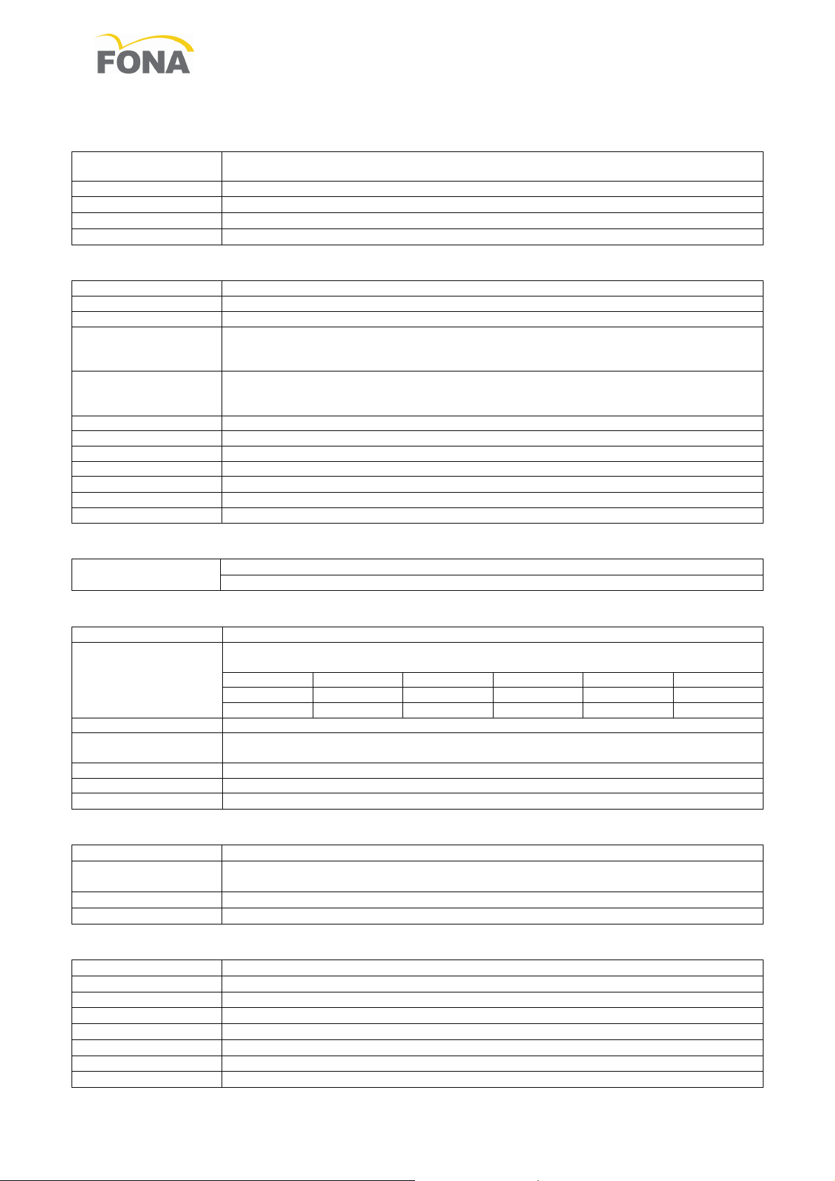
Line Voltage
115 V (
from 9
9 V to 132
V in sub
-
ranges depending on
THA mounted)
230 V
(from 198 V to 264
V in sub
-
ranges depending on THA mounted
)
Line Voltage Range
108 -
132 V for
type
93 202 01300
,
207 -
253 V for
type
93 202 01700
Line
Fuse
Slow Blow:
6.3 A at 115 V,
4 A at 230 V,
second fuse for two phases or cord
Line Frequency
50/60 Hz
± 1 Hz
Line resistance
≤ 0.4 Ohm at 115 V,
≤
0.8 Ohm
at 230 V
Nominal
Line Voltage
120 V for type 93 2
02
01300
,
230 V for type 93 2
02
01700
Nominal Line Current
6 A at 120 V for type 93 2
02 01300
,
4 A at 230 V for type 93 202
01700
Line Voltage Range
108 -
132 V for 93 202 01300,
207 –
253 V for 93 202 01700
Anode Voltage (peak
70 kVp ± 8% at nominal line voltage
74 kVp ± 8% at nominal line voltage+ 10%
Anode Current
7.0 mA ± 15% at nominal line voltage
8.3 mA ± 15% at nominal line voltage + 10%
Nominal Power
0.4 kW at
70 kVp, 7 mA, 0.1
s
X-ray Insert
3 electrodes, grid control action models: OCX/70
-
G, RF
8
G070
Anode
Tungsten
, angle 19° to the tube axis
Focal S
pot 0.8 (EN 60336:1995
-
04)
Inherent Filtration
> 2.5 mm Al
(EN 60522: 1999)
Duty Cycle
1/30
Radiation Lea
k
age < 0.1 mGy/h a 1 m (< 11.5 mR/h a 1 m)
Beam Limiting
Focus skin distance 21 cm (8.27”)
Circular
radiation field
6 cm (2.35”) diameter /Rectangular 3.2x4.2 cm (1.26”x1.65”)
Supply Voltage
110-120
for type 93 3
0
0 60200
,
220-240
for type 93 3
0
0 60100
Exposure factor
Exposure time in s, 18 steps from 0.06 s to 3.2 s (R10 scale)
. Time in seconds is
conv
erted to number of mains pulses (20 ms at 50 Hz, 16.6 ms at 60 Hz).
0.06 0.12 0.25 0.50 1.00 2.00
0.08 0.16 0.32 0.64 1.25 2.50
0.10 0.20 0.40 0.80 1.60 3.20
Precision
± 0.02 s or 5% (whichever the greater)
Exposure factor
s Automatic setting throug
h tooth type selection and patient
build
, for use with trad
i-
tional film or digital sensor, or manual setting with plus and minus keys.
Irradiation signal
Yellow light on hand
-
switch and on control panel plus acoustic buzzer
Hand
-
switch
Hand
-
switch with 3
m coiled cord, with remote mounting
optional kit
Overall size
Width:
15 cm /6”,
Height:
24 cm /9”½,
Depth:
9 cm /3”½
Wall Adaptor
12 cm /4.7” width, 24 cm /9.4” height, 9 cm /3.5” depth
Short (S): 30 cm /11.8”,
Medium (M): 60 cm /23.6”,
Long (L): 80 cm /31.5”, Extra Long (XL) 100 cm /39
.4”
Useful Reach
Arm S: 138 cm /54.3”, M: 168 cm /66.1”, L: 188 cm /74”, XL: 208 cm /
81.9”
Mobile Stand
Size 78 x 92 cm (30” ¾ x 36” ¼), Height: 186 cm /73” ¼” with scissor arm
Timer
1.7 kg / 3.7 lb
X-ray Head
6.6 kg / 14.5 lb
Circular BLD
0.1 kg / 0.22 lb
Rectangular BLD
0.2 kg / 0.44 lb
Scissor Arm
11.7 kg / 25.8 lb
Support Arm
Arm S: 2.8 kg /6.2 lb , M: 4.0 kg /8.8 lb, L: 4.8 kg /10.6 lb, XL: 5.4 kg /
11,9 lb
Wall Adaptor
1.3 kg / 2.9 lb
Mobile Stand
29.4 kg / 64.8 lb
2.1 System Supply
2.2 Tube Housing Assemblies
FONA X70 – Operating Instructions
tube potential)
(tube current)
66 kVp ± 8% at nominal line voltage – 10%
5.3 mA ± 15% at nominal line voltage – 10%
2.3 Beam Limiting Device
Device
2.4 AutoSet Timer
2.5 Mechanical Suspension System
Arm Length
2.6 Weights
4/16 69 500 70110 110720
Page 5
FONA X70 – Operating Instructions
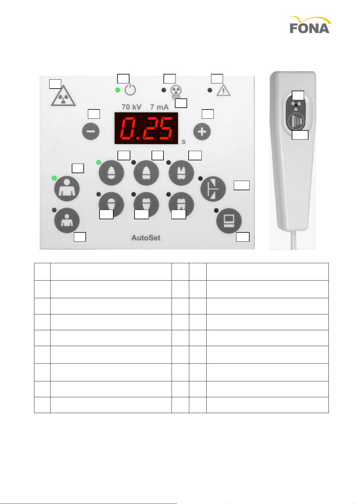
Device for emission of ionizing rad
i-
Indication of system turned ON and
Manual decrease of controlled
Manual increase of controlled
1
2 3 4
5
6 7
8
9
10 11 12
13 14 15
16
17
18
1
3. OPERATING INSTRUCTION
3.1 The Control Panel
1
ation on request
2
ready
3 Irradiation
4 Alarm
5 Exposure time in s
6
technique factor
7
technique factor
8 Patient build adult /large
9 Patient build child /small
10 Maxillary incisor
Maxillary canine or premolar
11
Maxillary molar
12
13 Mandibular incisor
Mandibular canine or premolar
14
Mandibular molar
15
16 Bite-wing premolar
17 Digital detector in use
18 Radiation exposure pushbutton
3.2 Beam Limiting Device
Systems are supplied with Beam Limiting Device (BLD) having Source Skin Distance (SSD) of 21 cm (8.27”),
circular radiation field of 6 cm (2.35”) diameter or rectangular 5.3 cm (2.1”) diagonal.
The devices are suitable for either bisecting or paralleling radiographic techniques, once conveniently angled.
The user is recommended to bring the rim of the collimator in touch with the film holder or with the face of
the patient to reduce possible blurring due to some movement during irradiation.
110720 69 500 70110 5/16
Page 6
FONA X70 – Operating Instructions
FILM SPEED INDEX
0.32
0.40
0.50
0.64
0.80
1.00
1.25
1.60
2.00
E type
D type
D type: Kodak Ultraspeed, Agfa Dentus M2
- E type: Kodak Ektaspeed Plu
s
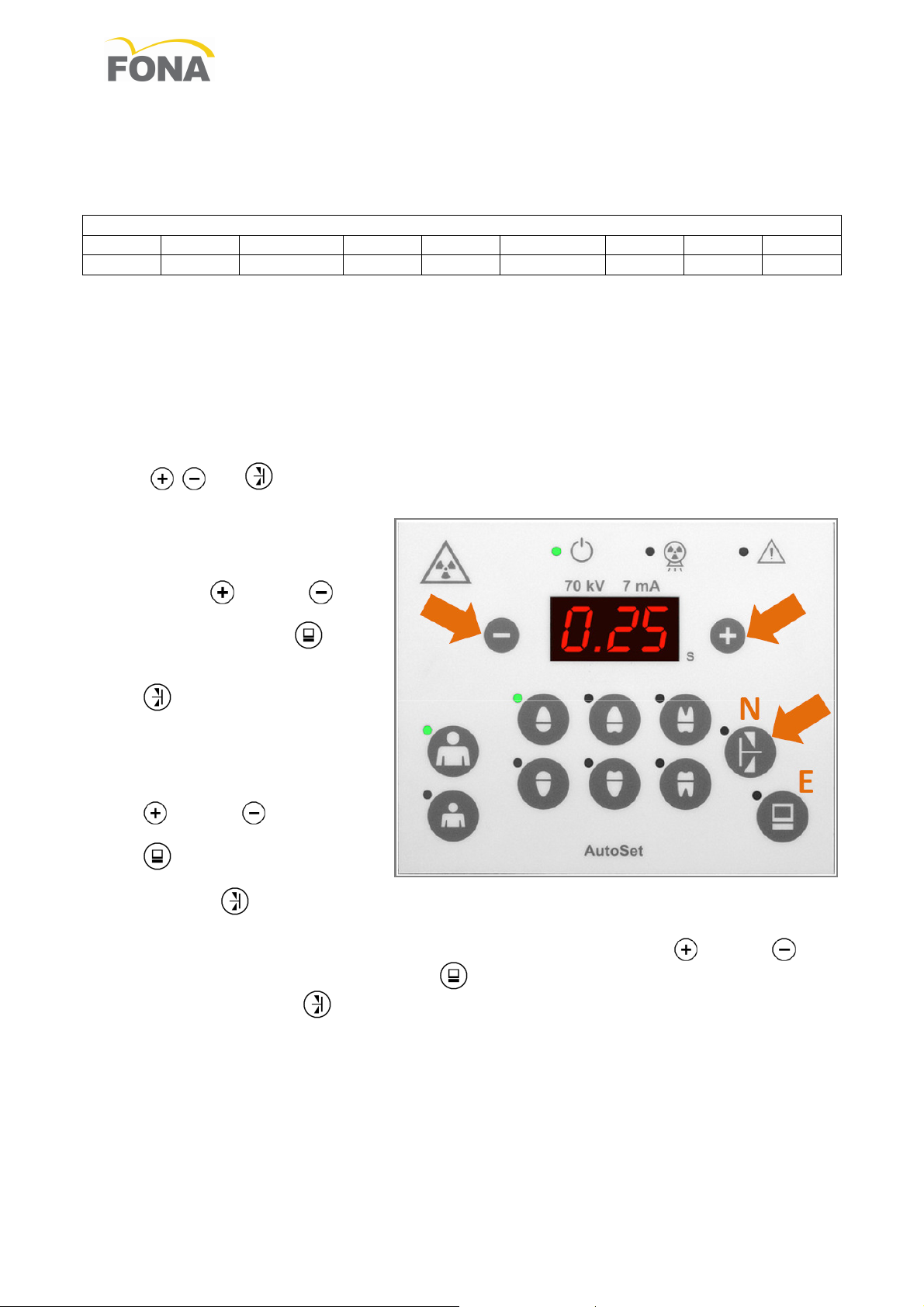
3.3 Use of the AutoSet Timer
Before using the timer make sure that the proper film speed indication and length of the beam limiting device have been properly set into the memory of the timer.
The timer offers the possibility to correct the exposure time to control radiation dose changes due to sudden
and strong fluctuations of the line voltage supply for a consistent film blackening. This functionality can be
enabled or disabled at time of installation with a dedicated switch (see the Service and Installation Manual).
When this functionality is enabled, the user is given the possibility to display the actual exposure time after
compensation instead of the one requested.
To set the desired working parameters follow the instructions below.
• SET-UP MENU.
Enter the set-up menu by switching on the unit while pressing at the same time, and for 2 s, the three
keys , , and .
The film speed selection mode is entered.
FILM SPEED. The number on the
display represents the index of
the speed of the film currently selected (see table above). Press
the PLUS or MINUS key to
change the value.
Press the COMPUTER key to
exit (E) input mode (back to normal operation) or the BITEWING
key to pass to next (N) selec-
tion.
BEAM LIMITING DEVICE. The
number on the display either “20”
or “30” represents the length of
the BLD in cm. Press the PLUS
or MINUS key to change
the value. Press the COMPUTER
key to exit (E) input mode
(back to normal operation) or the
BITEWING key for next (N) selection.
ACTUAL EXPOSURE TIME. The message on the display, either “on” or “OFF”, tells whether the ac-
tual corrected time or just the selected one will be displayed. Press the PLUS or MINUS keys
to change the value. Press the COMPUTER key to exit (E) input mode (back to normal opera-
tion) or the BITEWING key (E) to go back to first selection.
6/16 69 500 70110 110720
Page 7
FONA X70 – Operating Instructions
LINE
-
SWITCH ON/OFF
BELOW THE UNIT
EXPOSURE
PUSHBU
T
TON
YELLOW
LIGHT
Range of Selectable Times in s for the Au
toSet Timer
0.06 0.12 0.25 0.50 1.00 2.00
0.08 0.16 0.32 0.64 1.25 2.50
0.10 0.20 0.40 0.80 1.60 3.20
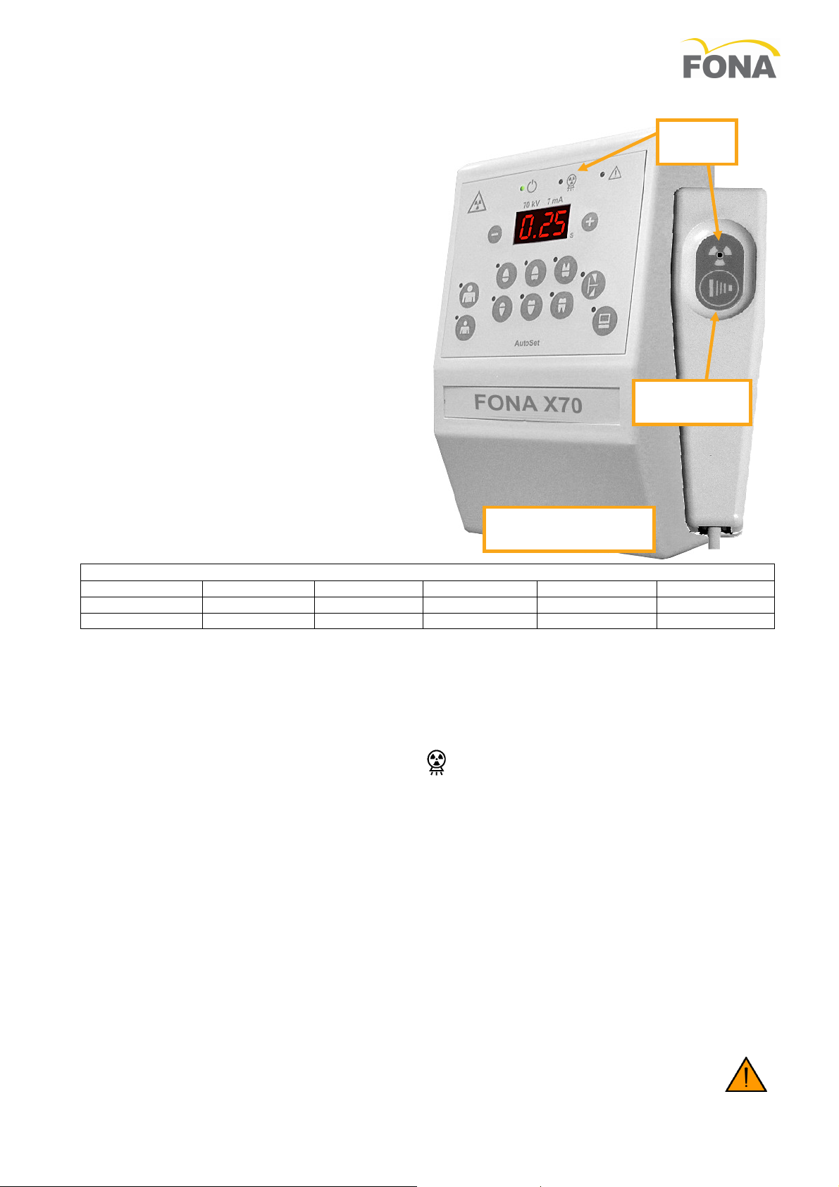
3.4 Operation
Turn on the line voltage supply with the switch below the timer.
1. Have the patient remove any provisional object
in the mouth which may affect image quality.
Position the image receptor where needed and
orientate the tube-head accordingly.
Operate with the rim of the collimator in touch
with the film holder or with the face of the patient
2. Select the desired exposure time with keys for
patient build, type of tooth and type of receptor
(press computer if required), or set the value
manually changing it with PLUS or MINUS keys.
3. Take the exposure hand-switch and move to a
convenient position of at least 2 m far from the
patient.
4. Press the exposure pushbutton. The exposure
yellow light and the buzzer indicate X-ray emission. Keep the exposure pushbutton pressed until the yellow light and the buzzer are switched
OFF to indicate the end of the exposure.
5. Hook back the exposure hand-switch and
process the image receptor exposed.
6. WARNING: If the exposure pushbutton is released before the end of the requested time, the
radiation emission is terminated and an alarm is
generated.
3.5 Operational Remarks
• The given range of selectable times is of 18 values from 60 ms to 3.2 s. Each step changes the radiation
energy of a minimum level of blackening (density). Every 3 steps upward the energy is doubled, every 3
steps downward the energy is halved.
• When the correction of dose variation due to line voltage fluctuations is activated, the corrected exposure time is 1) reduced if the line voltage is over the nominal level or 2) increased if it is below.
• During the exposure the yellow lights of X-ray ON on the control panel and on the hand-switch are
turned ON and the internal buzzer sounds to indicate radiation emission.
• An independent back-up device (back-up timer) is provided as additional safety feature to cut-off radiation in case of failure of the main timer.
• Alarm conditions are signaled by the red light and by a display message on the control panel.
• The timer implements the dead-man functionality with which radiation emission is stopped if the opera-
tor terminates the exposure by releasing the push-button before the requested exposure time has
elapsed. An alarm message is generated.
• The timer offers the possibility to correct the exposure time to control radiation dose changes due to
sudden and strong fluctuations of the line voltage supply for a consistent film blackening. This functionality can be enabled or disabled at time of installation with an internal switch.
• After each exposure the timer takes into account the cool-down period and prevents an immediate exposure which would exceed the energy allowed by the duty cycle, with a minimum waiting time of 3 s.
• During waiting time for cool-down the system is inhibited, and the digits on the display keep flashing,
until the energy of the requested exposure fits the heat capacity of the tube head. Once the waiting time
has expired, the display quit flashing and the system becomes ready.
3.6 Moving the mobile unit
The folding arm has to be closed in parking position every time the mobile unit is relocated.
110720 69 500 70110 7/16
Page 8
FONA X70 – Operating Instructions
Pulses 50
Hz
Pulses 60
Hz
Pulses @50
Hz
Pulses @60
Hz
0,06 0.42 3 4
0,50 3.50 25 30
0,08 0.56 4 5
0,64 4.40 32 38
0,10 0.70 5 6
0,80 5.60 40 48
0,12 0.88 6 7
1,00 7.00 50 60
0,16 1.12 8 10
1,25 8.75 62 75
0,20 1.40 10 12
1,60 11.2 80 96
0,25 1.75 12 15
2,00 14.0 100 120
0,32 2.24 16 19
2,50 17.5 125 150
0,40 2.80 20 24
3,20 22.4 160 192
Emission Test
Compliance
Electromagnetic environment
This
FONA X70
uses RF energy only for its internal function.
inte
rference in nearby ele
c
tronic equipment.
Class B
Harmonic e
missions
EN 61000
-3-2
Complies
Class A
Voltage fluctu
a
tions/
EN 61000
-3-3
3.7 The Timing Table
Here below the timing indications in s and in line pulses at 50 and 60 Hz as well as mAs at 7 mA.
s mAs
s mAs
4. CARE AND MAINTENANCE
4.1 Cleaning
Always disconnect the line voltage supply before cleaning the unit. Use a mild soap to remove finger or other dirty marks paying attention not to have liquids enter into the equipment. Plastic covers can be wiped with a soft cloth and light detergent. Avoid the use solvents or corrosive detergents
4.2 Disinfecting
Parts in touch with the patient must be cleaned with a detergent (such as 2% solution of ammonia) and
then disinfected making sure not to use solvents or corrosive disinfectants. which can cause cracks on the
plastic covers.
4.3 Maintenance
Maintenance for the FONA X70 systems to be done regularly by a service technician at least once
every 24 months, in addition to regular checks performed by the operator every year.
5. DISPOSING OF OBSOLETE EQUIPMENT
A radiological system is made of different materials which include many kinds of metals (iron,
aluminum, lead, copper and others), plastic materials, electronic components and dielectric oil in
the tank of the X-ray tube.
The "crossed-out wheeled bin" symbol on the product indicates that the product at the end of its
useful life must not be disposed of as unsorted municipal waste but has to be collected separately and delivered to specialized operators for recycling or disposal of waste of electrical and electronic
equipment (WEEE), in compliance with existing laws.
By doing in this way possible negative effects on human health and environment are prevented, and recycling of the component materials is promoted. Penalties are applicable to illicit disposal.
FONA and its local Dealers commit to fulfill obligations related to the management of WEEE of professional
nature, according to the provisions of the European directives 2002/96/EC and 2003/108/EC.
6. ELECTROMAGNETIC COMPATIBILITY
6.1 Electromagnetic Emissions
The FONA X70 is suitable for use in the specified electromagnetic environment. The purchaser or user of the
FONA X70 should assure that it is used in an electromagnetic environment as described below.
Radiated and conducted RF emissions
CISPR 11
flicker emissions
Group 1
Complies
Therefore, the RF emission is very low and not likely to cause any
This FONA X70 is suitable for use in domestic establishments and
in establishments directly connected to the low voltage power
supply network which supplies buildings used for domestic purposes
8/16 69 500 70110 110720
Page 9

FONA X70 – Operating Instructions
Immunity Test
EN 60601
-1-2
Test level
Compliance
level
Electromagnetic
Environment
Electrostatic discharge (ESD)
EN 6 1000
-4-2
6 kV contact
8 kV air
EN 60601
-1-2
Test level
Non-life-supporting equi
p
ment:
10Veff inside ISM band
Electrical fast tra
n
sient/burst
EN 6 1000
-4-4
2 kV for power supply lines
1 kV for i
n
put/output lines > 3m
EN 6060 1
-1 -2
Test level
1 kV differential mode
2 kV co
m
mon mode
EN 60601
-1 -
2
Test level
Voltage dips, short interru
p-
EN 6 1000
-4-11
0% U
for 0.5 cycles
0% U
T
for 5s
Power frequency (50/60 Hz)
magnetic field EN 61000
-4-8
EN 60601
-1-
2
Test level
Inimunity
Test
EN 60601
-1-2
Test level
Compliance
level
Electromagnetic Enviro
n
ment
3V/m:
2.5GHz
Portable and mobile RF Communications equipment
should be
d = 2.3 x
√P
800MHz to2.5GHz
of the
transmi
t
ter
(W)
Separation distance according to frequency of transmitter
(m)
150KHz to 80MHz
d = 1.2 x
√P
80MHz to 800MHz
d = 1.2 x
√P
800MHz to2.5GHz
d = 2.3 x
√P
0.01 0.12 0.12 0.23
0.1 0.38 0.38 0.73
1 1.2 1.2 2.3
10 3.8 3.8 7.3
100 12 12 23
For transmitters rated at the maximum output power not listed above, the recommended separation di
stance
d
in
lection from structures, objects and people
6.2 Electromagnetic Immunity
The FONA X70 is suitable for use in the specified electromagnetic environment. The customer or user of the
FONA X70 should assure that it is used in an electromagnetic environment as described below.
Residential/Hospital
Radiated RF
EN 61000-4-3
Conducted RF
EN 61000-4-6
Surge EN 61000^1-5
tions and voltage variations
on power supply input lines
3 V/m 80MHz to 2.5GHz.
Life-supporting equipment:
10 V/m 80 MHz to 2.5 GHz
Non-life-supporting equipment:
3Veff 150kHz to 80MHz
Life-supporting equipment:
3Veff outside ISM band,
T
40 % UT for 5 cycles
70 % UT for 25 cycles
3 A/m
EN 60601-1 -2
Test level
EN 60601 -1-2
Test level
Residential/Hospital
Residential/Hospital
Residential/Hospital
Residential/Hospital
Residential/Hospital
6.3 Non-Life Supporting Equipment
The FONA X70 is intended for use in the electromagnetic environment specified below. The customer or the
user of the FONA X70 should assure that it is used in such an environment
Radiated RF
EN 61000-4-3
Conducted RF
EN 61000-4-6
80MHz to
3V : 150kHz
to 80MHz
3 V/m
3V
used no closer to any part of the FONA X70, including cables,
than the recommended separation distance calculated from
the equation applicable to the frequency of the transmitter.
Recommended separation distance
d = 1.2 x √P
80 MHz to 800MHz
Where P is the maximum output rating of the transmitter in watts (W) according to the transmitter manufacturer and d is the recommended separation distance in meters (m). Field strengths for fixed RF transmitter,
as determined by an electromagnetic site survey, should be less than the compliance level in each
frequency range. Interference may occur close to equipment marked with the symbol at side.
6.4 Separation Distance for non-life supporting equipment
FONA X70 is intended for use in an electromagnetic environment in which radiated RF disturbances are controlled. The customer or the user of FONA X70 can help prevent electromagnetic interference by maintaining
a minimum distance between portable and mobile RF Communications equipment (transmitter) and FONA X70
as recommended below, according to the maximum output power of the Communications equipment.
Rated maximum output power
meters (m) can be estimated the equation applicable to the frequency of the transmitter, where P is the maximum
output power rating of the transmitter in
Note:
(1) at 80MHz and 800MHz, the separation distance for the higher frequency range applies
(2) These guidelines may not apply in all situations, Electromagnetic propagation is affected by absorption and ref-
110720 69 500 70110 9/16
watts (W) according to the transmitter manufacturer.
Page 10
FONA X70 – Operating Instructions
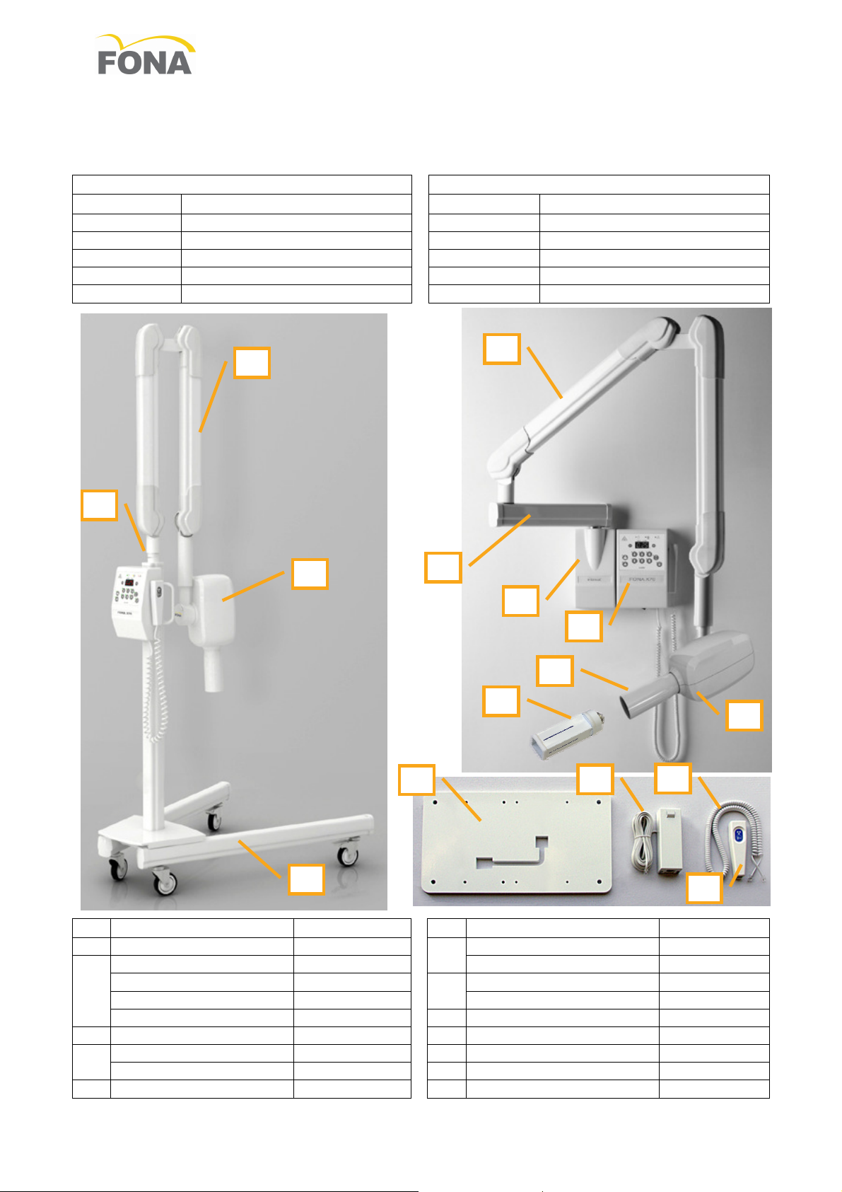
FONA X70
Systems at 230 V
FONA X70
Systems at 120 V
Code
Description
Code
Description
ID Description
Code
ID Description
Code
93 20
5 01300
93 20
5 01700
93 30
5 60200
93 30
5 60100
C
D
F
G
J
B
A
E
C
F
L
G
I
H
K
Appendix A
Systems and Components
97 576 62320 Wall Syst. Arm S 30 cm 230V 97 526 62320 Wall Syst. Arm S 30 cm 120V
97 576 62620 Wall Syst. Arm M 60 cm 230V 97 526 62620 Wall Syst. Arm M 60 cm 120V
97 576 62820 Wall Syst. Arm L 80 cm 230V 97 526 62820 Wall Syst. Arm L 80 cm 120V
97 576 62120 Wall Syst. Arm L 100 cm 230V 97 526 62120 Wall Syst. Arm L 100 cm 120V
97 576 67820 Mobile System 230V 97 526 67830 Mobile System 120V UL/CSA
A Wall adaptor 93 105 11000
B
C Scissor arm 93 150 12010 I 3x4 cm X-ray field BLD 91 300 00040
D
E Wall plate 16” 86 100 11500 L Kit remote hand-switch 93 300 02000
10/16 69 500 70110 110720
X-ray head 7 mA 120 V
Support arm S 30 cm 93 150 17100 X-ray head 7 mA 230 V
Support arm M 60 cm 93 150 17200
Support arm L 80 cm 93 150 17300 AutoSet Timer 220-240 V
Support arm L 100 cm 93 150 17400 H 6 cm circular field BLD 91 300 00020
Mobile stand 93 150 20080 J Coiled cable 76 190 25580
Mobile stand UL/CSA 93 150 20090 K Hand-switch W/O cable 76 190 25590
F
AutoSet Timer 110-120 V
G
Page 11
FONA X70 – Operating Instructions
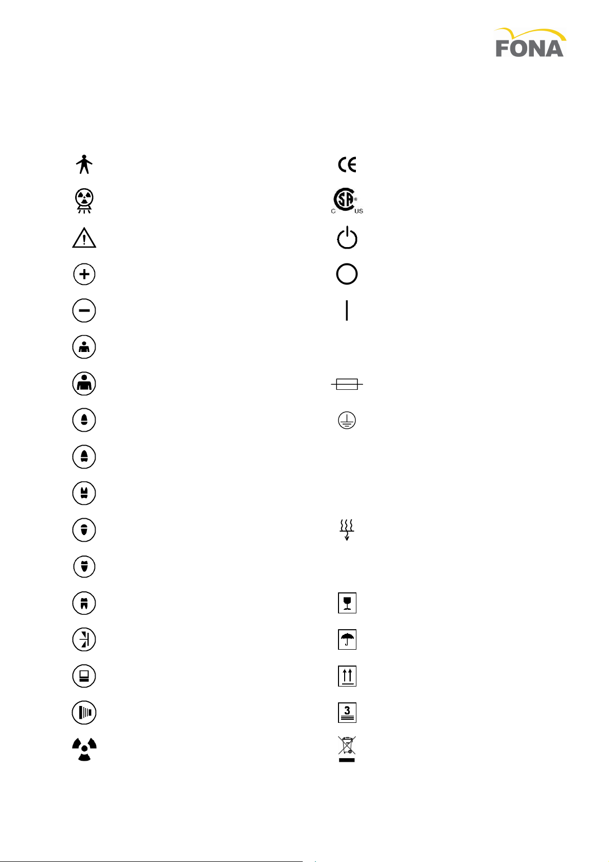
Appendix B
Icons
IEC Type B
Equipment
X-ray On
Irradiation
Examine Annexed Documentation
Increase Exposure Time (one step)
Decrease Exposure Time (one step)
Child – Small Patient
Adult – Large patient
Upper Incisor
Upper Canine/Premolar
~
N
Compliance to European Community
Requirements
Compliance to Canadian and US
Standards
Line voltage supply On - System
Ready
Off (Disconnected from Line voltage
Supply)
On (Connected to Line voltage Supply)
Alternate Current
Fuse
Protective Earth
Neutral Point (for equipment permanent connected to line)
Upper Molar
Lower Incisor
Lower Canine/Premolar
Lower Molar
Bite Wing - Interproximal
Digital Receptor
Radiography Push Button
Ionizing Radiation
L
g
Live Point (for equipment permanent connected to line)
Inherent Filtration
Focal Spot
Fragile,
Handle With Care
Fear of Humidity
Up
Do Not Overturn
Stacking Limit
Separate Collection,
Do Not Dispose
110720 69 500 70110 11/16
Page 12
FONA X70 – Operating Instructions
3,20
2,50
2,00
2,60
1,25
1,00
0,80
0,64
0,50
0,40
0,32
2,50
2,00
2,60
1,25
1,00
0,80
0,64
0,50
0,40
0,32
0,25
2,00
2,60
1,25
1,00
0,80
0,64
0,50
0,40
0,32
0,25
0,20
Upper
Molar
1,60
1,25
1,00
0,80
0,64
0,50
0,40
0,32
0,25
0,20
0,16
Upper
/Canine
Lower
Molar
1,25
1,00
0,80
0,64
0,50
0,40
0,32
0,25
0,20
0,16
0,12
Lower
/Canine
1,00
0,80
0,64
0,50
0,40
0,32
0,25
0,20
0,16
0,12
0,10
Lower
Incisor
0,80
0,64
0,50
0,40
0,32
0,25
0,20
0,16
0,12
0,10
0,08
0,64
0,50
0,40
0,32
0,25
0,20
0,16
0,12
0,10
0,08
0,06
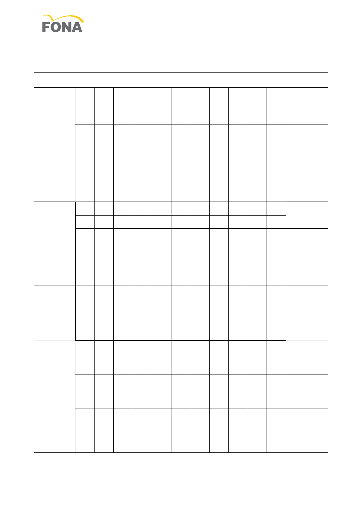
Appendix C
Exposure Table
FONA X70 - 70 kVp, 7 mA - Exposure Times in s
Small Pa-
tient
21cm
Focus-Film Distance
D Film
D Film
E Film
E Film
Digital
Digital
Large
Patient
D Film
E Film
Digital
Premolar
Bite Wing
Premolar
31 cm
Focus-Film Distance
D Film
D Film
D Film
E Film
E Film
E Film
Digital
Digital
Digital
Upper
Incisor
Small
Patient
Large Pa-
tient
12/16 69 500 70110 110720
Page 13
FONA X70 – Operating Instructions
X-ray requested
period
Green lamp
ing
By acknowledgement
system cooled down
Green lamp (System
(Alarm) flashing
Automatically when
range
Green lamp (System
(Alarm) flashing
Automatically when
range
System Ready (green)
lamp flashing
Exposure push bu
t-
power on
Exposure i
n-
By acknowledgement
m
Exposure stopped
mer
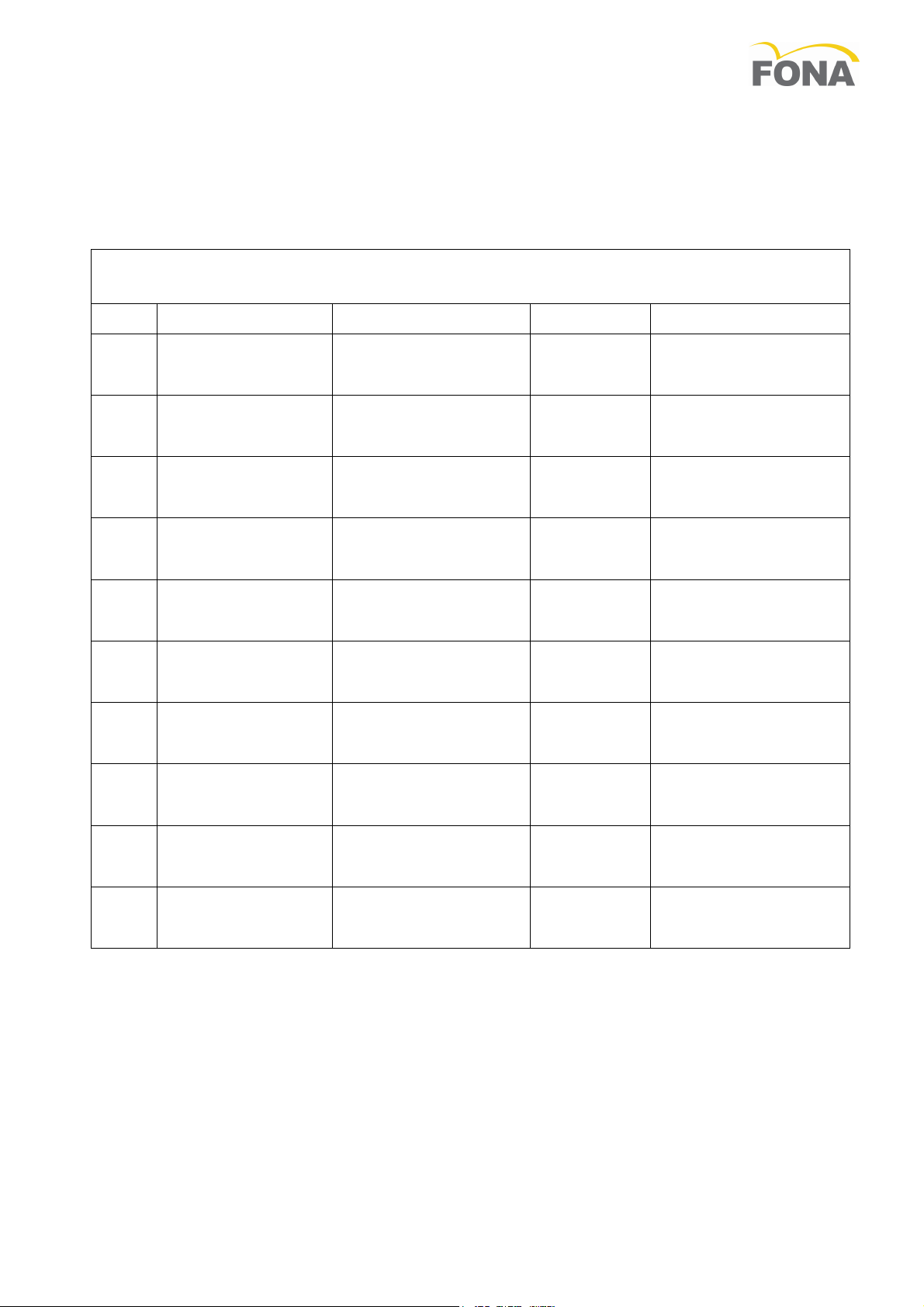
Appendix D
Alarm Conditions
AutoSet Timer Alarm Conditions
Code Fault /Error Signal Action Reset
A 01
A 02
A 03
A 06
A 07
A 08
A 99
A 10
during cool-down
Line voltage below
lower limit
Line voltage above
upper limit
Line Frequency Detection Failure
ton pressed at
Exposure stopped
by the operator
by the back-up ti-
Back-up relay failure
(System Ready) flash-
Ready) and red lamp
Ready) and red lamp
lamp and Alarm (red)
Red lamp
(Alarm) flashing
Red lamp
(Alarm) flashing
Red lamp (Alarm)
switched on
Red lamp (Alarm)
switched on
System inhibited
System inhibited
System inhibited
System inhibited
hibited
System inhibited
System inhibited
System inhibited
on the panel or when
line voltage back in
line voltage back in
By switching system
off and on again
By acknowledgement
on the panel
on the panel or after 1
By switching system
off and on again
By switching system
off and on again
A 11
A12
Power switching
device failure
Line dips during
exposure
Red lamp (Alarm)
switched on
Red lamp (Alarm)
switched on
System inhibited
Exposure inhibited
By switching system
off and on again
By acknowledgement
on the panel
110720 69 500 70110 13/16
Page 14
FONA X70 – Operating Instructions
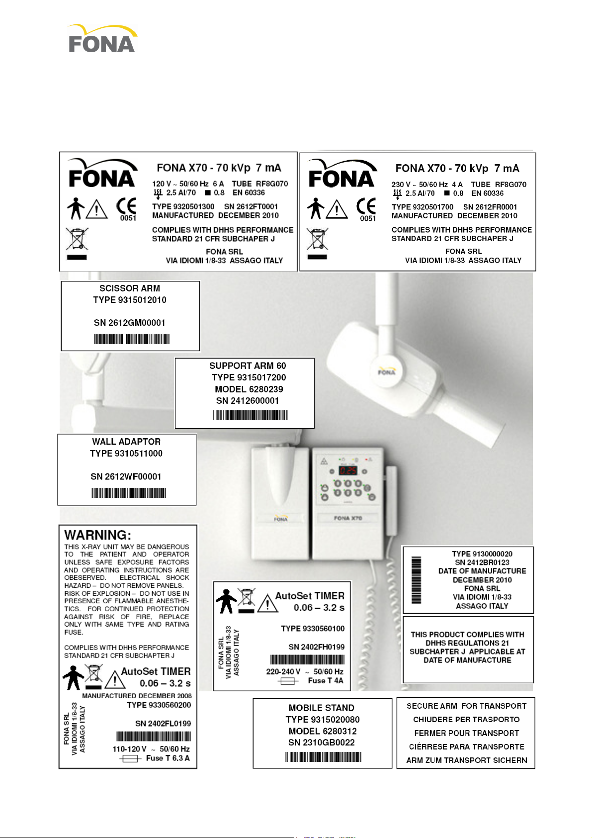
Appendix E
Identification Labels
14/16 69 500 70110 110720
Page 15
FONA X70 – Operating Instructions
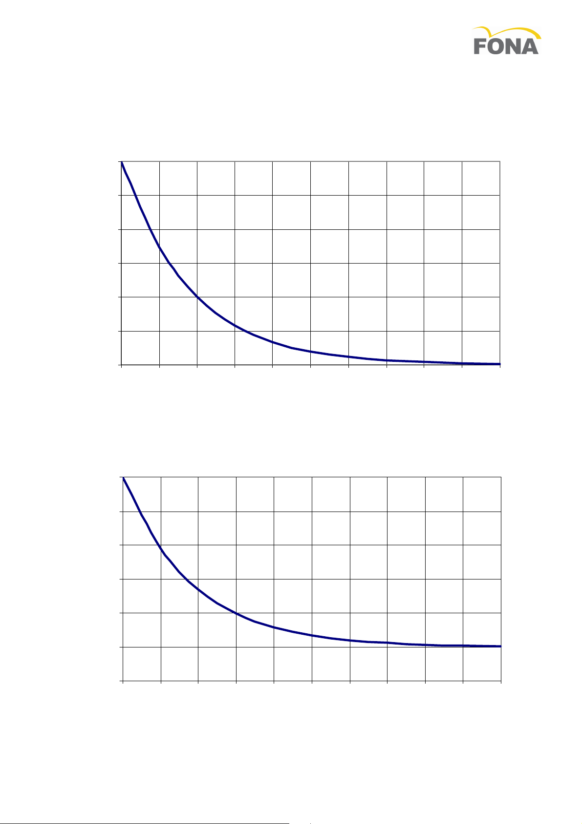
COOLING CURVE OF
X-RAY INSERT
T
ime
(min)
T
ime
(min)
Cooling Curves
kJ
kJ
6
5
4
3
2
1
0
0 0,5 1 1,5 2 2,5 3 3,5 4 4,5 5
COOLING CURVE OF TUBE HOUSING ASSEMBLY
150
125
100
75
50
25
0
0 20 40 60 80 100 120 140 160 180 200
Appendix F
110720 69 500 70110 15/16
Page 16

FONA Dental s.r.o.
FONA S.r.l.
*69
50070
110*
FONA X70 Operating Instructions – English Edition 110720
Stefanikova 7 SK-811 06
Bratislava, Slovakia
www.fonadental.com
Via Idiomi 1/8-33 - 20090
Assago (MI) Italy
 Loading...