

Fomotech TWISTER2XA5000 User Manual

TTAABBLLEE OOFF CCOONNTTEENNTTSS
Page
1. INTRODUCTION ....................................................................................................... 2
2. SAFETY INSTRUCTIONS ......................................................................................... 3
3. SYSTEM FUNCTIONS ............................................................................................. 4~6
4. TRANSMITTER OUTLINE
4.1 TRANSMITTER BOX ....................................................................................... 7
4.2 DETAI LED PARTS ............................................................................................. 7
4.3 ENCODER BOARD AND PLL MODULE ....................................................... 8
4.4 CHARGE, BATTERY AND WAIST BELT ....................................................... 8
5. RECEIVER OUTLINE
5.1 RECEIVER BOX ............................................................................................... 9
5.2 DETAILED PARTS ............................................................................................. 9
5.3 SHOCK ABSORBERS ....................................................................................... 10
5.4 RX MODULE CARD, DECODER CARD,
RELAY CARD, POWER SUPPLY CARD ......................................................... 10~12
6. SYSTEM SETTINGS
6.1 TRANSMIITTER ID CODE SETTINGS ........................................................... 13
6.2 TRANSMITTER FREQUENCY CHANNEL SETTINGS ............................... 13
6.3 TRANSMITTER SPECIAL FUNCTIONS SETTINGS ..................................... 13
6.4 FREQUENCY CHANNEL TABLE ................................................................... 14
6.5 RECEIVER LCD OUTLINE ............................................................................... 15
6.6 RECEIVER ID CODE AND FREQUENCY CHANNEL SETTINGS ............... 16
7. RECEIVER SYSTEM STATUS DISPLAYS ............................................................... 17~18
8. RECEIVER INSTALLATION
8.1 PREPARATION ................................................................................................. 19
8.2 STEP BY STEP INSTALLATION ..................................................................... 19
8.3 SYSTEM TESTING ........................................................................................... 20
9 OPERATING INSTRUCTION
9.1 POWER “ON” THE SYSTEM ........................................................................... 21
9.2 TRANSMITTER SYSTEM STATUS DISPLAYS ............................................... 21~22
10. BATTERY CHARGING ............................................................................................. 23
11. SYSTEM SPECIFICATIONS ..................................................................................... 24~25
1

11.. IINNTTRROODDUUCCTTIIOONN
The Twister 2X is a highly sophisticated industrial radio control system. The versatile
features of the Twister 2X permits a wide range of industrial applications. The Twister 2X
industrial radio control system can be used to control all types of cranes, building
construction equipment, automatic control systems, mining equipment, and many others.
The Twister 2X incorporates numerous safety circuits that guaranty maximum security and
ensure the system is resistant to other radio interference. The major features of the Twister
2X industrial radio control system is as follow:
* Highly evolved software that have redundant error checking and correcting capabilities
to ensure 100% error-free transmission, decoding, and control of output relays. These
software designs include CRC (Cyclical Redundancy Check Code) and Hamming
Codes (Error Recovery).
* The encoding system utilizes an advanced microprocessor for 100% error -free data
transmission. The availability of 65,536 sets of unique security ID codes will ensure
that only commands from the matching control transmitter can be carried out without
any interference from other radio systems.
* The decoding system utilizes dual advanced microprocessors, which ensures 100%
error-free calculation, bit checking, and correction of incoming transmitted data.
* The system also utilizes an additional central microprocessor for data comparison and
cross checking between the two decoding microprocessors to ensure 100% error-free
decoding and control of all output relays. When faults are detected via this central
microprocessor, for maximum safety, the entire system will be shutdown within 0.50
second to avoid any undesired crane movements.
* The system utilizes PLL synthesized RF for means of data transmission. It allows the
user to select from a wide range of frequency channels best suited for the environment.
The frequency channel is selected via a dip-switch in the transmitter unit and LCD
control panel in the receiver box. The receiver system also has the ability to auto scan
from a wide range of frequency channels. The receiver system will search and locked
on to the intended matching transmitter unit.
* Optional dual advanced receiving system for optimum receiving capability.
* The Twister 2X systems are equipped with numerous self-diagnosing features.
These include transmitter low voltage detection warning system automatic
shutdown, faulty pushbutton and joystick contact switches detection, faulty MAIN
contact relay detection, faulty relay boards detection, faulty EEPROM detection,
faulty PLL synthesizes RE unit detection, and incorrect security ID code detection.
2

22.. SSAAFFEETTYY IINNSSTTRRUUCCTTIIOONNSS
The Twister 2X system is relatively simple to use. However, it is very important to observe
the proper safety procedures during ope ration. When use properly the Twister 2X systems
will enhance productivity and efficiency in the workplace.
The following instructions should be strictly followed:
1. Make a daily check of the transmitter casing, joysticks, and pushbuttons. Should it
appear that anything could inhibit the proper operation of the transmitter unit, it should
be immediately removed from service.
2. The transmitter voltage should be checked on a daily basis. If the voltage is low, the
battery pack should be recharged or replaced.
3. The emergency stop pushbutton (EMS) should be checked at the beginning of each shift
to ensure they are in the proper working order.
4. In the event of an emergency, activate the emergency stop pushbutton immediately.
Then turned the power “off” from the main power source of the equipment.
5. The power switch should be turned “off” after use and should never left the power “on”
when the unit is unattended.
6. Do not use the same RF channel and ID code as any other unit in use at the same
facility (within 300 -meter range / 900 feet).
7. Ensure the waist belt is worn at all time during operation to avoid accidental dropping.
8. Never operate a crane or equipment with two (2) transmitter units at the same time with
same RF channel and ID code.
This device complies with Part 15 of the FCC Rules. Operation is
subject to the following two conditions: (1) this device may not cause
harmful interference, and (2) this device must accept any interference
received, including interference that may cause undesired operations.
Changes or Modifications not expressly approved by the party responsible
for compliance could void the users’ authority to operate the device.
3

33.. SSYYSSTTEEMM FFUUNNCCTTIIOONNSS
TTrraannssmmiitttteerr JJooyyssttiicckk
Each transmitter unit is equipped with up to two (2) joysticks with single or double axis per
joystick. Please see the table below for different joystick settings:
TYPE FUNCTION
Linear (step -less)
1-Speed No acceleration.
2-Speed Shared acceleration relay.
2-Speed Separate acceleration relay.
2-Speed
3-Speed Shared acceleration relay.
4-Speed Shared acceleration relay.
5-Speed Shared acceleration relay.
0-Speed Contact Relay
Note A: When 2nd speed contact relay is activated, the 1st speed contact relay will be
deactivated.
Separate acceleration relay / 1st and 2nd speed relay interlocked (refer
to note A).
0-speed (neutral position) can also be equipped with contact relay for
connection to crane’s braking system.
4

TTrraannssmmiitttteerr PPuusshhbbuuttttoonnss
There are many different types of pushbuttons and switches available for the Twister 2X; please
refer to the chart below.
TYPE FUNCTION
1-Step Pushbutton Standard non-toggled pushbutton
2-Step Pushbutton Standard non-toggled pushbutton
Mechanical Toggle Pushbutton Standard toggled pushbutton
Electronic Toggle Pushbutton Resets itself when the transmitter unit is turned “off”
Rocker Switch 0-T (refer to note 1 & 2)
Rocker Switch 0-R (refer to note 1)
Rocker Switch R-0 (refer to note 1)
Rocker Switch T -0-T (refer to note 1 & 2)
Rocker Switch R-0-T (refer to note 1 & 2)
Rocker Switch T -0-R (refer to note 1 & 2)
Rocker Switch R-0-R (refer to note 1)
Selector Switch 0-T (refer to note 1 & 2)
Selector Switch 0-R (refer to note 1)
Selector Switch T -0-T (refer to note 1 & 2)
Selector Switch T -0-R (refer to note 1 & 2)
Selector Switch R-0-T (refer to note 1 & 2)
Selector Switch R-0-R (refer to note 1)
ON / OFF Pushbuttons
Note 1: 0 Original position.
T Maintain position (toggled).
R Retract to the 0-position (non-toggled).
Note 2: Pushbuttons, rocker switches, and selector switches with T (toggled) settings can
also have their contact relay in the receiver to stay a ctivated even if the transmitter
unit is turned “off”.
2 pushbuttons per set / interlocked / will reset to “off”
position when transmitter unit is turned “off”
5

EEmmeerrggeennccyy SSttoopp BBuuttttoonn ((EEMMSS))
In case of an emergency, press the Emergency Stop Button will immediately deactivates the
transmitter unit and the receiver MAIN Contact Relay.
PPoowweerr KKeeyy SSwwiittcchh
Key switch for activating the power of the transmitter unit (please refer to Fig. 2 on page 7).
SSttaarrtt PPuusshhbbuuttttoonn
After turning “on” the transmitter unit via power key switch, press the START pushbutton
will activate the receiver MAIN. After resetting the emergency stop button, pressing the
START pushbutton will also activate the receiver MAIN.
RReemmoovvaabbllee RReellaayy CCaarrddss
The special designed relay cards with main motherboard for future system expandability and
replacements.
AAuuttoo SSccaannnniinngg RReecceeiivveerr
When the transmitter unit’s frequency channel is changed, the receiver unit will search and
locked on to the intended matching transmitter unit.
OOppttiioonnaall FFeeaattuurreess
1. Pitch and Catch Mode – This feature allows two operators controlling one crane system
from opposite ends of a long travel.
2. Tandem Mode – This feature allows two operators controlling two crane systems
independently or one operator controlling two crane systems simultaneously.
3. Random Access – This function allows for up to eight operators randomly accessing
eight crane systems via an eight-position selector switch.
6

44.. TTRRAANNSSMMIITTTTEERR OOUUTTLLIINNEE
44..11
TTrraannssmmiitttteerr BBooxx
(Fig. 1)
44..22
DDeettaaiilleedd PPaarrttss
1. Power Status LED Display
2. Signal Status LED Display
3. Information Plate (engraved)
4. Left Joystick Rubber Boot
5. Right Joystick Rubber Boot
6. START Pushbutton
7. AUX/RES Pushbutton
8. AUX/RES Pushbutton
9. AUX/RES Pushbutton
10. Emergency Stop Button (EMS)
11. Power Key Switch (removable)
12. Battery Contact
13. System Information
14. Battery slot
MODEL
:
CHANNEL A B C
:
VOLTAGE
(Fig. 2)
:
BAND
:
POWER
:
S/NO.
:
m
RXWTX W
A
B C
9
8
7
6
5
4
3
V
2
MHz
1
0
7
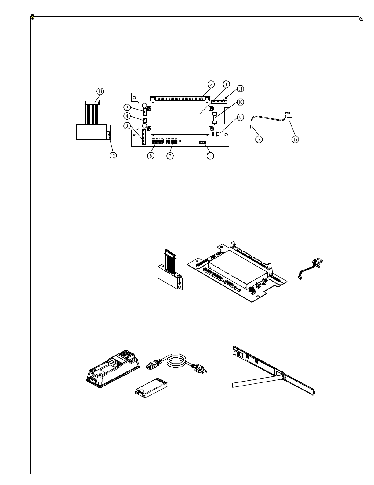
44..33 EEnnccooddeerr BBooaarrdd aanndd PPLLLL MMoodduullee
(Fig. 3)
1. Encoder Shield Plate 9. Power Key Switch Connector Port
2. Ribbon Type Connector Port 10. Power Fuse (0.25A)
3. Power Input Connector Port 11. Infrared Interface Port
4. Charger Connector Port 12. Antenna Port
5. TX Module Connector Port 13. TX module Connector
6. ID Code Dip-Switch 14. Power Key Switch Connector
7. Frequency Channel Dip-Switch 15. Power Key Switch
8. Programming Port
(Fig. 4)
44..44 IInntteelllliiggeenntt CChhaarrggeerr,, 660000mmAA BBaatttteerryy PPaacckk xx 22,,
p
WWaaiisstt BBeelltt,, aanndd SShhoouullddeerr SSttrraap
(Not Pictured)
(Fig. 5)
8
 Loading...