

Fomotech TWISTER2X User Manual

TTAABBLLEE O
OFF CC
ONNTTEENNTTSS
O
Page
1. INTRODUCTION ................................................................................................. 2
2. SAFETY INSTRUCTIONS ................................................................................... 3
3. SYSTEM FUNCTIONS
3.1 TRANSMITTER JOYSTICK DESCRIPTIONS ........................................... 4
3.2 TRANSMITTER PUSHBUTTON DESCRIPTIONS ................................... 5
3.3 GENERAL FUNCTION DESCRIPTIONS ................................................... 6
4. TRANSMITTER OUTLINE
4.1 TRANSMITTER EXTERNAL DESCRIPTIONS ......................................... 7
4.2 TRANSMITTER EXTERNAL DESCRIPTIONS ......................................... 8
5. RECEIVER OUTLINE
5.1 RECEIVER EXTERNAL & INTERNAL DESCRIPTIONS ......................... 9~11
5.2 RECEIVER MOUNTING DIMENSION ....................................................... 12
6. SYSTEM SETTINGS
6.1 TRANSMIITTER ID CODE SETTINGS ..................................................... 13
6.2 TRANSMITTER FREQUENCY CHANNEL SETTINGS ........................... 13
6.3 RECEIVER LCD STATUS DISPLAYS ......................................................... 14
6.4 RECEIVER ID CODE & FREQUENCY CHANNEL SETTINGS ............... 15
6.5 FREQUENCY CHANNEL TABLE ............................................................... 16
7. RECEIVER SYSTEM STATUS DISPLAYS ......................................................... 17~18
8. RECEIVER INSTALLATION
8.1 PREPARATION ............................................................................................. 19
8.2 STEP-BY-STEP INSTALLATION ................................................................. 19
8.3 SYSTEM TESTING ....................................................................................... 20
9. OPERATING INSTRUCTION
9.1 POWER “ON” THE SYSTEM ....................................................................... 21
9.2 DUAL HOIST/TROLLEY OPERATION ..................................................... 22
9.3 TRANSMITTER SYSTEM STATUS DISPLAYS ........................................... 23
10. BATTERY CHARGING ....................................................................................... 24
11. SYSTEM SPECIFICATIONS ............................................................................... 25~26
12. PARTS LIST ........................................................................................................... 27
1

1. INTRODUCTION
The Twister 2X is a highly sophisticated industrial radio remote control system. The versatile
features of Twister 2X permit its usage in a wide range of industrial applications. The system can
be used to control all types of industrial cranes, tower cranes, building construction equipment,
automatic control systems, mining equipment, and many others.
The Twister 2X incorporates numerous advanced safety features and software programming that will
ensure maximum security and safety in the workplace. The major features of Twister 2X industrial
radio remote control system are as follow:
* The system is equipped with highly evolved software that has redundant error checking and
correcting capabilities to ensure 100% error-free transmission, decoding, and control of all
output relays. This highly evolved software includes CRC (Cyclical Redundancy Check) and
Hamming Codes (Error Recovery) programming.
* The encoding system utilizes advanced microprocessor control for 100% error-free data
transmission. The availability of 65,536 sets of unique security ID codes + 20 distinct RF
channels will ensure that only commands from a matching control transmitter can be carried out
without any interference from other radio systems.
* The decoding system utilizes dual-microprocessor control, which will ensure 100% error-free
calculating, bit checking and correcting of all incoming data.
* The system also utilizes an additional central microprocessor for data comparison and
crosschecking between the two decoding microprocessors. When faults are detected via this
central microprocessor, for maximum safety, the entire system will be shutdown immediately to
avoid possibility of any accidents occurring.
* The system utilizes PLL synthesized RF transmission. It allows the user to select from 20 sets
of frequency channels best suited for the environment. The frequency channel is selected via
simple dip-switch settings inside the transmitter unit. The frequency channel for the receiver
is selected via simple button setting on the receiver LCD control panel. The receiver also has
the ability to auto-scan from these 20 sets of frequency channels. The receiver will search and
locked on to the intended matching control transmitter.
* For added safety the receiver also utilizes dual Safety Relay for the receiver MAIN relay circuit.
If the receiver MAIN relay is defective (example: fails to open or close during operation or not
responding to a “Stop” command) a fault will be detected and the system will be shut down
immediately to avoid possibility of any accidents occurring.
* The Twister 2X is equipped with numerous self-diagnosing functions, which include transmitter
low-voltage detection/warning, faulty pushbutton/joystick detection, faulty safety MAIN relays
detection, faulty relay boards detection, faulty EEPROM detection, faulty RX module detection,
incorrect ID code detection, and receiver MAIN auto-deactivation when transmitter low-voltage
is detected, when encountering strong radio interference, and when the transmitter/operator is
out of receiving range.
2

2. SAFETY INSTRUCTIONS
The Twister 2X system is relatively simple to use. However, it is very important to observe the
proper safety procedures before, during, and after operation. When use properly the Twister 2X
systems will enhance productivity and efficiency in the workplace.
The following instructions should be strictly followed:
1. Make a daily check of the transmitter casing, joysticks and pushbuttons. Should it appear that
anything could inhibit the proper operation of the transmitter unit, it should be immediately
removed from service.
2. The transmitter voltage should be checked on a daily basis. If the voltage is low, the battery
pack should be recharged or replaced (refer to page 23 for battery power status LED display).
3. The emergency stop button (EMS) should be checked at the beginning of each shift to ensure
they are in the proper working order.
4. In the event of an emergency, activate the emergency stop button immediately by pressing the
red EMS button down. This will immediately disconnect the transmitter power and receiver
MAIN relays. Then turned the power “off” from the main power source of the equipment.
5. The transmitter power key, which is located on the right side of the transmitter box, should be
turned “off” after each use and should never left the power key in “on” position when the unit is
unattended.
6. Do not use the same frequency channel and ID code as any other unit in use at the same facility
or within distance of 300 meters.
7. Ensure the waist belt and the shoulder strap is worn at all time during operation to avoid
accidental damages to the transmitter box.
8. Never operate a crane or equipment with two (2) transmitter units at the same time with same
frequency channel and ID code.
3

3. SYSTEM FUNCTIONS
3.1 Transmitter Joystick Descriptions
All transmitter units are equipped with two joysticks, in single or double axis configurations. The
table below illustrates the number of steps or speeds available for the Twister 2X in relation to each
speed’s output contact relay configuration:
TYPE FUNCTION
1-Speed
2-Speed
2-Speed*
3-Speed
4-Speed
5-Speed
0-Speed**
1 speed output contact relay for both forward and reverse motion
(total of 2 output relays per axis or motion)
Shared 2
nd
speed output contact relay for each forward and
reverse motion (total of 3 output relays per axis or motion)
Separate 2
nd
speed output contact relay for each forward and
reverse motion (total of 4 output relays per axis or motion)
Shared 2
nd
and 3rd speed output contact relays for each forward
and reverse motion (total of 4 output relays per axis or motion)
Shared 2
nd
, 3rd and 4th speed output contact relays for each forward and
reverse motion (total of 5 output relays per axis or motion)
Shared 2
nd
, 3rd, 4th and 5th speed output contact relays for each forward
and reverse motion (total of 6 output relays per axis or motion)
Addition of 0-speed (neutral position) output contact relay for
connection to crane’s braking system
* Separate 2nd speed output contact relay - For travel motion that required individual output contact relay for the 2nd speed function
(example: hoist motion with dual motors).
** By adding a 0-speed output contact relay, when the joystick is at center or neutral position, this 0-speed relay will be energized.
This feature is best suited for cranes or equipment with special breaking system.
4

3.2 Transmitter Pushbutton Descriptions
There are many different types of pushbuttons and switches available for the Twister 2X, please refer
to the chart below.
TYPE FUNCTION
1-Step Pushbutton Pushbutton with momentary output contact relay
1-Step Electronic Toggled Pushbutton
Mechanical T oggled Pushbutton
2-Stage Mechanical Rocker Switch 0-T (refer to note 1 & 2)
2-Stage Mechanical Rocker Switch 0-R (refer to note 1)
3-Stage Mechanical Rocker Switch T-0-T (refer to note 1 & 2)
3-Stage Mechanical Rocker Switch R-0-T (refer to note 1 & 2)
3-Stage Mechanical Rocker Switch T-0-R (refer to note 1 & 2)
3-Stage Mechanical Rocker Switch R-0-R (refer to note 1)
2-Stage Mechanical Selector Switch 0-T (refer to note 1 & 2)
2-Stage Mechanical Selector Switch 0-R (refer to note 1)
3-Stage Mechanical Selector Switch T-0-T (refer to note 1 & 2)
Resets itself when the transmitter unit is turned
“off” or when EMS button is activated
Maintained toggled even after transmitter unit is turned
“off” or when EMS button is activated
3-Stage Mechanical Selector Switch T-0-R (refer to note 1 & 2)
3-Stage Mechanical Selector Switch R-0-T (refer to note 1 & 2)
3-Stage Mechanical Selector Switch R-0-R (refer to note 1)
“ON/OFF” 1-Step Pushbuttons
Note 1: 0 → Neutral position.
T → Maintained position (toggled contact).
R → Retract back to 0-position (momentary contact).
Note 2: 1-step pushbuttons, 2 & 3 stage mechanical rocker and selector switches with maintained toggled function (T) will remained
energized (or closed) even when the power of the transmitter is turned off or when EMS is activated (Receiver Hold function).
Will reset to “off” position when transmitter unit is
turned “off” or after EMS reset
5

3.3 General Function Descriptions
Emergency Stop Button (Standard Equipped)
In case of an emergency, press down the red emergency stop button (EMS) will immediately
deactivates the transmitter power and the receiver safety MAIN contact relays (refer to section 4.1 on
page 7).
Transmitter Power Key (Standard Equipped)
All transmitters are equipped with two detachable power keys (one for spare) for turning the
transmitter power “on” and “off” (refer to section 4.1 on page 7).
START button (Standard Equipped)
All transmitters are equipped with a START button for purpose of activating the receiver MAIN
contact relay after turning on the transmitter power. After turning “on” the transmitter unit via the
transmitter power key, press and hold the START button for up to a second will activate the receiver
MAIN contact relay.
After resetting the EMS button, by twisting the button 1/4 turn clockwise, the operator must also
press and hold the START button for up to a second to reenergize the receiver MAIN contact relay.
Also, when the system is left unattended for 5 minutes or longer (system will go into sleep mode), the
operator must again press and hold the START button for up to a second to reenergize the receiver
MAIN contact relay.
Removable Relay Cards (Standard Equipped)
Special designed relay cards provided easy service maintenance and as well as for simplifying the
inventory of spare parts.
Auto-Scanning Receiver (Standard Equipped)
When transmitter’s frequency channel (from channel 01 ~ 20) is changed via simple dip-switch
setting inside the transmitter belly box, the receiver will search and locked on to the intended
matching transmitter.
Tandem Feature / Dual-Crane Operation Feature (optional)
This feature allows two operators controlling two crane systems independently or one operator
controlling two crane systems simultaneously (Crane A, Crane B, Crane A+B).
“Pitch And Catch” Feature (optional)
This feature allows two operators controlling one crane system from opposite ends of a long or cross
travel.
Random Access Feature (optional)
This feature allows for up to 8 operators randomly accessing up to 8 crane systems via a 16-position
mechanical selector switch and operate pitch/catch function via START/PITCH button.
Infrared Initial Startup Feature (optional)
The feature allows system activation under or in close proximity to the crane or receiver via infrared
transmission. After infrared initial system activation, the frequency transmission will take over.
6
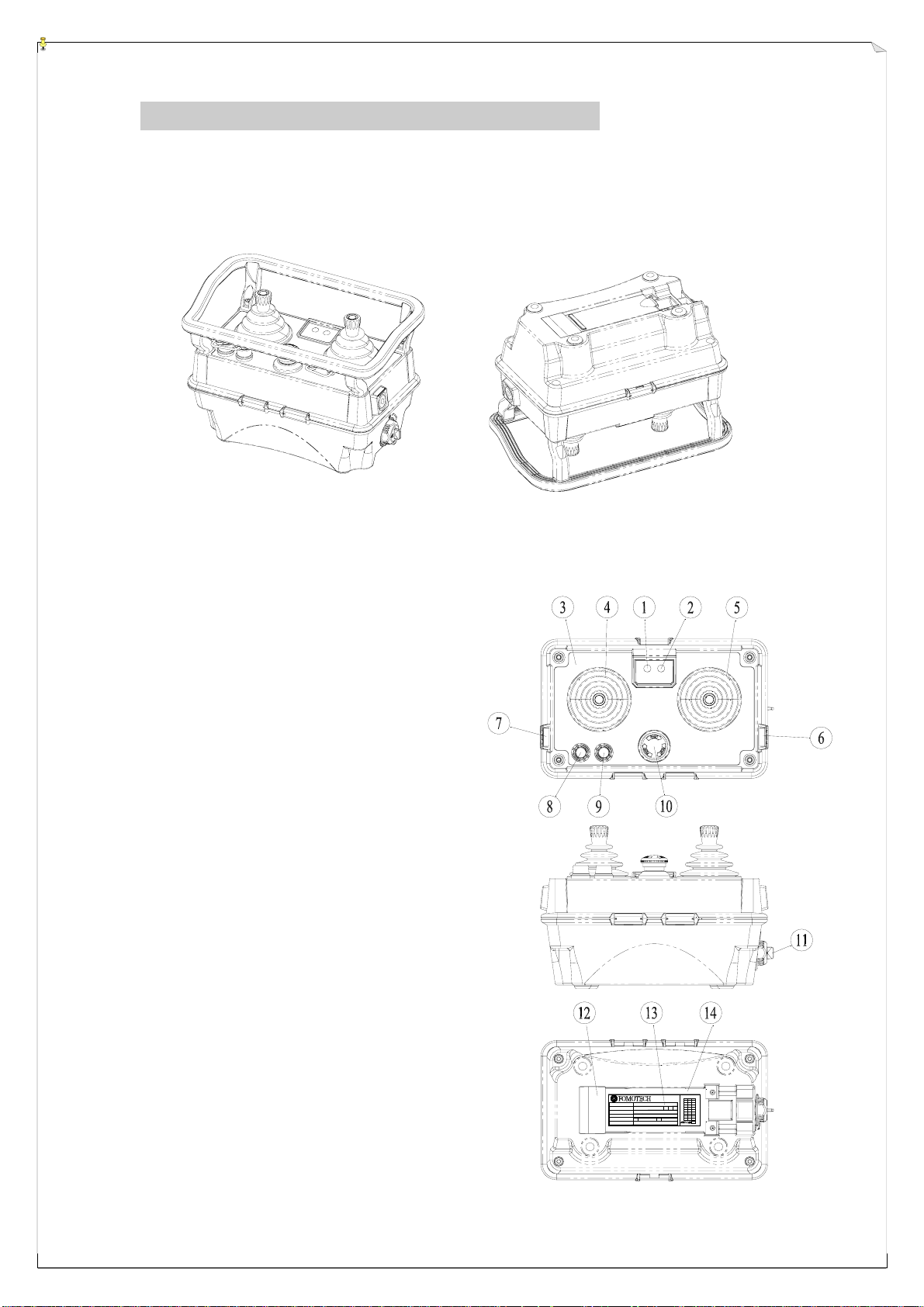
4. TRANSMITTER OUTLINE
4.1 Transmitter External Descriptions
(Fig. 1) Transmitter Top View (Fig. 2) Transmitter Bottom View
1. Battery Power LED Display
2. Status LED Display
3. Information Top Plate (engraved)
4. Left Joystick
5. Right Joystick
6. START Pushbutton
7. AUX/RES Pushbutton (side panel)
8. AUX/RES Pushbutton (top panel)
9. AUX/RES Pushbutton (top panel)
10. Emergency Stop Button (EMS)
11. Power Key (detachable)
12. Battery Contact (gold-plated)
13. System Information
14. Battery slot
MODEL
:
:
CHANNEL A B C
:
VOLTAGE
:
(Fig. 3) Transmitter Exterior Views
BAND
:
POWER
:
S/NO.
A
9
8
7
6
5
4
V
3
2
MHz
1
0
m
RXWTXW
BC
7
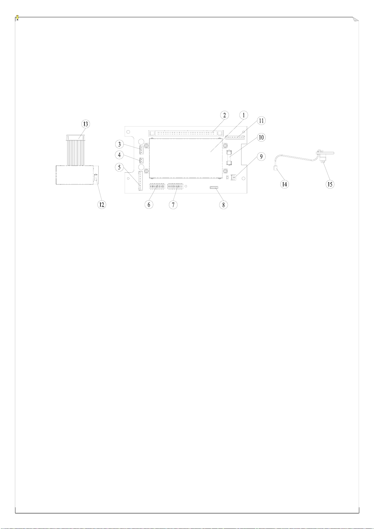
4.2 Transmitter Internal Descriptions
(Fig. 4) RF Module, Encoder Board and Power Switch Views
1. Encoder Shielding Plate 9. Power Key Switch Connector Port
2. Ribbon Type Connector Port 10. Power Fuse (0.5A)
3. Power Input Connector Port 11. Infrared Startup Interface Port
4. Charger Connector Port 12. Antenna Port
5. TX Module Connector Port 13. TX module Connector
6. ID Code Dip-Switch 14. Power Key Switch Connector
7. Frequency Channel Dip-Switch 15. Power Key Switch
8. External Programming Port
8
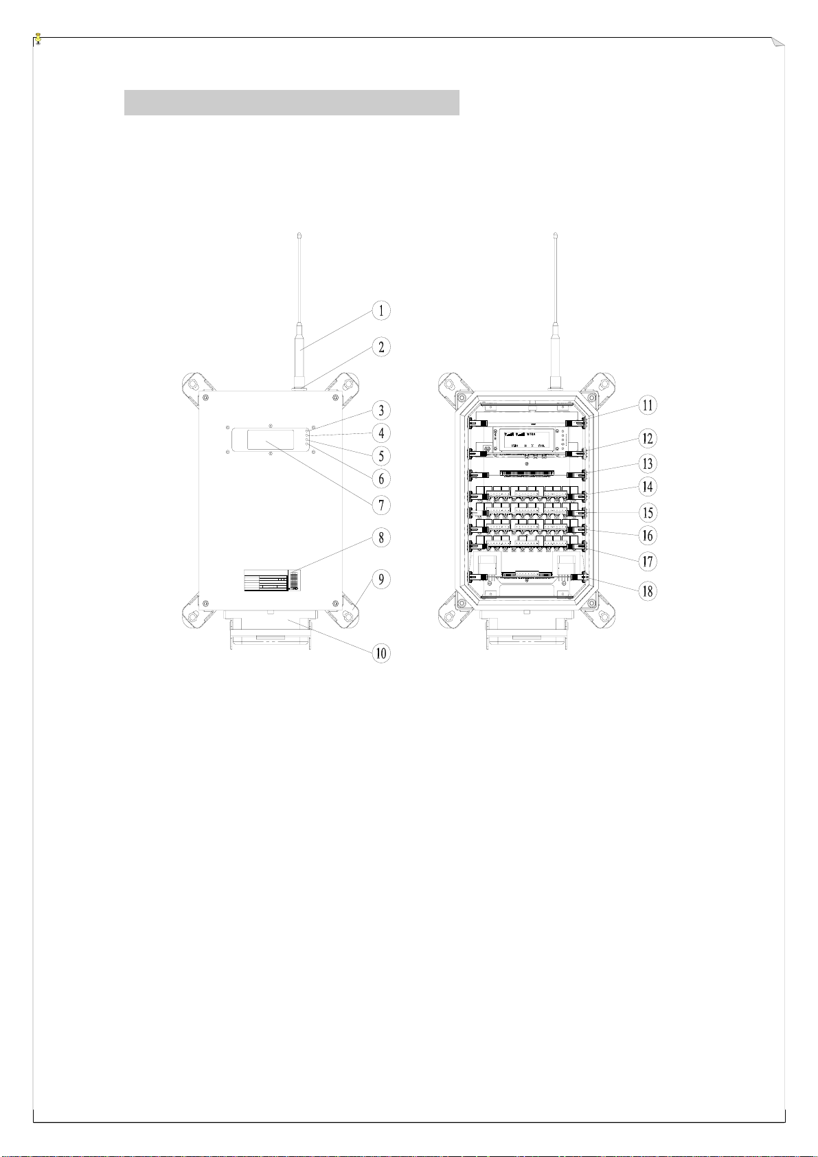
5. RECEIVER OUTLINE
5.1 Receiver External and Internal Descriptions
>>>>>>
0000000000000000000000000000000000000000
F
TEC I T'P
MODEL
CHANNEL A B C
VOLTAGE
BAND
POWER
S/NO.
:
:
:
:
:
:
V
MHz
m
RXWTXW
A
BC
9
8
7
6
5
4
3
2
1
0
(Fig. 5) Receiver External and Internal View
1. Antenna 10. Multi-Pin Cable Connector (optional)
2. Antenna Port 11. RX Module Card
3. AC Power Display 12. Decoder Card
4. SQ-1 Display (for RX-1) 13. Reserved Relay Card Slot
5. SQ-2 Display (for RX-2 / optional) 14. Relay Card #1
6. Central CPU Status Display 15. Relay Card # 2
7. System LCD Display 16. Relay Card # 3
8. System Information Plate 17. Relay Card # 4
9. Mounting Bracket + Shock Absorber 18. Power Supply Card
9
 Loading...