

Fomotech Alpha 607ATS, Alpha 604AS, Alpha 604BS, Alpha 607BS, Alpha 607BTS Operations & Parts Manual
...
A
All
p
p
h
h
a
a
6
6
0
0
0
0
X
X
S
S
S
S
e
e
r
rii
e
e
s
s
IInndduussttrriiaall RRaaddiioo RReemmoottee CCoonnttrrooll SSyysstteemm
O
Oppeerraattiioonn
&
& PPaarrttss
M
Maannuuaall
Fomotech International Corp.

1
TTAABBLLEE OOFF CCOONNTTEENNTTSS
Page
1. SAFETY INSTRUCTION ............................................................................................. 3
2. PUSHBUTTON CONFIGURATION
2.1 Alpha 604 Models ..................................................................................... 4
2.2 Alpha 607 & 608 Models ..................................................................................... 5
2.3 Alpha 612 Models ............................................................................................... 5
3. TRANSMITTER OUTLINE
3.1 Transmitter Outline ..................................................................................... 6
3.2 Alpha 604/607/608/612 Spare Parts ...................................................................... 7
3.3 Charger Assembly ................................................................................................. 7
4. RECEIVER OUTLINE
4.1 Alpha 604-608
4.1.1 Alpha 604-608 Models External Assembly ....................................................... 8
4.1.2 Alpha 604 Models Internal Assembly ................................................................ 9
4.1.3 Alpha 607/607 Models Internal Assembly ......................................................... 10
4.2 Alpha 612
4.2.1 Alpha 612 Models External Assembly ............................................................. 11
4.2.2 Alpha 612 Models External/Internal Assembly ............................................... 12
4.3 Alpha 604/608/612 Receiver Power Fuse List ......................................................... 13
5. OUTPUT CONTACT DIAGRAMS
5.1 Alpha 604 Models Double Output............................................................................. 14
5.2 Alpha 607 Models Double Output........................................................................... 15
5.3 Alpha 608 Models Double Output........................................................................... 17
5.4 Alpha 612 Models Double Output........................................................................... 19
6. SYSTEM CONFIGURATIONS
6.1 How to Set ID Codes ............................................................................................. 26
6.2 Transmitter RF Channel Setting ............................................................................. 27
7. RECEIVER SETTING
7.1 How to Set α604/607/608/612
Receiver ID Codes ................................................ 27
7.1.1 How to set α604/607/608/612
Receiver ID Codes ........................................ 27
7.1.2 How to set α612 Receiver ID Code ............................................................... 28
7.2 Receiver RF Channel Setting .............................................................................. 28
7.3 Receiver Function Setting .............................................................................. 29
7.3.1 α604/607/608/612
Receiver Function Setting ................................................ 29
7.3.2 α612 Receiver Function Setting ..................................................................... 30
7.3.3 Alpha 612 Models Dip-Switch Function Table .............................................. 31
7.3.4 Alpha 612 Receiver Voltage Settings ............................................................. 33
7.4 Frequency (RF) Channels Table .............................................................................. 34
8. TRANSMITTER OPERATION & STATUS LIGHT
8.1 Transmitter Operating Steps .............................................................................. 35
8.2 Transmitter Status light .............................................................................. 36

2
9. RECEIVER INSTALLATION
9.1 Preparation For Installation ................................................................................... 37
9.2 Step-By-Step Installation ....................................................................................... 38
9.2.1 Select the location .......................................................................................... 38
9.2.2 Commissioning steps ..................................................................................... 38
9.3 System Testing ....................................................................................................... 39
9.4 Receiver System Status LED Display..................................................................... 39
10. BATTERY CHARGER
10.1 Charger Operation ................................................................................................. 41
10.2 Battery Charger LED Status Light ......................................................................... 42
11. TROUBLE SHOOTING................................................................................................. 43
12. SYSTEM SPECIFICATION ........................................................................................ 44
13. PARTS LIST ................................................................................................................. 46

3
1. SSAAFFEETTYY IINNSSTTRRUUCCTTIIOONN
The Alpha 600XS series are relatively simple to use, however, it is very important to observe the proper
safety procedures before, during, and after operation. When used properly, the Alpha 600XS series will
enhance safety, productivity and efficiency in the workplace.
The following procedures should be strictly followed:
1. The transmitter is equipped with an induction battery charger. Only two ”AA” Ni-MH rechargeable
batteries are allowed to be used in the transmitter. Please note the polarity of the batteries. Do not
use other types of battery to prevent any accident.
2. Be sure to replace the batteries with the same brand and specification at the same time. Do not
replace only one battery in the battery compartment otherwise there will have the condition of limited
transmitter operating time, battery leakage and overheating when charging.
3. Do not place the battery charger under the raining, high temperature, humid and with corroded air
environment. Indoor with good ventilation is suggested. Please also do not use the battery
charger under 0℃.
4. It is prohibited that the high power wireless equipment such as walkie-talkie, wireless network
transmitter, … etc. is closed to the transmitter or receiver as it might cause interference.
5. Do not change the IDs on transmitter encoder and receiver decoder boards at will.
6. Check the transmitter casing and pushbutton daily. Should any damage that could inhibit the proper
operation of the transmitter be found the unit should be immediately removed from services.
7. Check the transmitter voltage whenever it is operated. Place the transmitter into battery charger
when battery is running out or the voltage is low.
8. The red emergency stop button (EMS) should be checked at the beginning of each shift to ensure it is
in proper working order and the “Stop” command is being received by the receiver.
9. In the event of an emergency press down the EMS button will immediately deactivates the receiver
MAIN relay and the transmitter power. Then turned the power “off ” from the main power source to
the crane or equipment.
10. Do not use the same RF channel and ID code as any other system in use at the same facility or within
300-meter distance.
11. Ensure the waist belt is worn at all time during operation to avoid accidental damage to the
transmitter.
12. Rotate the power switch to OFF position when the transmitter is not operated temporarily or the
operation is finished.
13. Any repair or adjustment should be proceeding by repair technician for radio remote controls.
14. The operator should not change any electrical parts at will.
- 4 -
STOPPOWER
STOPPOWER
2. PPUUSSHHBBUUTTTTOONN CCOONNFFIIGGUURRAATTIIOONN
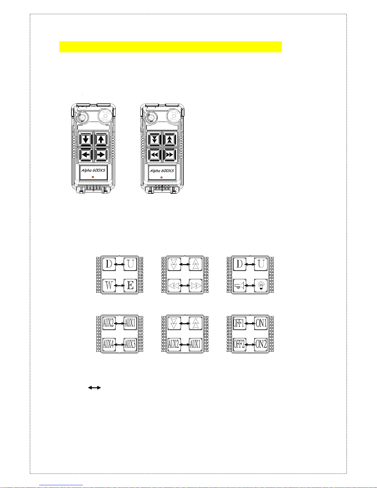
2.1 Alpha 604 Models
1. Alpha 604AS -- (4) single speed pushbuttons
2. Alpha 604BS -- (4) double speed pushbuttons
(Alpha 604AS) (Alpha 604BS)
Below are some of many types of pushbutton configurations that are also available, please contact your dealer
for more details.
Interlocked (Can also be set to non-interlocked via an external programmer unit).
STOPPOWER
上
下
西
東
FOM TECH
EN ISO 13849-1:2008, PLd
STOPPOWER
上
下
西
東
FOM TECH
EN ISO 13849-1:2008, PLd
- 5 -
STOPPOWER
STOPPOWER
STOPPOWER
STOPPOWER
STOPPOWER
STOPPOWER
STOPPOWER
STOPPOWER
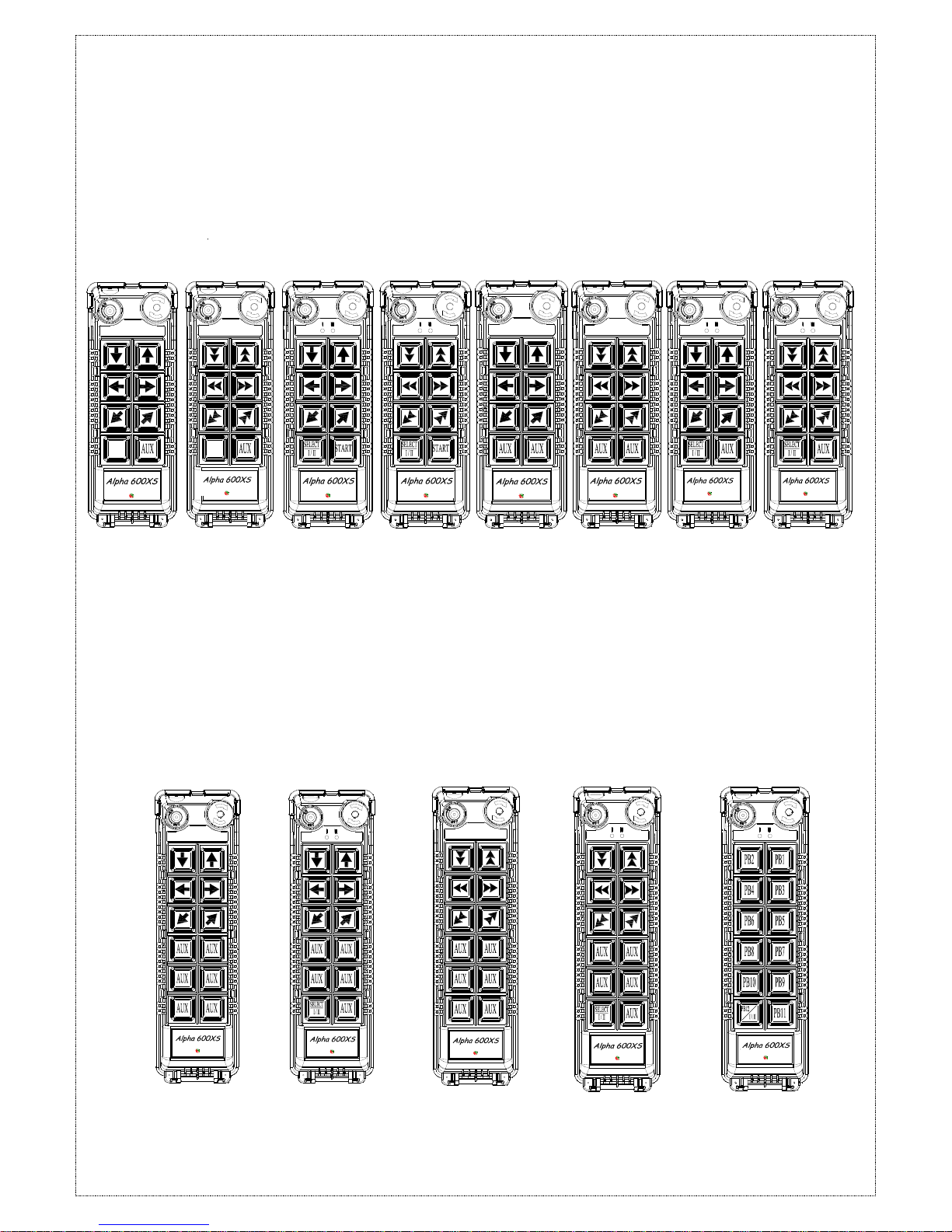
2.2 Alpha 607 & 608 Models
1. Alpha 607AS -- (7) single speed pushbuttons
2. Alpha 607BS -- (6) double speed pushbuttons + (1) single speed pushbuttons
3. Alpha 607ATS -- (6) single speed pushbuttons + (1) SELECT I/II pushbutton
4. Alpha 607BTS -- (6) double speed pushbuttons + (1) SELECT I/II pushbutton
5. Alpha 608AS -- (8) single speed pushbuttons
6. Alpha 608BS -- (6) double speed pushbuttons + (2) single speed pushbuttons
7. Alpha 608ATS -- (7) single speed pushbuttons + (1) SELECT I/II pushbutton
8. Alpha 608BTS -- (6) double speed pushbuttons + (1) single speed pushbuttons+ (1) SELECT I/II pushbutton
(Alpha 607AS) (Alpha 607BS) (Alpha 607ATS) (Alpha 607BTS) (Alpha 608AS) (Alpha 608BS) (Alpha 608ATS) (Alpha 608BTS)
2.3 Alpha 612 Models
1. Alpha 612AS -- (12) one-speed pushbuttons
2. Alpha 612BS -- (11) one-speed pushbuttons + I/II select pushbutton*
3. Alpha 612C-1S -- (6) two- speed + (6) one-speed pushbuttons
4. Alpha 612C-2S -- (8) two-speed + (4) one-speed pushbuttons
5. Alpha 612DS -- (10) two-speed + (2) one-speed pushbuttons
6. Alpha 612E-1S -- (6) two-speed + (5) one-speed pushbuttons + I/II select pushbutton*
7. Alpha 612E-2S -- (8) two-speed + (3) one-speed pushbuttons + I/II select pushbutton*
* For cranes with auxiliary hoist and trolley (changeover function).
Alpha 612C-1S
Alpha 612C-2S
Alpha 612DS
Alpha 612E-1S
Alpha 612E-2S
Alpha 612AS
Alpha 612BS
STOPPOWER
STOPPOWER
STOPPOWER
STOPPOWER
STOPPOWER
Alpha 612 button
reference
STOPPOWER
上
下
西
東
FOM TECH
EN ISO 13849-1:2008, PLd
STOPPOWER
上
下
西
東
FOM TECH
EN ISO 13849-1:2008, PLd
STOPPOWER
上
下
西
東
FOM TECH
EN ISO 13849-1:2008, PLd
STOPPOWER
上
下
西
東
FOM TECH
EN ISO 13849-1:2008, PLd
STOPPOWER
上
下
西
東
FOM TECH
EN ISO 13849-1:2008, PLd
STOPPOWER
上
下
西
東
FOM TECH
EN ISO 13849-1:2008, PLd
STOPPOWER
上
下
西
東
FOM TECH
EN ISO 13849-1:2008, PLd
STOPPOWER
上
下
西
東
FOM TECH
EN ISO 13849-1:2008, PLd
STOPPOWER
上
下
西
東
FOM TECH
EN ISO 13849-1:2008, PLd
STOPPOWER
上
下
西
東
FOM TECH
EN ISO 13849-1:2008, PLd
STOPPOWER
上
下
西
東
FOM TECH
EN ISO 13849-1:2008, PLd
STOPPOWER
上
下
西
東
FOM TECH
EN ISO 13849-1:2008, PLd
STOPPOWER
上
下
西
東
FOM TECH
EN ISO 13849-1:2008, PLd
- 6 -
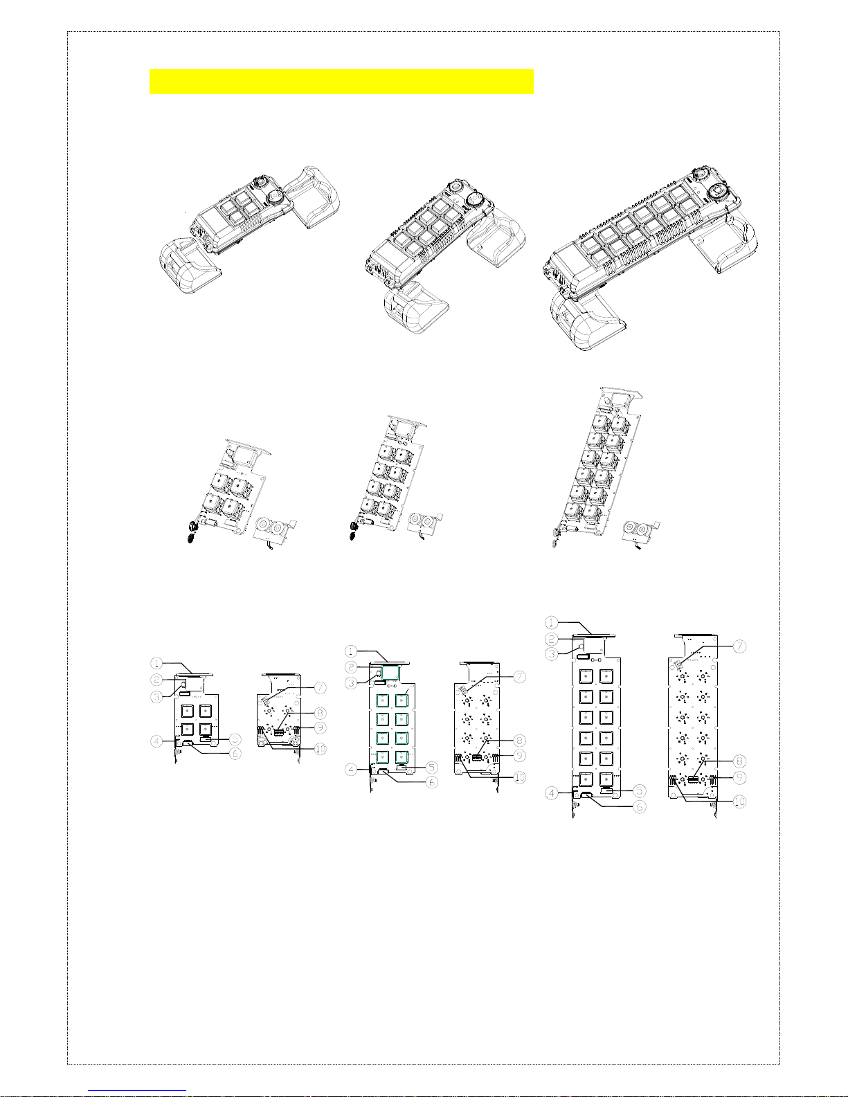
33.. TTRRAANNSSMMIITTTTEERR OOUUTTLLIINNEE
3.1 Transmitter Outline
(Alpha 604)
(Alpha 607/608)
(Alpha 612)
(Fig.1) Transmitter Front View
(Fig.2) Transmitter encoder board and induction charging board
(Fig.3) Transmitter Internal Assembly
(1) Internal antenna
(6) Programming port
(2) Transmitting RF module
(7) E-stop connecting port
(3) Status LED display
(8) Function dip-switch
(4) Battery contact
(9) JP2 setting pin
(5) Transmitter induction
charging port
(10) JP1 setting pin
- 7 -
1
2
3-2
3-1
4
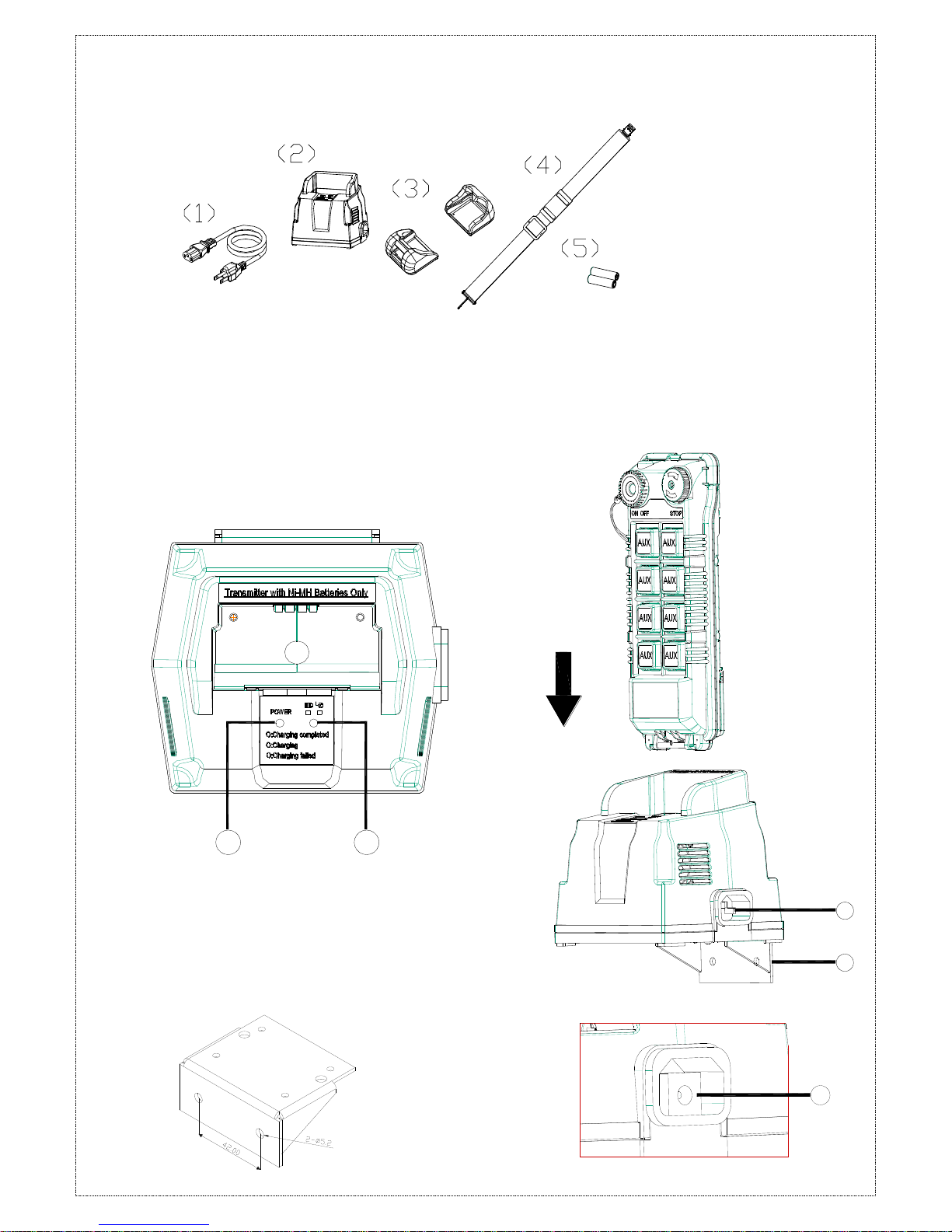
3.2 Alpha 604/607/608/612 Spare Parts
3.3 Charger Assembly
(1) Charger power status: green light
(2) Charging status: green/red light
(3-1) Power input socket AC100-240V
(3-2) Power input socket DC12-24V
(4) Charger holder (optional). Please refer to
below figure for the installation holes.
(1) Charging cable
(2) Charger (charging cable included, optional)
(3) Transmitter shock-absorbing rubber
(4) Shoulder strap
(5) Rechargeable batteries (optional)
(Fig.4) Battery Charger
& Holder
- 8 -
44.. RREECCEEIIVVEERR OOUUTTLLIINNEE
44..11 AAllpphhaa 660044 ~~ 660088
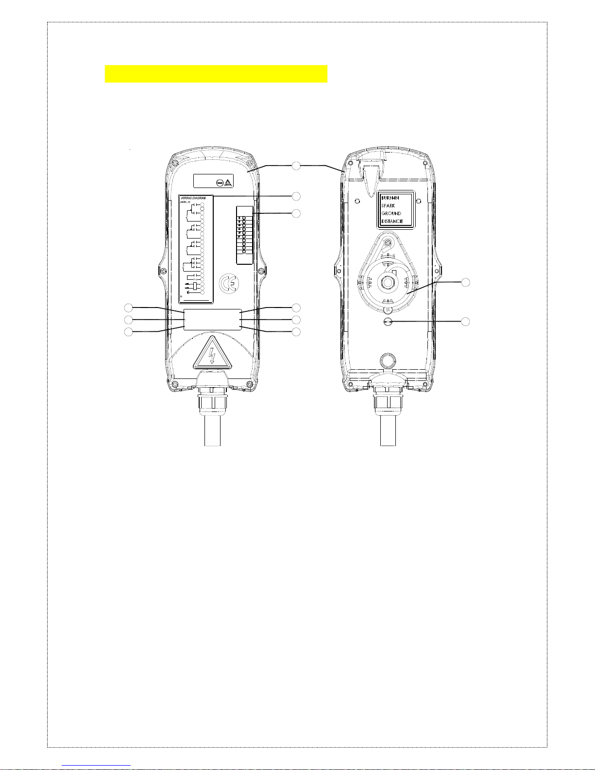
44..11..11 AAllpphhaa 660044 ~~ 660088 MMooddeellss EExxtteerrnnaall AAsssseemmbbllyy
SIZE:310mm X 134mm X 72mm
AC
SQ
M
A
W
S
N
E
U
D
AC
SQ
M
A
VOLT :
CH:
MOD:
S/ N:
FRE Q:
ID:
FILTER
Anti-vibration spring
must be grounded
POWER
MAIN
F6
5A
F1
F5 5A
LV/AUX1
COM4
17
L2(X2)
L1(X1)
GRN/YEL
COM5
MAIN
22
FF1
21
20
18
19
AUX1
AUX2
NC
COM3
NC
COM2
15
16
14 LV
N1
S1
COM1
D1
W1
E1
NC
NC
U1
F4 5A
F3 5A
13
10
11
12
9
8
3
5
6
7
4
F2 5A
2
1
BRIDGE
TROLLEY
HOIST
/AUX2
60947 EMS
EN ISO 13849-1:2008, PLd
1
2
3
7
8
9
4
5
6
11
10
(Fig.5) Front View (Fig.6) Back View
1) Receiver enclosure 5) System frequency 9) System serial number
2) Wiring diagram 6) Supplied voltage 10) Anti-vibration spring
3) Receiver LED displays* 7) System ID code 11) Grounding (GND)
4) Type model 8) System RF channel
* A ~ AUX Relay Contact Indicator (for Alpha 607A /608B models only).
* M ~ MAIN and 2nd Speed Relay Contact Indicator.
Green "on" → MAIN activated (All models).
Red "on" → 2nd speed activated (for Alpha 608B model only).
* SQ ~ RF Signal Indicator (Red).
"on" → RF signal detected and received.
"off" → No RF signal detected or received.
Blinking at transmitter power "off" → Other radio interference.
* AC ~ Power Source Indicator (red) "on" → AC input power supplied.
"off" → No AC input power.
- 9 -
1
8
11
10
12
13
17
18
9
15
20
FUSE
4
5
FUSE
FUSE
FUSE
14
FUSE
16
19
3
6
2
7
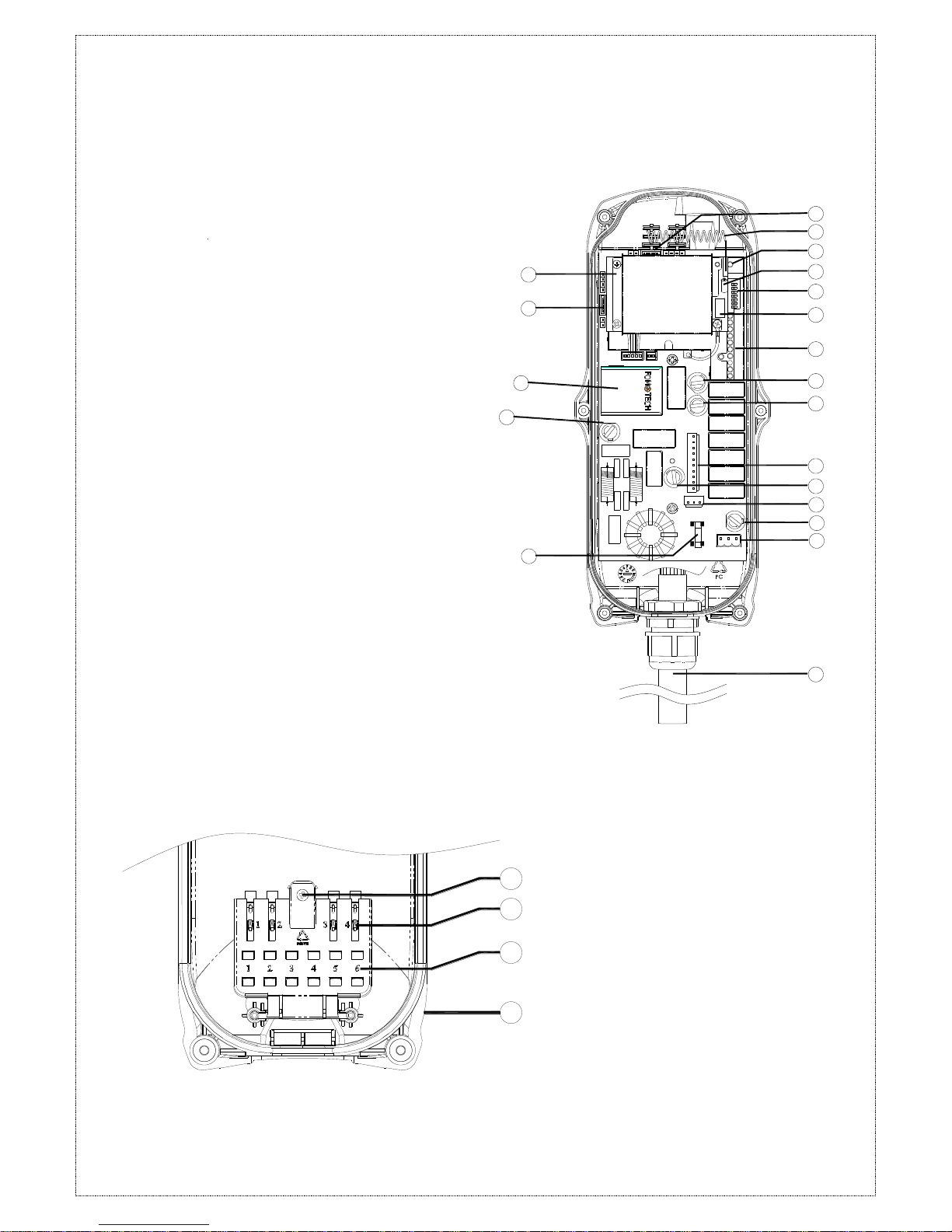
44..11..22 AAllpphhaa 660044 IInntteerrnnaall AAsssseemmbblly
y
(Fig. 7) Internal Parts Assembly
1) Receiving RF module
2) External programming port(CN5)****
3) Power module *
4) Secondary power AC fuse (F1)**
5) Primary power AC fuse (FF1)**
6) External programming port(CN9)****
7) Receiving antenna
8) System status LED display***
9) External antenna port
10) ID code dip-switch
11) RF channel dip-switch
12) Contact relay LED display
13) Pushbutton #1 and #2 fuse (5.0A)
14) MAIN fuse (5.0A)
15) Contact output seat (CN3)
16) Low-voltage (LV) fuse (5.0A)
17) Contact output seat (CN4)
18) Pushbutton #3 and #4 fuse (5.0A)
19) AC power input seat (CN2)
20) Cable gland & output cable
* Power module: Including transformer or full-voltage module.
** Please refer to 4.3 α604/α608/α612 Receiver Power Fuse List.
*** Please refer to page 40 for system status
LED display information.
*** For item 2 & 6, the receiver and country code / ID have to be set
at the same time.
1) Spare fuse & jumper compartment
2) Spare Jumper slots
3) Spare fuse slots
4) Receiver top casing
1
2
3
4
- 10 -
FUSE
FUSE
FUSE
1
2
10
5
13
12
14
15
16
17
19
20
11
18
22
FUSE
FUSE
FUSE
4
6
7
9
21
3
8
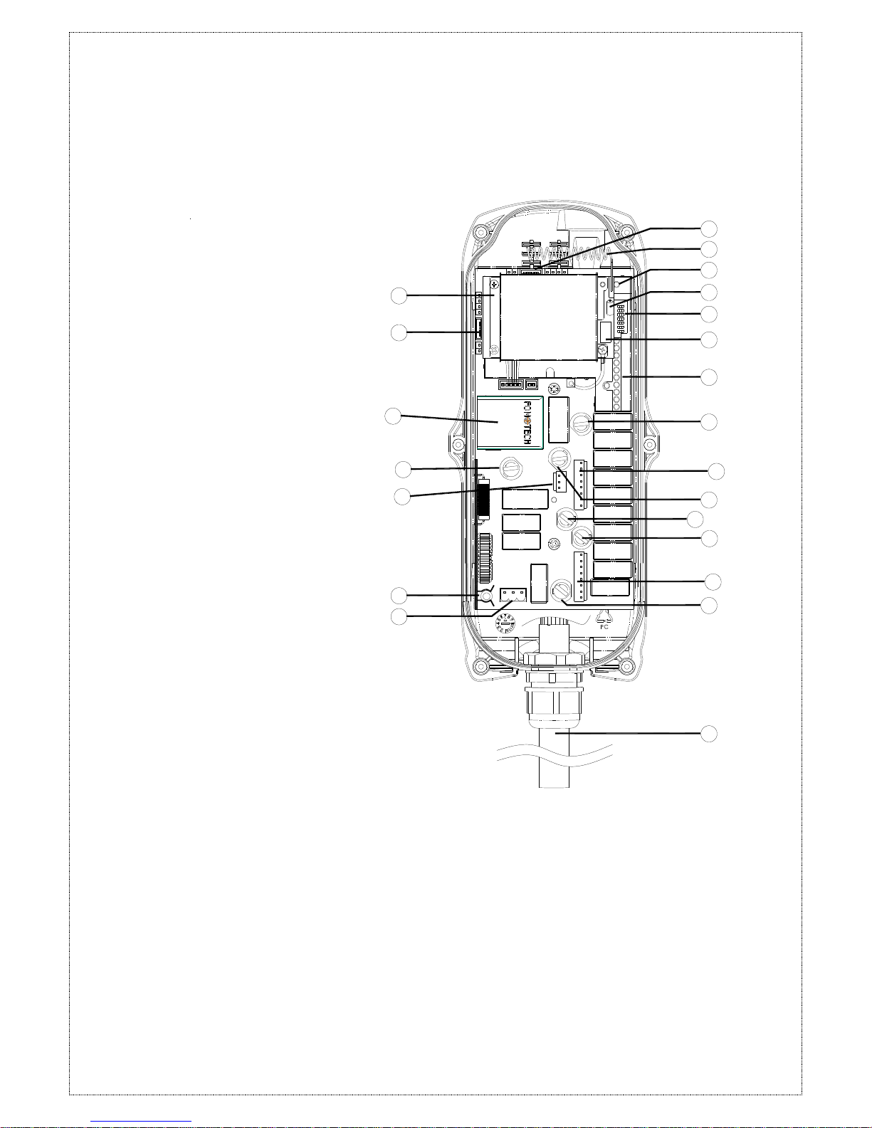
44..11..33 AAllpphhaa 660088 IInntteerrnnaall AAsssseemmbblly
y
(Fig. 8) Internal Parts Assembly
1) Receiving RF module
2) External programming port(CN5)****
3) Power module
4) Secondary power AC fuse (F1)**
5) Contact output seat (CN8)
6) Primary power AC fuse (FF1) **
7) AC power input seat (CN2)
8) External programming port(CN9)****
9) Internal Antenna
10) System Status LED display***
11) External antenna port
12) ID code dip-switch
13) RF channel dip-switch
14) Contact relay LED display
15) Pushbutton #1and #2 fuse (5.0A)
16) Contact output seat (CN3)
17) MAIN contact fuse (5.0A)
18) Pushbutton #3 and #4 fuse (5.0A)
19) Pushbutton #5 and #6 fuse (5.0A)
20) Contact output seat (CN4)
21) LV & AUX fuse (5.0A)
22) Cable gland & output cable
* Power module: Including transformer or
full-voltage module.
** Please refer to 4.3 α604/α608/α612
Receiver Power Fuse List on Page 12.
*** Please refer to page 40 for system status
LED display information.
**** For item 2 & 8, the receiver and country
code / ID have to be set at the same time.
- 11 -
1
2
3
4
44..22 AAllpphhaa 661122
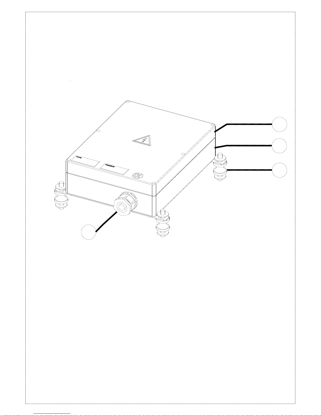
44..22..11 AAllpphhaa 661122 MMooddeellss EExxtteerrnnaall AAsssseemmbblly
y
SIZE:300mm X 230mm X 86mm
(Fig. 9) External Parts Assembly
1) Transparent top cover 3) Mounting bracket with shock absorbers
2) Light-gray colored base 4) Cable gland / Cord grip

- 12 -
18
21
20
19
17
15
5
11
12
10
8
9
7
1
3
4
2
16
13
6
14
44..22..22 AAllpphhaa 661122 MMooddeellss IInntteerrnnaall AAsssseemmbblly
y
(Fig. 10) Internal Parts Assembly
1) Power LED display* 14) Receiving antenna (see below 4.3)
2) SQ LED display** 15) Third power fuse FF2
3) Status LED display**** 16) Receiving RF module
4) Relay power LED display 17) External antenna port
5) Programming port (CN3)***** 18) RF channel dip-switch
6) Programming port (CN5)***** 19) ID code dip-switch
7) Short pin 20) Secondary power fuse (see below 4.3)
8) Function dip-switch 21) Voltage selector seat CN10
9) Pushbutton #3 and #4 relay fuse F3 (5.0A) 22) MAIN relay fuse F6 (5.0A)
10) Pushbutton #5 and #6 relay fuse F3 (5.0A) 23) Pushbutton A4 relay fuse F8 (5.0A)
11) Pushbutton A1and A2 relay fuse F5 (5.0A) 24) Primary power fuse (see below 4.3)
12) Pushbutton A3 relay fuse F7 (5.0A) 25) Power port CN2
13) Pushbutton #1 and #2 relay fuse F2 (5.0A) 26) Low-voltage (LV) relay fuse F9 (5.0A)
* POWER ~ AC Power Source Indicator "on" → AC input power supplied.
"off" → No AC input power.
** SQ ~ RF Signal Indicator "on" → RF signal detected and received.
"off" → No RF signal detected or received.
Blinking at transmitter power “off” → Other radio interference.
*** RELAY_COM ~ DC Power Source to Relays "on" → DC power to relays.
"off" → No DC power to relays.
**** STATUS ~ Receiver System Status LED Display → Please refer to page 40.
***** Programming port ~ Item 5 & 6, the receiver and country code / ID have to be set at the same time.

- 13 -
44..33 AAllpphhaa 660044//660088//661122 RReecceeiivveerr PPoowweerr FFuussee LLiisstt
Type
Parts No.
Voltage
DC12V~24V
AC24
AC36~48V
AC100~120
V
AC220~240
V
AC380~440
V
AC100~240V
Full-Voltage
α604
α607
α608
FF1
3A
1A
2A
F1
3A
2A
0.5A
1A
α612
FF2
2A
2A
FF1
3A
1A
F1
3A
2A
0.8A
- 14 -
STOPPOWER
U
D
W
E
FOM TECH
EN ISO 13849-1:2008, PLd
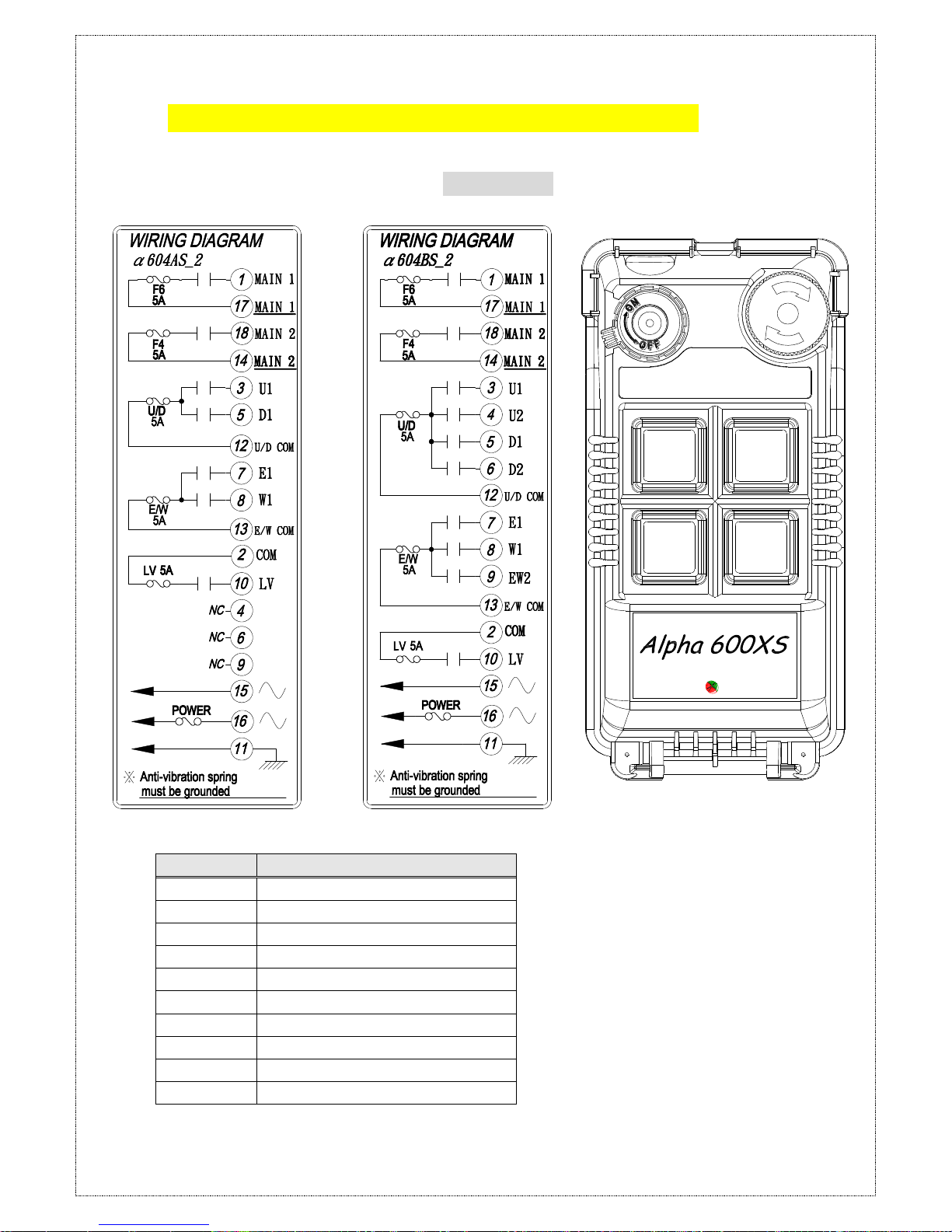
55.. OOUUTTPPUUTT CCOONNTTAACCTT DDIIAAGGRRAAMMSS
55..1
1
AAllpphhaa 660044 MMooddeellss MMAAIINN RReellaayy DDuuaall OOuuttppuut
t
Relay
Description
MAIN 1
MAIN relay 1
MAIN 2
MAIN relay 2
U1
‘U’ 1-speed
U2
‘U’ 2-speed
D1
‘D’ 1-speed
D2
‘D’ 2-speed
E1
‘E’ 1-speed
W1
‘W’ 1-speed
EW2
‘E’ & ‘W’ 2-spped
LV
Transmitter low voltage
 Loading...