

Fomotech ALPHA600SERIES User Manual

1.
SSAAFFEETTYY IINNSSTTRRUUCCTTIIOON
The Alpha 608 is relatively simple to use, however, it is very important to observe the proper safety
procedures before, during, and after operation. When used properly, the Alpha 608 will enhance
safety, productivity and efficiency in the workplace.
The following procedures should be strictly followed:
1. Do not change the IDs on transmitter encoder and receiver decoder boards at will.
2. Check the transmitter casing and pushbuttons daily. Should any damage that could inhibit the
proper operation of the transmitter be found the unit should be immediately removed from
service.
3. Check the transmitter voltage whenever it is operated.
4. The red emergency stop button (EMS) should be checked at the beginning of each shift to
ensure it is in proper working order and the “Stop” command is being received by the receiver.
5. In the event of an emergency press down the EMS button will immediately deactivates the
receiver MAIN relay and the transmitter power. Then turned the power “off ” from the main
power source to the crane or equipment.
6. Do not use the same RF channel and ID code as any other system in use at the same facility or
within 300-meter distance.
7. Ensure the waist belt is worn at all time during operation to avoid accidental damage to the
transmitter.
N
8. Never operate a crane or equipment with two transmitters at the same time with the same RF
channel and ID code, as it will cause radio interference.
FCC 15.21: “Changes or modifications are not expressly approved by the manufacturer could
void the user’s authority to operate the equipment.”
“Operations is subject to the following two conditions: (1) this device may cause interference,
and (2) this device must accept any interference, including interference that may cause
undesired operation of the device.”
- 1 -
2.
PPUUSSHHBBUUTTTTOONN CCOONNFFIIGGUURRAATTIIOONN
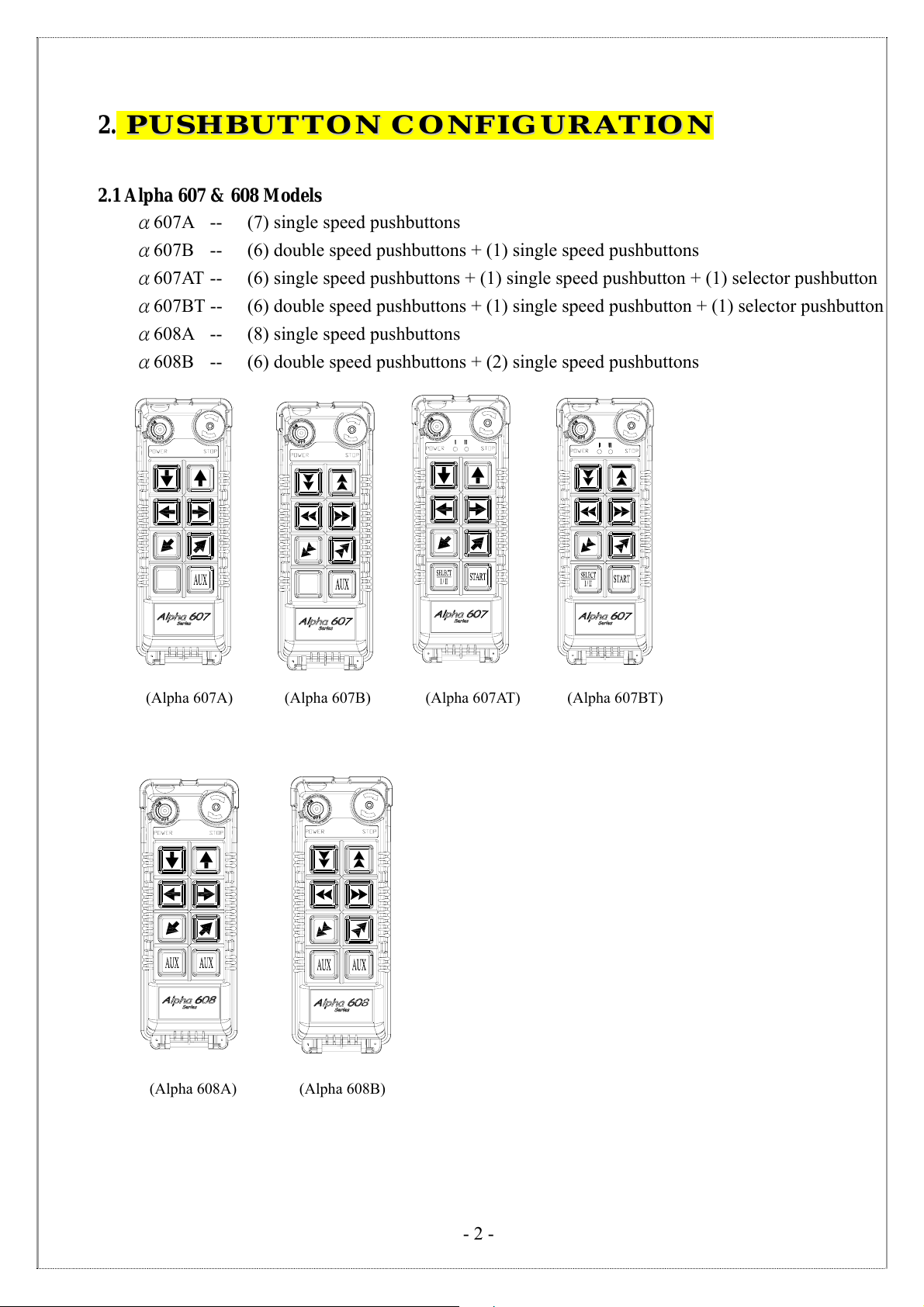
2.1 Alpha 607 & 608 Models
α607A -- (7) single speed pushbuttons
α607B -- (6) double speed pushbuttons + (1) single speed pushbuttons
α607AT -- (6) single speed pushbuttons + (1) single speed pushbutton + (1) selector pushbutton
α607BT -- (6) double speed pushbuttons + (1) single speed pushbutton + (1) selector pushbutton
α608A -- (8) single speed pushbuttons
α608B -- (6) double speed pushbuttons + (2) single speed pushbuttons
(Alpha 607A) (Alpha 607B) (Alpha 607AT) (Alpha 607BT)
(Alpha 608A) (Alpha 608B)
- 2 -
33.. TTRRAANNSSMMIITTTTEERR OOUUTTLLIINNEE
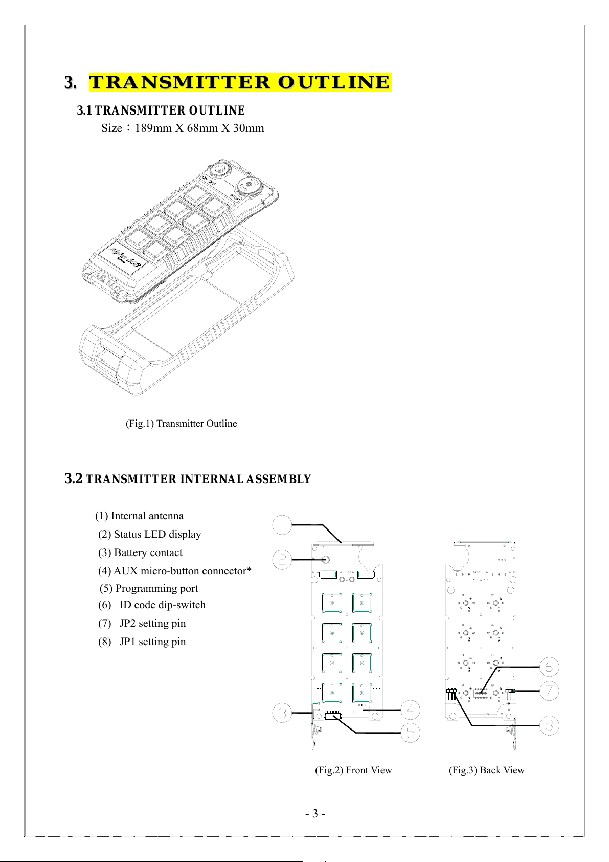
3.1 TRANSMITTER OUTLINE
Size:189mm X 68mm X 30mm
(Fig.1) Transmitter Outline
TRANSMITTER INTERNAL ASSEMBLY
3.2
(1) Internal antenna
(2) Status LED display
(3) Battery contact
(4) AUX micro-button connector*
(5) Programming port
(6) ID code dip-switch
(7) JP2 setting pin
(8) JP1 setting pin
(Fig.2) Front View (Fig.3) Back View
- 3 -
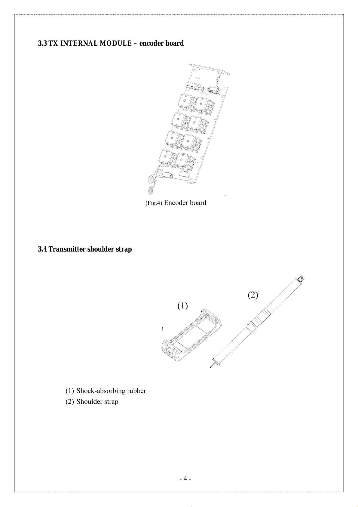
3.3 TX INTERNAL MODULE – encoder board
3.4 Transmitter shoulder strap
(Fig.4) Encoder board
(1)
(2)
(1) Shock-absorbing rubber
(2) Shoulder strap
- 4 -
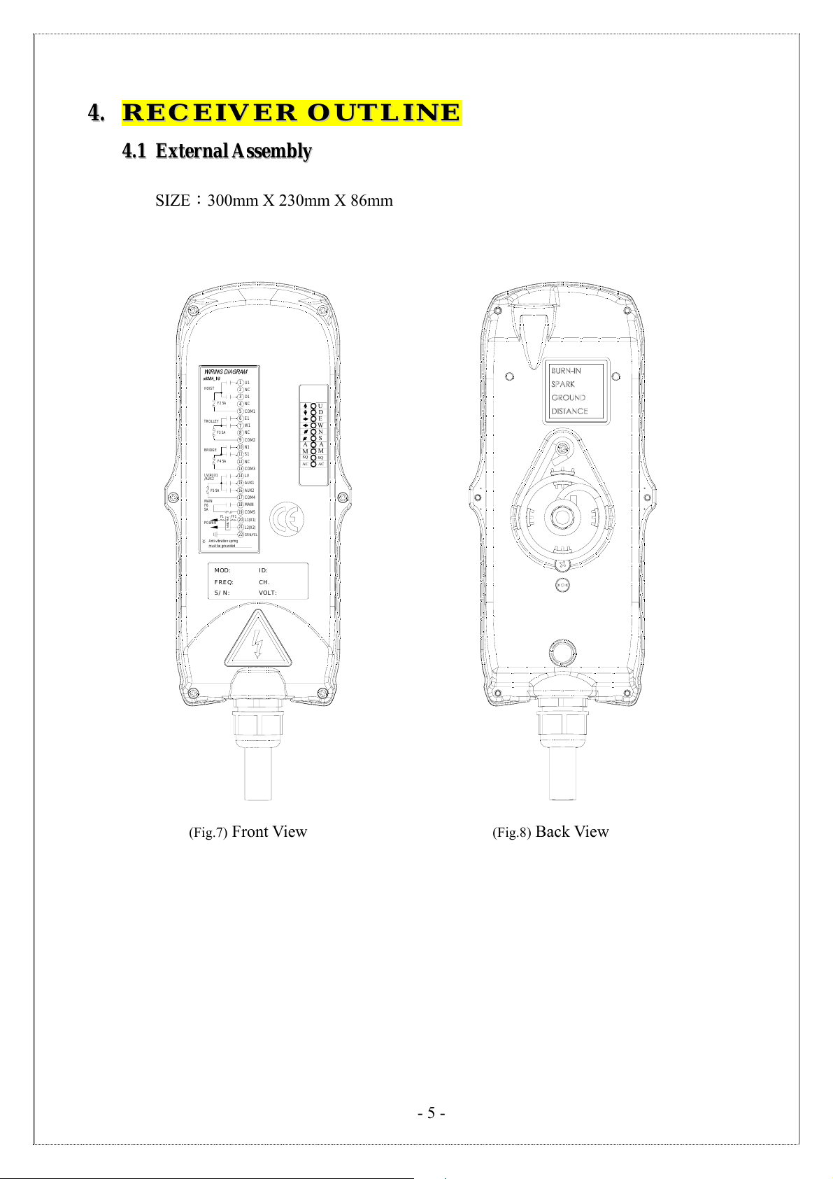
44.. RREECCEEIIVVEERR OOUUTTLLIINNEE
44..11 EExxtteerrnnaall AAsssseemmbbllyy
SIZE:300mm X 230mm X 86mm
HOIST
F2 5A
TROLLEY
F3 5A
BRIDGE
F4 5A
LV/AUX1
/AUX2
F5 5A
MAIN
F6
5A
FILTER
F1
FF1
POWER
Anti-vibration spring
must be grounded
U1
1
NC
2
D1
3
NC
4
COM1
5
E1
6
W1
7
NC
8
COM2
9
10
N1
11
S1
NC
12
COM3
13
14 LV
AUX1
15
AUX2
16
COM417
18
MAIN
19
COM5
L1(X1)
20
21
L2(X2)
22
GRN/YEL
U
D
E
W
N
S
A
A
M
M
SQ
SQ
AC
AC
MOD:
FREQ:
S/ N:
ID:
CH.
VOLT:
(Fig.7) Front View (Fig.8) Back View
- 5 -

44..22 IInntteerrnnaall AAsssseemmbblly
y
1) Receiving RF module
2) External programming port
3) Secondary power AC fuse (0.50A)
4) Contact output seat (CN8)
5) Primary power AC fuse (1.0A)
6) AC power input seat (CN2)
7) Internal Antenna
8) System Status LED display*
9) External antenna port
10) ID code dip-switch
11) RF channel dip-switch
12) Contact relay LED display
13) Pushbutton #1and #2 fuse (5.0A)
14) Contact output seat (CN3)
15) MAIN contact fuse (5.0A)
16) Pushbutton #3 and #4 fuse (5.0A)
17) Pushbutton #5 and #6 fuse (5.0A)
18) Contact output seat (CN4)
19) LV & AUX fuse (5.0A)
20) Cable gland & output cable
* Please refer to page 27 for system status
LED display information.
1
2
3
4
5
6
(Fig. 9) Internal Parts Assembly
F
U
S
E
E
S
U
F
F
U
S
E
F
U
S
E
F
U
S
E
E
S
U
F
7
8
9
10
11
12
13
14
15
16
17
18
19
20
- 6 -

55.. OOUUTTPPUUTT CCOONNTTAACCTT DDIIAAGGRRAAMMSS
U1
NC
D1
NC
COM1
E1
W1
NC
COM2
N1
S1
NC
COM3
LV
AUX1
NC
COM4
MAIN
COM5
L1(X1)
L2(X2)
GRN/YEL
U1
1
U2
HOIST
F2 5A
TROLLEY
F3 5A
BRIDGE
F4 5A
LV/AUX1
F5 5A
MAIN
F6
5A
F1
POWER
Anti-vibration spring
must be grounded
2
D1
3
D2
4
COM1
5
E1
6
W1
7
E/W2
8
COM2
9
10
N1
11
S1
12
N/S2
13
COM3
14
LV
15
AUX1
16
NC
17
COM4
18
MAIN
19
20
21
22
COM5
L1(X1)
L2(X2)
GRN/YEL
FILTER
FF1
55..11 AAllpphhaa 660077 MMooddeellss
Alpha 607A Alpha 607B
HOIST
F2 5A
TROLLEY
F3 5A
BRIDGE
F4 5A
LV/AUX1
F5 5A
MAIN
F6
5A
FILTER
F1
FF1
POWER
Anti-vibration spring
must be grounded
1
2
3
4
5
6
7
8
9
10
11
12
13
14
15
16
17
18
19
20
21
22
- 7 -
 Loading...