

Page 1

1
TTAABBLLEE OOFF CCOONNTTEENNTTSS
Page
1. INTRODUCTION ................................................................................................. 3
2. SAFETY INSTRUCTIONS ................................................................................... 5
3. SYSTEM DESCRIPTIONS .................................................................................. 6
3.1 TRANSMITTER OUTLINE
3.1.1 TRANSMITTER EXTERNAL DESCRIPTIONS................................... 6
3.1.2 TRANSMITTER INTERNAL DESCRIPTIONS.................................... 7
3.1.3 RECHARGEABLE BATTERY, BATTERY CHARGER AND
SHOULDER BELT VIEWS ..................................................................... 7
3.2 RECEIVER OUTLINE
3.2.1 RECEIVER EXTERNAL DESCRIPTIONS ............................................ 8
3.2.2 RECEIVER INTERNAL DESCRIPTIONS .............................................. 8
3.2.3 RECEIVER MOUNTING DIMENSION................................................... 9
3.2.4 CARDS INSIDE RECEIVER .................................................................... 9
4. SYSTEM FUNCTIONS
4.1 TRANSMITTER JOYSTICK DESCRIPTIONS ............................................ 13
4.2 JOYSTICK CONFIGURATIONS AND SETTINGS .................................... 24
4.3 TRANSMITTER PUSHBUTTON DESCRIPTIONS .................................... 25
4.3.1 PUSHBUTTON TYPES .......................................................................... 25
4.3.2 FUNCTION SETTINGS .......................................................................... 27
4.3.2.1 TRANSMITTER FUNCTION SETTINGS................................. 28
4.3.2.2 RECEIVER FUNCTION SETTINGS.......................................... 30
4.4 SPECIAL TYPES .............................................................................................. 34
4.5 CUSTOMIZED TYPES..................................................................................... 36
4.6 FREQUENCY TABLE................. ...................................................................... 37
5. SYSTEM SETTINGS
5.1 TRANSMIITTER LCD FUNCTION SETTINGS............................................. 39
5.2 LCD DISPLAY DESCRIPTIONS...................................................................... 39
6. RECEIVER STATUS LIGHT AND INSTALLATION
6.1 RECEIVER STATUS LIGHT............................................................................. 44
6.2 RECEIVER LED STATUS................................................................................. 44
6.3 PREPARATION..... ............................................................................................. 46
6.4 STEPS-BY-STEPS INSTALLATION................................................................. 46
6.5 WIRING DIAGRAM ......................................................................................... 47
6.6 SYSTEM TESTING............................................................................................ 47
Page 2

2
7. TRANSMITTER OPERATING INSTRUCTION
7.1 POWER “ON” THE SYSTEM ......................................................................... 47
7.2 TRANSMITTER SYSTEM STATUS DISPLAY ............................................... 48
7.2.1 TRANSMITTER LED DISPLAY ............................................................. 48
7.2.2 TRANSMITTER LED STATUS TABLE .................................................. 48
7.3 JOYSTICK CORRECTION
7.3.1 REASONS FOR JOYSTICK CORRECTION........................................... 49
7.3.2 ENTER JOYSTICK CORRECTION MODE............................................ 49
7.3.3 JOYSTICK CORRECTION STEPS.......................................................... 50
7.3.4 EXIT .......................................................................................................... 50
7.3.5 FUNCTION CHANGE SETTINGS.......................................................... 51
8. BATTERY CHARGING ............................................................................................ 53
9. TROUBLE SHOOTING ............................................................................................. 54
10. SYSTEM SPECIFICATION .................................................................................. 55
11. PARTS LIST .............................................................................................................. 57
Page 3

3
1. INTRODUCTION
The Alpha 6000 is a highly sophisticated industrial radio remote control system. The versatile
features of Alpha 6000 permits its usage in a wide range of industrial applications. The system can
be used to control all types of industrial cranes, tower cranes, building construction equipment,
automatic control systems, mining equipment, and many others.
The Alpha 6000 incorporates numerous advanced safety features and software programming that will
ensure maximum security and safety in the workplace. The major features of Alpha 6000 industrial
radio remote control system are as follow:
* The system is equipped with highly evolved software that has redundant error checking and
correcting capabilities to ensure 100% error-free transmission, decoding, and control of all
output relays. This highly evolved software includes CRC (Cyclical Redundancy Check) and
Hamming Codes (Error Recovery) programming. The responding time from system error to
receiver auto-shutdown is maximum 1 second.
* The encoding system utilizes advanced microprocessor control for 100% error-free data
transmission. The availability of 65,536 sets of unique security ID codes + 68 distinct RF
channels will ensure that only commands from a matching control transmitter can be carried out
without any interference from other radio systems.
* The decoding system utilizes dual-microprocessor control, which will ensure 100% error-free
calculating, bit checking and correcting of all incoming data.
* The system also utilizes an additional central microprocessor for data comparison and
crosschecking between the two decoding microprocessors. When faults are detected via this
central microprocessor, for maximum safety, the entire system will be shutdown immediately to
avoid possibility of any accidents occurring.
* The system utilizes PLL synthesized RF transmission. It allows the user to select from 68 sets
of frequency channels best suited for the environment. The frequency channel for transmitter
and receiver is selected via programming software. The receiver also has the ability to
auto-scan from these 68 sets of frequency channels. The receiver will search and locked on to
the intended matching control transmitter.
* For added safety the receiver also utilizes dual Safety Relays for the receiver MAIN relay
circuit. If the receiver MAIN relay is defective (example: fails to open or close during operation
or not respond to a “Stop” command) a fault will be detected and the system will be shut down
immediately to avoid possibility of any accidents occurring.
* The Alpha 6000 is equipped with numerous self-diagnosing functions, which include
transmitter low-voltage detection/warning, faulty pushbutton/joystick detection, faulty safety
MAIN relays detection, faulty relay boards detection, faulty EEPROM detection, faulty RX
module detection, incorrect ID code detection, and receiver MAIN auto-deactivation when
transmitter low-voltage is detected, when encountering strong radio interference, and when the
transmitter/operator is out of receiving range.
* The transmitter is equipped with power auto shutdown function: After 5 minutes of inactivity,
that is 5 minutes after the last pushbutton is released, the transmitter power will shut off
Page 4

4
automatically. (0-120 minutes or no auto shutdown is selectable)
* The transmitter casing is composed of special engineering plastic and pushbutton waterproof
layer. The engineering plastic is featured with wearable, oil-proof, acid-proof, alkaline-proof,
high temperature resistance, anti-UV, water-proof and dust-proof. With the self-developed no
contact cross type and single axis joystick, there is no disadvantage of friction and
non-durability as the operation of direct contact. The operation life and reliability is for a
minimum of 1 million operating cycles.
* The receiver enclosure is composed of 100% aluminum alloy. It may eliminate the static
completely and avoid interference from radio radiation.
* Relay and proportional joystick output via RS485 interface (optional). It is also applicable
on internet type control.
* Receiver internal circuit is completely modularized. Including: receiving RF module,
decoding module, relay module, proportional output module, LCD display module and power
module. It is easy for the users to replace and extend.
* LCD display module shows the current receiver status, including individual relay output,
proportional output, receiving signal strength, error messages...etc.
* Maximum number of joysticks and pushbuttons on each transmitter:
1. 2 double axes joysticks plus 16 single speed pushbuttons
2. 8 single axis joysticks plus 12 single speed pushbuttons
3. If there is no joystick on the transmitter, maximum 32 single speed pushbuttons can
be installed on each transmitter.
* Relay and proportional output:
1. Maximum 32 relays. 8pcs relays on each relay interface card, maximum 4 relay
interface cards.
2. Proportional output interface cards available:
Standard: By voltage/current: 0~+5V, 0~+10V, 0~±5V, 0~±10V, 4~20mA, 0~20mA & 0~24mA
Customized: Customized proportional output interface card (optional).
* All Alpha 6000 function setting and selection can be done via Alpha 6000 software.
Page 5

5
2. SAFETY INSTRUCTIONS
The Alpha 6000 system is relatively simple to use. However, it is very important to observe the
proper safety procedures before, during, and after operation. When using properly the Alpha 6000
systems will enhance productivity and efficiency in the workplace.
The following instructions should be strictly followed:
1. Make a daily check of the transmitter casing, joysticks and pushbuttons. Should it appear that
anything could inhibit the proper operation of the transmitter unit, it should be immediately
removed from service.
2. The transmitter voltage should be checked on a daily basis. If the voltage is low, the battery
pack should be recharged or replaced (refer to page 45 for battery power status LED display).
3. The emergency stop button (EMS) should be checked at the beginning of each shift to ensure
they are in the proper working order.
4. In the event of an emergency, activate the emergency stop button immediately by pressing the
red EMS button down. This will immediately disconnect the transmitter power and receiver
MAIN relays. Then turn the power “off” from the main power source of the equipment.
5. The transmitter power key, which is located on the right side of the transmitter box, should be
turned “off” after each use and should never leave the power key in “on” position when the unit
is unattended.
6. Do not use the same frequency channel and ID code as any other unit in use at the same facility
or within distance of 300 meters to avoid interference.
7. Ensure the waist belt and the shoulder strap is worn at all time during operation to avoid
accidental damages to the transmitter box.
8. Never operate a crane or equipment with two (2) transmitter units at the same time with same
frequency channel and ID code.
Page 6
6
MODEL
VOLTAGE
BAND
POWER
S/NO.
0
1
2
3
4
5
6
7
8
9
A
CHANNEL A B C
BC
:
:
:
:
:
:
V
m
MHz
RXWTX W
3. SYSTEM DESCRIPTIONS
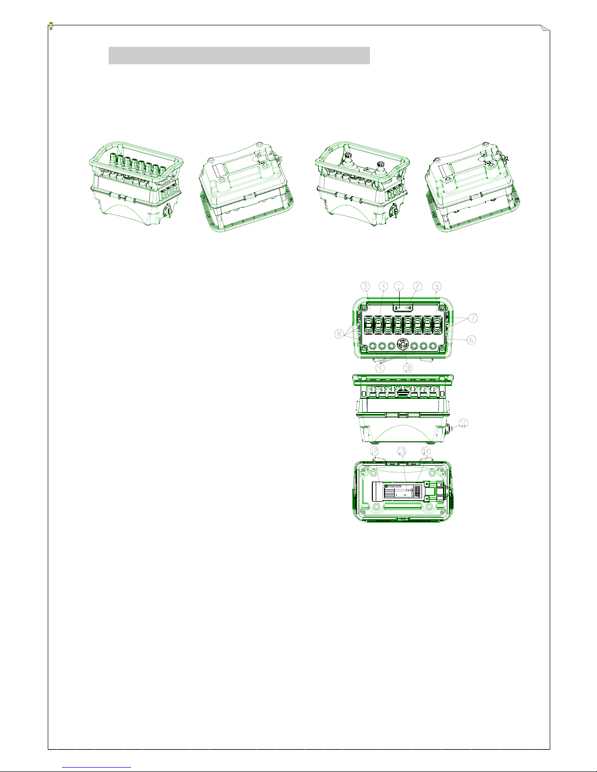
3.1 Transmitter Outline
3.1.1Transmitter External Descriptions
268mm × 162mm × 178.5mm
(Fig. 1) Transmitter Top & Bottom View
1. Battery Power LED Display
2. Status LED Display
3. Information Top Plate (engraved)
4. Joystick Rubber Boot
5. Joystick Rubber Boot
6. START Pushbutton
7. AUX/RES Pushbutton (side panel)
8. AUX/RES Pushbutton (side panel)
9. AUX/RES Pushbutton (top panel)
10 Emergency Stop Button (EMS)
11. Power Key (detachable)
12. Battery Contact (gold-plated)
13. System Information
14. Battery Slot
(Fig. 2) Transmitter Exterior Views
Page 7
7
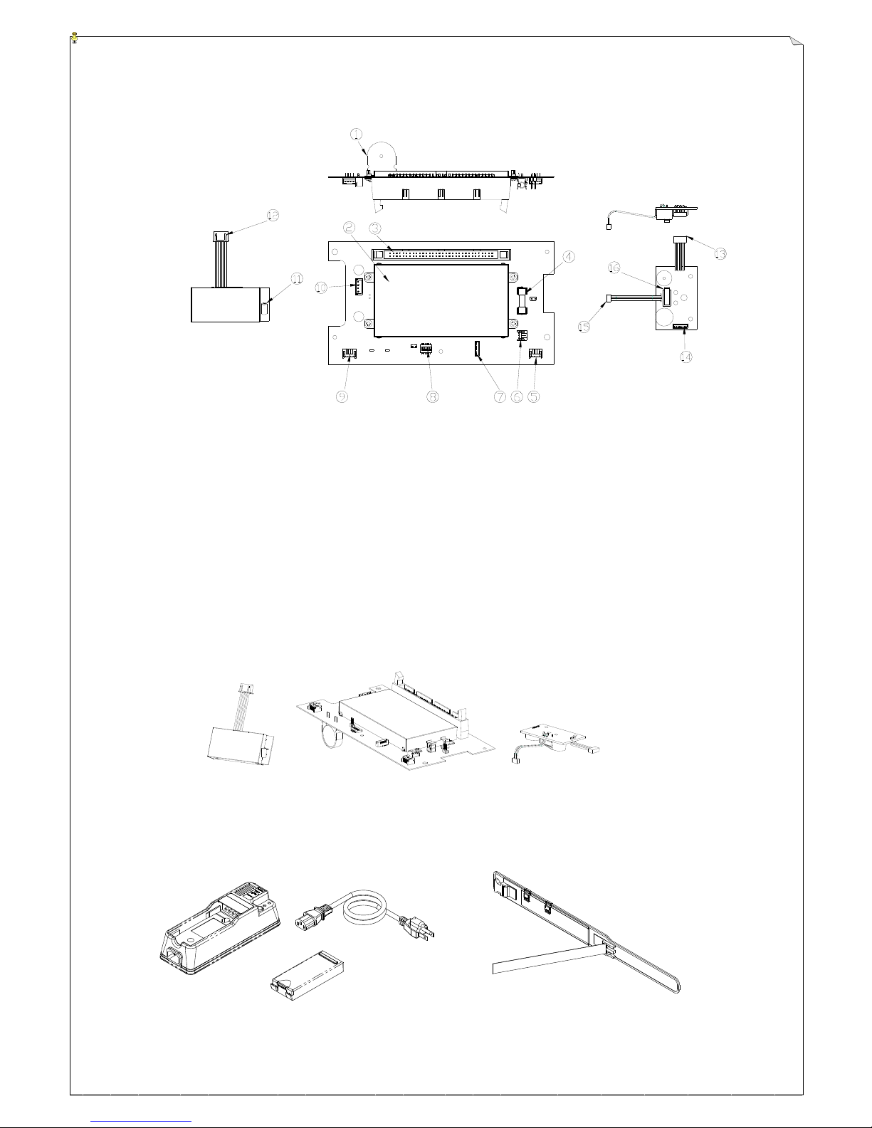
3.1.2 Transmitter Internal Descriptions
(Fig. 3) RF Module, Encoder Board and Power Switch Views
1. Buzzer
9. TX Module Connector Dip-Switch
2. Encoder Anti-Magnetic Shielding Plate
10. Power Input Connector Port
3. Ribbon Type Connector Port
11. Antenna Port
4. Power Fuse (0.5A)
12. TX module Connector
5. A/G Sensor Ribbon Type Connector Port
13. A/G Sensor Ribbon Type Connector
6. Power Key Switch Connector Port
14. External Programming Port
7. External Programming Port
15. Power Key Switch Ribbon Type Connector
8. Function Setting Dip-Switch (incl. joystick
correction)
16. Power Key Switch
2
(Fig. 4) Encoder Board, TX Module and A/G Sensor Views
3.1.3 Rechargeable Battery, Battery Charger and Shoulder Belt Views
(Fig. 5) Rechargeable battery、Battery Charger、Shoulder Belt Views
A/G Sensor Board
TX Module
Encoder Board
Page 8
8
5
RECEIVER OUTLINE
3.2 Receiver Outline
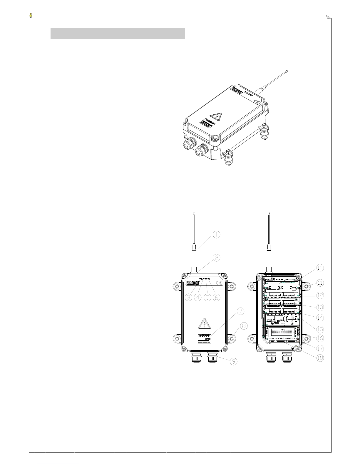
3.2.1 Receiver External Descriptions
300mm×171mm×115mm
(excluding antenna and plug-in connector)
(Fig. 6) Receiver External Descriptions
3.2.2 Receiver Internal Descriptions
1. Antenna
2. Antenna Port
3. AC Power Display
4. SQ Status Display
5. Status Display
6. Main Relay Display
7. System Information Plate
8. Shock Absorber*4
9. Cable Gland*2
10. RX Module Card
11. Output relay Card I
12. Output relay Card II
13. Output relay Card III
14. Output relay Card IV
15. Decoder Module Card
16. LCD Display
17. Proportional Output Module Card
18. Power Module Card
(Fig. 7) Receiver External/Internal Descriptions
Page 9

9
LCD Display Card
100~240VAC Power Module
3.2.3 Receiver Mounting Dimension
(圖八) 防震座尺寸座標
3.2.4 Cards inside Receiver
RX Module Card Decoder Card Relay Module Card
(Fig. 8) Cards inside Receiver
Page 10
10
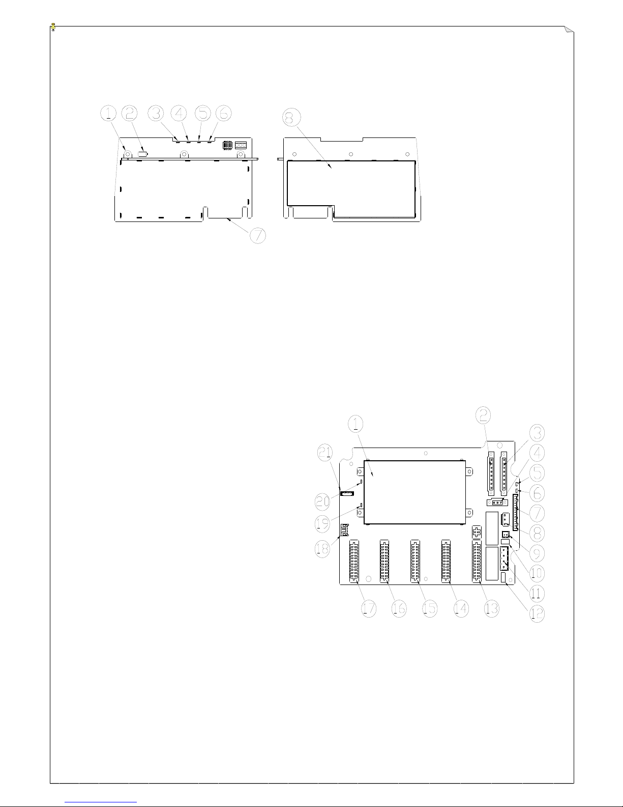
(1) RX Module Card
(Fig. 9) RX Module Card
1. RX Module Card Release Clip
6. Receiver Power LED Display
2. RX-1 Antenna Port
3 Receiver MAIN Relay LED Display
7. RX Module Golden Finger Slot
4. Receiver Status LED Display
5. Receiver SQ Status LED Display
(2) Decoder Card
1. Decoder Card Anti-magnetic Shielding Plate
2. SICK LASER Input Contact CN13
3. SICK LASER Input Contact CN14
4. SICK LASER Contact Power
5. Relay Power(COM) LED Display
6. MAIN Relay Status LED Display
7. “Proportional Output Module” Connecting Port
8. DC12V Power Input
9. Spare DC12V Power Output
10. MAIN Relay 1 Fuse F3 250V/5A
11. MAIN Relay Contact
12. MAIN Relay 2 Fuse F5 250V/5A
13. Relay Module Card Golden Finger Slot IV(K25~K32)
14. Relay Module Card Golden Finger Slot III(K17~K24)
15. Relay Module Card Golden Finger Slot II(K09~K16)
16. Relay Module Card Golden Finger Slot I (K01~K08)
17. RX Module Golden Finger Slot
18. External Extension Contact
19. Decoder Card Power LED Display
20. Status LED Display
21. Programming Port
(Fig. 10) Decoder Card
8. RX Module Anti-Magnetic
Page 11
11
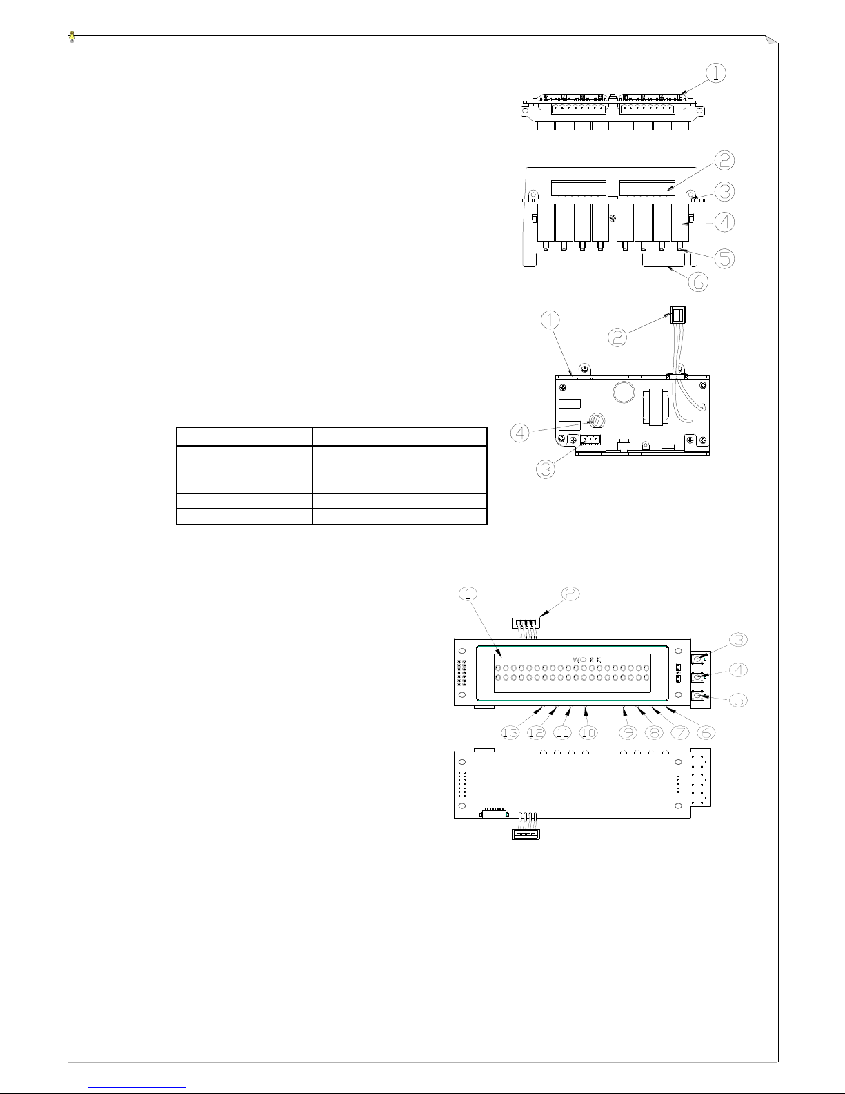
(3) Relay Card
1. Relay LED Display Pole
2. Relay Output Contact Connector Port
3. Relay Fixing Frame
4. Relay
5. Relay LED Display
6. Relay Card Golden Finger Slot
(Fig. 11) Relay Card
(4) Power Supply Module
1. Aluminum Base for Power Supply Card
2. Power DC12V/2A Output Connector
3. Power Input Connector
4. Fuse Holder
5. Input Fuse: 3A (100-240VAC)
5A (48VAC)
Power supply module
Fuse
AC100~240V
3A fast acting glass tube fuse
AC380~460V
3A tube fuse (with
terminal/fast acting type)
AC28~48V
5A fast acting glass tube fuse
DC12~24V
5A fast acting glass tube fuse
(5) LCD Display
1. LCD Screen
2. Input / Output connecting Port
3. Pushbutton 1
4. Pushbutton 2
5. Pushbutton 3
6. Joystick 8/VR8 Output Status LED
7. Joystick 7/VR7 Output Status LED
8. Joystick 6/VR6 Output Status LED
9. Joystick 5/VR5 Output Status LED
10. Joystick 4/VR4 Output Status LED
11. Joystick 3/VR3 Output Status LED
12. Joystick 2/VR2 Output Status LED
13. Joystick 1/VR1 Output Status LED
Joystick 1/VR1 ~ joystick 8/VR8 output status LED: Each joystick/VR is equipped with one red/green dual
color output status LED. Both red and green status LED will not ON when there is no output from joystick.
When the joystick output does not reach to the highest point, green status LED blinks. The lower the joystick
output, the slower the green LED blinks. The higher the joystick output, the faster the green LED blinks.
When the output reaches to the highest point, green LED OFF and red LED steady ON.
(Fig. 13) LCD Display
(Fig. 12) Power Supply Module
Page 12
12
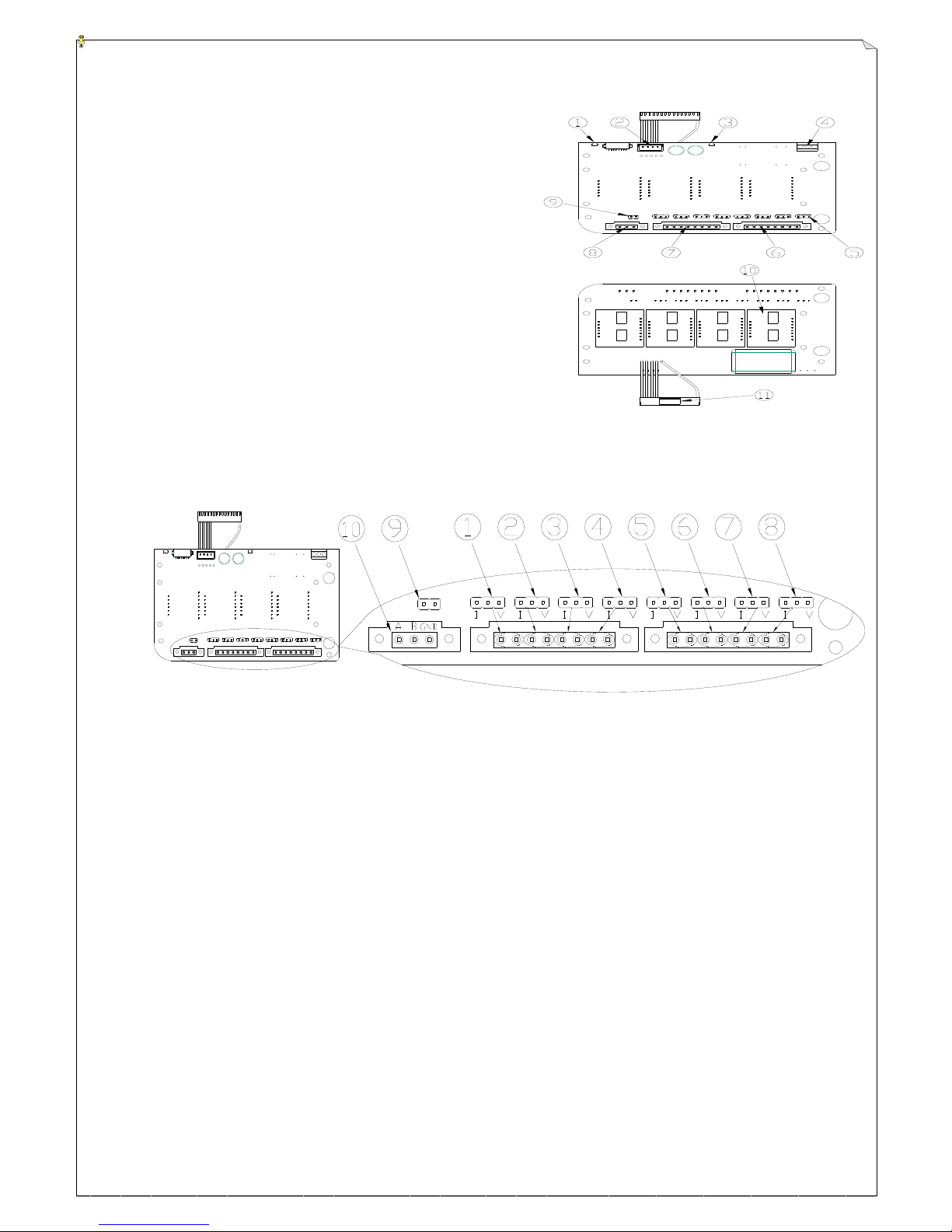
(Fig. 14) Voltage/current proportional
output module
(6) Voltage/Current Proportional Output Module
1. Status LED
2. ” LCD Display” Connector
3. RESET Status LED
4. External Power Input
5. Joystick/VR Output Voltage & Current Setting JUMPER
6. Joystick 5/VR5 ~ Joystick 8/VR8 Voltage & Current Output
7. Joystick 1/VR1 ~ Joystick 4/VR4 Voltage & Current output
8. RS485 Output Interface (optional)
9. RS485 Terminal Resistance Setting JUMPER
10.Proportional Output Module Card
11.Output Module to Decoder Card Connecting Port
① ~ ⑧ Corresponding joystick 1/VR1 ~ joystick 8/VR8
* Plug short pin into the 3-pin JUMPER left (“I” mark): Select “current” output and plug short pin into the 3-pin
JUMPER right (“V” mark): Select “voltage” output。
Current output: Software setting(0~20mA、0~24mA & 4~20mA available) and plug the short pin into the 3-pin
JUMPER left.(“I” mark)
Voltage output: Software setting (0~+5V、0~+10V、0~±5V & 0~±10V available) and plug the short pin into
the 3-pin JUMPER right.(“V” mark)
* Each joystick/VR corresponds to the 2-pin output terminal. Left terminal is for voltage/current output and right
terminal is for GND.
⑨ RS485 output terminal with 150Ω resistance. Plug in short pin: Use terminal resistance; not using short pin: Not
using terminal resistance.
⑩ RS485 output
Page 13

13
4. SYSTEM FUNCTIONS
4.1 Transmitter Joystick Descriptions
Joystick types can be customized by the demand per different customer. The available ones are
described as below:
JOYSTICK
TYPE
DESCRIPTION
Proportional
joystick
Double axes joystick
Neutral angle range 0°±5°, max. motion angle ±40°
Joystick Up/Left axis +6°~+40° for 0~+MAX proportional output. (127 steps
resolution)
Joystick Down/Right axis -6°~-40° for 0~+MAX or 0~-MAX proportional output.
(127 steps resolution)
Single axis joystick
Neutral angle range 0°±3°, max. motion angle ±35°
Joystick Up axis +4°~+35° for 0~+MAX proportional output. (127 steps resolution)
Joystick Down axis -4°~-35° for 0~+MAX or 0~-MAX proportional output. (127
steps resolution)
* Move joystick to any angle and release, joystick will auto return to neutral position.
* Back to zero checking after transmitter joystick startup.
Single-side type
VR(#)
* 0° on the start position of the rotary switch left.
Rotating clock-wisely 0°~240° for 0~+MAX proportional output (255 steps
resolution)
* Rotate switch to any angle and release, rotary switch will remain at that angle and
will not auto return to 0°.
* Pre-set transmitter startup as not having back to zero check.
* Proportional output available:
Interface card with voltage/current proportional output: 0~+5V / 0~+10V /
4~20mA / 0~20mA / 0~24mA
(not-selectable: 0~±5VDC / 0~±10VDC)
Page 14
14
Neutral type VR
* 0° as the rotating central position. Clockwise 0°~+120°, counterclockwise 0°~-120°.
* 0°~+120°, rotating range for 0~+MAX proportional output. (127 steps resolution)
* 0°~-120°, rotating range for 0~+MAX or 0~-MAX proportional output. (127 steps
resolution)
* Rotate switch to any angle and release, rotary switch will remain at that angle and
will not auto return to 0°.
* Pre-set transmitter startup as not having back to zero check.
* Proportional output available:
By voltage/current: 0~+5V, 0~+10V, 0~±5V, 0~±10V,4~20mA,0~20mA & 0~24mA.
* To use output not within 0~±5VDC / 0~±10VDC, axis relay 2pcs is needed.
1. When VR is at 0°, 2 axis relays are OFF.
2. When VR is at 0°, rotate it clockwise. Upper axis relay is ON; Lower axis
relay is OFF.
3. When VR is at 0°, rotate it counter-clockwise. Upper axis relay is OFF;
Lower axis relay is ON.
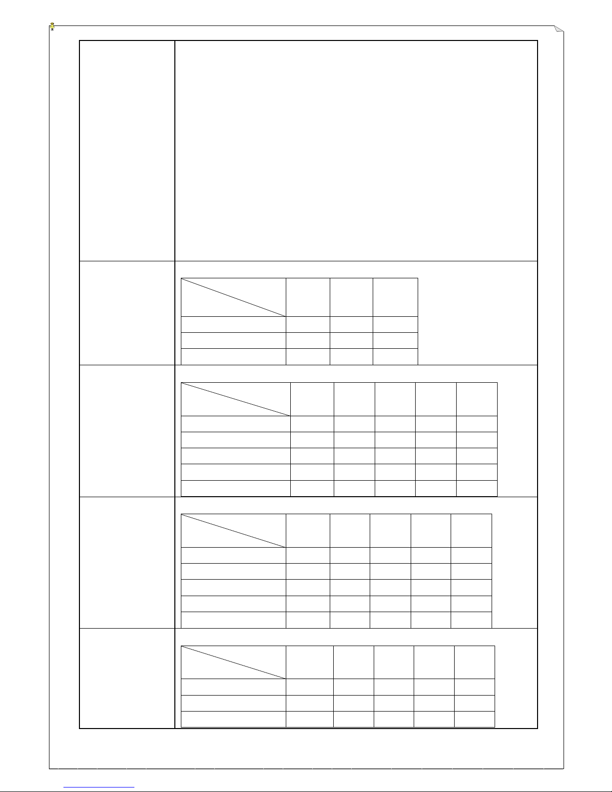
1-speed joystick
* Joystick back to zero check after transmitter startup
Neutral
relay
(optional)
Up
1-speed
relay
Down
1-speed
relay
Joystick neutral
ON
OFF
OFF
Joystick Up 1-speed
OFF
ON
OFF
Joystick Down 1-speed
OFF
OFF
ON
1-speed joystick
(Not share the 2nd
speed relay)
* Joystick back to zero check after transmitter startup
Neutral
relay
(optional)
Up
1-speed
relay
Up
2-speed
relay
Down
1-speed
relay
Down
2-speed
relay
Joystick neutral
ON
OFF
OFF
OFF
OFF
Joystick Up 1-speed
OFF
ON
OFF
OFF
OFF
Joystick Up 2-speed
OFF
ON
ON
OFF
OFF
Joystick Down 1-speed
OFF
OFF
OFF
ON
OFF
Joystick Down 2-speed
OFF
OFF
OFF
ON
ON
2-speed joystick
(Not share the 2nd
speed relay. 1st & 2nd
speed relays do not
activate at the same
time)
* Joystick back to zero check after transmitter startup
Neutral
relay
(optional)
Up
1-speed
relay
Up
2-speed
relay
Down
1-speed
relay
Down
2-speed
relay
Joystick neutral
ON
OFF
OFF
OFF
OFF
Joystick Up 1-speed
OFF
ON
OFF
OFF
OFF
Joystick Up 2-speed
OFF
OFF
ON
OFF
OFF
Joystick Down 1-speed
OFF
OFF
OFF
ON
OFF
Joystick Down 2-speed
OFF
OFF
OFF
OFF
ON
3-speed joystick
(2nd & 3rd speed
share the same relay)
* Joystick back to zero check after transmitter startup
Neutral
relay
(optional)
Up
relay
Down
relay
2-speed
relay
3-speed
relay
Joystick neutral
ON
OFF
OFF
OFF
OFF
Joystick Up 1-speed
OFF
ON
OFF
OFF
OFF
Joystick Up 2-speed
OFF
ON
OFF
ON
OFF
Page 15
15
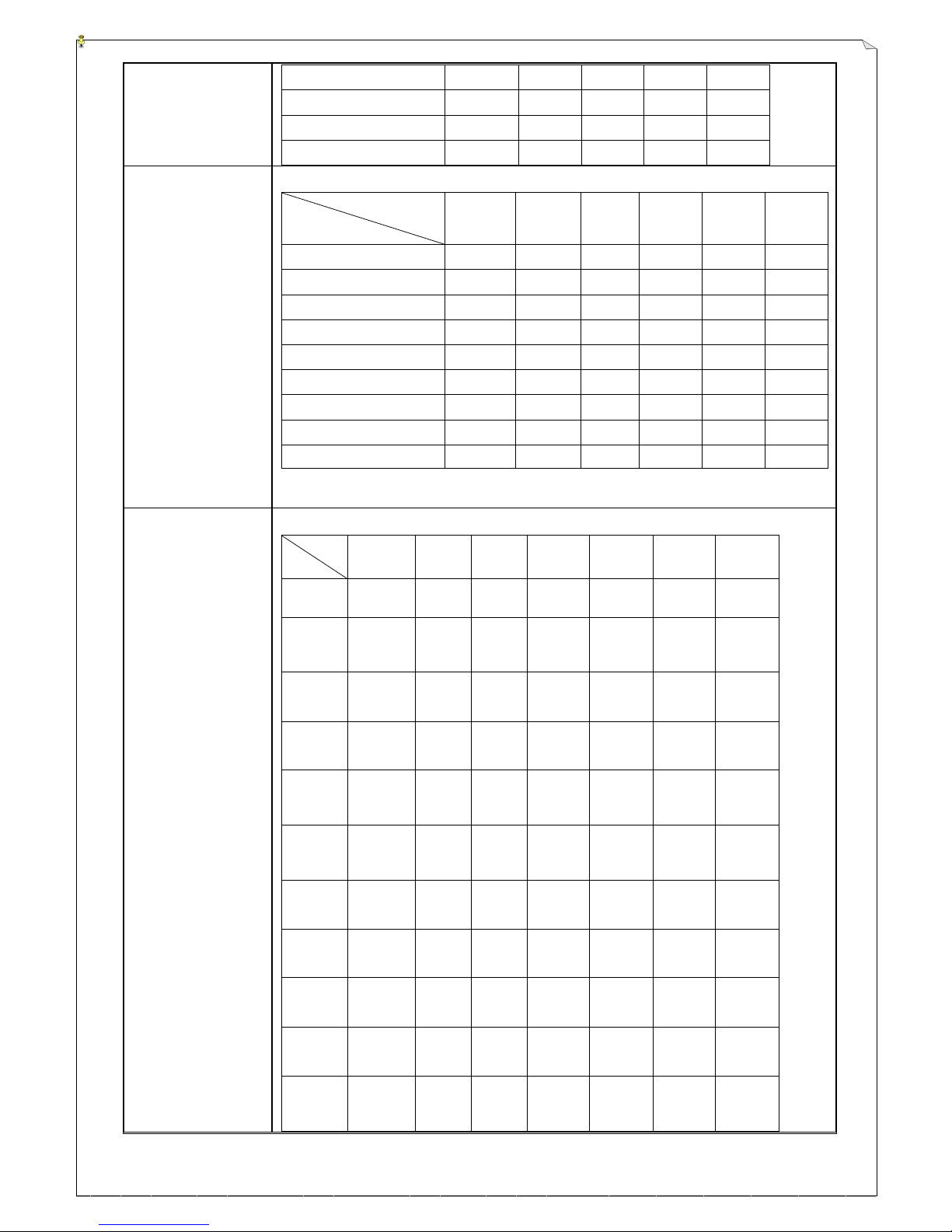
Joystick Up 3-speed
OFF
ON
OFF
ON
ON
Joystick Down 1-speed
OFF
OFF
ON
OFF
OFF
Joystick Down 2-speed
OFF
OFF
ON
ON
OFF
Joystick Down 3-speed
OFF
OFF
ON
ON
ON
4-speed joystick
(2nd, 3rd & 4th speed
share the same relay)
* Joystick back to zero check after transmitter startup
Neutral
relay
(optional)
Up
relay
Down
relay
2-speed
relay
3-speed
relay
4-speed
relay
Joystick neutral
ON
OFF
OFF
OFF
OFF
OFF
Joystick Up 1-speed
OFF
ON
OFF
OFF
OFF
OFF
Joystick Up 2-speed
OFF
ON
OFF
ON
OFF
OFF
Joystick Up 3-speed
OFF
ON
OFF
ON
ON
OFF
Joystick Up 4-speed
OFF
ON
OFF
ON
ON
ON
Joystick Down 1-speed
OFF
OFF
ON
OFF
OFF
OFF
Joystick Down 2-speed
OFF
OFF
ON
ON
OFF
OFF
Joystick Down 3-speed
OFF
OFF
ON
ON
ON
OFF
Joystick Down 4-speed
OFF
OFF
ON
ON
ON
ON
5-speed joystick
(2nd, 3rd, 4th & 5th
speed share the same
relay)
* Joystick back to zero check after transmitter startup
Neutral
relay
(optional)
Upper
relay
Lower
relay
2-speed
relay
3-speed
relay
4-speed
relay
5-speed
relay
Joystick
neutral
ON
OFF
OFF
OFF
OFF
OFF
OFF
Joystick
Up
1-speed
OFF
ON
OFF
OFF
OFF
OFF
OFF
Joystick
Up
2-speed
OFF
ON
OFF
ON
OFF
OFF
OFF
Joystick
Up
3-speed
OFF
ON
OFF
ON
ON
OFF
OFF
Joystick
Up
4-speed
OFF
ON
OFF
ON
ON
ON
OFF
Joystick
Up
5-speed
OFF
ON
OFF
ON
ON
ON
ON
Joystick
Down
1-speed
OFF
OFF
ON
OFF
OFF
OFF
OFF
Joystick
Down
2-speed
OFF
OFF
ON
ON
OFF
OFF
OFF
Joystick
Down
3-speed
OFF
OFF
ON
ON
ON
OFF
OFF
Joystick
Down
4-speed
OFF
OFF
ON
ON
ON
ON
OFF
Joystick
Down
5-speed
OFF
OFF
ON
ON
ON
ON
ON
Page 16
16
Outer extension,
1-speed joystick
Not included in the receiver 32pcs relays. The maximum number of outer extensive
relay is 32. Same function as 1-speed joystick.
Outer extension,
2-speed joystick
(Not to share the 2nd
speed relay)
Not included in the receiver 32pcs relays. The maximum number of outer extensive
relay is 32. Same function as 2-speed joystick. (not share the 2nd speed relay)
Outer extension,
2-speed joystick
(Not to share the 2nd
speed relay. 1st & 2nd
speed relays do not
activate at the same
time)
Not included in the receiver 32pcs relays. The maximum number of outer extensive
relay is 32. Same function as 2-speed joystick. (Not share the 2nd speed relay. 1st &
2nd speed relays do not activate at the same time)
Outer extension,
3-speed joystick
(2nd & 3rd speed
share the same relay)
Not included in the receiver 32pcs relays. The maximum number of outer extensive
relay is 32. Same function as 3-speed joystick. (2nd & 3rd speed share the same
relay)
Outer extension,
4-speed joystick
(2nd, 3rd & 4th speed
share the same relay)
Not included in the receiver 32pcs relays. The maximum number of outer extensive
relay is 32. Same function as 4-speed joystick. (2nd, 3rd & 4th speed share the same
relay)
Outer extension,
5-speed joystick
(2nd, 3rd, 4th & 5th
speed share the same
relay)
Not included in the receiver 32pcs relays. The maximum number of outer extensive
relay is 32. Same function as 5-speed joystick. (2nd, 3rd, 4th & 5th speed share the
same relay)
(#) VR = Variable Resistor
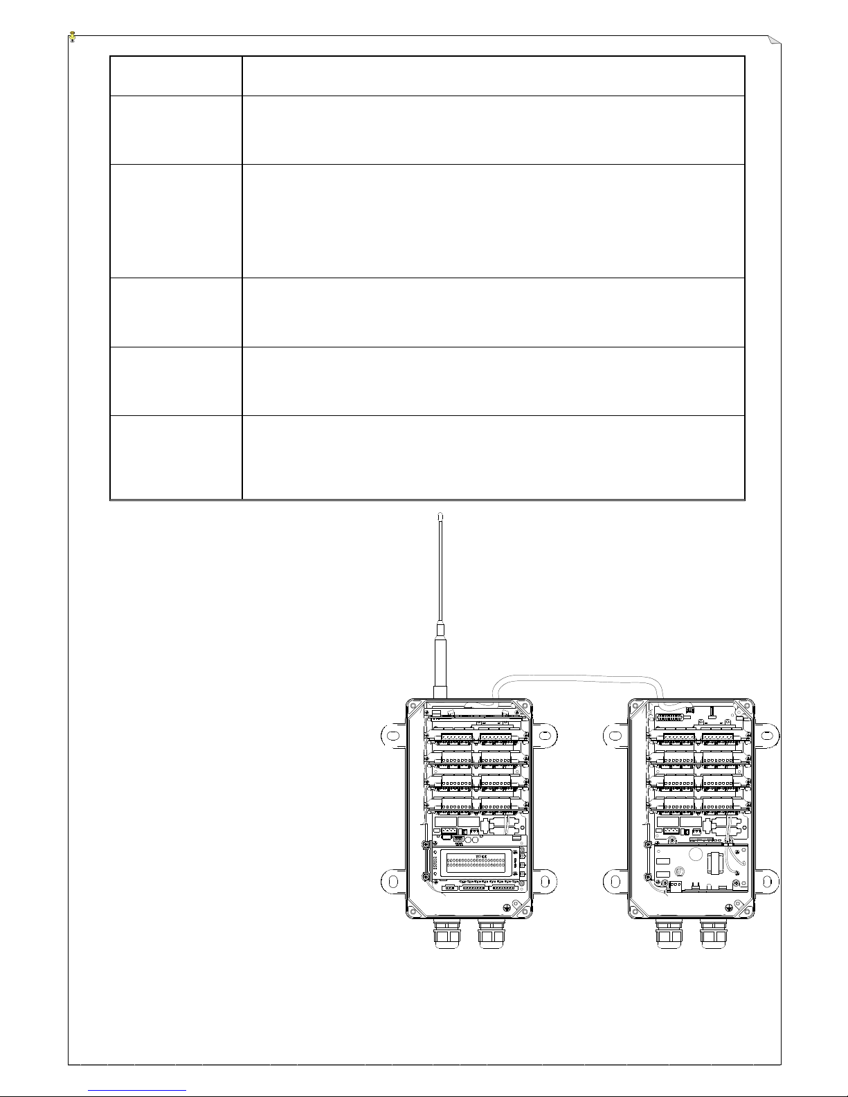
By using a 4-cord cable, you may connect
the main receiver (left) and the extension
one (right) as shown on below figure.
Please refer to “18. External Extension Contact”
of figure 10 on page 33 for the position of
connecting port.
Maximum number of relay for
extension receiver is 32pcs.
Please note that the extension receiver is only for
external extension only, not for main receiver.
Page 17
17
JOYSTICK
FUNCTION
REQUEST
DESCRIPTION
0~±10V
0~±5V
* Installation:
Interface card
for voltage/current
proportional
output. Please
make sure the
JUMPER in
front of the
output PORT is
plugged in the
V mark
position.
* Only for:
Proportional
joystick and
neutral type VR
Double axes proportional joystick:
* Neutral position as 0°, output 0V.
* Joystick Upper/Left axis 0° ~ +40° for 0 ~ +10V / 0~+5V
proportional output. (127 steps resolution)
* Joystick Lower/Right axis 0° ~ -40° for 0 ~ -10V / 0~-5V
proportional output. (127 steps resolution)
Single axis proportional joystick:
* Neutral position as 0°, output 0V.
* Joystick Upper axis 0° ~ +35° for 0 ~ +10V / 0 ~ +5V
proportional output. (127 steps resolution)
* Joystick Lower axis 0° ~ -35° for 0 ~ -10V / 0 ~ -5V
proportional output. (127 steps resolution)
Neutral type VR:
* 0° as rotating central position. Output 0V.
* Clockwise 0° ~ +120° for 0~+10V / 0~+5V proportional output.
(127 steps resolution)
* Counterclockwise 0° ~ -120° for 0~-10V / 0~-5V proportional
output. (127 steps resolution)
0~+10V
0~+5V
* Installation:
Interface card
for voltage/current
proportional
output. Please
make sure the
JUMPER in
front of the
output PORT is
plugged in the
V mark
position.
* Availability:
All are
available except
for the digital
joystick.
Double axes proportional joystick:
* Neutral position, output 0V. Upper and Lower axis relays are
OFF.
* Joystick Upper/Left axis 0° ~ +40° for 0~+10V / 0~+5V
proportional output. (127 steps resolution)
Upper axis relay is ON, Lower axis relay is OFF.
* Joystick Lower/Right axis 0° ~ -40° for 0~+10V / 0~+5V
proportional output. (127 steps resolution)
Upper axis relay is OFF, Lower axis relay is ON.
Single axis proportional joystick:
* Neutral position, output 0V. Upper and Lower axis relays are
OFF.
* Joystick Upper axis 0° ~ +35° for 0~+10V / 0~+5V proportional
output. (127 steps resolution)
Upper axis relay is ON, Lower axis relay is OFF.
* Joystick Lower axis 0° ~ -35° for 0~+10V / 0~+5V proportional
output. (127 steps resolution)
Upper axis relay is OFF, Lower axis relay is ON.
Neutral type VR:
* 0° as rotating central position, output 0V. Upper and Lower
axis relays are OFF.
* Clockwise 0° ~ +120° for 0~+10V / 0~+5V proportional output.
(127 steps resolution)
Page 18
18
Upper axis relay is ON, Lower axis relay is OFF.
* Counterclockwise 0° ~ -120° for 0~-10V / 0~-5V proportional
output. (127 steps resolution)
Upper axis relay is OFF, Lower axis relay is ON.
Single type VR:
* 0° as rotating central position, output 0V.
* Clockwise 0° ~ +240° for 0~+10V / 0~+5V proportional output.
(255 steps resolution)
0~20mA
0~24mA
* Installation:
Interface card
for voltage/current
proportional
output. Please
make sure the
JUMPER in
front of the
output PORT is
plugged in the I
mark position.
* Availability:
All are
available except
for the digital
joystick.
Double axes proportional joystick:
* Neutral position, output 0mA. Upper and Lower axis relays are
OFF.
* Joystick Upper/Left axis 0° ~ +40° for 0~20mA / 0~24mA
proportional output. (127 steps resolution)
Upper axis relay is ON, Lower axis relay is OFF.
* Joystick Lower/Right axis 0° ~ -40° for 0~20mA / 0~24mA
proportional output. (127 steps resolution)
Upper axis relay is OFF, Lower axis relay is ON.
Single axis proportional joystick:
* Neutral position, output 0mA. Upper and Lower axis relays are
OFF.
* Joystick Upper axis 0° ~ +35° for 0~20mA / 0~24mA
proportional output. (127 steps resolution)
Upper axis relay is ON, Lower axis relay is OFF.
* Joystick Lower axis 0° ~ -35° for 0~20mA / 0~24mA
proportional output. (127 steps resolution)
Upper axis relay is OFF, Lower axis relay is ON.
Neutral type VR:
* 0° as rotating central position, output 0mA. Upper and Lower
axis relays are OFF.
* Clockwise 0° ~ +120° for 0~20mA / 0~24mA proportional
output. (127 steps resolution)
Upper axis relay is ON, Lower axis relay is OFF.
* Counterclockwise 0° ~ -120° for 0~20mA / 0~-5V proportional
output. (127 steps resolution)
Upper axis relay is OFF, Lower axis relay is ON.
Single type VR:
* 0° in the left start position within rotating range. Output 0mA.
* Clockwise 0° ~ +240° for 0~20mA / 0~24mA proportional
output. (255 steps resolution)
4~20mA
* Installation:
Interface card
for voltage/current
proportional
output. Please
Double axes proportional joystick:
* Neutral position, output 4mA. Upper and Lower axis relays are
OFF.
* Joystick Upper/Left axis 0° ~ +40° for 4~20mA proportional
Page 19
19
make sure the
JUMPER in
front of the
output PORT is
plugged in the I
mark position.
* Availability:
All are
available except
for the digital
joystick.
output. (127 steps resolution)
Upper axis relay is ON, Lower axis relay is OFF.
* Joystick Lower/Right axis 0° ~ -40° for 4~20mA proportional
output. (127 steps resolution)
Upper axis relay is OFF, Lower axis relay is ON.
Single axis proportional joystick:
* Neutral position, output 4mA. Upper and Lower axis relays are
OFF.
* Joystick Upper axis 0° ~ +35° for 4~20mA proportional output.
(127 steps resolution)
Upper axis relay is ON, Lower axis relay is OFF.
* Joystick Lower axis 0° ~ -35° for 4~20mA proportional output.
(127 steps resolution)
Upper axis relay is OFF, Lower axis relay is ON.
Neutral type VR:
* 0° as rotating central position, output 4mA. Upper and Lower
axis relays are OFF.
* Clockwise 0° ~ +120° for 4~20mA proportional output.
(127 steps resolution)
Upper axis relay is ON, Lower axis relay is OFF.
* Counterclockwise 0° ~ -120° for 4~20mA proportional output.
(127 steps resolution)
Upper axis relay is OFF, Lower axis relay is ON.
Single type VR:
* 0° as the left start position within rotating range, output 4mA.
* Clockwise 0° ~ +240° for 4~20mA proportional output.
(255 steps resolution)
Customized
(OPTION)
proportional
output card
* Base on
customers’
requests
Base on customers’ requests
Neutral check
* Digital /
Proportional is
compelled to
have neutral
check
* Selectable at VR
When transmitter is ON, the joystick / VR has to be checked if it is
at 0° position, then transmitter can be started. If not, the error
status light will display as “pushbutton jammed / joystick is not at
neutral position” (Please refer to encoder status table.) and the
transmitter will not be started.
Plus/Minus
(+/-)voltage
exchange
* Only for
proportional
joystick or
neutral type
* Select 0~±5V or
0~±10V
Plus / Minus output reverse
Example:
Original => -5V(Lower axis)~ 0V(Neutral) ~(Upper axis)+5V
Select this function => +5V(Lower axis)~0V(Neutral)~(Upper
axis) -5V
Axis relay
* Not selectable:
single-side type
* There are 2pcs of relay for Axis relay. One is Upper/Left axis,
the other is Lower/Right axis.
Page 20
20
VR and digital
joystick
(digital joystick
is available with
axis relay)
* Joystick is at neutral position or when neutral type VR is at 0°
position, 2-axis relays are OFF.
* Joystick Upper/Left axis or neutral VR operates clockwise:
Upper/Left axis relay is ON, Lower/Right axis relay is OFF.
* Joystick Lower/Right axis or neutral VR operates counter-
clockwise:
Upper/Left axis relay is OFF, Lower/Right axis relay is ON.
* The proportional output voltage/current can be wired to
Upper/Lower axis relay at the same time. When the joystick is
moving, the proportional output voltage/current will output via
the corresponding axis.
Accelerating
output slowly
* Both joystick
and VR are
selectable
* Every joystick or
VR can be
selected
respectively or
not to select
* Example: Proportional joystick at 0~5V output, slowly output
time 3 seconds.
Operate joystick from neutral to top position swiftly and stop,
the output increases linearly from 0V, then gradually to 5V at the
3rd second and stops at 5V.
Accelerating
output slowly
time 1.5sec ~ 5sec
* Joystick
activates and
accelerates
slowly
* All joysticks and
VR with
activated
accelerating
output slowly
share this setting
time
* Time needed from the lowest output to the highest output.
Accelerating
output slowly:
immediately/slowly
* Joystick with
activated
accelerating
output slowly is
needed
* Joystick/VR spring return:
Decelerating immediately--
Output corresponds to the current joystick/VR angle
immediately.
Decelerating slowly--
Base on the time selected for accelerating output slowly,
output decreases proportionally from previous setting to
current joystick/VR angle.
Joystick neutral
relay
* Joystick/VR are
selectable
* Joystick in the neutral position, neutral relay ON; Joystick is not
in the center position, neutral relay OFF.
* Neutral type VR: Within center position of rotating range,
neutral relay ON; Out of center position of rotating range,
neutral relay OFF.
* Single type VR: VR in the left START position, neutral relay
ON; VR is not in the left START position, proportional output
activated and neutral relay OFF.
Joystick neutral
relay output
reversely
* After joystick
neutral relay is
activated
* Neutral relay reverse
Joystick
direction
Up/Down or
* For digital and
proportional
* Joystick Up axis is changed to Down axis and Down axis is
changed to Up axis.
Page 21
21
Left/Right
exchange
joystick only
Not to select:
1.Left cross axis: Up/Down axis
2.Left cross axis: Left/Right axis
3.Right cross axis: Left/Right axis
4.Small single axis
To select:
Right cross axis: Up/Down axis
Joystick share
the same
accelerator relay
* Joystick/VR are
selectable
* The selected joystick or VR share the same relay.
* Either the selected joystick or VR is not in the center/
0° position (with output), the relay with joystick share the same
accelerator is ON.
* The selected joystick or VR is back to the center/0° position, the
relay with joystick share the same accelerator is OFF.
Opposite side
protection of
joystick spring
return
* For digital and
proportional
joysticks only.
* For cross type
joystick, not for
small single axis
joystick.
* When the joystick is back to neutral position, if the spring inertia
is too strong, then the joystick will spring back to the opposite
position. But the opposite relay output will be inhibited.
Assign the 8th
axis as the output
that share the
same accelerator
* Digital joystick
without this
function
* All the activated
joysticks/VR
with the same
style
* Not to use the
8th joystick/VR
(reserved for
sharing the
same
accelerator
output)
* The 8th joystick/VR are reserved for sharing the same
accelerator output. Not to use for general joystick.
* Joystick/VR share the same accelerator output is the same as the
selected joystick or VR as highest output “absolute value”.
(output always with plus voltage).
* The selected joystick or VR is back to neutral /0° position,
joystick/VR share the same accelerator analog output back to
neutral/0° position output.
8 joysticks allow
only one function
at the same time
* Either cross type
joystick
restriction or this
function can be
selected
* When “joystick/VR share the same accelerator analog output” is
not considered, only 1 out of 8 with output.
* 1~8 joysticks/VR, detect from joystick/VR 1 to 2,3~8. At last,
the joystick function first with output (joystick or VR not on
neutral/0° position), the rest without output. When “all
joystick/VR (including the one without function)” back to
neutral/0° position, output back to neutral/0° position and start
again.
Cross type
joystick
restriction
* Joystick only
* Only 1 out of 8
single axis
joysticks is
allowed to
function
independently.
* Restriction for
each two
* Take 1-2 cross type joystick restriction as an example:
Joystick 1&2 without neutral but with output and another
joystick output is not allowed (1&2 joystick without neutral at
the same time, joystick 1 has the priority). When joystick 1&2
back to neutral, output back to neutral position and start again.
Page 22

22
joysticks 1-2,
3-4, 5-6 & 7-8.
SICK LASER
* Single side VR
is not selectable
* SICK LASER “NORTH” is restricted to Up axis. The purpose
is for the very north positioning.
* SICK LASER “SOUTH” is restricted to Down axis. The
purpose is for the very south positioning.
* Joystick 1 is to the detecting point of CN13 1N(Up axis)/1S(Down) input.
* Joystick 2 is to the detecting point of CN13 2N(Up axis)/2S(Down) input.
* Joystick 3 is to the detecting point of CN13 3N(Up axis)/3S(Down) input.
* Joystick 4 is to the detecting point of CN13 4N(Up axis)/4S(Down) input.
* Joystick 5 is to the detecting point of CN14 5N(Up axis)/5S(Down) input.
* Joystick 6 is to the detecting point of CN14 6N(Up axis)/6S(Down) input.
* Joystick 7 is to the detecting point of CN14 7N(Up axis)/7S(Down) input.
* Joystick 8 is to the detecting point of CN14 8N(Up axis)/8S(Down) input.
* CN2 +0V supplies trigger purpose power level.
Example:
0~±10V output, SENSORs are equipped on the North/South end
of crane rail.
When the crane does not reach the North SENSOR, the input
detecting point that is sent from SENSOR to CN13 1N will not be
triggered;
When the crane reaches the North SENSOR, the SENSOR will
send detecting point 0V to CN13 1N input;
When the crane does not reach the South SENSOR, the input
detecting point that is sent from SENSOR to CN13 1S will not be
triggered;
When the crane reaches the South SENSOR, the SENSOR will
send detecting point 0V to CN13 1S input.
When joystick is operated to the Up axis position, the crane will
go to North. Before joystick reaches the North SENSOR, the
detecting point of CN13 1N input will not be triggered. The
output will depend on joystick Up axis angle 0~+10V. Crane will
go to North position continuously.
When crane reaches the North SENSOR, the detecting point of
CN13 1N input will be 0V. The decoding firmware will be
restricted as the North output. That is, when joystick is operated
to Up axis position, the output will be 0V. Then crane cannot go
to North position anymore.
When joystick is operated to the Down axis position, the crane
will go to South. Before crane reaches the South SENSOR, the
detecting point of CN13 1S input will not be triggered. The
output will depend on the angle 0~ -10V of joystick Down axis.
Crane will go to South position continuously.
Page 23
23
When crane reaches the North SENSOR, the detecting point of
CN13 1S input will be 0V. The decoding firmware will be
restricted as South output. That is, when joystick is operated to
Down axis position, the output will be 0V. Then crane cannot go
to South anymore.
Selection of
linear output
curve: linear
* For proportional
joystick and VR
only
* The tilt percentage for input and output is fixed. Output from
neutral to maximum value is a straight line.
* Joystick/VR angle output corresponds to the tilt percentage of
this straight line.
Selection of
linear output
curve: curve
* For proportional
joystick and VR
only
* Forward/reverse parabola curves may be changed by dragging
mouse.
* Joystick/VR angle output corresponds to this curve.
Selection of
linear output
curve: logic
* For proportional
joystick and VR
only
* Output status is only available with neutral and highest level, no
in between one.
* Joystick moves/VR rotates to ”certain angle”, the output from
neutral immediately to highest point of the axis.
* Certain angle: changeable by dragging the mouse.
Non-symmetry
* For proportional
joystick and
neutral VR only
* Select “curve”
or “logic”
* Up/Down axis setting is independent.
Page 24
24
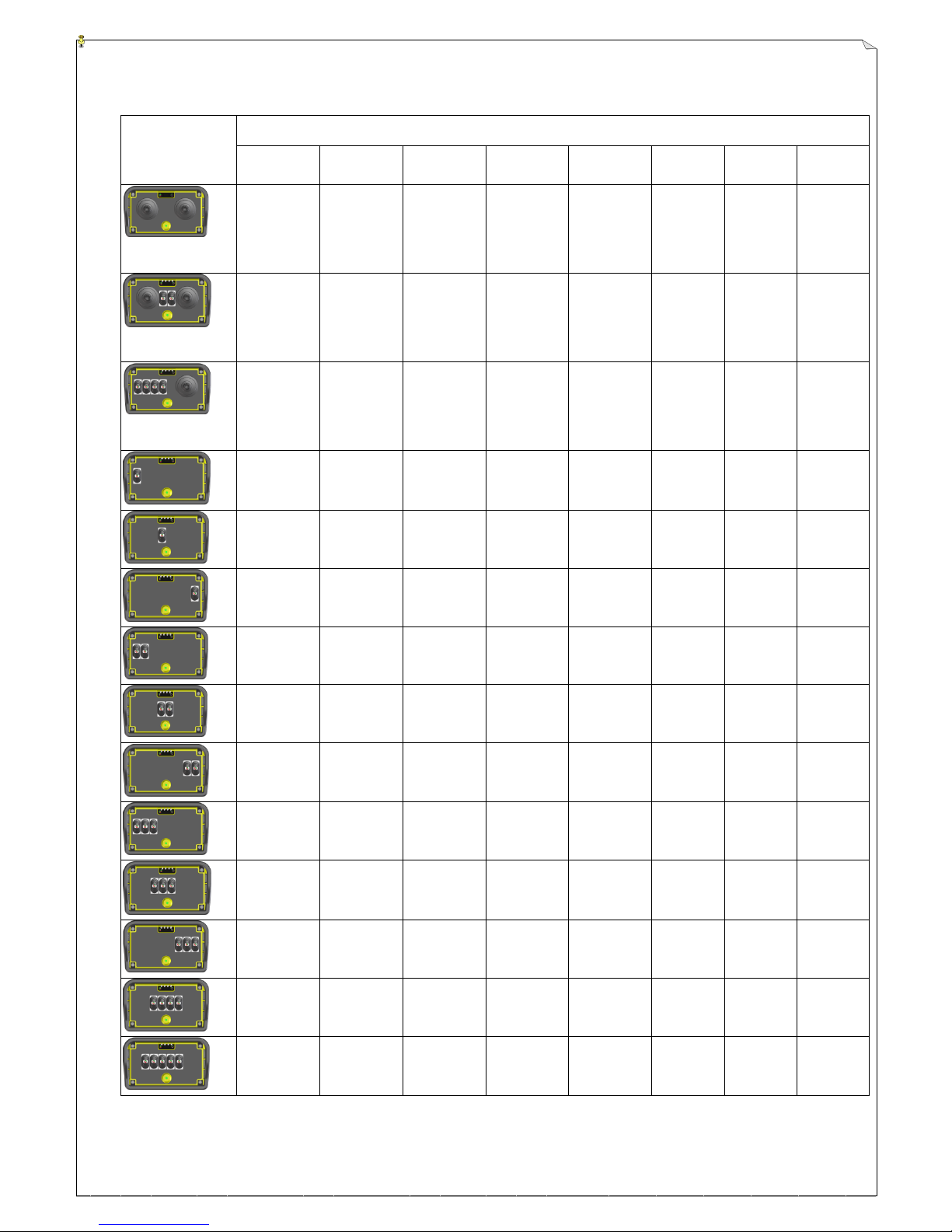
4.2 Joystick Configurations and Settings
JOYSTICK
SETTING
Joystick1
Joystick2
Joystick3
Joystick4
Joystick5
Joystick6
Joystick7
Joystick8
Left double
axis type
Up/Down
axis
Left double
axis type
Left/Right
axis
Right double
axis type
Up/Down
axis
Right
double axis
type
Left/Right
axis
Left double
axis type
Up/Down
axis
Left double
axis type
Left/
Right axis
(Left) small
single axis
(Right) small
Right double
axis type
Up/Down
axis
Right
double axis
type
Left/Right
axis
(A) small
single axis
(B) small
single axis
(C) small
single axis
(D) small
single axis
Right double
axis type
Up/Down
axis
Right
double axis
type
Left/Right
axis
small single
axis
small single
axis
small single
axis
(A) small
single axis
(B) small
single axis
(A) small
single axis
(B) small
single axis
(A) small
single axis
(B) small
single axis
(A) small
single axis
(B) small
single axis
(C) small
single axis
(A) small
single axis
(B) small
single axis
(C) small
single axis
(A) small
single axis
(B) small
single axis
(C) small
single axis
(A) small
single axis
(B) small
single axis
(C) small
single axis
(D) small
single axis
(A) small
single axis
(B) small
single axis
(C) small
single axis
(D) small
single axis
(E) small
single axis
Page 25
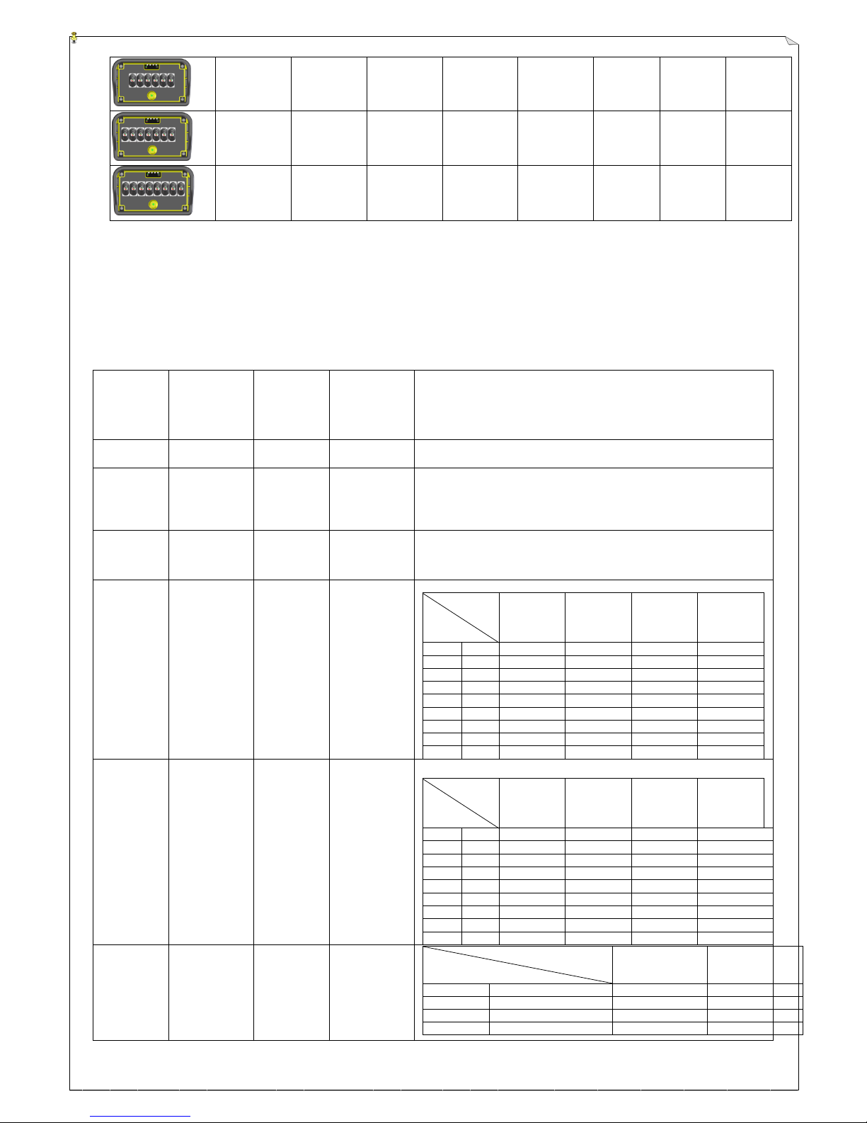
25
(A) small
single axis
(B) small
single axis
(C) small
single axis
(D) small
single axis
(E) small
single axis
(F) small
single axis
(A) small
single axis
(B) small
single axis
(C) small
single axis
(D) small
single axis
(E) small
single axis
(F) small
single axis
(G) small
single axis
(A) small
single axis
(B) small
single axis
(C) small
single axis
(D) small
single axis
(E) small
single axis
(F) small
single axis
(G) small
single axis
(H) small
single axis
When right cross type joystick is applied, the software setting for Joystick5 should be: Joystick
direction [Up/Down] or [Left/Right] has to be exchanged.
4.3 Transmitter Pushbutton Descriptions
4.3.1 Pushbutton Types:
Pushbutton
Type
Not control
by EMS
button
Pushbutton
share the
same
accelerator
relay
Transmitter
start without
checking if
pushbutton is
locked
Function
Single speed
Software
selectable
Software
selectable
Software
selectable
* Without pressing pushbutton, relay OFF
Press pushbutton, relay ON
Double speed
“Press EMS and
compel double
speed relay
open” is not
selectable
Software
selectable
Software
selectable
* Without pressing pushbutton: 1-speed relay OFF , 2-speed relay OFF
* Press pushbutton 1-speed: 1-speed relay ON , 2-speed relay OFF
* Press pushbutton 2-speed: 1-speed relay ON , 2-speed relay ON
Single speed
in pairs,
interlocke
d
Software
selectable
Software
selectable
Software
selectable
* Two single-speed pushbuttons, each pushbutton has one relay. Two
interlocked relays are not ON at the same time.
Double speed
in pairs,
interlocked
“Press EMS and
compel double
speed relay
open” is not
selectable
Software
selectable
Software
selectable
PB 2 PB 1
PB 1
1-spd relay
PB 1
2-spd relay
PB 2
1-spd relay
PB 2
2-spd relay
OFF
OFF
OFF
OFF
OFF
OFF
OFF
1-spd
ON
OFF
OFF
OFF
OFF
2-spd
ON
ON
OFF
OFF
1-spd
OFF
OFF
OFF
ON
OFF
2-spd
OFF
OFF
OFF
ON
ON
1-spd
1-spd
OFF
OFF
OFF
OFF
2-spd
1-spd
OFF
OFF
OFF
OFF
1-spd
2-spd
OFF
OFF
OFF
OFF
2-spd
2-spd
OFF
OFF
OFF
OFF
Double speed
in pairs,
inter-locked,
2-speed
separate
“Press EMS and
compel double
speed relay
open” is not
selectable
Software
selectable
Software
selectable
PB2 PB1
PB 1
1-spd relay
PB 1
2-spd relay
PB 2
1-spd relay
PB 2
2-spd relay
OFF
OFF
OFF
OFF
OFF
OFF
OFF
1-spd
ON
OFF
OFF
OFF
OFF
2-spd
OFF
ON
OFF
OFF
1-spd
OFF
OFF
OFF
ON
OFF
2-spd
OFF
OFF
OFF
OFF
ON
1-spd
1-spd
OFF
OFF
OFF
OFF
2-spd
1-spd
OFF
OFF
OFF
OFF
1-spd
2-spd
OFF
OFF
OFF
OFF
2-spd
2-spd
OFF
OFF
OFF
OFF
ON/OFF in
pairs
Software
selectable
“No
function ”is
not
selectable
Software
selectable
OFF PB ON PB
ON PB relay
OFF PB relay
Never press
Never press
OFF
ON
Not press
Press
ON
OFF
Press
Not press
OFF
ON
Press
Press simultaneously
OFF
ON
Page 26
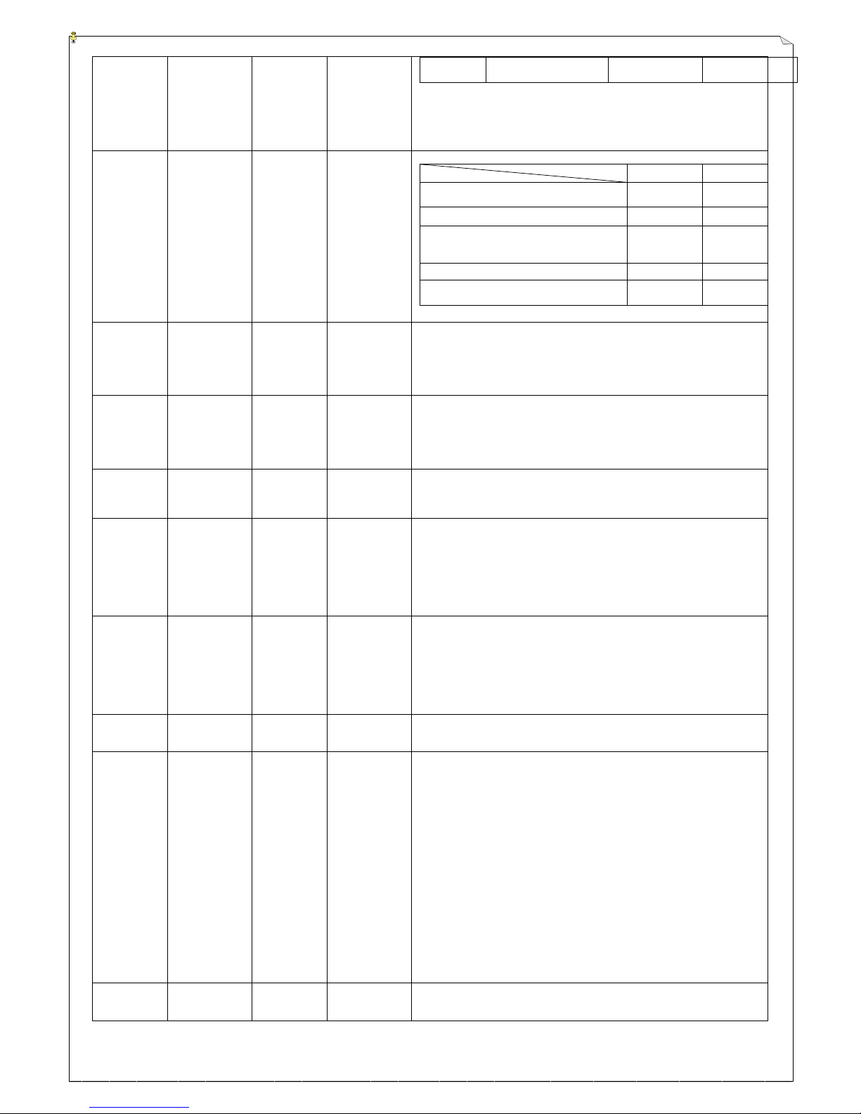
26
simultaneou
sly
ON/safe OFF
in pairs
“EMS not to
deactivate” is
not selectable
“No
function ”is
not selectable
Software
selectable
ON PB relay
OFF PB relay
Receiver power on (Before receiving signal
from transmitter)
OFF
ON
Not to press OFF PB , press ON PB
ON
OFF
1. Not to press OFF & ON PB
2. Not to press ON PB and depress OFF PB
3. Depress OFF PB and press ON PB
OFF
ON
Press OFF & ON PB at the same time
Same status
Same status
Press EMS button or receiver receives no
signal from transmitter
Same status
Same status
Toggle
switch. Press
EMS button
and MAIN
relay remains
activate
“EMS not to
deactivate” is
not selectable
“No
function ”is
not selectable
Software
selectable
* Press button and relay become OFF to ON or ON to OFF.
* Press EMS button or receiver receives no signal from transmitter, relay
remains latched.
Toggle
switch. Press
EMS button
and MAIN
relay
deactivates
“Press EMS and
compel toggle
switch relay
open” is not
selectable
“No
function ”is
not selectable
Software
selectable
* Press button and relay become OFF to ON or ON to OFF.
* Press EMS button or receiver receives no signal from transmitter, relay off.
2nd EMS
button
Software is not
selectable
“No
function ”is
not selectable
“Compulsory
check” is not
selectable
* Receiver power ON, if no signal is received, 2nd EMS relay will be OFF.
* After transmitter is ON (no to press dual EMS button), relay ON.
* Press dual EMS button relay OFF.
* Not to press dual EMS button but press START button, relay ON.
Standard
selector
switch. Press
EMS button
and standard
selector
switch relay
close
“EMS not to
deactivate” is
not selectable
“No
function ”is
not selectable
Pre-set as “No
check” is
selectable
* Switch ON, relay ON; switch OFF, relay OFF.
* Press EMS button or receiver receives no signal from transmitter, standard
selector switch relay off.
Standard
selector
switch. Press
EMS and
standard
selector
switch relay
open
“Press EMS and
compel standard
selector switch
relay open” is
not selectable
“No
function ”is
not selectable
Pre-set as “No
check” is
selectable
* Switch ON, relay ON; switch OFF, relay OFF
* Press EMS button or receiver receives no signal from transmitter, relay off.
Speed limit
switch
“No function ”is
not selectable
“No
function ”is
not selectable
“No check
compelled” is
not selectable
* Switch types selectable: 3-position or 3-stage rotary selector switch.
* The joystick/VR output can be changed by the 3-stage limit switch
* 1st stage output 25%, 2nd stage output 50% & 3rd stage output 100%.
Mix mode
selector
switch
“No function ”is
not selectable
“No
function ”is
not selectable
* 1 wire to 1
switch:
software
non-selectable,
compel to
check
* 3 wires
encoding type:
software is not
selectable,
compel not to
check
* Each stage of 2~8 stage selector switch may change function for CHANNEL,
LID & EID.
* Switch condition- 1 wire to 1 switch: 2-stage rotary selector switch to 2 wires,
3-stage to 3 wires…, 8-stage to 8 wires.
* Switch condition- 3-wire encoding type, 8-stage: 3 wires to 8-stage rotary
selector switch. Non-changeable.
* Switch condition – change directly: The stage of rotary selector switch is
changed, transmitter is set to the CHANNEL/LID/EID of that stage.
* Switch condition- Re-start the power to change: The setting position of rotary
selector switch is used after transmitter power is ON. No other stage of
rotary selector switch can be used only after next time transmitter power is
ON.
* Switch condition- Press START to change: Press START and use the current
CHANNEL/LID/EID setting on rotary selector switch.
* Use channel selection to assign channel on each stage.
* Select EID ENABLE then to either assign EID on each stage or set EID on
pushbutton.
* Select LID ENABLE then to either assign LID on each stage or set LID on
pushbutton.
Group mode
selection
switch
“No function ”is
not selectable
“No
function ”is
not selectable
“Compulsory
check” is not
selectable
* Stage available: 2~8-stage rotary selector switch (wiring: 1 wire to 1 stage)
* Select relay of each stage from relay 1~8.
* Different stage may assign the same relay repeatedly.
Page 27
27
EID switch
“No function ”is
not selectable
“No
function ”is
not selectable
“No check
compelled” is
not selectable
* Change transmitter EID b0~b3
* Switch ON, EID bit=1; switch OFF, EID bit=0.
* Either mix mode selector switch or EID ENALE is selectable
* Receiver with AUTOSCAN function select EID bit match or bit or function
LID switch
“No function ”is
not selectable
“No
function ”is
not selectable
“No check
compelled” is
not selectable
* Change transmitter LID b0~b3
* Switch ON, LID bit=1; switch OFF, LID bit=0.
* Only 1 out of 2 LID ENALE function is selectable for mix mode selector
switch
Digital
joystick 2~5
speeds
activating
button
“No function ”is
not selectable
“No
function ”is
not selectable
“Pre-checking”
is selectable
* Select the pushbutton so that the pushbutton may control the digital joystick.
* When the pushbutton is not depressed, only 1-speed is activated even if the
joystick is operated to 2~5 speeds.
* Joystick 2~5 speeds only activated with relay output when the pushbutton is
depressed without releasing.
* Maximum 4pcs pushbuttons.
* Pushbutton or auto-return toggle switch is acceptable. No corresponding
relay output.
* If the digital joystick is not controlled by this pushbutton, then the 2~5 speeds
is not limited at 1 speed.
* EMS button: In case of an emergency, press down the red emergency stop button (EMS) will immediately
deactivates the transmitter and receiver MAIN relay. This is the rotary return type.
After the emergency stop button is elevated, please refer to “Transmitter startup condition” on Page 28 to
restart.
EN ISO 13849-1 type: Press emergency stop button and switch off the transmitter power immediately,
then the transmitter will stop sending commands. After the receiver is not receiving any signal for 1
second, MAIN relay will be off.
Regular type: Press emergency stop button and the transmitter will be sending emergency stop command.
As soon as the receiver receives stop command, the MAIN relay will be off. When the emergency stop
button is pressed for more than 1.5 seconds, the transmitter power will be switched off automatically.
* START button: Press to start the system and activate the receiver MAIN relay at the same time
* KEY: Power switch
4.3.2 Function Settings:
* ID: Range 00000~FFFF (hex), length 20bit. Total 1,048,576 sets of unique ID codes. Each Alpha 6000
system with unique manufacturing ID setting. This will ensure that only commands from the matching
control transmitter can be carried out without any interference from other radio systems.
Remark 1: ID with 4 lower digit b[3:0] is called LID
Remark 2: Transmitter with function ”mix mode selector switch-LID function” or “LID switch” will replace the original LID.
Remark 3: Receiver with function ”LID bit match” or ”LID bit ” from AUTOSCAN will replace the original LID.
* Channel: The channel in use assigned
Remark 1: transmitter with function “mix mode selector switch-channel in use function” or ”intelligent channel change” will
replace the original channel in use.
Remark 2: Receiver with channel assigned from AUTOSCAN will replace the original channel in use.
* Service number: Alpha 6000 manufacturing serial number, for after service purpose.
* Manufacturing date: manufacturing date
* Customer remark: 16 alphabets or numbers recordable
Page 28
28
4.3.2.1 Transmitter Function Settings
* Transmitter startup condition:
◎ Power key startup: Rotate the power key clockwise to “ON” position to turn on the transmitter power.
◎ START button/press START to activate MAIN relay: Rotate the power key clockwise to “ON” position,
then press START to turn on the transmitter power.
* Transmitter power on, EMS button press / release function compel to check
◎ Not enable:
◎ Enable: After transmitter power is turned on and before EMS button is not depressed, the status LED is
displayed as: green LED ON_0.1sec, OFF_0.9sec blink. Depress EMS button and elevate it to re-start the
transmitter. This is to ensure no function error on EMS button before operation.
Remark: After transmitter power is turned on, the status LED is displayed as “green LED ON_0.1sec,OFF_0.9sec blink”. It
means transmitter power is turned on and EMS button press/release function is checked.
* Transmitter inactivity overtime and then enter sleep mode:
◎ Immediate : No press down pushbutton and joystick back to neutral, the transmitter will enter sleep
mode immediately.
◎ 1~120mins : No press down pushbutton and joystick back to neutral, after 1~120mins (selectable)/
5 minutes manufacture setting, the transmitter will enter sleep mode immediately.
◎ No auto shutdown/never shutdown: Transmitter without sleeping mode.
Remark : Transmitter enter sleep mode- Status LED OFF, power green LED ON, RF module and A/G sensor module OFF, then
enter power saving mode.
* After transmitter enter sleep mode, re-awakening condition:
◎ Re-start: Power key -> OFF -> ON
◎ Joystick /any pushbutton: Pushbutton is pressed or joystick/VR is operated/rotated or power key ->
OFF -> ON
◎ START button: Joystick is back to neutral position and release pushbutton. Press START button to
awaken transmitter. (Press START button when joystick is not in neutral position or
pushbutton is pressed, red status LED on and transmitter cannot be awakened)
* Abnormal buss from transmitter:
◎ Not enable: Buzz from transmitter START/LV/joystick correction no need to enable.
◎ Enable: Buzzer sound when transmitter error status LED is flash.
* Transmitting power
◎ –2~+20 dbm: Default setting is based on the transmitting power where the area/country is regulated.
For any changes, please note if the setting meet the requirement of area/country.
* Transmitter drop protection:
◎ Not enable:
◎ Enable: If transmitter drops during operation, transmitter will send emergency stop signal to
receiver and MAIN relay will be OFF. (Transmitter should equip with A/G SENSOR
module)
◎ Sensitivity -3 ~ +3 : Range of sensitivity adjustment for dropping detection. The
sensitivity is pre-set as standard one.
Page 29
29
◎ Shutoff transmitter power: When transmitter drops over the range of detective
sensitivity, signal transmission from transmitter to
receiver will be shutoff. Buzzer and error status LED
display will continue to warn the operator. MAIN relay
will be deactivated after the receiver receives no signal
from the transmitter.
Re-start the transmitter:
1. Rotate the power switch to ‘OFF’ position and then ‘ON’ and start the transmitter
again.
2. Press the emergency stop button, elevate it again and then start the transmitter
again.
◎ Inhibit the joystick and button functions:
When transmitter drops to the sensor sensitivity limit, control actively to all the
joysticks in use to become neutral output status. VR output remains on the point where transmitter is
dropped. Pushbutton types that control automatically: single speed / single speed interlock / double speed /
double speed interlock pushbuttons are all released. Other pushbuttons or switches output remains locking
on the status of transmitter dropping. The transmitter buzzer and error status light will be ON continuously
to warn the operator.
To release joystick and pushbutton function:
a. To release joystick and pushbutton function, when joysticks are neutral (*) and pushbuttons / switches
are released, press START button to release “Inhibit the joystick and button functions”. (* VR output
remains on the point where transmitter is dropped and cannot be changed until START button is pressed,
transmitter is switched off or EMS is pressed)
b. Press EMS button and release, then start the system again by following the “Transmitter boot condition”.
* Transmitter tilt protection:
◎ Not enable:
◎ > ±30°~±50°:
Transmitter in operation, when the tilt angle is bigger than default setting, the transmitter will send
emergency stop signal to the receiver and MAIN relay will be OFF. (Transmitter should equip with
an A/G SENSOR module) The initial press angle of the transmitter power / START button is
defined as 0∘.
◎ Switch off transmitter power:
When the transmitter tilt angle is bigger than the default setting, the signal transmission from
transmitter to receiver will be disabled automatically. The transmitter buzzer and error status LED
will be ON continuously to warn the operator that the receiver cannot receive any signal from the
transmitter and the MAIN relay will be deactivated. To restart the transmitter, rotate the power
switch to OFF and then to ON position. Then start the system again by following the “Transmitter
boot condition”.
◎ Inhibit the joystick and pushbutton function:
When the transmitter tilt angle is bigger than the default setting, all the joysticks will be inhibited as
neutral output status automatically. VR output remains at the point where transmitter is dropped.
Pushbutton types that control automatically: single speed / single speed interlock / double speed /
Page 30
30
double speed interlock pushbuttons are all released. The transmitter buzzer and error status light
will be ON continuously to warn the operator. To release the inhibited joystick and pushbuttons
function by the error status light:
1. To release “Inhibit the joystick and pushbutton function“, press START button when the joystick
position is neutral (unrelated to VR) and pushbutton is released. The transmitter buzzer and error
status light will be OFF then back to normal operation.
2. After the emergency stop button is elevated, start the system again by following the “Transmitter boot
condition”.
Note: Transmitter drop and tilt protection are sharing the same method.
* Transmitter transmission intermittently
◎ Not enable: Transmitter sends signal 10 times every second.
◎ Enable: Transmitter sends signal 4 times every second.
* Transmitter battery replacement, auto-recovery
◎ Not enable:
◎Enable: The batteries can be replaced during transmitter operation. (without pressing EMS button or
turning off the power) After the batteries are replaced, the transmitter can be operated
normally. Transmitter START button startup and EMS button press/release check will be omitted.
Remark: This function is only for the transmitter. When the battery is removed from the transmitter, there will be no signal on the
receiver and MAIN relay will be deactivated.
A. If “receiver MAIN activate term: ID matches” is selected: Signal will be sent as soon as transmitter battery is inserted.
When ID matches and receiver receives signal from the transmitter, MAIN relay will be activated.
B. If “receiver MAIN activate term: START button” is selected: Signal will be sent as soon as transmitter battery is
inserted. When ID matches and receiver receives signal from the transmitter, MAIN relay will not be activated until
START button is pressed.
* Transmitter power ON, emergency stop button press/release check
◎ Not enable:
◎ Enable: After the transmitter power key is rotated to ON position and before the emergency stop
button is pressed, the LED status: green LED blinks ON_0.1sec, OFF_0.9sec. Press and
release emergency stop button, then transmitter will be started. This is to ensure the
emergency stop button function without problem before transmitter operation.
4.3.2.2 Receiver Function Settings
* Receiver MAIN relay activate condition
◎ ID match: Transmitter and receiver ID is identical
◎ START button: Make sure transmitter and receiver ID is identical, then press START button on the
transmitter.
* Receiver MAIN relay dynamic check
◎ Not enable:
◎ Enable: Before MAIN relay is ON, first proceed with dynamic check. If pass, then MAIN relay is
Page 31
31
ON; if NG, then error status “MAIN relay lock” appear.
◎ Receiver power ON: Proceed with dynamic check when receiver power is ON. If pass, then start
the system; if NG, then error status “MAIN relay lock” appear.
◎ START and receiver power ON: Dynamic check for both operation and power ON conditions.
Remark 1: When MAIN relay is on dynamic check status, MAIN1 relay close and MAIN2 relay open. After MAIN1
relay feedback normally, MAIN2 relay close and MAIN1 relay open, then check MAIN2 relay
feedback.
* Receiver channel auto-scan
◎ Not enable: Receiver receives channel regularly
◎ Enable and transmitter power ON enables intelligent channel change: “receiver auto-scan
channels” and “transmitter power ON intelligent channel change” activate at the same
time.
Transmitter power On intelligent frequency change:
1. When the software setting is started, there will have 8 channels available automatically. The 8
channels are used for receiver auto scanning and the transmitter can also select the best
communication channel from them.
2. It takes 1~3 seconds for every channel selection when transmitter is started. Time for receiver
channel auto scanning is 1~6 seconds. (pre-set as master / slave channel exchange scanning
mode)
3. Transmitter encoder version has to be V02.08 (incl.) or above and setting software has to be
V03.05 (incl.) or above.
◎ Enable Channel stage selection:
2~16 stages are available. Each stage may assign receiving channel, LID & EID.
Delay time for entering auto-scan channel:
0~3 seconds are available. Before entering channel auto-scan, the search will stay for
0~3 seconds at the original channel (optional). If transmitter signal is received and
matches the frequency auto-scan lock condition, then the system enters operation status
again. If delay time over 0~3 seconds, the system will enter frequency auto-scan status
again.
Master/slave channel auto-scan exchange mode:
Master channel is the previous channel in use; the rest 1~16 channels are slave
channels.
Master/salve channel auto-scan exchange sequence: Master channel ->1st setting channel -> Master channel ->
2nd setting channel ……… Master channel -> Last setting channel
↑___________________________________________________________________|
Non-master/slave channel auto-scan exchange sequence: 1st setting channel ->2nd setting channel ………
Last setting channel
↑______________________________________________|
◎ Auto-scan lock, LV relay ON for 3 seconds: Enable LV relay first to select. The function is the
same as ALARM relay.
Page 32
32
◎ Auto-scan master channel lock condition
ID match_It is used only for master channel under auto-scan condition which transmitter
ID matches receiver one.
START button_It is used only for master channel under auto-scan condition which transmitter
ID matches receiver one. The transmitter START button has to be pressed down at the same
time.
◎ Auto-scan slave channel lock condition
ID match: It is used only for slave channel under auto-scan condition which transmitter ID
matches receiver one.
START button: It is used only for slave channel under auto-scan condition which transmitter
ID matches receiver one. The transmitter START button has to be pressed down at the same
time.
◎ Slave channel lock time: 0~3 seconds. (optional) Only when auto-scan slave channel is locked
for 0~3 seconds, then it is confirmed to be locked. (MAIN RELAY ON)
◎ LID Disable: Not in use
Bit match: The LID setting within 1~16 stages will replace the original LID of ID and
become new 20bit ID. The 20bit ID has to be identical to the ID received.
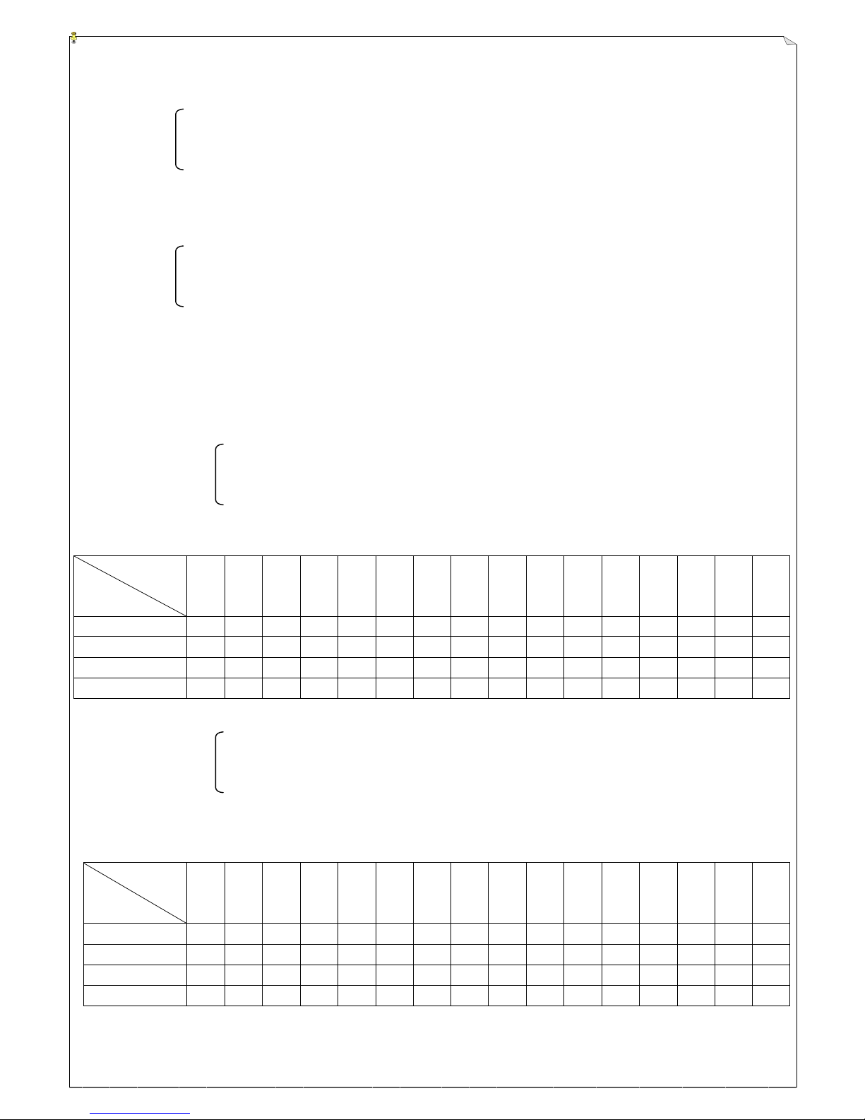
Bit or: The LID setting within 1~16 stages will replace the original LID of ID. Please
refer to below for the “bit or” comparison table. ”ˇ” means accept.
LID received
AUTOSCAN
LID setting
0000
0001
0010
0011
0100
0101
0110
0111
1000
1001
1010
1011
1100
1101
1110
1111
0001
ˇ ˇ ˇ ˇ ˇ ˇ ˇ
ˇ
0010
ˇ
ˇ
ˇ
ˇ
ˇ
ˇ
ˇ
ˇ
0100
ˇ ˇ ˇ
ˇ
ˇ ˇ ˇ
ˇ
1000
ˇ ˇ ˇ ˇ ˇ ˇ ˇ
ˇ
◎ EID Disable: Not in use
Bit match: In addition to 20bit ID, all the 1~16 EID setting and the EID received have
to match.
Bit or: In addition to 20bit ID, all the 1~16 EID setting and the EID received, the “EID
bit or” also has to match. Please refer to below for the “EID bit or”
comparison table. ”ˇ” means accept.
EID received
AUTOSCAN
EID setting
0000
0001
0010
0011
0100
0101
0110
0111
1000
1001
1010
1011
1100
1101
1110
1111
0001
ˇ ˇ ˇ ˇ ˇ ˇ ˇ ˇ 0010
ˇ
ˇ
ˇ
ˇ
ˇ
ˇ
ˇ
ˇ
0100
ˇ ˇ ˇ
ˇ
ˇ ˇ ˇ
ˇ
1000
ˇ ˇ ˇ ˇ ˇ ˇ ˇ
ˇ
* The assigned pushbutton enter AUTOSCAN function: When MAIN relay is ON, the transmitter will pass its
Page 33
33
operation priority to the other one.
Setting request: Transmitter 1 is set as channel 1 and transmitter 2 is set as channel 2. AUTOSCAN
enable is set as 2 stages. 1st stage is set as the channel for transmitter 1 and 2nd stage is set as the channel
for transmitter 2. Select one single speed pushbutton and set as ”assigned pushbutton enter AUTOSCAN
function”. Except for different channels, setting for transmitter 1 & 2 has to be completely identical.
Enable method: When the original transmitter in operation, receiver MAIN relay is ON, joystick or
neutral VR back to neutral position and single side VR back to 0° position, press down the assigned
pushbutton, then the receiver enters AUTOSCAN status and searches for the other transmitter. The
other transmitter has to START and standby, but no assigned pushbutton is pressed. After receiver
successfully catches the other transmitter, the AUTOSCAN function will stop and the operation priority is
transferred.
* Receiver relay setting
◎ LV relay: Transmitter low voltage relay or AUTOSCAN channel lock instruction
Function ON: Transmitter low voltage, LV relay ON
ON 2sec & OFF 2sec repeatedly: Transmitter low voltage, LV relay ON 2sec & OFF
2sec repeatedly
ON 1sec & OFF 1sec repeatedly: Transmitter low voltage, LV relay ON 2sec & OFF
2sec repeatedly
Shutoff Transmitter battery change or transmitter shutoff: Transmitter shutoff or change
fully charged battery.
(Not suitable for receiver channel AUTOSCAN enable)
Transmitter battery change: Transmitter should change the fully charged battery.
◎ STOP relay: Emergency stop relay
RELAY ON: Press emergency stop button when MAIN relay is ON. Or, receiver is
started but transmitter emergency stop button is pressed.
RELAY OFF: To activate emergency relay, transmitter non-emergency code has to be
received and receiver startup request has also to be met, that is, MAIN relay is activated.
◎ ID relay: Identical to MAIN relay ON/OFF.
◎ START relay: Press START button on transmitter, START relay ON; release START button then
START relay OFF
◎ ALARM relay MAIN relay ON Not in use.
ON 1~3sec: When MAIN relay ON, ALARM relay ON 1~3sec
MAIN relay OFF Not in use.
ON 1~3sec: When MAIN RELAY OFF, ALARM relay ON
1~3sec
* RELAY K1~K32 output position exchange: Corresponding function for relay K1~K32 is exchangeable at will.
Case 1: Each relay module is available with DC output relay up to 8pcs. (The change of AC output relay is
Page 34
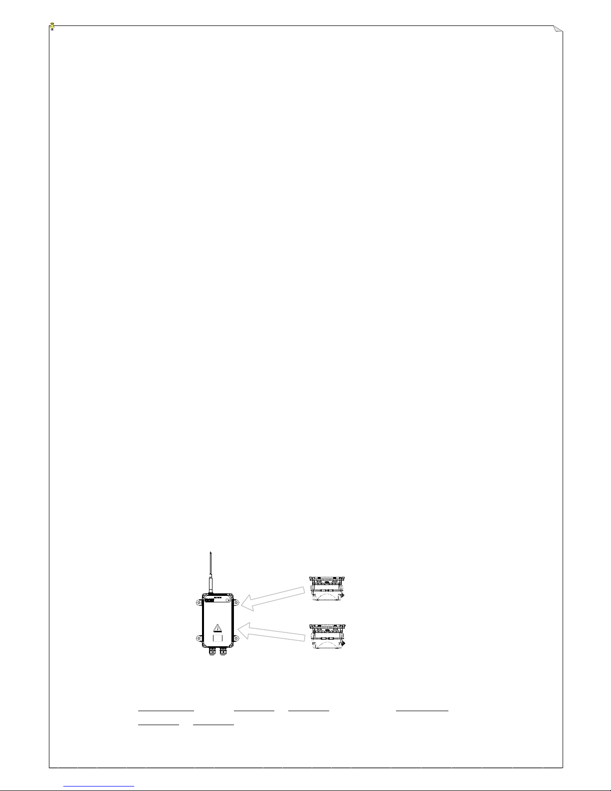
34
available upon request) That is each DC voltage output module is available with 8pcs of DC voltage
relay output. Whenever two types of voltage output, including relay and DC voltage output, are
mix distributed, relay K1~K32 may be applied to exchange output position. Arranging relay output
to relay module and DC voltage output voltage to AC voltage output module.
For example: 14-relay output and 7 DC voltage output are needed.
If you apply relay K1~K32 output position to exchange functions, the 14 relays will be
arranged from K1 toK14. Each receiver relay module, including slot I and II, with one relay
module. Keep K15 & K16 empty and then arrange 7 DC voltage output from K17 to K23.
Insert DC voltage output module to receiver relay module slot III.
Case 2: After the wiring for receiver relay output is completed, if more or less function is needed, relay
number and sequence will have to be changed and the re-wiring is needed. Relay K1~K32 output
can be applied to exchange function. For increasing relay numbers, the new wiring sequence can
be re-arranged manually to match the original wiring arrangement. Then move the increasing
relays to the last position in sequence, so that only the increased relay contacts need to be wired, the
original wiring will remain unchanged. For decreasing relay numbers, the new wiring sequence can
be re-arranged manually to match the original wiring arrangement. Then keep the decreasing relay
positions empty, so the original wiring will remain unchanged.
4.4 Special Types:
* “Pitch and Catch” Feature/Assigned button AUTOSCAN as below:
(1) Two transmitters (or more) take turn to control one receiver.
(2) Move the transmitter joystick and VR in operation back to neutral position and depress
assigned pushbutton for 0~3 seconds (by following “enter auto-scan channel delay time”).
(3) After the assigned pushbutton signal is received by the receiver, the receiver will look for
the transmitter which is going to take turn by AUTOSCAN.
(4) Press START button on the transmitter that catches the signal for 0~3 seconds (No assigned
pushbutton is pressed. Please follow “time for salve channel lock” setting).
(5) After the receiver has scanned and caught the transmitter that takes over, the AUTOSCAN
control will also be taken over by the transmitter that takes over.
(6) Please turn off the original transmitter in operation.
* One Transmitter to Two Receivers Feature (Tandem Mode): two operation types
(1) Transmitter 1 operates receiver 1 or receiver 2 independently; transmitter 2 operates
receiver 1 or receiver 2 independently.
Alpha 6000
Receiver
Alpha 6000
Transmitter
Alpha 6000
Transmitter
Page 35
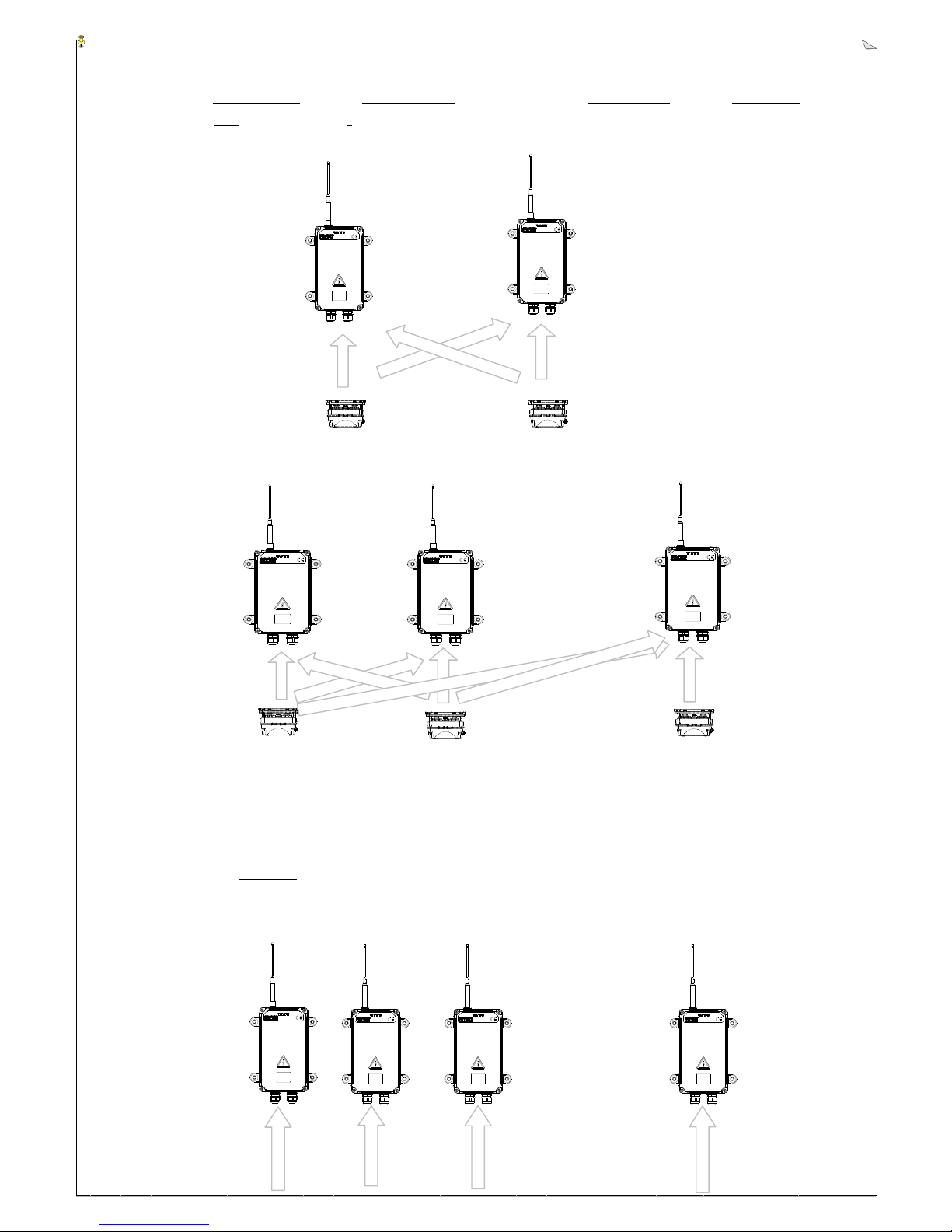
35
Alpha 6000
Transmitter 2
Alpha 6000
Transmitter 1
Alpha 6000
Transmitter 8
(2) Transmitter 1 operates receiver 1 & 2 at the same time, or transmitter 2 operates receiver 1
& 2 at the same time.
* The transmitter that controls the receiver gets the control priority.
(3) Maximum up to 1 transmitter to 8 receivers (Tandem mode)
* Random Access Feature:
(1) This feature allows for up to 8 operators randomly accessing up to 8 crane systems.
(2) 8 receivers with respective channels.
(3) The channel changes can be done via a multi-position selector switch on each transmitter.
* Do not control one receiver with two or more than two transmitters at the same time.
Alpha 6000
Transmitter 2
Alpha 6000
Transmitter 1
Alpha 6000
Receiver 1
Alpha 6000
Receiver 2
Alpha 6000
Receiver 1
Alpha 6000
Receiver 2
Alpha 6000
Receiver 3
Alpha 6000
Receiver 8
Alpha 6000
Receiver 1
Alpha 6000
Receiver 2
Alpha 6000
Receiver 8
…………..
…………..
Page 36
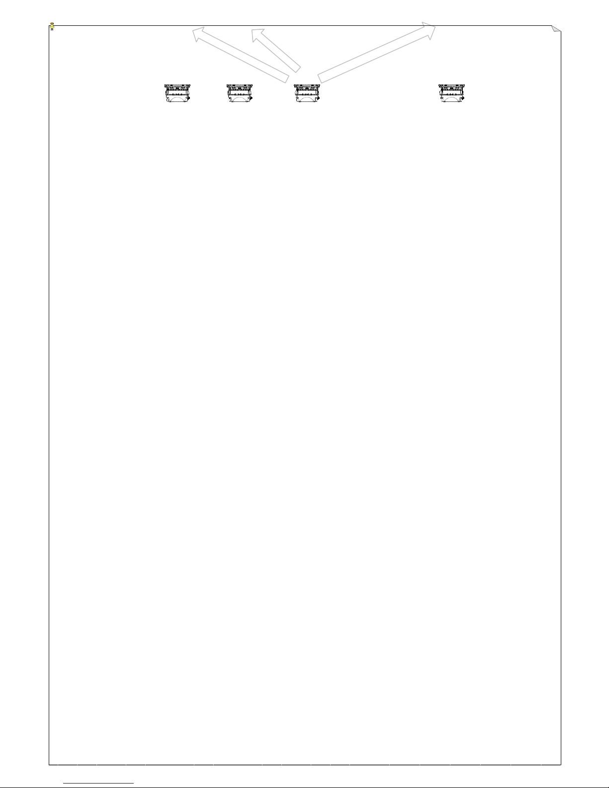
36
4.5 Customized Types
There are many types of customized system available with the combination of single-axis joystick,
double-axis joystick, pushbuttons and switches for the Alpha 6000. Please talk to the manufacturer
for more information.
Alpha 6000
Transmitter 1
Alpha 6000
Transmitter 2
Alpha 6000
Transmitter 3
Alpha 6000
Transmitter 8
Page 37
37
4.6 Frequency Table
CHANNEL
433MHz/25k
CHANNEL
447MHz/12.5k
401
433.0750 MHz
701
447.8750 MHz
402
433.1000 MHz
702
447.8875 MHz
403
433.1250 MHz
703
447.9000 MHz
404
433.1500 MHz
704
447.9125 MHz
405
433.1750 MHz
705
447.9250 MHz
406
433.2000 MHz
706
447.9375 MHz
407
433.2250 MHz
707
447.9500 MHz
408
433.2500 MHz
708
447.9625 MHz
409
433.2750 MHz
709
447.9750 MHz
410
433.3000 MHz
710
447.9875 MHz
411
433.8250 MHz
711
448.0000 MHz
412
433.8500 MHz
712
448.0125 MHz
413
433.8750 MHz
713
448.0250 MHz
414
433.9000 MHz
714
448.0375 MHz
415
433.9250 MHz
715
448.0500 MHz
416
433.9500 MHz
716
448.0625 MHz
417
433.9750 MHz
717
448.0750 MHz
418
434.0000 MHz
718
448.0875 MHz
419
434.0250 MHz
719
448.1000 MHz
420
434.0500 MHz
720
448.1125 MHz
421
434.0750 MHz
721
448.1250 MHz
422
434.1000 MHz
722
448.1375 MHz
423
434.1250 MHz
723
448.1500 MHz
424
434.1500 MHz
724
448.1625 MHz
425
434.1750 MHz
725
448.1750 MHz
426
434.2000 MHz
726
448.1875 MHz
427
434.2250 MHz
727
448.2000 MHz
428
434.2500 MHz
728
448.2125 MHz
429
434.2750 MHz
729
448.2250 MHz
430
434.3000 MHz
730
448.2375 MHz
431
434.3250 MHz
731
448.2500 MHz
432
434.3500 MHz
732
448.2625 MHz
433
434.3750 MHz
733
448.2750 MHz
434
434.4000 MHz
734
448.2875 MHz
435
434.4250 MHz
735
448.3000 MHz
436
434.4500 MHz
736
448.3125 MHz
437
434.4750 MHz
737
448.3250 MHz
438
434.5000 MHz
738
448.3375 MHz
439
434.5250 MHz
739
448.3500 MHz
Page 38
38
440
434.5500 MHz
740
448.3625 MHz
441
434.5750 MHz
741
448.3750 MHz
442
434.6000 MHz
742
448.3875 MHz
443
434.6250 MHz
743
448.4000 MHz
444
434.6500 MHz
744
448.4125 MHz
445
434.6750 MHz
745
448.4250 MHz
446
434.7000 MHz
746
448.4375 MHz
447
434.7250 MHz
747
448.4500 MHz
448
434.7500 MHz
748
448.4625 MHz
449
434.7750 MHz
749
448.4750 MHz
450
433.3250 MHz
750
448.4875 MHz
451
433.3500 MHz
751
448.5000 MHz
452
433.3750 MHz
752
448.5125 MHz
453
433.4000 MHz
753
448.5250 MHz
454
433.4250 MHz
754
448.5375 MHz
455
433.4500 MHz
755
448.5500 MHz
456
433.4750 MHz
756
448.5625 MHz
457
433.5000 MHz
757
448.5750 MHz
458
433.5250 MHz
758
448.5875 MHz
459
433.5500 MHz
759
448.6000 MHz
460
433.5750 MHz
760
448.6125 MHz
461
433.6000 MHz
761
448.6250 MHz
462
433.6250 MHz
762
448.6375 MHz
463
433.6500 MHz
763
448.6500 MHz
464
433.6750 MHz
764
448.6625 MHz
465
433.7000 MHz
765
448.6750 MHz
466
433.7250 MHz
766
448.6875 MHz
467
433.7500 MHz
767
448.7000 MHz
468
433.7750 MHz
768
448.7125 MHz
Page 39
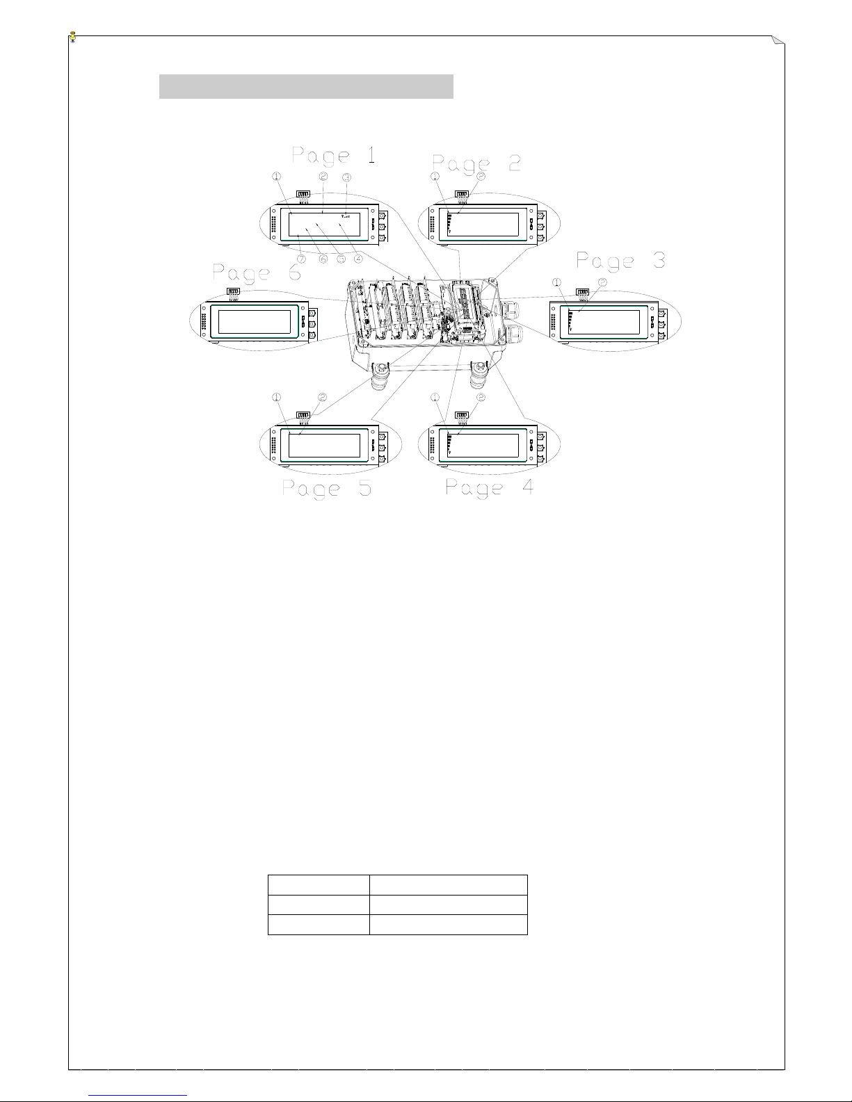
39
J1 : +04 . 4V J2 : +05 . 0V
J3 : 1 STEP J4 : 2 STEP
J5 : 0 STEP J6 : 0 STEP
J7 : 0 STEP J8 : 0 STEP
α6000 CH:401
EI D: 00 00 I D : A600 0
MRly :O FF
Se ar ch . . . . .
P1 : -- - - -- - - -- 06 -- -P2 : -- 1011 -- - - -- -- -P3 :
P4 :
E1 : 01 - - -- 04 -- - - -E2 : 09 - - -- - - 14 - - -E3 : -- -- - - -E4 :
J1 : 0~ +5V J2 : 0~ +5V
J3 : 1STEP I J4 : 2STEP I
J5 : 1STEP E J6 : 2STEP E
J7 : 2STEPsE J8 : 5STEP E
Ty pe : α 6000
De co de r v er :0 0. 06
Se ri al :0 00 00 00 0
Mf g. Da te :0 00 0/ 00 /0 0
(Fig. 15) Receiver LCD Displays
5.
SYSTEM SETTINGS
5.1 Receiver LCD Function Settings
5.2 LCD Display Descriptions:
Pushbutton 1 page change: Page 1 → Page 2 → Page 3 → Page 4 → Page 5 → Page 6 →
Page 1 → ………
Pushbutton 2 page change: Page 1 → Page 6 → Page 5 → Page 4 →Page 3 → Page 2 →
Page 1 → ………
Pushbutton 3: Reserved.
1) When the receiver power is ON, the initial display on LCD is “α6000 decoder loading.....”.
2) When internal interface is connected correctly, the first LCD display would be “page1”.
Line 1:
① α6000 System Type
② CH: 401 1st code is frequency band code, the 2nd and 3rd is for channel 01~68.
BAND CODE
FREQUENCY BAND
4
433 MHz
7
447 MHz
③ 〒▁▃▄▆█ Signal strength, 5 sections in total. Full 5-section is for the strongest
signal and empty 5-section is for the weakest signal.
Page 40
40
Line 2:
○
4
EID:0000 4 bits (4 bits/binary), after AUTOSCAN EID function enable.
For receiver ID comparison.
○
5
ID:12345 ID for receiver comparison, 5 bits (20 bits/ Hexadecimal)
Line 3:
⑥ MRly OFF MAIN relay deactivated
MRly ON MAIN relay activated
Line 4: Message
⑦ Search….. Searching transmitter ID
Scan>>>>>> AUTO channel searching
Work>>>>>> Functioning
Error Message
Description
Error:Eeprom ack
Decoder EEPROM read-out/write-in error
Error:Eeprom id
Decoder EEPROM ID setting error
Error:Eeprom crc
Decoder EEPROM data CRC error
Error:Relay > 32pcs
Decoder relay setting over 32pcs
Error:Rf usart
Decoder to RX module interface faulty
Error:Rf module
RX module faulty
Error:Com or 2803
Decoder relay power faulty
Error:Main relay
Decoder MAIN relay faulty
Error:V&I card
Error:PWM card
Error on PWM proportional output interface card
Error:Watchdog
Faulty on watch-dog layout of decoder externals
Receiver voltage low
Decoder voltage is too low <10VDC
ID not match
Receiver with un-identical ID
Emergency Stop
Decoder receives stop command
Error:Main1 LOOP
OUT
Main relay 1 control module faulty, LOOP OUT
Error:Main2 LOOP
OUT
Main relay 2 control module faulty, LOOP OUT
Error:Main1 CAN
LOSS
Main relay 1 control module faulty, CANBUS LOSS
Error:Main2 CAN
LOSS
Main relay 2 control module faulty, CANBUS LOSS
Error:Main1 RF
LOSS
Main relay 1 control module faulty, receiving RF module misses
the signal
Error:Main2 RF
LOSS
Main relay 2 control module faulty, receiving RF module misses
the signal
Error:Main1 STOP
Main relay 1 control module faulty, STOP
Error:Main2 STOP
Main relay 2 control module faulty, STOP
Error:Main1 pre-on
Main relay 1 control module faulty, Pre-START overtime
Error:Main2 pre-on
Main relay 2 control module faulty, Pre-START overtime
Page 41

41
3) Page 2: joystick/VR function display
① Signal strength, 5 sections in total. Full 5-section is for the strongest signal, empty
5-section is for the weakest signal.
② Joystick or VR output
Line 1: J1:+10.0V J2:24.0mA
J1 is for joystick 1 or VR1 output; J2 is for joystick 2 or VR2 output
Line 2: J3:-10.0V J4:00.0mA
J3 is for joystick 3 or VR3 output; J4 is for joystick 4 or VR4 output
Line 3: J5:0 STEP J6:5 STEP
J5 is for joystick 5 or VR5 output; J6 is for joystick 6 or VR6 output
Line 4: J7:NO USE J8:NO USE
J7 is for joystick 7 or VR7 output; J8 is for joystick 8 or VR8 output
Remark: Joystick, VR proportional voltage or current output is displayed as “calculated value”, not “measured
value”(*) from output terminal. (0~+5V、0~±5V、0~+10V、0~±10V、4~20mA、0~20mA & 0~24mA. The
approximate difference between LCD display value and output value is ±0.2)
4) Page 3: Relay function display
① Signal strength, 5 sections in total. Full 5-section is for the strongest signal and empty
5-section is for the weakest signal.
② Relay output
Line 1: P1: 01 02 03 -- -- -- -- 08
P1 is to relay module card I. P1: In sequence to relay K01 ~ K08.
“01” is K01 RELAY ON, “--" is K01 RELAY OFF, “ ”(empty) is K01 RELAY not in use.
: : :
: : :
“08” is K08 RELAY ON,“--" is K08 RELAY OFF, “ “(empty) is K08 RELAY not in use.
Line 2: P2: 09 -- -- -- -- -- -- 16
P2 is to relay module card II. P2: In sequence to relay K09 ~ K016
“09” is K01 RELAY ON, “--" is K09 RELAY OFF, “ ”(empty) is K09 RELAY not in use.
: : :
: : :
“16” is K16 RELAY ON,“--" is K16 RELAY OFF, “ “(empty) is K16 RELAY not in use.
Line 3: P3: 17 -- -- -- -- -- -- 24
P3 is to relay module card III. P3: In sequence to relay K17 ~ K24
“17” is K17 RELAY ON, “--" is K17 RELAY OFF, “ ”(empty) is K17 RELAY not in use.
: : :
: : :
“24” is K24 RELAY ON,“--" is K24 RELAY OFF, “ “(empty) is K24 RELAY not in use.
Page 42

42
Line 4: P4: 25 -- -- -- -- -- -- 32
P4 is to relay module card IV. P4: In sequence to relay K25 ~ K32
“25” is K25 RELAY ON, “--" is K25 RELAY OFF, “ ”(empty) is K25 RELAY not in use.
: : :
: : :
“32” is K32 RELAY ON,“--" is K32 RELAY OFF, “ “(empty) is K32 RELAY not in use.
5) Page 4: External extension relay function display
① Signal strength, 5 sections in total. Full 5-section is for the strongest signal and empty
5-section is for the weakest signal.
② External extension relay output
Line 1: E1: 01 02 03 -- -- -- -- 08
E1 is in the CN7 slot of external extension system, relay module card I.
E1: In sequence to external relay K01 ~ K08
“01” is external K01 RELAY ON, ”--" is external K01 RELAY OFF, ” “ (empty) is
external K01 RELAY not in use
: : :
: :
“08” is external K08 RELAY ON, ”--" is external K08 RELAY OFF, ” “ (empty) is
external K08 RELAY not in use
Line 2: E2: 09 -- -- -- -- -- -- 16
E2 is in the CN8 slot of external extension system, relay module card II.
E2: In sequence to external relay K09 ~ K16
“09” is external K09 RELAY ON, ”--" is external K09 RELAY OFF, ” “ (empty) is
external K09 RELAY not in use
: : :
: :
“16” is external K16 RELAY ON, ”--" is external K16 RELAY OFF, ” “ (empty) is
external K16 RELAY not in use
Line 3: E3: 17 -- -- -- -- -- -- 24
E3 is in the CN9 slot of external extension system, relay module card III.
E3: In sequence to external relay K17 ~ K24
“17” is external K17 RELAY ON, ”--" is external K17 RELAY OFF, ” “ (empty) is
external K17 RELAY not in use
: : :
: :
Page 43
43
“24” is external K24 RELAY ON, ”--" is external K24 RELAY OFF, ” “ (empty) is
external K24 RELAY not in use
Line 4: E4: 25 -- -- -- -- -- -- 32
E4 is in the CN10 slot of external extension system, relay module card IV.
E1: In sequence to external relay K25 ~ K32
“25” is external K25 RELAY ON, ”--" is external K25 RELAY OFF, ” “ (empty) is
external K25 RELAY not in use
: : :
: :
“32” is external K32 RELAY ON, ”--" is external K32 RELAY OFF, ” “ (empty) is
external K32 RELAY not in use
6) Page 5: Joystick/VR setting display
Line 1: J1:+-10V J2:0~24mA
J1: joystick 1 or VR1 output setting; J2: joystick 2 or VR2 output setting
Line 2: J3:+-10V J4:0~24mA
J3: joystick 3 or VR3 output setting; J4: joystick 4 or VR4 output setting
Line 3: J5:5STEP I J6:5STEP I
J5: joystick 5 or VR5 output setting; J6: joystick 6 or VR6 output setting
Line 4: J7: Not in use; J8: Not in use.
J7: joystick 7 or VR7 output setting; J8: joystick 8 or VR8 output setting
DISPLAY
OUTPUT SETTING
NO USE
Not in use
0~+5v
0~+5V
0~+10v
0~+10V
+-5v
0~±5v
+-10v
0~±10v
4~20mA
4~20mA
0~20mA
0~20mA
0~24mA
0~24mA
OPTIONAL
OPTIONAL
1STEP I
Single speed joystick.
2STEP I
Double-speed joystick, not to share the 2-speed relay.
2STEPs I
Double-speed joystick, not to share the 2-speed relay. 1 & 2speed relay do not activate at the same time.
3STEP I
3-speed joystick, share the 2-speed and above relay.
4STEP I
4-speed joystick, share the 2-speed and above relay.
5STEP I
5-speed joystick, share the 2-speed and above relay.
1STEP E
External extension single-speed joystick
Page 44
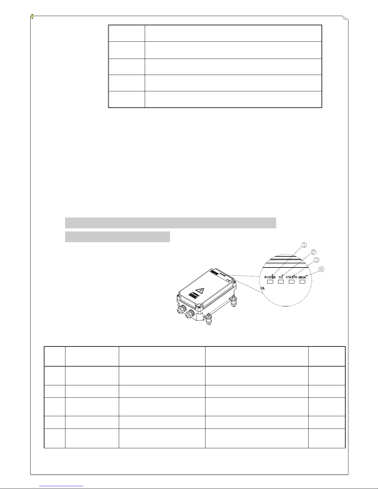
44
(Fig. 16) Receiver Status Light
2STEP E
External extension double-speed joystick, not to share the 2-speed
relay
2STEPs E
External extension double-speed joystick, not to share the 2-speed
relay. 1 & 2-speed relay do not activate at the same time.
3STEP E
External extension three-speed joystick, share the 2-speed and
above relay..
4STEP E
External extension four-speed joystick, share the 2-speed and
above relay..
5STEP E
External extension five-speed joystick, share the 2-speed and
above relay.
7) Page 6: Message
Line 1: Type:α6000
Line 2: Decoder ver:00.06
Decoder MCU firmware version
Line 3: Serial:00000001
Serial number
Line 4: Mfg.Date:2013/1/23
Manufacturing date
6. RECEIVER STATUS LIGHT AND
INSTALLATION
6.1 Receiver Status Light
1. Power LED Display
2. Signal LED Display
3. Status LED Display
4. MAIN relay LED Display
6.2 Receiver LED Status
ITEM
CONDITION
REASON
STATUS LED DISPLAY
REMARK
1
Power ON, voltage
abnormal
Voltage > 15V or voltage < 10.5
Red LED ON_0.1/OFF_0.1
All output off
2
High Voltage
Voltage > 16V
Red LED ON, green LED ON
3
System START
error display
External watchdog abnormal
Red LED ON_0.1/OFF_0.3sec with 8
blinks, OFF_0.8sec
All output off
4
Low Voltage
Voltage <10V
Red LED OFF, green LED OFF
All output off
5
EEPROM invalid
EEPROM data write-in failed or
data error. (ID, CRC, …)
Red LED ON_0.1/OFF_0.3sec with 7
blinks, OFF_0.8sec
All output off
Page 45
45
6
RELAY setting
error
Internal RELAY > 32PCS
Red LED ON_0.1/OFF_0.3sec with 5
blinks, OFF_0.8sec
All output off
7
START system
display error
COM or 2803 feedback check
abnormal
Red LED ON_0.1/OFF_0.3sec with 8
blinks, OFF_0.8sec
All output off
8
RX module invalid
TX module faulty is detected by
decoder
Red LED ON_0.1/OFF_0.3sec with 4
blinks, OFF_0.8sec
All output off
9
MAIN RELAY
jammed
MAIN relay check NG
Red LED ON_0.1/OFF_0.3sec with 3
blinks, OFF_0.8sec
All output off
10
Faulty on interface
connection
Faulty on voltage, current,
proportional output interface
card, PWM proportional output
interface card or outer extension
relay module
Red LED ON_0.1/OFF_0.3sec with 6
blinks, OFF_0.8sec
All output off
11
ID error
ID error
Red LED ON_0.1/OFF_0.3sec with 2
blinks, OFF_0.8sec
Standby
status
12
Delay on
AUTOSCAN slave
channel locking
AUTOSCAN slave CH lock
delay
Green LED ON
Standby
status
13
Abnormal
STARTUP status
MAIN RELAY is not activated.
START and emergency stop
commands are sending at the
same time.
Red LED ON_0.1sec, green LED
ON_0.1sec blink
Standby
status
14
Function normally
MAIN RELAY is activated,
ID is correct & SQ light has to
be ON
Whenever correct transmitter ID code
is received, Green LED ON_0.05sec
Standby
status
15
STANDBY
(working but
without receiving
signal)
DATA shown as noise or DC
Green LED ON_0.1sec, OFF_0.8sec
blink
Standby
status
MAIN Relay module board
ITEM
CONDITION
REASON
GREEN STATUS LED DISPLAY
1
Connection failure
CAN BUS receiving
error
No light displayed
2
Decoder board status
error
Decoder status error
Green LED continuous ON
3
Normal operation
Normal operation
ON_0.1sec, OFF_0.1sec blink
Page 46
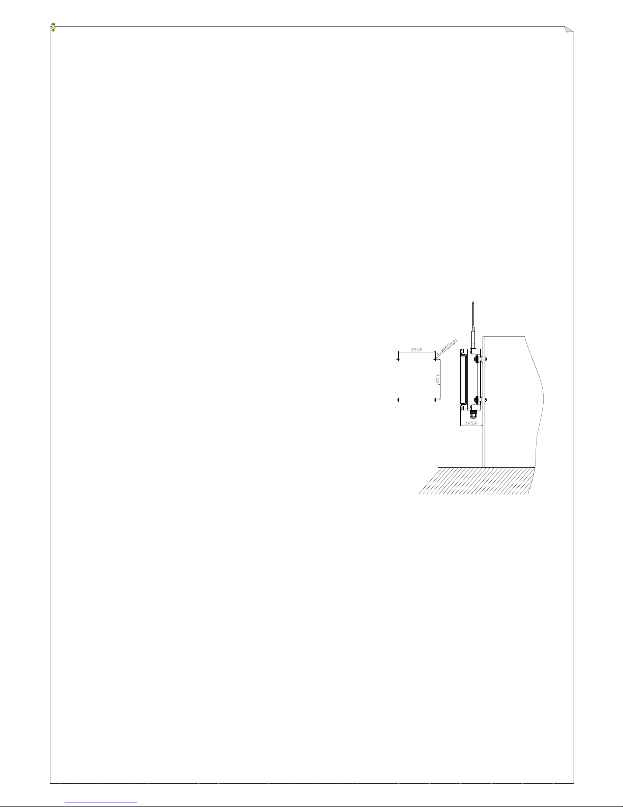
46
(Fig. 17) Receiver Installation
6.3 Preparation
1. Required Tools:
(1) Flat Head Screwdriver (-)
(6) Self Drill φ10.5 mm ~φ11 mm
(2) 5 mm Wrench
(7) Needle-nose pliers
(3) Multi-Meters
(8) Diagonal pliers
(4) 14 mm Box Wrench or Socket Wrench
(9) Wiring Cable(cord between 14 mm ~18 mm) and
Materials
(5) Power Drill with 10.5~11mm Drill-Bit
2. Ensure receiver is not set to the same frequency channel and ID code as any other units in
use at the same facility or within distance of 300 meters.
3. Prior to installation, make sure that the crane system itself is working properly.
4. Use the multi-meter to check the voltage source available and ensure receiver voltage
setting is correct for this voltage.
5. Prior to installation, switch off the main power source to the
equipment.
6.4 Steps-By-Steps Installation
1. Be sure to put a stopper in the cable gland not in use after
wiring is completed.
2. Select a suitable location that is far from high voltage wiring or
equipment, such as motor, relay…etc., to mount the receiver.
3. As much as possible, the location selected should have the
antenna visible from all areas where the transmitter is to be
used.
4. The location selected should not be exposed to high levels
of electrical noise.
5. Ensure the selected location has adequate space to accommodate the receiver enclosure.
6. The distance between the antenna and the control panel should be as far apart as possible.
7. The use of an external axial cable to move the receiving antenna to the position for better signal
receipt where it is necessary.
8. Drill four holes on the control panel (11mm).
9. Tightened all screws provided.
10. For system wiring, please refer to the wiring diagram located on the last page of this manual and
on the backside of the receiver cover plate.
11. Ensure all wiring is correct and safely secured and all screws are fastened.
12. The power cable has to be connected to the AC position of power terminal block; the
ground wire has to be connected to the GND position (crane metal frame) or to the screw
fixing hole of ground wire on the receiver.
Page 47
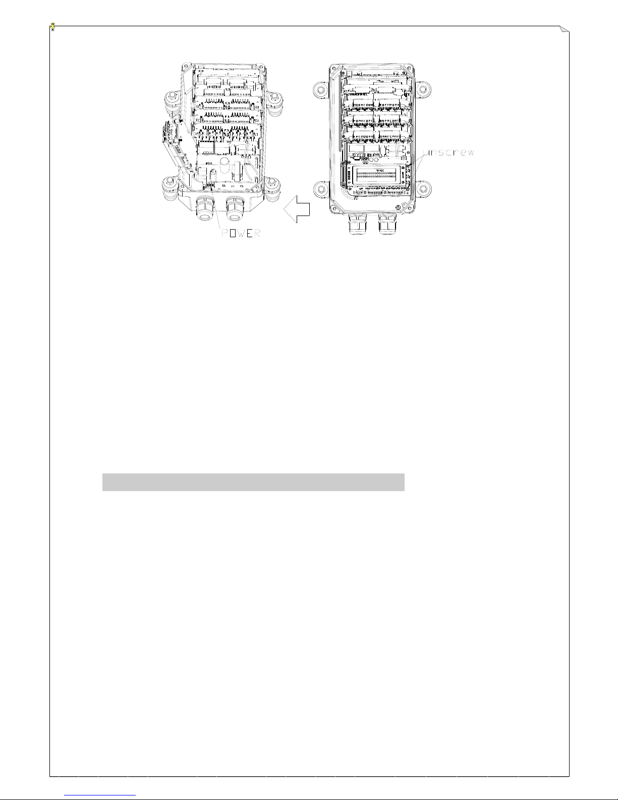
47
(Fig. 18)
13. Please refer to below figures. To open the metal cover, unscrew the power module cover as
positioned.
6.5 Wiring Diagram
Please refer to the wiring diagram located on the last page of this manual and on the backside of
the receiver cover plate.
6.6 System Testing
1. Connect the power source to the receiver and test the operation of each function to
ensure it operates in the same manner as the pendant controller.
2. Ensure the MAIN contact relay can be properly controlled by the remote control.
3. Ensure the limit switches on the crane that limit all travels are working properly.
4. Ensure the pendant controller is located in a safe location where it would not interfere
with remote operation.
7. OPERATING INSTRUCTION
7.1 Power “ON” the System
1. Insert the transmitter power key into the key-switch slot located on the right side of the transmitter
belly box.
2. Push the transmitter power key inward and then rotate it clockwise to “1” position.
“1” → “ON” “0” → “OFF”
3. To activate the system, first turn the EMS button clockwise so that the red button pops up. To
activate the function “When transmitter power is turned on, emergency stop button is compelled to
press & release check”: Press emergency stop button and release.
4. Press the START pushbutton to activate MAIN relay and the transmitter starts to send signals.
5. After 5 minutes of inactivity, that is 5 minutes after the last pushbutton is released, the green light
Page 48
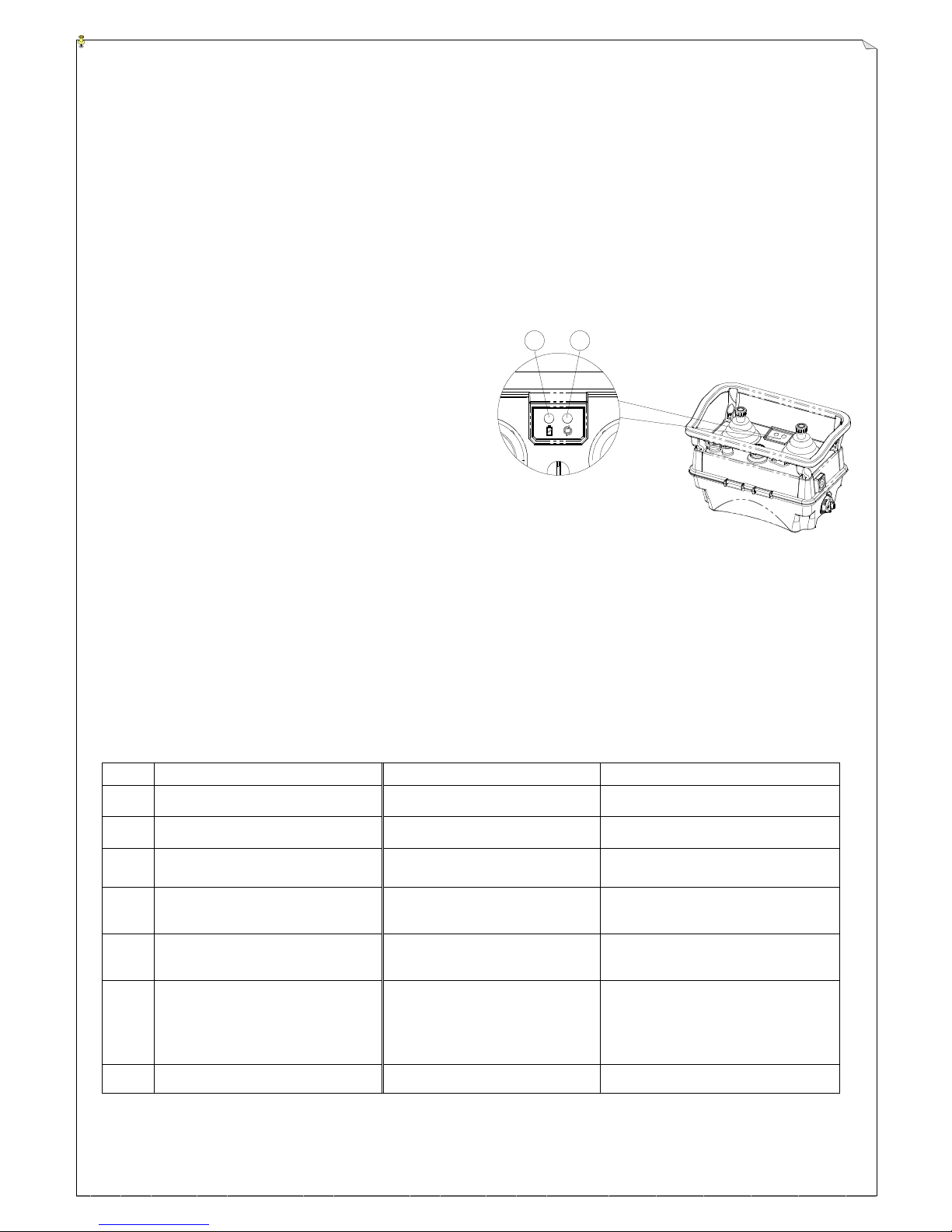
48
1 2
will disappear thus temporarily deactivating the transmitter power and the receiver MAIN.
Pressing START pushbutton thereafter will close the receiver MAIN and start the timing sequence
over again.
6. If any function, such as the frequency channel of the transmitter unit is altered via simple dip-switch
setting inside the transmitter (refer to page 13), you must then also change the frequency RF channel
in the receiver (refer to page 15~16). If the “auto-scanning feature” on the receiver is activated,
you must then press and hold the START pushbutton after turning “on” the transmitter power in
order for the auto-scanning receiver to identify the newly selected channel and then you may release
the START pushbutton to operate.
7.2 Transmitter System Status Displays
7.2.1 Transmitter LED Display
(Fig.19) Transmitter LED Display
(1) Battery Power LED Display:High power green LED on; Low power red LED on.
(2) Transmitter Status LED Display: Normal status green LED on; Abnormal status red LED on.
7.2.2 Transmitter LED Status Table
Encoder-Power Status LED Display (dual colors)
ITEM
STATUS
CONDITION
LED STATUS
1
Low voltage power on
Full current, power < 6.0V
Red LED steady ON
2
Low voltage during operation (3)
Power < 5.1V
Red LED constant ON
3
Low voltage during operation (2)
Power > 5.1V < 5.5V
Red LED ON_0.1.OFF_0.1sec
until power_off
4
Low voltage during operation (1)
Power > 5.5V < 6.0V
Red LED ON_0.1.OFF_0.9sec
until power off
5
Joystick correction mode
Enter joystick correction
Orange LED ON (red and green
LED steady ON)
6
Emergency stop button is not
pressed
Checking the press & release
function of emergency stop
button when emergency stop
button is not pressed.
Green ON_0.1sec, OFF_0.9sec
blink
7
Normal operation
Power > 6.0V
Green LED ON
Page 49
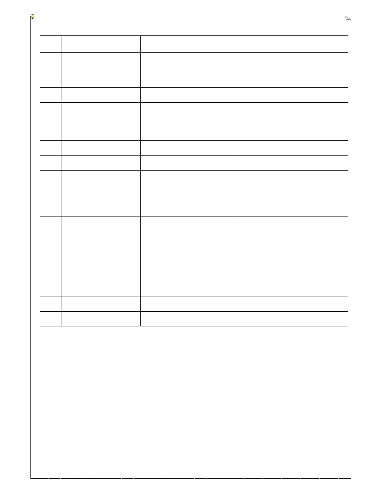
49
Encoder-Status LED Display (dual colors)
ITEM
STATUS
CONDITION
LED STATUS
1
Low mid-voltage
Power < 6.0V
All LED status lights off
2
System error
Failed on external Watchdog wiring
check or ADC reference voltage
error
Red LED ON_0.1/OFF_0.3sec with 8
blinks, OFF_0.8sec
3
Check pushbuttons, increase
resistance value
Pushbutton and increase resistance
value error
Red LED ON_0.1/OFF_0.3sec with 6
blinks,OFF_0.8sec
4
EEPROM error
EEPROM data read out / write in
error or data error (ID, CRC, …)
Red LED ON_0.1/OFF_0.3sec with 7
blinks,OFF_0.8sec
5
Pushbutton jammed or
joystick is not in the neutral
position
Power ON when some of the
pushbuttons are activated
Red LED ON_0.1/OFF_0.3sec with 2
blinks,OFF_0.8sec
6
Joystick correction has
never been proceeded
Joystick correction has to be done
to those joysticks with settings
Red LED ON_0.1/OFF_0.3sec with 3
blinks,OFF_0.8sec
7
Joystick correction error
Joystick correction over time or
step incorrect.
Red LED ON_0.1/OFF_0.3sec with 5
blinks,OFF_0.8sec
8
Joystick correction
completed
Enter joystick correction completed
Orange (red + green) LED
ON_0.5sec/OFF_0.5sec blink
9
TX module invalid
TX module error is detected by the
encoder
Red LED ON_0.1/OFF_0.3sec with 4
blinks,OFF_0.8sec
10
Drop or tilt protection
Protection to the transmitter which
is dropped or tilt.
Red LED ON_0.2/OFF_0.2sec blink
11
Re-awake status after sleep
mode: pushbutton jammed or
joystick is not in the neutral
position
Re-awake after sleep mode: depress
START button, joystick is not in the
neutral position or pushbutton
jammed
Red LED ON_0.05/OFF_0.05sec blink
12
STOP button is not pressed
During e-stop button press /
release check, e-stop button is not
pressed
All status lights off
13
Enter STOP
Press emergency stop button
All status LEDs are OFF
14
Normal power_on
Normal voltage and some of the
pushbuttons are not pressed
Green LED ON 2sec and OFF
15
Transmitter in operation
TX board signal intermittent or
continue to send signals
Green LED ON_0.1sec, OFF_0.1sec
blink
16
Transmitter standby
Without stopping or continue to
send signals
Green LED ON_0.1sec, OFF_0.9sec
blink
7.3 Joystick Correction
7.3.1 Reasons for Joystick Correction
The assembly / change of new joystick, increasing deviation after long-term operation or joystick output
non-proportional. (Not caused by settings)
7.3.2 Enter Joystick Correction Mode
Before joystick correction is proceeding, please first rotate transmitter power key to OFF position.
Dip-switch S2 on transmitter has to be set as 100000. (see below figure) After the setting of joystick
correction is done, rotate the power key to ON position. The power LED will display in orange (red and
Page 50
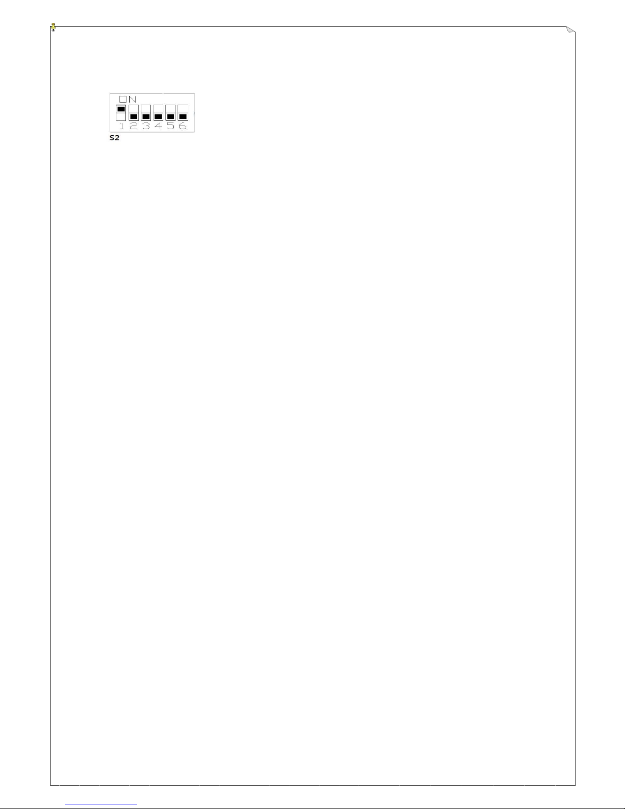
50
green lights are ON at the same time), and the status LED will display in green quick blinks then the
transmitter enters joystick correction mode.
7.3.3 Joystick Correction Steps
Proportional joystick:
1. Select either joystick and operate it slowly. Then the buzzer will beep once briefly which means the
joystick axis direction catches the start position.
2. Continue to operate the joystick swiftly to the end and hold. Then the buzzer will beep twice briefly
which means the joystick axis direction catches the end position. The directional axis correction is
now completed and joystick may back to neutral position.
3. Repeat step 1 & 2 to correct the reverse directional axis of the joystick.
4. Repeat step 1~3 to complete all joysticks correction. After the joystick correction is completed, the
buzzer will have a long beep once and then the joystick status LED blinks in orange slowly.
5. When status LED display becomes orange blinking slowly, then setting is completed. Please refer to
8.3.4 for exiting from correction mode.
Digital joystick 1~5 speeds:
1. Select either joystick, operate it to the 1st speed position and hold. Then press START button and the
buzzer will beep once briefly. Release START button and the joystick axis direction catches the 1st
speed position.
2. Locate the 2nd ~5th speeds directional axis by following step 1. Then operate the joystick back to the
neutral position after the correction is completed.
3. Repeat step 1 & 2 to correct the reverse directional axis of the joystick.
4. Repeat step 1~3 to complete all joysticks correction. After the joystick correction is completed, the
buzzer will have a long beep once and then the joystick status LED blinks in orange slowly.
5. When status LED display becomes orange blinking slowly, then setting is completed. Please refer to
8.3.4 for exiting from correction mode.
7.3.4 Exit
After all joystick correction is completed, rotate the transmitter power switch to OFF position and set
dip-switch S2 as 000000 as shown on below figure, then all joysticks exit the correction mode and back to
normal operation.
Page 51
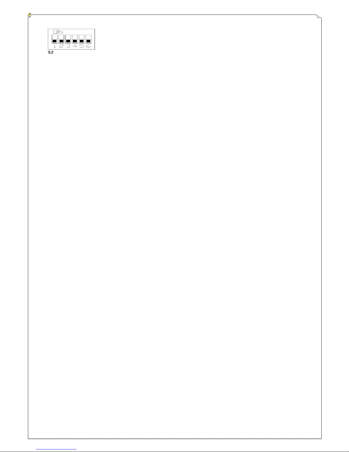
51
Note:
(1) Please do not proceed with joystick correction when voltage is low. When voltage is low, please rotate
power key switch to OFF position and replace battery.
(2) Joystick correction has to be proceeded by following joystick axis sequence, otherwise joystick correction
cannot be continued and status LED display will also show as orange fast blinking light. If transmitter is
available with both digital and proportional joysticks, please correct the joysticks by following correction
steps for digital and proportional joystick respectively.
(3) Under “Correction Standby” condition, if no joystick is operated for more than 30 seconds, buzzer for
joystick correction overtime will have one long beep for warning. Status LED display will also show as red
LED ON_0.1sec/OFF_0.3sec with 5 blinks and OFF_0.8sec, then correction will be discontinued. There is
no sequence request for joystick correction. After long as correction for all joysticks is completed, the
status LED will continue to blink slowly in orange.
(4) Under “Correction” condition, if the joystick axis is not changed for more than 30 seconds or if the joystick
is back to neutral position, buzzer for joystick correction overtime will have one long beep for warning.
Status LED display will also show as red LED ON_0.1sec/OFF_0.3sec with 5 blinks and OFF_0.8sec, then
correction will be discontinued. During joystick correction, if status LED blinks in red for 5 times (please
refer to “Encoder status LED display”) and there will have long beep on the buzzer, then the correction is
failed. In this case, please shutoff the power and start the correction again.
(5) Under “2nd step Correction” condition, only the maximum joystick axis value will be recorded. No timing
will be over 30 seconds. During the 2nd step correction, please operate the joystick forward smoothly. Do
not shake the joystick or operate the joystick backward, otherwise the joystick correction cannot be
completed. Under “Correction Mode condition”, the power status LED displays in orange and the
correction has to be completed in 3 minutes. If not, the status LED blinks in red for 5 times (please refer to
“Encoder status LED display”) and there will have long beep on the buzzer, then the correction is failed. In
this case, please shutoff the power and start the correction again.
(6) Under “Correction Standby” condition, if the joystick axis buzzer has three beeps, that means the joystick
has been operated forward over half way. Please keep on operating the joystick forward to the axis end for
correction.
7.3.5 Function Change Settings
1. One end of the Alpha 6000 USB programming cable connects to computer, the other end connects to encoder
board inside transmitter as shown below. (Remove the Power Key first)
Page 52
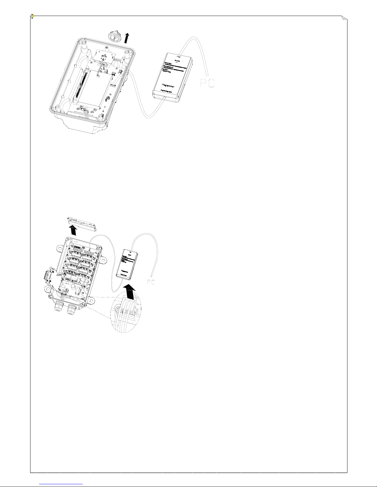
52
(Fig. 20)
(Fig. 21)
2. Install Alpha 6000 software and click open. (Alpha6K.exe for windows XP /Alpha6K_W64.exe for windows 7).
3. Select "Read Memory".
4. After memory data is read successfully, then enter function change setting display.
5. After function setting is completed, change the display to the last page to continue setting. Select “Write-in
Memory (ROM)” to download the setting data to the transmitter.
6. After transmitter setting data is downloaded completely, remove Alpha 6000 programmer USB plug from
encoder board and then plug it into decoder board as shown below. (The system has to be first shutoff.)
7. Click “Write-in Memory (ROM)", then the setting data will be downloaded to receiver and the setting is
completed.
Page 53
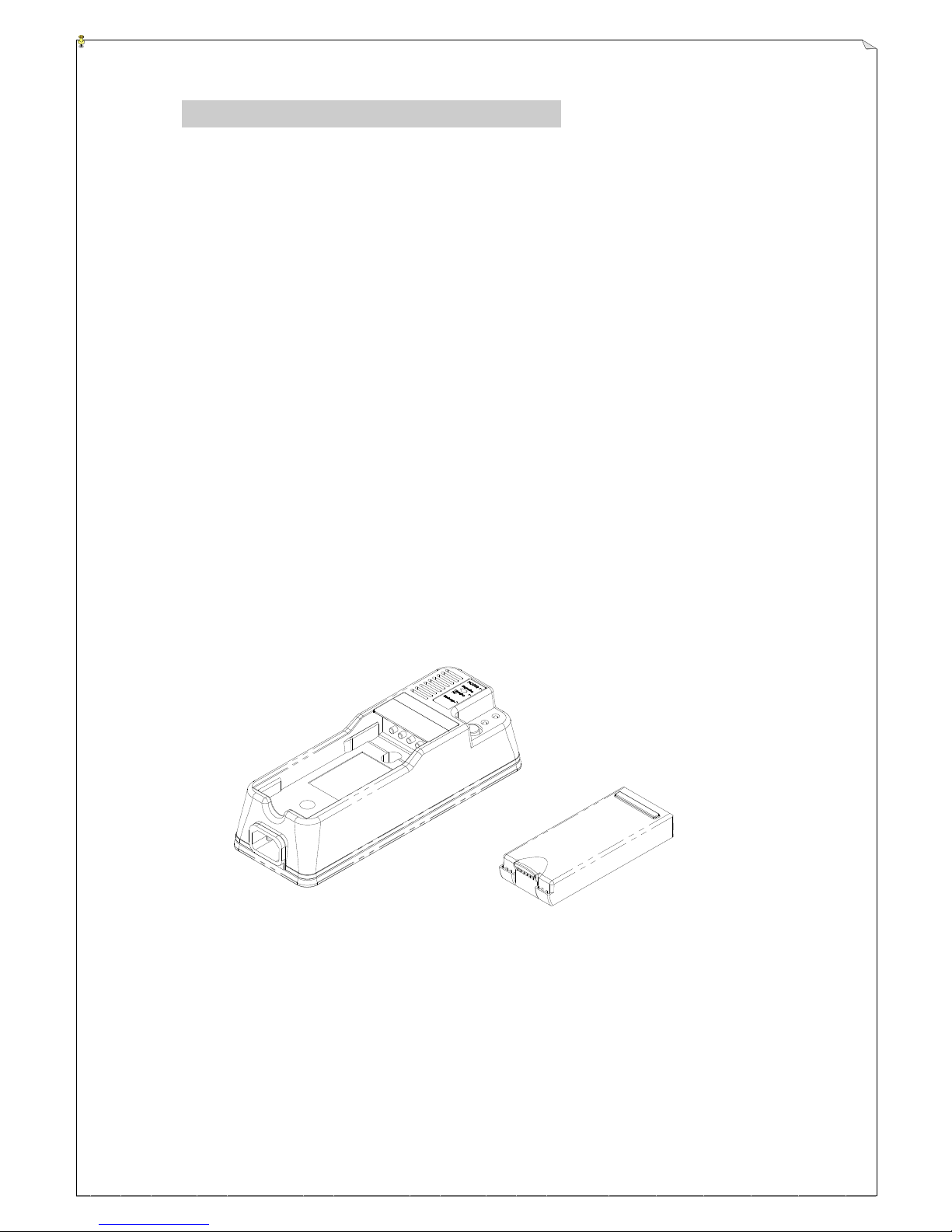
53
8. BATTERY CHARGING
1. Plug in the power cord and the power indicator will light up.
2. When a battery pack is inserted, the green charging light will blink to indicate charging is taking
place at the current moment.
3. If discharging of battery pack is desired, press the “DISCHARGE” button. At discharging mode,
the green blinking light will now turned into a constant red light indicating that the battery pack is
now being discharged. If you want to cancel the discharge, just press “DISCHARGE” button again
4. When discharging is completed, the charger will automatically switch to the charging mode where the
green blinking light will reappear again
5. The charging time is approximately 3 ~ 6 hours.
6. When charging is completed, a constant green light will appear to indicate that the battery pack is
fully charged.
7. When the battery pack is at 90% charged state, trickle charging will take over to ensure the longevity
of the battery pack and as well as to ensure the battery pack is 100% charged
8. When the battery pack’s temperature exceeds 50℃, the charger will go into protective mode and
charging will be discontinued
9. To prolong the life of the battery pack, it is recommended that the battery pack be fully discharged
prior to every re-charging.
Page 54
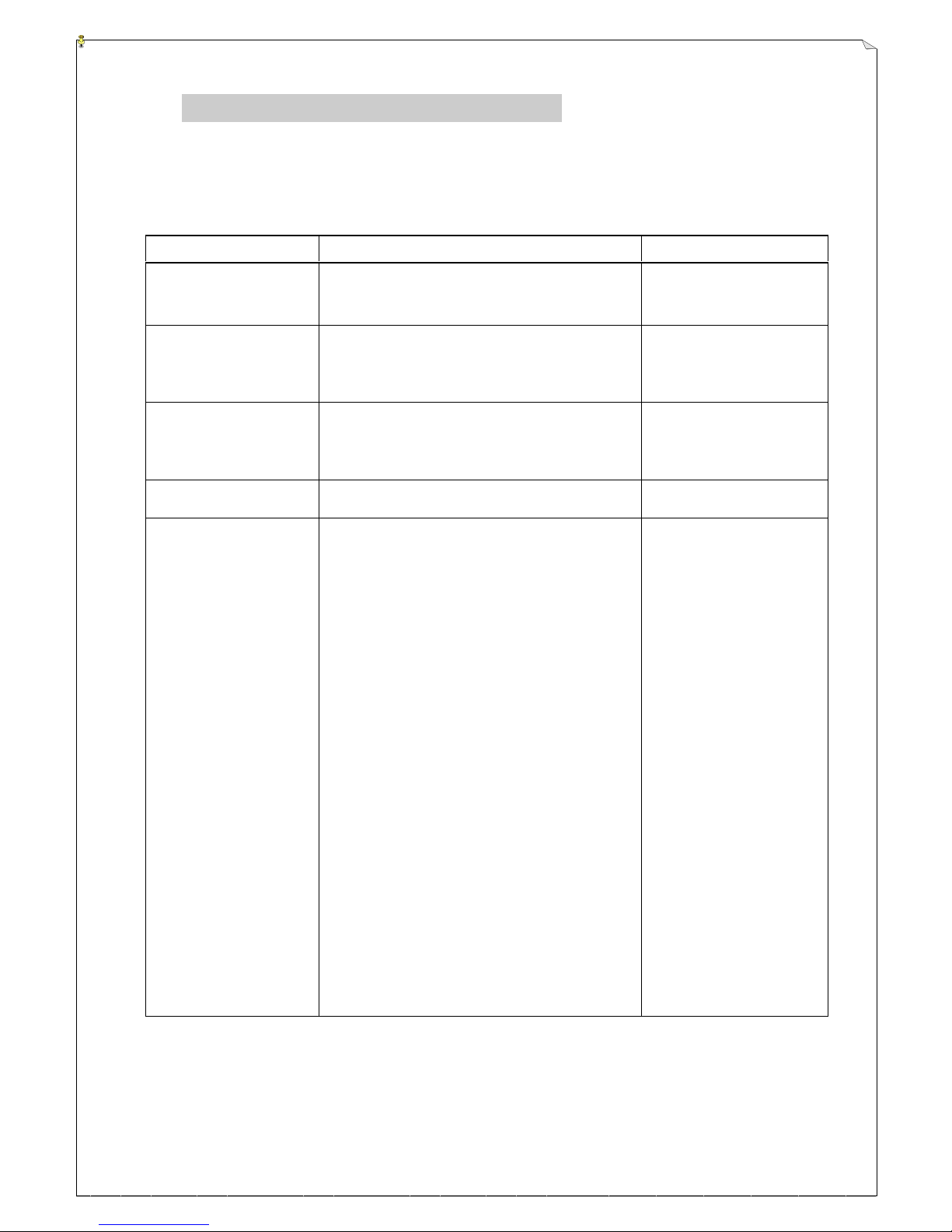
54
9. TROUBLE SHOOTING
Should the operator find the equipment not operating normally, please check the chart below for
simple trouble shooting tips.
POSSIBLE REASON
PROBLEM JUDGEMENT
SOLUTION
Crane malfunctioned
Try to operate the crane by a pendent. If it is
working, then the problem is on the crane
itself.
Repair the crane
1. Transmitter power
is not on.
2. Transmitter battery
voltage is low.
1. Both battery and status LED not lit.
2. Turn “on” the transmitter with EMS elevated.
Battery status LED red light constantly on.
1. Turn on the power
2. Replace the recharg
e-able battery.
No power to the
receiver (AC power
indicator on the
receiver unit not lit).
Check if the power indicator (AC) is
lighted
Ensure power input to
the receiver unit is
correct.
Blown fuse
Check if the fuse has blown
Replace the
Fuse.
Transmitter startup,
pushbutton/joystick
jammed
Under pushbutton jammed condition: First
check which pushbutton/joystick is jammed.
[Status LED]
Red fast blinks: Without jammed
Red blinks twice: Jammed
Description:
Under pushbutton jammed condition: [Status
LED] two red blinks. After all pushbuttons
and joysticks are released, move joystick 1.
If [Status LED] red blinks quickly, it means
joystick 1 is not jammed. If red LED
blinks twice, it means joystick 1 is jammed.
Please check all joysticks by following above
descriptions.
* Enable pushbutton [power startup without
checking pushbutton jammed] checking
bypass.
* [Standard selector switch] [Mixed mode
selector switch][Speed limit switch]
[EID/LID switch] checking bypass.
Replace/repair,
pushbutton/joystick
Page 55

55
10. SYSTEM SPECIFICATION
Transmitter Unit
Frequency Range : PLL 433 ~ 434 MHz / 447 ~ 448 MHz
Transmitting Range: : over 100 Meters
Continuous Operating Time : 28+ Hours (2000mAh)
Operating Current : approx. 70mA
Sleep Mode Current : approx. 10mA
Charging Current : approx. 400mA
Security ID Code : 1,048,576 sets (20 bit)
Shortest Pushbutton Recognizing Time : 5mS
Channel Spacing : 25KHz / 12.5KHz
Frequency Control : VTCXO + Synthesizer (PLL)
Frequency Drift : < 3ppm @ -10℃ ~ 70℃
Frequency Deviation : < 1ppm @ 25℃
Spurious Emission : > 60dBc
Transmitting Power : 1.0mW
Emission : F1D
Antenna Impedance : 50 ohms
Encoding Reference : 2FSK
Encoding Depth : +-2.5KHZ
Enclosure Rating : IP-65
Source Voltage : 7.2 V (2000mAH NiMH battery pack)
Operating Temperature : -10℃ ~ +50℃
Shock Resistant : 50G
Dimension : 268mm X 162mm X 178.5mm
Weight : 1,600g (with 2000mAh battery pack)
Page 56

56
Receiver Unit
Frequency Range : PLL 433 ~ 434 MHz / 447 ~ 448 MHz
Channel Spacing : 25KHz / 12.5KHz
Hamming Distance : ≧ 6
Frequency Control : VTCXO + Synthesizer (PLL)
Frequency Drift : < 3ppm @ -10℃ ~ 70℃
Frequency Deviation : < 1ppm @ 25℃
Sensitivity : ≤ -120dBm
Decoding Reference : 2FSK
Intermediate Frequency
:
21.4MHZ and 455MHZ
Antenna Impedance : 50 ohms
Data Decoder Reference : Quartz Crystals
Radiation Leakage : < -75dBm
Proportional Voltage Output Impedance : ≥ 1kΩ
Proportional Current Output Impedance : ≥ 250Ω
Responding Time : 45mS ~ 150mS
(pushbutton / EMS / joystick)
MAIN off Time after RF Signal Interruption : Approx. 1 second
Enclosure Rating : IP-65
Source Voltage : 100-240VAC @ 50/60 Hz.
Power Consumption : 32W
Operating Temperature : -10℃ ~ +60℃
Shock Resistant : 40G
Output Contact Rating : 250V @ 6A
Dimension : 300mm X 171mm X 115mm
Weight : 4,500g (include the cable gland)
Note: Other types of source voltages are available upon request.
Page 57

57
11. PARTS LIST
1. TX module TX6000
2. RX module card RX6000
3. Proportional output module POM6000
4. Wiring loom WL6000
5. Encoder board EN6000
6. Decoder card DE6000
Decoder card (infrared) DEIR6000
7. LCD display card LCD6000
8. Relay card (8R) RL6008
9. A/G sensor board AG6000
10. Power supply module (100 ~ 240VAC) PS6000
Power supply module (380~460VAC) PS6001
Power supply module (12 ~ 24VDC) PS6002
11. Small single axis joystick unit (complete)
proportional JOY-600
1/2 speeds / steps (digital) JOY-602
3 speeds / steps (digital) JOY-603
4 speeds / steps (digital) JOY-604
5 speeds / steps (digital/proportional) JOY-605
12. Single axis joystick unit (complete)
proportional JOY-610
1/2 speeds / steps (digital) JOY-612
3 speeds / steps (digital) JOY-613
4 speeds / steps (digital) JOY-614
5 speeds / steps (digital/proportional) JOY-615
13. Double axis joystick unit (complete)
proportional JOY-620
1/2 speeds / steps (digital) JOY-622
3 speeds / steps (digital) JOY-623
4 speeds / steps (digital) JOY-624
5 speeds / steps (digital/proportional) JOY-625
14. Joystick rubber boot JOYRB5000
15. Joystick head JOYH5000
16. 1-step pushbutton (side panel) PB-1S
17. 1-step pushbutton (top panel) PB-1T
18. 2-stage selector switch SW-2T
19. 3-stage selector switch SW-3T
20. 2-stage toggle switch TW-2T
21. 3-stage toggle switch TW-3T
22. Emergency stop button EM5000
Page 58

58
23. Transmitter casing (complete) TC6000
24. Transmitter protective guardrail + hardware PG5000
25. Transmitter power key PW5000
26. 2000mAh NiMH battery pack BAT2000
27. Receiver antenna (419/433/447 MHz) ANT433
28. Receiver upper enclosure RCU6000
Receiver bottom enclosure RCB6000
Receiver enclosure (complete) RC6000
29. Regular relay 12VDC RR6000_12VDC
30. Safety relay 12VDC SR6000_12VDC
31. Receiver shock absorber (4pcs/set) SA4000
32. Intelligent charger (please specify voltage) CH5000
33. Waist belt WB5000
34. Shoulder strap SS5000
35. Cable gland CG4000
36. Labels for top pushbuttons TPBL5000
37. Labels for side pushbuttons SPBL5000
38. Joystick gates GA5000
 Loading...