

Fomotech Alpha 500, Alpha 520, Alpha 540, Alpha 560, Alpha 580 User Manual

1
TTAABBLLEE OOFF CCOONNTTEENNTTSS
Page
1. INTRODUCTION ....................................................................................................... 2
2. SAFETY INSTRUCTION ............................................................................................. 3
3. PUSHBUTTON CONFIGURATION
3.1 Alpha 500 & 520 Models ..................................................................................... 4
3.2 Alpha 540 & 560 Models ..................................................................................... 5
3.3 Alpha 580 Models ............................................................................................... 6
4. TRANSMITTER OUTLINE
4.1 Alpha 500 & 520 Models ..................................................................................... 7
4.2 Alpha 540 & 560 Models ..................................................................................... 8
4.3 Alpha 580 Models ............................................................................................... 9
5. RECEIVER OUTLINE
5.1 Alpha 500 ~ 560 Models External Assembly ....................................................... 10
5.2 Alpha 500 & 520 Models Internal Assembly ....................................................... 11
5.3 Alpha 540 & 560 Models Internal Assembly ....................................................... 12
5.4 Alpha 580 Models External Assembly ................................................................. 13
5.5 Alpha 580 Models Internal Assembly ................................................................. 14
6. OUTPUT CONTACT DIAGRAMS
6.1 Alpha 500 & 520 Models ..................................................................................... 15
6.2 Alpha 540 Models ................................................................................................. 16
6.3 Alpha 560 Models ................................................................................................. 17
6.4 Alpha 580 Models ................................................................................................. 18~20
7. SYSTEM CONFIGURATIONS
7.1 How to Set Jumper Functions ............................................................................. 21~22
7.2 How to Set ID Codes ............................................................................................. 22
7.3 Receiver RF Channel Setting ............................................................................. 23
7.4 How to Remove the Transmitter RF Board ......................................................... 23
7.5 Alpha 580 Pushbutton Function Settings ............................................................. 24~25
7.6 Frequency (RF) Channel Table ............................................................................. 26
8. RECEIVER INSTALLATION
8.1 Preparation For Installation ................................................................................... 27
8.2 Step-By-Step Installation ....................................................................................... 27
8.3 System Testing ....................................................................................................... 28
9. TRANSMITTER OPERATION ................................................................................... 29~31
10. TROUBLE SHOOTING ............................................................................................... 32
11. SYSTEM SPECIFICATION ......................................................................................... 33
12. PARTS LIST ................................................................................................................. 34~35

2
11.. IINNTTRROODDUUCCTTIIOONN
The Alpha 500 series are highly durable, reliable and safe industrial radio remote control systems. The
versatile features of the Alpha 500 series permit their use in many different remote control applications.
The systems can be used to control factory cranes, monorail systems, multiple hoists, trolleys, mining
equipment, building construction equipment, automatic control systems, and many others.
The system incorporates numerous redundant safety circuits that guaranty maximum security and
ensure the system is resistant to outside interference. The major features of the Alpha 500 series are as
follow:
* The system uses advanced microprocessors with highly evolved software that has redundant
error checking and correcting capabilities to ensure 100% error-free transmission, decoding, and
control of all output relays. This highly evolved software includes CRC (Cyclical Redundancy
Check Code) and Hamming Codes (Error Recovery) programming.
* To insure maximum operating safety, the Alpha 500 series incorporates numerous important
safety features. Some of these built in safety features include transmitter pushbutton
self-diagnosing during initial startup, transmitter low-voltage detection and visual warning with
additional output for external warning light connection (LV relay), receiver self-diagnosing,
MAIN deactivation during transmitter low-voltage, when system is in sleep mode, when system
encountering strong RF interference, and when the transmitter is out of the receiving range.
* The transmitter encoder and receiver decoder both utilize advanced microprocessor control. The
availability of 32,768 sets of unique ID codes + 30 distinct RF channels will ensure that only
commands from the matching control transmitter can be carried out without any interference
from other radio systems.
* For added safety, the system also incorporates special type of safety MAIN contact relay or relays.
If the safety MAIN relay becomes defective (fails to open or close during operation or not
responding to a “stop” command), it will signal the system to shut down immediately to avoid the
possibility of any accidents occurring.
* 30 sets of user-adjustable receiving RF channels plus special designed removable transmitting
RF board for easy channel replacement and service maintenance.
* Waterproofed transmitter and receiver enclosures, including the battery compartment.
The Alpha 500 series radio remote control systems consist of water-resistant IP-66 transmitters and
IP-65 / IP-66 receivers. All receiver s are equipped with a 2-meter pre-wired output cable (Alpha 500
~ 560 models). The transmitter casings are molded using industrial strength composite materials
which are impervious to dust, water, oil, acids, alkaline, heat and sunlight as well as being resistant to
deformation due to long term use in harsh environments. The pushbuttons are also constructed from
industrial strength composite materials with minimum of up to one million press cycles. For battery
power savings, the transmitter is designed and manufactured with a special ultra-efficiency
power-saving circuit that requires only two “AA” size alkaline batteries for more than 150 hours of
continuous operation.

3
22.. SSAAFFEETTYY IINNSSTTRRUUCCTTIIOONN
The Alpha 500 series are relatively simple to use, however, it is very important to observe the proper
safety procedures before, during, and after operation. When used properly, the Alpha 500 series will
enhance safety, productivity and efficiency in the workplace.
The following procedures should be strictly followed:
1. Check the transmitter casing and pushbuttons daily. Should any damage that could inhibit the
proper operation of the transmitter be found the unit should be immediately removed from
service.
2. The transmitter voltage should be checked on a daily basis. If the voltage is low (red status light
blinking or completely off), the two “AA” alkaline batteries should be replaced.
3. The red emergency stop button (EMS) should be checked at the beginning of each shift to ensure
it is in proper working order and the “Stop” command is being received by the receiver.
4. In the event of an emergency press down the EMS button will immediately deactivates the
receiver MAIN relay and the transmitter power. Then turned the power “off” from the main
power source to the crane or equipment.
5. The transmitter power switch should be turned off after each use and should never be left in the
“power on” state when the unit is unattended.
6. Do not use the same RF channel and ID code as any other system in use at the same facility or
within 300-meter distance.
7. Ensure the wrist strap (Alpha 500 ~ 560 models) or the waist belt (Alpha 580 models) is worn at
all time during operation to avoid accidental damage to the transmitter.
8. Never operate a crane or equipment with two transmitters at the same time with the same RF
channel and ID code, as it will cause radio interference.
Caution!
Improper Storage of your Spare Transmitter is a Safety Hazard! During the initial installation
of your remote control system the spare (second) transmitter should be tested to confirm that it
is functioning properly and then the batteries must be removed and the transmitter stored in a
secured place. Failure to follow this safety procedure can result in the inadvertent operation of
your crane or hoist by unauthorized personnel resulting in serious injury or death!
15.21 ¡§Changes or modifications are not expressly approved by the manufacturer could void
the user's authority to operate the equipment.¡¨
"Operation is subject to the following two conditions: (1) this device may not cause interference,
and (2) this device must accept any interference, including interference that may cause undesired
4
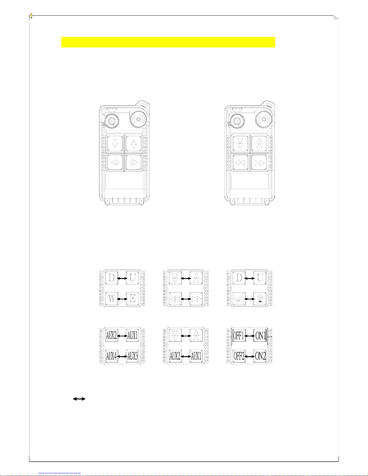
33.. PPUUSSHHBBUUTTTTOONN CCOONNFFIIGGUURRAATTIIOONN
33..11 AAllpphhaa 550000 && 552200 MMooddeellss
1. Alpha 500 : (4) one-speed pushbuttons.
2. Alpha 520 : (4) two-speed pushbuttons.
(Alpha 500) (Alpha 520)
Below are some of many types of pushbutton configurations that are also available, please
contact your dealer for more details.
Interlocked (Can also be set to non-interlocked via an external programmer unit).
ON OFF
STOP
STOP
ON OFF

5
33..22 AAllpphhaa 554400 && 556600 MMooddeellss
1. Alpha 540S : (6) one-speed pushbuttons.
2. Alpha 540A : (6) one-speed pushbuttons + (1) AUX micro-button.
3. Alpha 560S : (6) two-speed pushbuttons.
4. Alpha 560A : (6) two-speed pushbuttons + (1) AUX micro-button.
(Alpha 540S) (Alpha 540A)
(Alpha 560S) (Alpha 560A)
6
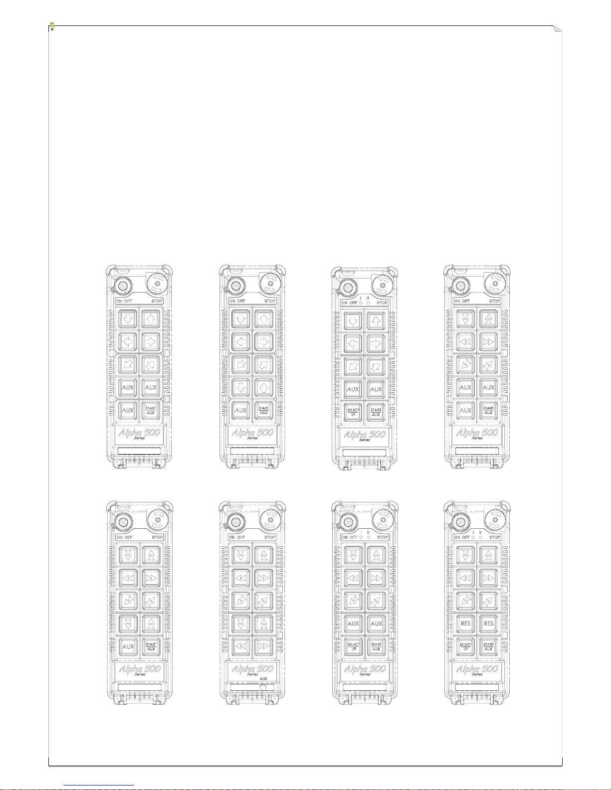
33..33 AAllpphhaa 558800 MMooddeellss
1. Alpha 580A-1 : (10) one-speed pushbuttons (labeled as 3 motions).
2. Alpha 580A-2 : (10) one-speed pushbuttons (labeled as 4 motions).
3. Alpha 580B : (9) one-speed pushbuttons + (1) SELECT I/II pushbutton.*
4. Alpha 580C-1 : (6) two-speed + (4) one-speed pushbuttons.
5. Alpha 580C-2 : (8) two-speed + (2) one-speed pushbuttons.
6. Alpha 580D : (10) two-speed pushbuttons + (1) AUX micro-button.
7. Alpha 580E : (6) two-speed + (3) one-speed pushbuttons + (1) SELECT I/II pushbutton.*
8. Alpha 580F : (8) two-speed + (1) one-speed pushbutton + (1) SELECT I/II pushbutton.*
* For cranes with auxiliary hoist and trolley (changeover function).
(Alpha 580A-1) (Alpha 580A-2) (Alpha 580B) (Alpha 580C-1)
(Alpha 580C-2) (Alpha 580D) (Alpha 580E) (Alpha 580F)

7
14
15
16
O
n
1
2
3
4
7
5
6
8
17
44.. TTRRAANNSSMMIITTTTEERR OOUUTTLLIINNEE
44..11 AAllpphhaa 550000 && 552200 MMooddeellss
(Fig. 1) Front View (Fig. 2) Back View
(Fig. 3) Front View (Fig. 4) Back View
1) Transmitter enclosure 8) Pushbutton # 3 (→ / East) 15) Programming port
2) Power switch (ON/OFF) 9) System information 16) ID code dip-switch
3) Pushbutton #2 (↓ / Down ) 10) Battery cover 17) Transmitting RF Board
4) Pushbutton #4 (← / West) 11) Battery cover screws
5) Wrist strap attachment 12) Internal antenna
6) Emergency stop (EMS) 13) Status LED display
7) Pushbutton #1 (↑ / Up) 14) Battery contact
1
2
3
4
5
6
7
8
9
10
11
ON OFF
STOP

8
O
n
1
2
3
4
7
5
6
8
44..22 AAllpphhaa 554400 && 556600 MMooddeellss
(Fig. 5) Front View (Fig. 6) Back View
(Fig.7) Front View (Fig. 8) Back View
1) Transmitter enclosure 8) Pushbutton #1 (↑ / Up) 15) Status LED display
2) Power switch (ON/OFF) 9) Pushbutton #3 (→ / East) 16) Battery contact
3) Pushbutton #2 (↓ / Down) 10) Pushbutton #5 (↗ / North) 17) AUX micro-button connector*
4) Pushbutton #4 (← / West) 11) System information 18) Programming port
5) Pushbutton #6 (↙ / South) 12) Battery cover screws 19) ID code dip-switch
6) Wrist strap attachment 13) Battery cover 20) Transmitting RF board
7) Emergency stop (EMS) 14) Internal antenna
* For Alpha 540A and Alpha 560A models only.

9
1
2
3
4
5
6
7
8
10
17
18
16
9
11
12
13
14
15
20
21
22
23
24
25
19
44..33 AAllpphhaa 558800 MMooddeellss
(Fig. 9) Front View (Fig. 10) Back View
(Fig. 11) Front View (Fig. 12) Back View
1) Transmitter enclosure 9) Waist belt attachment 17) Battery cover screws
2) External antenna port 10) Emergency stop (EMS) 18) Battery cover
3) Power switch (ON/OFF) 11) Pushbutton #1 (↑ / Up) 19) Internal antenna
4) Pushbutton #2 (↓ / Down) 12) Pushbutton #3 (→ / East) 20) Status LED display
5) Pushbutton #4 (← / West) 13) Pushbutton #5 (↗ / North) 21) Battery contact
6) Pushbutton #6 (↙ / South) 14) Pushbutton #7 (A1) 22) AUX micro-button connector*
7) Pushbutton #8 (A2) 15) Pushbutton #9 (A3) 23) Programming port
8) Pushbutton #10 (A4) 16) System information 24) ID code dip-switch
25) Transmitting RF board
* For optional AUX micro-button or buttons.

10
55.. RREECCEEIIVVEERR OOUUTTLLIINNEE
55..11 AAllpphhaa 550000 ~~ 556600 MMooddeellss EExxtteerrnnaall AAsssseemmbbllyy
(Fig. 13) Front View (Fig. 14) Back View
1) Receiver enclosure 5) System frequency 9) Supplied voltage
2) Wiring diagram 6) System serial number 10) Anti-vibration spring
3) Receiver LED displays* 7) System ID code 11) Grounding (GND)
4) Type model 8) System RF channel
* A ~ AUX Relay Contact Indicator (for Alpha 540A/560A models only).
* M ~ MAIN and 2
nd
Speed Relay Contact Indicator.
Green "on" → MAIN activated (All models).
Red "on" → 2
nd
speed activated (for Alpha 560S/A models only).
* SQ ~ RF Signal Indicator (Red).
"on" → RF signal detected and received.
"off" → No RF signal detected or received.
Blinking at transmitter power "off" → Other radio interference.
* AC ~ Power Source Indicator (red) "on" → AC input power supplied.
"off" → No AC input power.
1A
POWER
AC220V 50/60HZ
must be grounded
Anti-vibration spring
5A
N/S
5A
5A
5A
LV,AUX
E/W
MAIN
U/D
5A
AC
SQ
M
A
W
S
N
E
U
D
AC
SQ
M
A
4
5
6
7
9
8
2
3
1
10
11
11
1
2
3
4
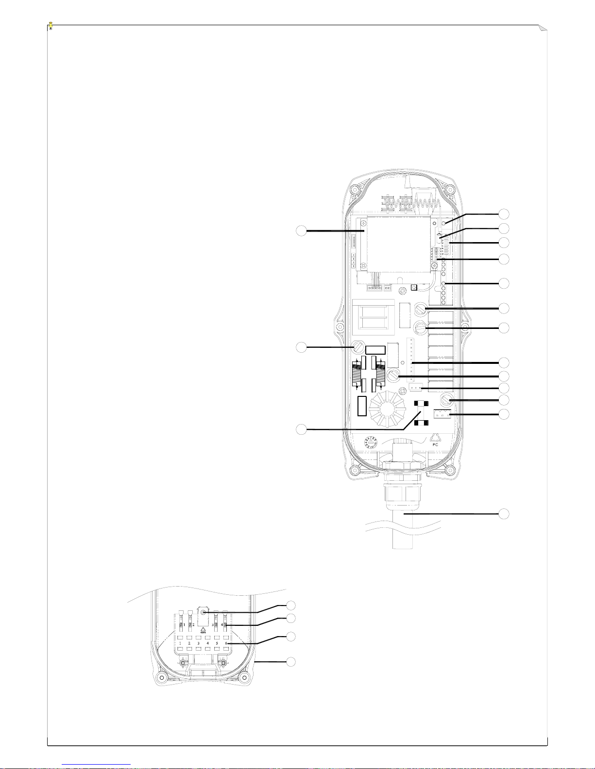
55..22 AAllpphhaa 550000 && 552200 MMooddeellss IInntteerrnnaall AAsssseemmbbllyy
(Fig. 15) Internal Parts Assembly
1) Receiving RF module
2) Secondary power AC fuse (0.50A)
3) Primary power AC fuse (1.0A)
4) System status LED display*
5) External antenna port
6) ID code dip-switch
7) RF channel dip-switch
8) Contact relay LED display
9) Pushbutton #1 and #2 fuse (5.0A)
10) MAIN fuse (5.0A)
11) Contact output seat (CN3)
12) Low-voltage (LV) fuse (5.0A)
13) Contact output seat (CN4)
14) Pushbutton #3 and #4 fuse (5.0A)
15) AC power input seat (CN2)
16) Cable gland & output cable
* Please refer to page 32 for system status
LED display information.
1) Spare fuse & jumper compartment
2) Spare Jumper slots
3) Spare fuse slots
4) Receiver top casing
3
7
6
8
9
10
11
12
14
15
5
13
16
F
U
S
E
F
U
S
E
F
U
S
E
F
U
S
E
F
U
S
E
1
2
4
 Loading...