

Fomotech ALPHA510SERIES Users Manual

TTAABBLLEE O
OFF CC
ONNTTEENNTTSS
O
Page
1

1.
INTRODUCTION
The Alpha 580 is highly reliable industrial remote control system. The versatile features of the
Alpha 580 permit its use in many different remote control applications. The system can be used
to control cranes, hoists, trolleys, mining equipment, building construction equipment,
automatic control systems, and many others.
The Alpha 580 radio control system incorporates numerous redundant safety circuits that
guaranty maximum security and ensure the system is resistant to outside interference. The
major features of the Alpha 580 are as follow:
* The system uses advanced microprocessors which utilizes highly evolved software that
have redundant error checking and correcting capabilities to ensure 100 % error-free
transmission, decoding, and control of the output relays. These highly evolved software
include CRC (Cyclic Redundancy Check codes) and Hamming Codes.
* To insure maximum operating safety, the Alpha 500 series incorporate many safety features.
Some of these safety features include receiver self-diagnosing, transmitter pushbutton
self-diagnosing, transmitter low voltage detection/warning, and transmitter/receiver auto
shutdown after 1 minute of transmitter low voltage warning.
* The encoder/decoder system utilizes advanced microprocessor. The availability of 32,768
sets of unique ID codes will ensure that only commands from the matching control
transmitter can be carried out without any interference from other radio systems. A special
programmable integrated circuit is used to insure the unit can not simultaneously command
conflicting movements.
* Full SMT design for system stability.
The Alpha 580 radio control system consists of a transmitter handheld, and a receiver unit. The
transmitter casing is molded using an industrial strength composite material which is impervious
to dust, water, oil, acids, alkaline, heat, sunlight, and as well as being resistant to deformation
due to long term use in harsh environments. The pushbuttons are also constructed from
industrial strength composite material with a minimum of up to one million cycles. For power
saving, the transmitter unit uses special high efficiency power saving circuits that requires only
two “AA” alkaline batteries (UM-3).

2.
SAFETY INSTRUCTION
The Alpha 580 system is relatively simple to use. However, it is very important to observe the
proper safety procedures during operation. When use properly the Alpha 580 system will
enhance productivity and efficiency in the workplace.
The following instructions should be strictly followed:
1. Make a daily check of the transmitter casing and pushbuttons. Should it appear that
anything could inhibit the proper operation of the transmitter unit, it should be immediately
removed from service.
2. The transmitter voltage should be checked on a daily basis. If the voltage is low, the two
"AA" alkaline batteries should be replaced.
3. The emergency stop pushbutton (EMS) should be checked at the beginning of each shift to
ensure they are in the proper working order.
4. In the event of an emergency, activate the emergency stop pushbutton immediately. Then
turned the power “off” from the main power source of the equipment.
5. The power switch should be turned “off” after use and should never left the power “on”
when the unit is unattended.
6. Do not use the same RF channel and ID code as any other unit in use at the same facility.
7. Ensure the wrist strap is worn at all time during operation to avoid accidental dropping.
8. Never operate a crane or equipment with two (2) transmitter units at the same time with
same RF channel and ID code.
3
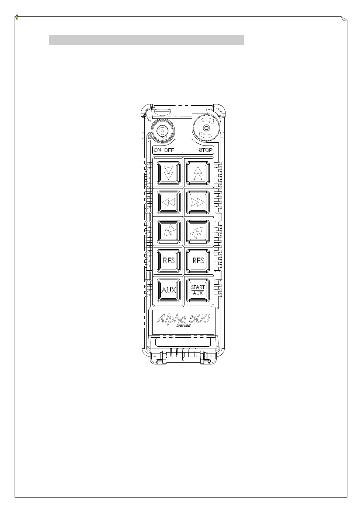
3.
PUSHBUTTON CONFIGURATION
The Alpha 580 model can be configured from 3 to 5 motions with 2-speed pushbuttons and an
emergency stop button (EMS).
(Fig. 1) Pushbutton Placements
RES 2-Speed pushbuttons which can be used for the 4th motion or for any other
functions.
AUX 2-Speed pushbuttons which can be used for the 5th motion or for any other
functions.
4

4.
TRANSMITTER OUTLINE
4.1 External View
(Fig. 2) Front
View
1) Transmitter enclosure 8) Emergency Stop (EMS) 15) Battery Screws
2) Power switch (ON/OFF) 9) Pushbutton #1 16) Batter Cover/FCC ID
3) Pushbutton #2 10) Pushbutton #3
4) Pushbutton #4 11) Pushbuttons #5
5) Pushbutton #6 12) Pushbutton #7 (A1)
6) Pushbutton #8 (A2) 13) Pushbutton #9 (A3)
7) Pushbutton #10 (A4) 14) System Information
5
 Loading...