

Fomotech ALPHA506SERIES, ALPHA504SERIES User Manual

TABLE OF CONTENTS
Page
1. INTRODUCTION ....................................................................................................... 2
2. SAFETY INSTRUCTION ............................................................................................. 3
3. PUSHBUTTON CONFIGURATION
3.1 Alpha 500/520 ....................................................................................................... 4
3.2 Alpha 540/560 ....................................................................................................... 5
3.3 Alpha 540T/560T "Select" Settings ……............................................................. 6
3.4 FCC ID Labels and Numbers ............................................................................... 6
4. TRANSMITTER OUTLINE
4.1 Alpha 500/520 ....................................................................................................... 7
4.2 Alpha 540/560 ....................................................................................................... 8
5. RECEIVER OUTLINE
5.1 Alpha 500/520/540/560 ......................................................................................... 9
5.2 Alpha 500/520 Internal Assembly ......................................................................... 10
5.3 Alpha 540/560 Internal Assembly ......................................................................... 11
6. OUTPUT CONTACT DIAGRAM
6.1 Alpha 500/520 Wiring Diagrams .......................................................................... 12
6.2 Alpha 540 Wiring Diagrams ................................................................................. 13
6.3 Alpha 560 Wiring Diagrams ................................................................................. 14
7. SYSTEM SETTING CONFIGURATION ................................................................... 15~16
8. RECEIVER INSTALLATION
8.1 Preparation For Installation ................................................................................... 17
8.2 Step By Step Installation ....................................................................................... 17
8.3 System Testing ....................................................................................................... 18
9. TRANSMITTER OPERATION ................................................................................... 19 -20
10. TROUBLE SHOOTING ............................................................................................... 21
11. SYSTEM SPECIFICATION ......................................................................................... 22 -23
12. PARTS LIST ................................................................................................................. 24
1

1.
INTRODUCTION
The Alpha 500 series are highly reliable industrial remote control systems. The versatile
features of the Alpha 500 series permit its use in many different remote control applications.
They can be used to control cranes, hoists, trolleys, mining equipment, building construction
equipment, automatic control systems, and many others.
The Alpha 500 series radio control system incorporates numerous redundant safety circuits that
guaranty maximum security and ensure the system is resistant to outside interference. The
major features of the Alpha 500 series are as follow:
* The syste m uses advanced microprocessors which utilizes highly evolved software that
have redundant error checking and correcting capabilities to ensure 100 % error-free
transmission, decoding, and control of the output relays. These highly evolved software
include CRC (Cyclic Redundancy Check codes) and Hamming Codes.
* To insure maximum operating safety, the Alpha 500 series incorporate many safety features.
Some of these safety features include receiver self-diagnosing, transmitter pushbutton
self-diagnosing, transmitter low voltage detection/warning, transmitter/receiver auto
shutdown after 1 minute of transmitter low voltage warning, and receiver MAIN
deactivation during transmitter non-usage (programmable from 0~30 minutes).
* The encoder/decoder system utilizes advanced microprocessor. The availability of 32,768
sets of unique ID codes will ensure that only commands from the matching control
transmitter can be carried out without any interference from other radio systems. A special
programmable inte grated circuit is used to insure the unit can not simultaneously command
conflicting movements.
* Full SMT design for system stability.
The Alpha 500 series radio control system consists of a transmitter handheld, a receiver unit, and
a six -foot (2-meter) output cable. The transmitter casing is molded using an industrial strength
composite material which is impervious to dust, water, oil, acids, alkaline, heat, sunlight, and as
well as being resistant to deformation due to long term use in harsh environments. The
pushbuttons are also constructed from industrial strength composite material with a minimum of
up to one million cycles. For power saving, the transmitter unit uses special high efficiency
power saving circuits that requires only two “AA” alkaline batteries (UM-3).
2

2.
SAFETY INSTRUCTION
The Alpha 500 systems are relatively simple to use. However, it is very important to observe the
proper safety procedures during operation. When use properly the Alpha 500 systems will
enhance productivity and efficiency in the workplace.
The following instructions should be strictly followed:
1. Make a daily check of the transmitter casing and pushbuttons. Should it appear that
anything could inhibit the proper operation of the transmitter unit, it should be immediately
removed from service.
2. The transmitter voltage should be checked on a daily basis. If the voltage is low, the two
"AA" alkaline batteries should be replaced.
3. The emergency stop pushbutton (EMS) should be checked at the beginning of each shift to
ensure they are in the proper working order.
4. In the event of an emergency, activate the emergency stop pushbutton immediately. Then
turned the power “off” from the main power source of the equipment.
5. The power switch should be turned “off” after use and should never left the power “on”
when the unit is unattended.
6. Do not use the same RF channel and ID code as any other unit in use at the same facility.
7. Ensure the wrist strap is worn at all time during operation to avoid accidental dropping.
8. Never operate a crane or equipment with two (2) transmitter units at the same time with
same RF channel and ID code.
3
3.
PUSHBUTTON CONFIGURATION
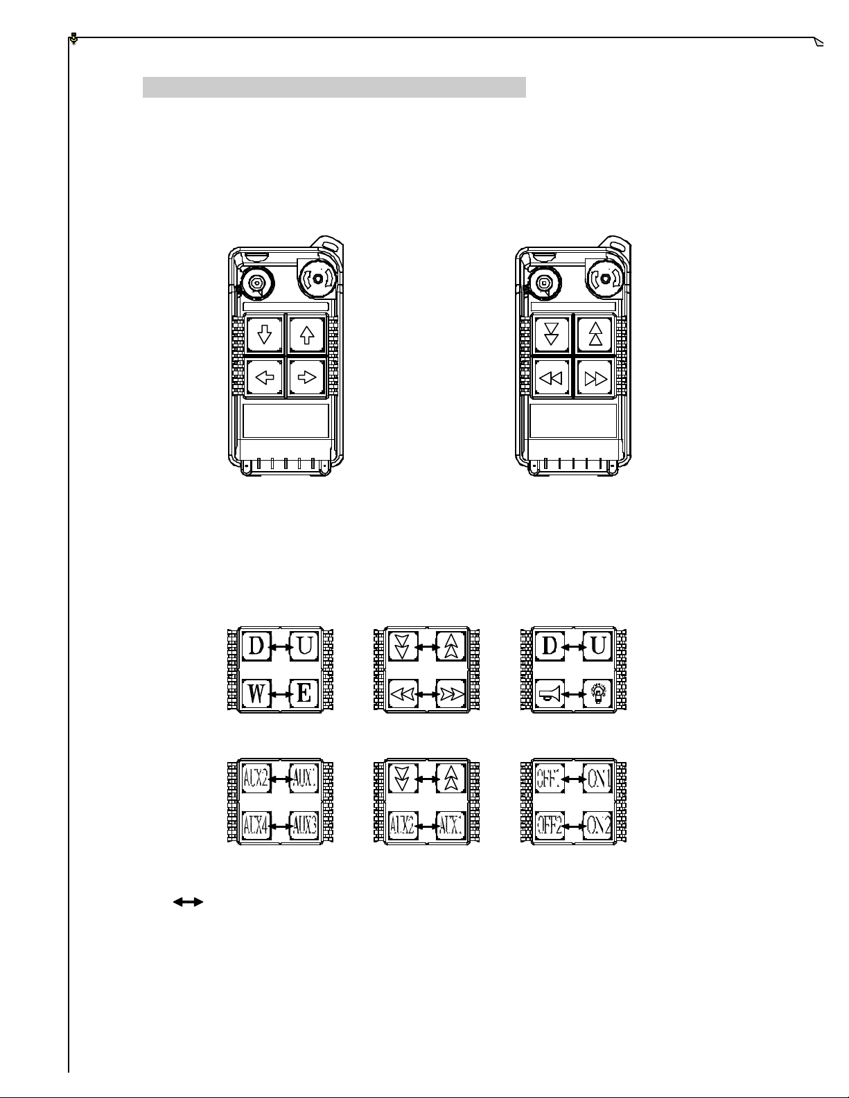
3.1 Alpha 500/520 Models
1. Alpha 500 : Up to 2 motions, single -speed pushbuttons, EMS Stop.
2. Alpha 520 : Up to 2 motions, dual-speed pushbuttons, EMS Stop.
ON OFF STOP STOPON OFF
(Alpha 500) (Alpha 520)
Below are many types of pushbutton configuration that are also available upon request.
Interlocked (can also be set to non-interlocked).
4

3.2 Alpha 540/560 Models
1. Alpha 540S : Up to 3 motions, single -speed pushbuttons, EMS Stop.
2. Alpha 540A : Up to 3 motions, single -speed pushbuttons, AUX, EMS Stop.
3. Alpha 540T : Up to 5 motions, single-speed pushbuttons, “Select” pushbutton for
auxiliary hoist and/or trolley, EMS Stop.
4. Alpha 560S : Up to 3 motions, dual-speed pushbuttons, EMS Stop.
5. Alpha 560A : Up to 3 motions, dual-speed pushbuttons, AUX, EMS Stop.
6. Alpha 560T : Up to 5 motions, dual-speed pushbuttons, “Select” pushbutton for
auxiliary hoist and/or trolley, EMS Stop.
(Alpha 540S) (Alpha 540A) (Alpha 540T)
(Alpha 560S) (Alpha 560A) (Alpha 560T)
5

3.3 Alpha 540T/560T “Select” Pushbutton Function
For Crane system with main and auxiliary hoist, press “Select” pushbutton in
sequence to choose between the two hoists.
1) Power "on" LED-I lit Main hoist active.
2) Press “Select” LED -II lit Auxiliary hoist active.
3) Press “Select” LED-I & LED-II lit Both main and auxiliary hoist active with
duplicate movements.
4) Press “Select” again LED I lit Back to main hoist active.
3.4 FCC ID Labels and Numbers
FCC ID: XXXALPHA504SERIES
FOMOTECH INTERNATIONAL CORP.
This Device complies with Part 15 of the FCC Rules.
Operation is subject to the following two conditions: (1) this
device may not cause harmful interference and (2) this
device must accept any interference received, including
interference that may cause undesired operation.
FCC ID: XXXALPHA506SERIES
FOMOTECH INTERNATIONAL CORP.
This Device complies with Part 15 of the FCC Rules.
Operation is subject to the following two conditions: (1) this
device may not cause harmful interference and (2) this
device must accept any interference received, including
interference that may cause undesired operation.
6

4.
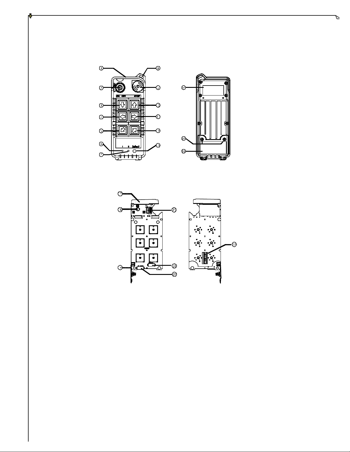
TRANSMITTER OUTLINE
4.1 Alpha 500/520
1
5
2
ON OFF STOP
3
4
6
9
7
8
10
(Fig. 1) Front View (Fig. 2) Back View
12
13
15
11
17
14
16
(Fig. 3) Front View (Fig. 4) Back view
1) Transmitter enclosure 8) Pushbutton # 3 15) TX quartz crystal
2) Power switch (ON/OFF) 9) System information 16) Programming port
3) Pushbutton #2 10) Battery cover/FCC ID 17) ID code dip-switch
4) Pushbutton #4 11) Battery screws
5) Strap ring 12) Antenna
6) Emergency stop (EMS) 13) Status LED display
7) Pushbutton #1 14) Battery contact
7
4.2 Alpha 540/560
(Fig. 5) Front View (Fig. 6) Back View
1
On
2
3
4
5
6
7
8
(Fig. 7) Front View (Fig. 8) Back View
1) Transmitter enclosure 9) Emergency stop (EMS) 17) Antenna
2) Power switch (ON/OFF) 10) Pushbutton #1 18) Status LED display
3) Pushbutton #2 11) Pushbutton #3 19) Battery contact
4) Pushbutton #4 12) Pushbutton #5 20) TX quartz crystals
5) Pushbutton #6 13) Select/AUX pushbutton** 21) Select/AUX
6) Main hoist and/or trolley* 14) System information connector port**
7) Auxiliary hoist and/or trolley* 15) Battery screws 22) Programming port
8) Strap ring 16) Battery cover/FCC ID 23) ID code dip-switch
* For Alpha 540T/560T models only.
** For Alpha 540/560 A and T models only.
8
 Loading...