

Page 1

TABLE OF CONTENTS
Page
1. INTRODUCTION ....................................................................................................... 2
2. SAFETY INSTRUCTION ............................................................................................. 3
3. PUSHBUTTON CONFIGURATION
3.1 Alpha 500/520 ....................................................................................................... 4
3.2 Alpha 540/560 ....................................................................................................... 5
3.3 Alpha 540T/560T "Select" Settings ……............................................................. 6
3.4 FCC ID Labels and Numbers ............................................................................... 6
4. TRANSMITTER OUTLINE
4.1 Alpha 500/520 ....................................................................................................... 7
4.2 Alpha 540/560 ....................................................................................................... 8
5. RECEIVER OUTLINE
5.1 Alpha 500/520/540/560 ......................................................................................... 9
5.2 Alpha 500/520 Internal Assembly ......................................................................... 10
5.3 Alpha 540/560 Internal Assembly ......................................................................... 11
6. OUTPUT CONTACT DIAGRAM
6.1 Alpha 500/520 Wiring Diagrams .......................................................................... 12
6.2 Alpha 540 Wiring Diagrams ................................................................................. 13
6.3 Alpha 560 Wiring Diagrams ................................................................................. 14
7. SYSTEM SETTING CONFIGURATION ................................................................... 15~16
8. RECEIVER INSTALLATION
8.1 Preparation For Installation ................................................................................... 17
8.2 Step By Step Installation ....................................................................................... 17
8.3 System Testing ....................................................................................................... 18
9. TRANSMITTER OPERATION ................................................................................... 19 -20
10. TROUBLE SHOOTING ............................................................................................... 21
11. SYSTEM SPECIFICATION ......................................................................................... 22 -23
12. PARTS LIST ................................................................................................................. 24
1
Page 2

1.
INTRODUCTION
The Alpha 500 series are highly reliable industrial remote control systems. The versatile
features of the Alpha 500 series permit its use in many different remote control applications.
They can be used to control cranes, hoists, trolleys, mining equipment, building construction
equipment, automatic control systems, and many others.
The Alpha 500 series radio control system incorporates numerous redundant safety circuits that
guaranty maximum security and ensure the system is resistant to outside interference. The
major features of the Alpha 500 series are as follow:
* The syste m uses advanced microprocessors which utilizes highly evolved software that
have redundant error checking and correcting capabilities to ensure 100 % error-free
transmission, decoding, and control of the output relays. These highly evolved software
include CRC (Cyclic Redundancy Check codes) and Hamming Codes.
* To insure maximum operating safety, the Alpha 500 series incorporate many safety features.
Some of these safety features include receiver self-diagnosing, transmitter pushbutton
self-diagnosing, transmitter low voltage detection/warning, transmitter/receiver auto
shutdown after 1 minute of transmitter low voltage warning, and receiver MAIN
deactivation during transmitter non-usage (programmable from 0~30 minutes).
* The encoder/decoder system utilizes advanced microprocessor. The availability of 32,768
sets of unique ID codes will ensure that only commands from the matching control
transmitter can be carried out without any interference from other radio systems. A special
programmable inte grated circuit is used to insure the unit can not simultaneously command
conflicting movements.
* Full SMT design for system stability.
The Alpha 500 series radio control system consists of a transmitter handheld, a receiver unit, and
a six -foot (2-meter) output cable. The transmitter casing is molded using an industrial strength
composite material which is impervious to dust, water, oil, acids, alkaline, heat, sunlight, and as
well as being resistant to deformation due to long term use in harsh environments. The
pushbuttons are also constructed from industrial strength composite material with a minimum of
up to one million cycles. For power saving, the transmitter unit uses special high efficiency
power saving circuits that requires only two “AA” alkaline batteries (UM-3).
2
Page 3

2.
SAFETY INSTRUCTION
The Alpha 500 systems are relatively simple to use. However, it is very important to observe the
proper safety procedures during operation. When use properly the Alpha 500 systems will
enhance productivity and efficiency in the workplace.
The following instructions should be strictly followed:
1. Make a daily check of the transmitter casing and pushbuttons. Should it appear that
anything could inhibit the proper operation of the transmitter unit, it should be immediately
removed from service.
2. The transmitter voltage should be checked on a daily basis. If the voltage is low, the two
"AA" alkaline batteries should be replaced.
3. The emergency stop pushbutton (EMS) should be checked at the beginning of each shift to
ensure they are in the proper working order.
4. In the event of an emergency, activate the emergency stop pushbutton immediately. Then
turned the power “off” from the main power source of the equipment.
5. The power switch should be turned “off” after use and should never left the power “on”
when the unit is unattended.
6. Do not use the same RF channel and ID code as any other unit in use at the same facility.
7. Ensure the wrist strap is worn at all time during operation to avoid accidental dropping.
8. Never operate a crane or equipment with two (2) transmitter units at the same time with
same RF channel and ID code.
3
Page 4
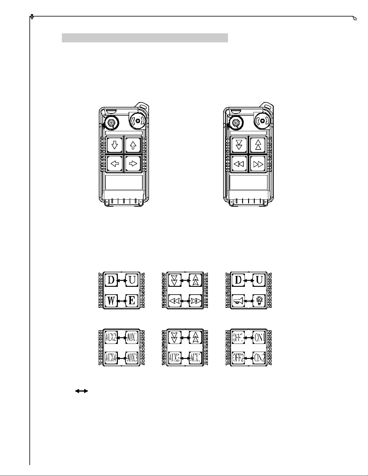
3.
PUSHBUTTON CONFIGURATION
3.1 Alpha 500/520 Models
1. Alpha 500 : Up to 2 motions, single -speed pushbuttons, EMS Stop.
2. Alpha 520 : Up to 2 motions, dual-speed pushbuttons, EMS Stop.
ON OFF STOP STOPON OFF
(Alpha 500) (Alpha 520)
Below are many types of pushbutton configuration that are also available upon request.
Interlocked (can also be set to non-interlocked).
4
Page 5

3.2 Alpha 540/560 Models
1. Alpha 540S : Up to 3 motions, single -speed pushbuttons, EMS Stop.
2. Alpha 540A : Up to 3 motions, single -speed pushbuttons, AUX, EMS Stop.
3. Alpha 540T : Up to 5 motions, single-speed pushbuttons, “Select” pushbutton for
auxiliary hoist and/or trolley, EMS Stop.
4. Alpha 560S : Up to 3 motions, dual-speed pushbuttons, EMS Stop.
5. Alpha 560A : Up to 3 motions, dual-speed pushbuttons, AUX, EMS Stop.
6. Alpha 560T : Up to 5 motions, dual-speed pushbuttons, “Select” pushbutton for
auxiliary hoist and/or trolley, EMS Stop.
(Alpha 540S) (Alpha 540A) (Alpha 540T)
(Alpha 560S) (Alpha 560A) (Alpha 560T)
5
Page 6

3.3 Alpha 540T/560T “Select” Pushbutton Function
For Crane system with main and auxiliary hoist, press “Select” pushbutton in
sequence to choose between the two hoists.
1) Power "on" LED-I lit Main hoist active.
2) Press “Select” LED -II lit Auxiliary hoist active.
3) Press “Select” LED-I & LED-II lit Both main and auxiliary hoist active with
duplicate movements.
4) Press “Select” again LED I lit Back to main hoist active.
3.4 FCC ID Labels and Numbers
FCC ID: XXXALPHA504SERIES
FOMOTECH INTERNATIONAL CORP.
This Device complies with Part 15 of the FCC Rules.
Operation is subject to the following two conditions: (1) this
device may not cause harmful interference and (2) this
device must accept any interference received, including
interference that may cause undesired operation.
FCC ID: XXXALPHA506SERIES
FOMOTECH INTERNATIONAL CORP.
This Device complies with Part 15 of the FCC Rules.
Operation is subject to the following two conditions: (1) this
device may not cause harmful interference and (2) this
device must accept any interference received, including
interference that may cause undesired operation.
6
Page 7

4.
TRANSMITTER OUTLINE
4.1 Alpha 500/520
1
5
2
ON OFF STOP
3
4
6
9
7
8
10
(Fig. 1) Front View (Fig. 2) Back View
12
13
15
11
17
14
16
(Fig. 3) Front View (Fig. 4) Back view
1) Transmitter enclosure 8) Pushbutton # 3 15) TX quartz crystal
2) Power switch (ON/OFF) 9) System information 16) Programming port
3) Pushbutton #2 10) Battery cover/FCC ID 17) ID code dip-switch
4) Pushbutton #4 11) Battery screws
5) Strap ring 12) Antenna
6) Emergency stop (EMS) 13) Status LED display
7) Pushbutton #1 14) Battery contact
7
Page 8
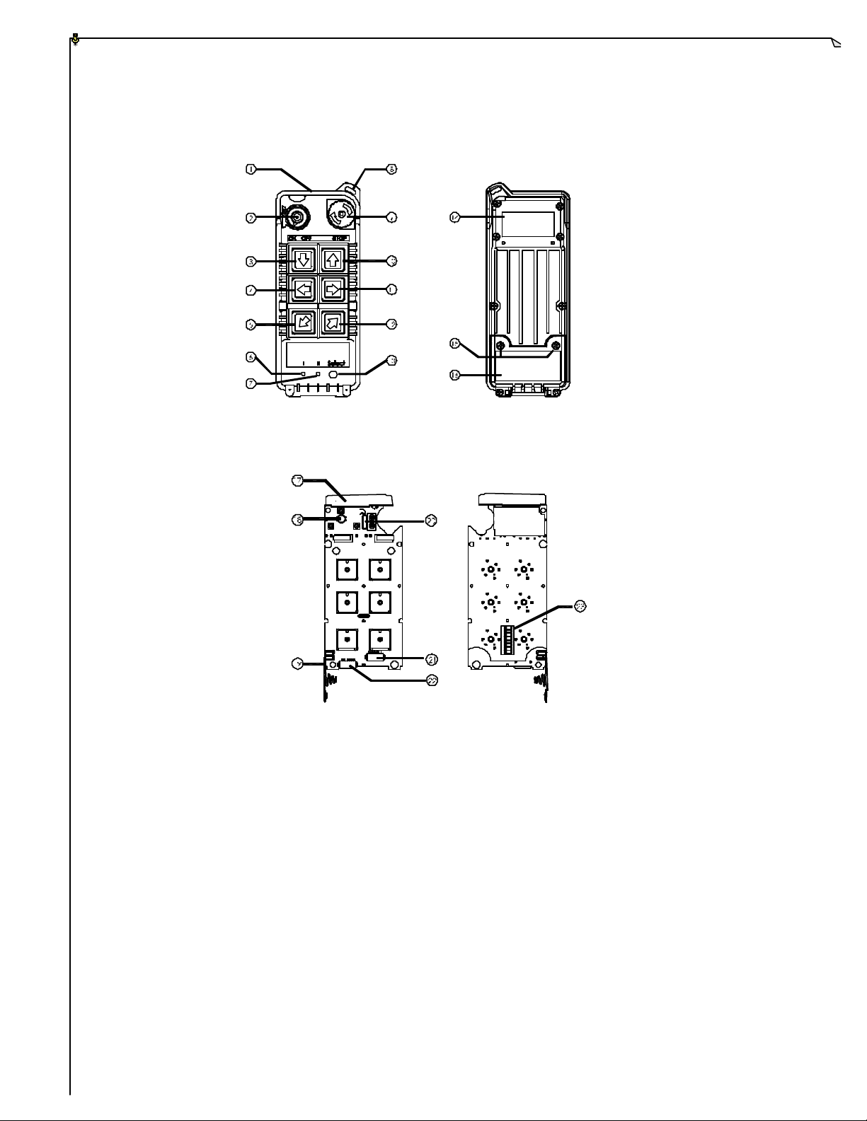
4.2 Alpha 540/560
(Fig. 5) Front View (Fig. 6) Back View
1
On
2
3
4
5
6
7
8
(Fig. 7) Front View (Fig. 8) Back View
1) Transmitter enclosure 9) Emergency stop (EMS) 17) Antenna
2) Power switch (ON/OFF) 10) Pushbutton #1 18) Status LED display
3) Pushbutton #2 11) Pushbutton #3 19) Battery contact
4) Pushbutton #4 12) Pushbutton #5 20) TX quartz crystals
5) Pushbutton #6 13) Select/AUX pushbutton** 21) Select/AUX
6) Main hoist and/or trolley* 14) System information connector port**
7) Auxiliary hoist and/or trolley* 15) Battery screws 22) Programming port
8) Strap ring 16) Battery cover/FCC ID 23) ID code dip-switch
* For Alpha 540T/560T models only.
** For Alpha 540/560 A and T models only.
8
Page 9
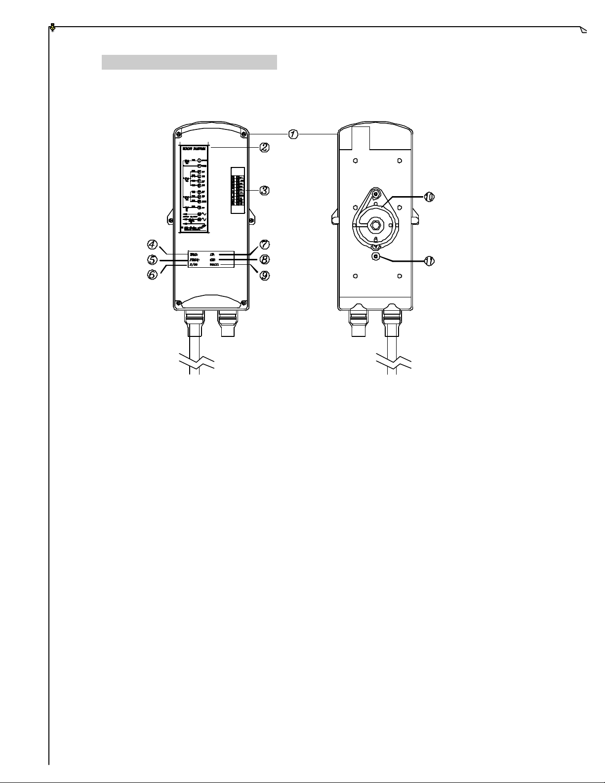
5.
RECEIVER OUTLINE
5.1 All Models
(Fig. 9) Front View (Fig. 10) Back View
1) Receiver enclosure 6) Serial number (S/N)
2) Wiring diagram 7) Security code (ID)
3) Contact relay LED displays* 8) Frequency channel (CH)
4) Model (MOD) 9) Supplied voltage (VOLT)
5) Frequency (FREQ) 10) Anti -vibration spring
11) Grounding (GND)
* A ~ AUX (Alpha 540A/560A ) and “Select” (Alpha 540T/560T) Indicator.
* M ~ MAIN and 2nd Speed Indicator.
Green "ON"
Red "ON" 2nd speed activated (Alpha 560 models only).
* SQ ~ RF Frequency Signal Indicator (Red).
"ON" Signals received (ON 0.1 second and OFF 0.1 second).
"OFF" No frequency signals received.
* AC ~ Power Source Indicator.
MAIN activated.
9
Page 10
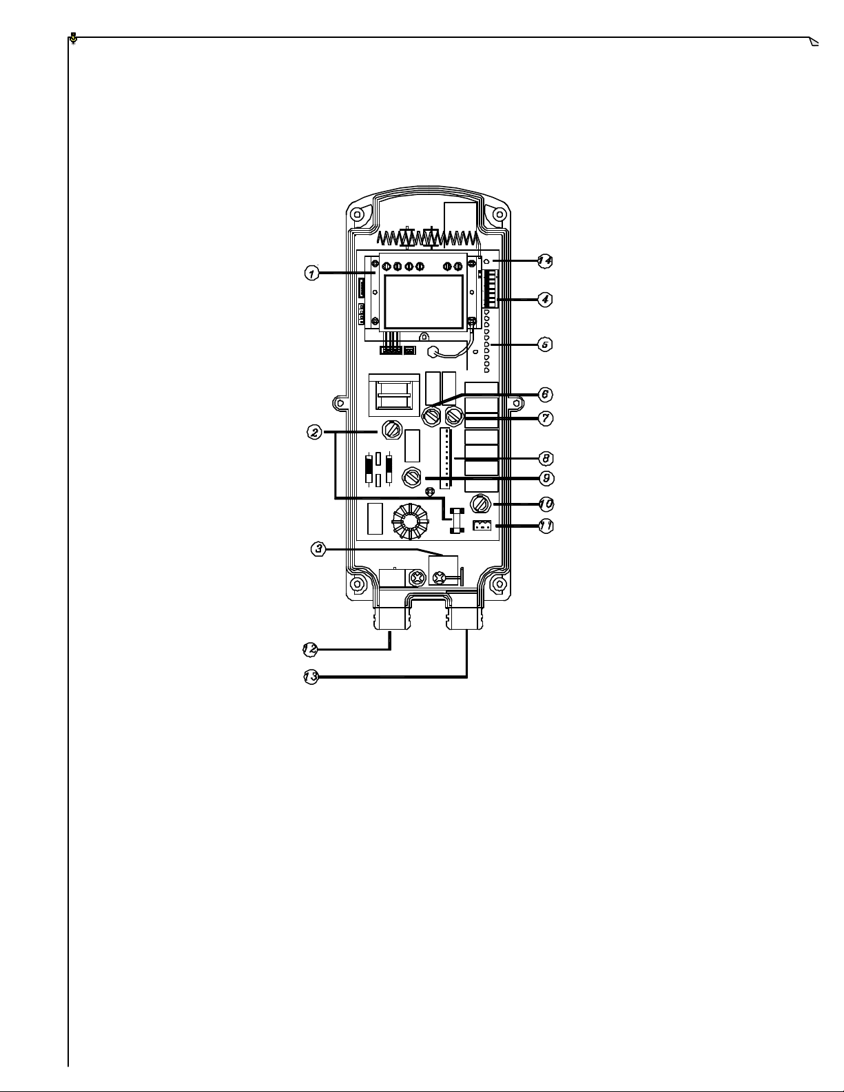
5.2 Alpha 500/520 Internal Assembly
FUSE
FUSE
FUSE
FUSE
FUSE
(Fig. 11) Internal Parts Assembly
1) RX module 8) Contact output seat (CN3)
2) Power fuse (AC) 9) Low voltage warning fuse (LV)
3) Spare fuses & jumpers 10) Pushbutton #3 and #4 fuse
4) ID code dip-switch 11) AC power input seat (CN2)
5) Contact relay LED displays 12) Output cable mouth
6) MAIN fuse 13) Reserved output cable mouth
7) Pushbutton #1 and #2 fuse 14) System status LED display
10
Page 11
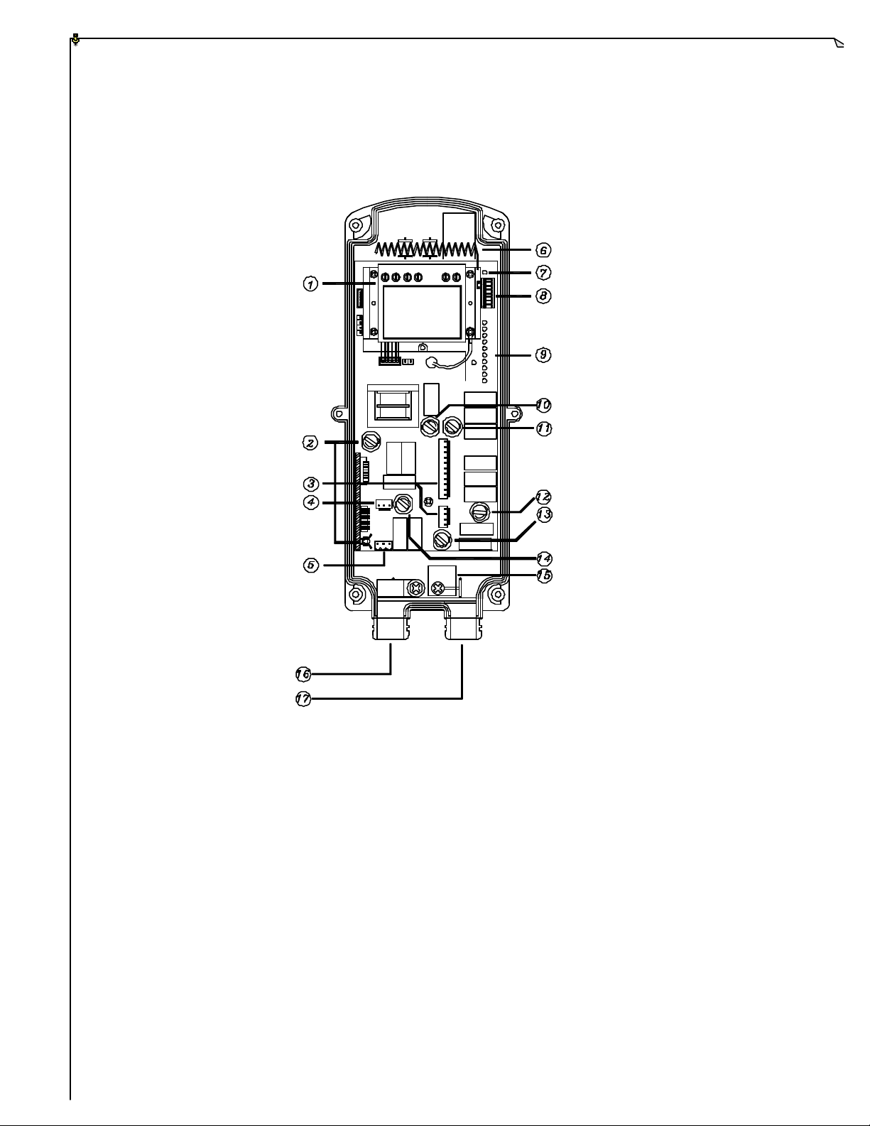
5.3 Alpha 540/560 Internal Assembly
FUSE
FUSE
FUSE
FUSE
FUSE
FUSE
(Fig. 12) Internal Parts Assembly
1) RX module 10) MAIN contact fuse
2) Power fuse (AC) 11) Pushbutton #1 and #2 fuse
3) Contact output (CN3, CN4) 12) Pushbutton #3 and #4 fuse
4) Reserved contact output (CN5) 13) Pushbutton #5 and #6 fuse
5) AC power connector (CN2) 14) Low voltage fuse (Alpha 540S/560S)
6) Antenna LV/AUX fuse (Alpha 540A/560A)
7) System status LED display SELECT fuse (Alpha 540T/560T)
8) ID code dip -switch 15) Spare fuse & jumpers
9) Contact relay LED displays 16) Output cable mouth
17) Reserved output cable mouth
11
Page 12
6.
OUTPUT CONTACT DIAGRAM
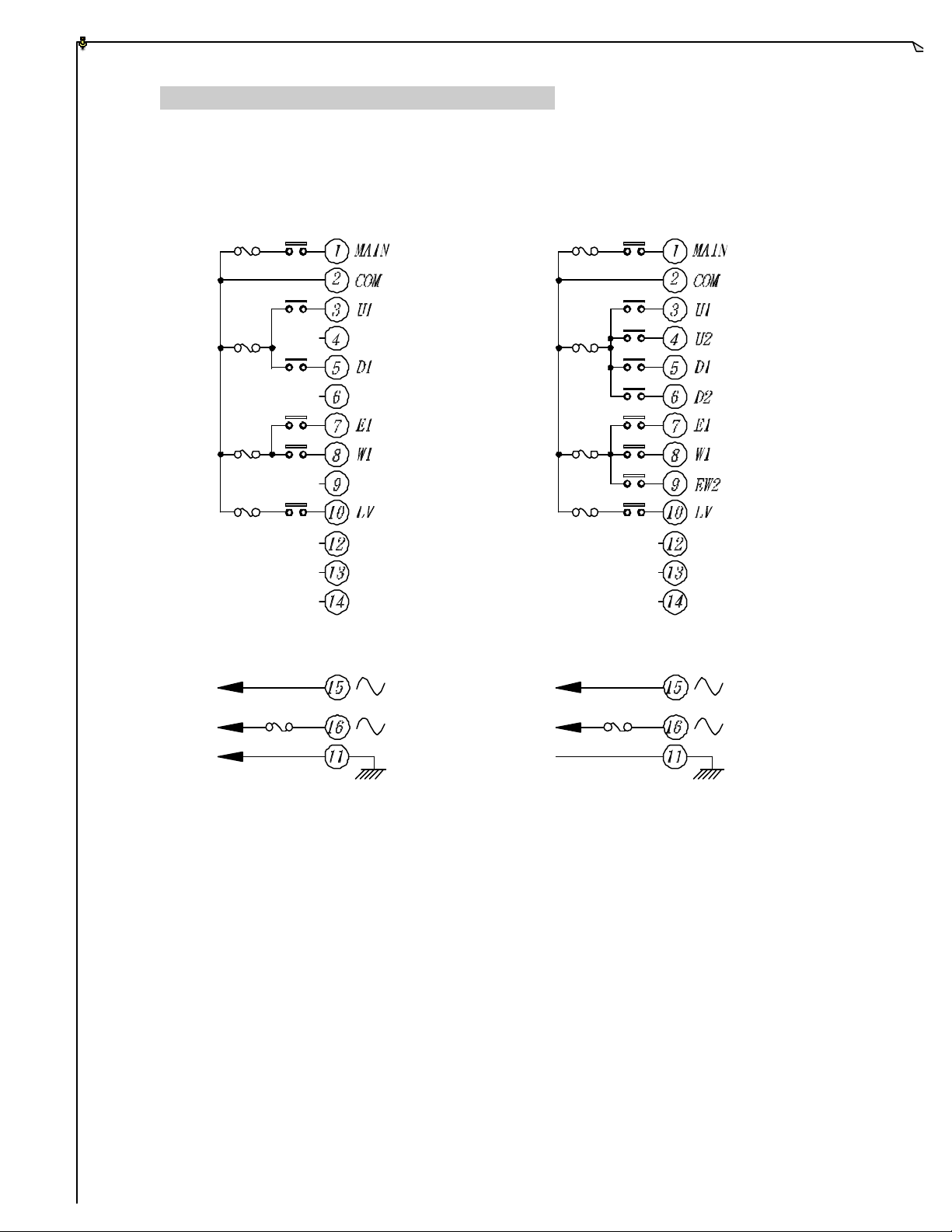
6.1 Alpha 500/520 Wiring Diagram
MAIN
5A
U/D
5A
E/W
5A
LV
5A
NC
NC
NC
NC
NC
NC
MAIN
5A
U/D
5A
E/W
5A
LV
5A
NC
NC
NC
POWER
1A
POWER
1A
(Alpha 500) (Alpha 520)
NC No connection
12
Page 13
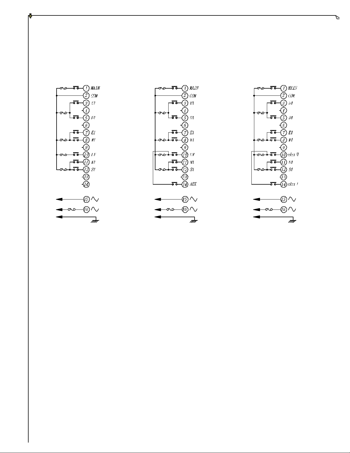
6.2 Alpha 540 Wiring Diagrams
MAIN
5A
U/D
5A
E/W
5A
LV,AUX
5A
N/S
5A
POWER
1A
NC
NC
NC
NC
NC
MAIN
5A
U/D
5A
E/W
5A
LV,AUX
5A
N/S
5A
POWER
1A
MAIN
5A
U/D
5A
E/W
NC
NC
5A
LV,AUX
5A
N/S
5A
POWER
1A
NC
NC
(Alpha 540S) (Alpha 540A) (Alpha 540T)
NC No connection
13
Page 14
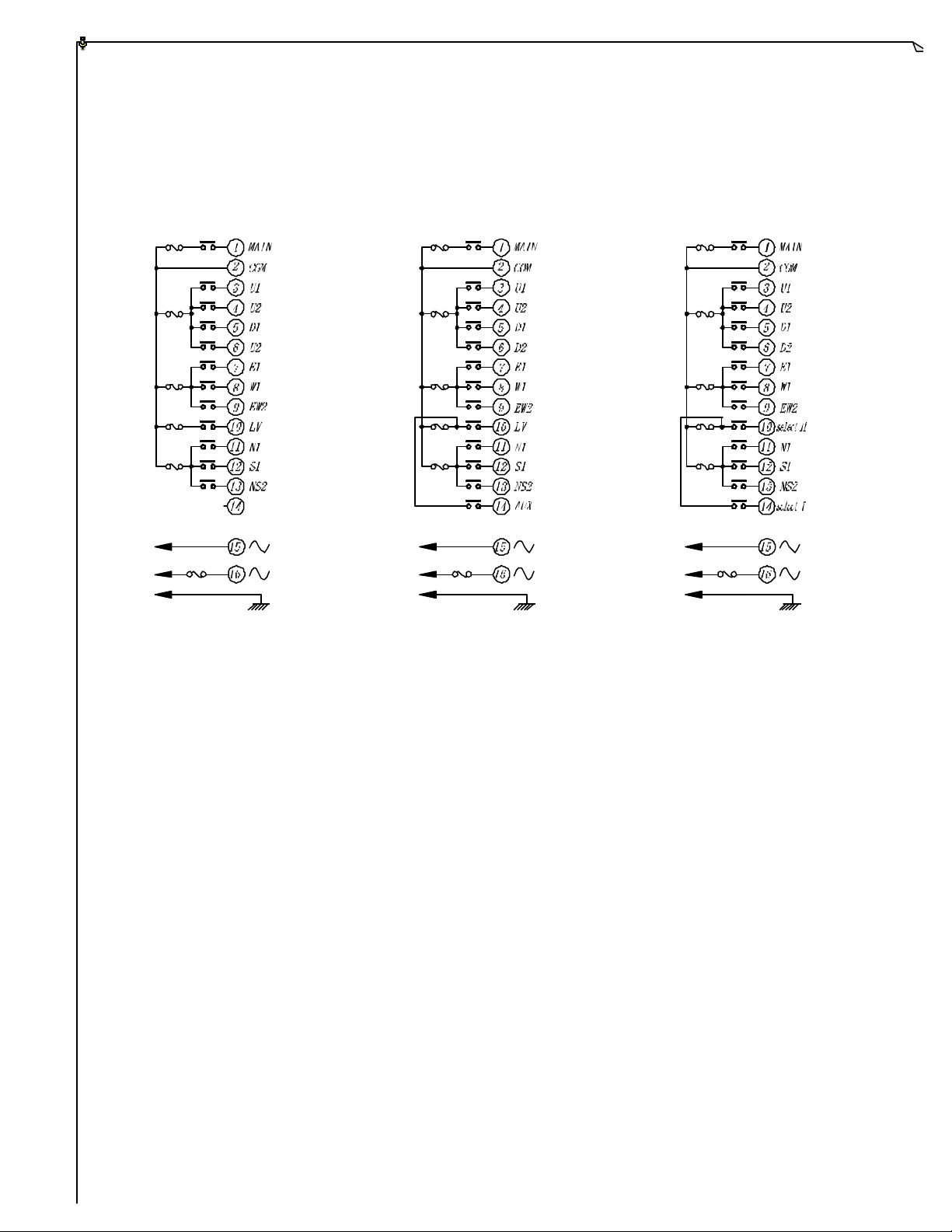
6.3 Alpha 560 Wiring Diagrams
MAIN
5A
U/D
5A
E/W
5A
LV,AUX
5A
N/S
5A
POWER
1A
MAIN
5A
U/D
5A
E/W
5A
LV,AUX
5A
N/S
5A
NC
POWER
1A
MAIN
5A
U/D
5A
E/W
5A
LV,AUX
5A
N/S
5A
POWER
1A
(Alpha 560S) (Alpha 560A) (Alpha 560T)
NC No connection
14
Page 15
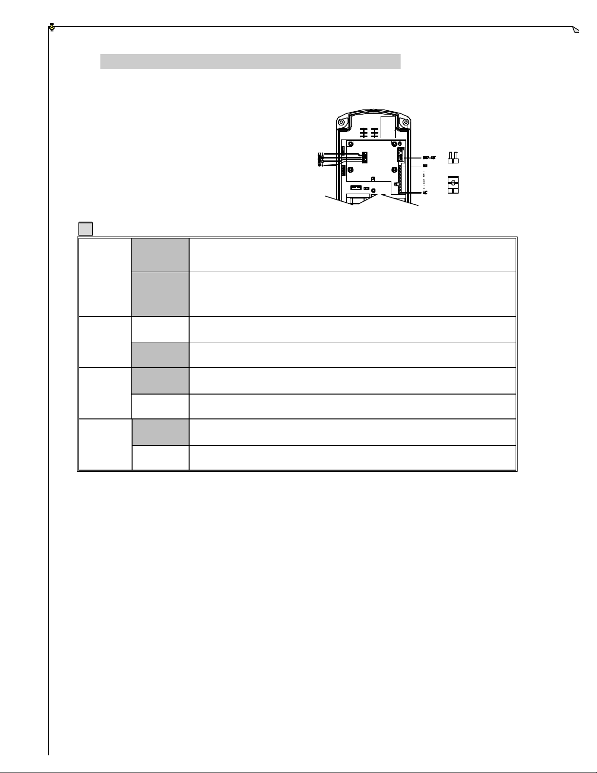
7.
usage (pushbuttons not pressed), receiver MAIN will
ow voltage warning, both the transmitter power and the receiver MAIN
SYSTEM SETTING CONFIGURATION
How To Set Jumper Functions
OPEN¡÷JUMP
SHORT¡÷JUMP
Manufacture settings. * T models do not have LV relay output for external connection.
Manufacture preset for all Alpha 540A/T and 560A/T models
JP1
Open
Short
MAIN. After EMS reset, turn the transmitter power switch “off” and then “on” again to
Press the AUX/SELECT button to activate all transmitter key functions
and the receiver MAIN after transmitter power “on” and After EMS reset
Manufacture preset for all Alpha 500/520/540S/560S models
Turn “on” the power switch to activate all transmitter key functions and the receiver
activate all transmitter key functions and the receiver MAIN.
Open
JP2
Short
Open
JP3
Short
Open
After 5 minutes of transmitter non-
After 1 minute of low voltage warning, only the transmitter power will be
After 1 minute of l
AUX in normal key function (for Alpha 540A/560A only).
Receiver MAIN stays "on” constantly.
be deactivated. (see note A)
deactivated.
will be deactivated. (see note B)
JP4
Short
Note A MAIN shut-off time during system non-operation can be set from 0~30 minutes via external programmer;
manufacture preset at five (5) minutes. To resume operation after five minutes, just press any pushbutton to
reactivate the receiver MAIN.
Note B: If transmitter lo w voltage occurs during operation, other than transmitter itself will display visual warnings, it
will also send out a low voltage signal to the receiver to activate its external low voltage warning device. By
connecting a horn, buzzer, or siren to the LV-relay output will ensure that the operator will clearly notice the
low voltage warning even in hard to see or hear environments. After one minute of low voltage warning, to
insure maximum safety, both the transmitter power and the receiver MAIN will be deactivated.
AUX in toggled key function (for Alpha 540A/560A only).
For proper battery replacement, you must first turn “off” the transmitter power, replace the batteries, and then
turn the power switch back “on” again to reactivate the transmitter and the receiver unit.
15
Page 16
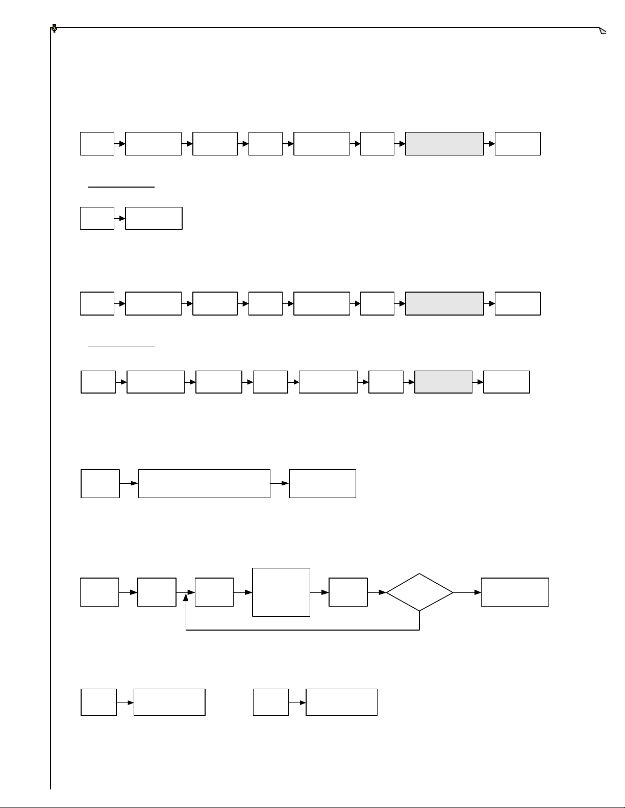
JP1
Transmitter
MAIN
MAIN
Press
MAIN
Reset
Reset
JP1
Transmitter
MAIN
Press
MAIN
Reset
Reset
MAIN
JP1 (Manufacture preset for the Alpha 500/520/540S/540A/560S/560A models)
Short
On
Activated
EMS
Deactivated
EMS
* Reset Power Switch Turn the transmitter power switch “off” and then “on” again.
JP1
Open
Not
Applicable
JP1 (For the Alpha 540T/560T models - Manufacture preset at JP1-Open)
Short
On
Activated
EMS
Deactivated
EMS
* Reset Power Switch Turn the transmitter power switch “off” and then “on” again.
JP1
Open
Transmitter
On
MAIN
Activated
Press
EMS
MAIN
Deactivated
Reset
EMS
JP2
"Power Switch"
"Power Switch"
Press Any
Pushbutton
Activated
Activated
MAIN
Activated
JP2
Short
* Programmable from 1~30 minutes via external programmer.
5 minutes of non-transmission
of commands
JP3
JP3
Short
System
ON
Work in
Progress
Transmitter
Low Voltage
Occurs
(For Alpha 540A/560A models only)
JP4
JP4
Short
Aux-Toggle
function
JP4
Open
MAIN
Deactivated
Warning
Aux-Normal
function
16
LV
Change
Batteries within
1 minute
Yes
No
MAIN
Deactivated
Page 17

8.
RECEIVER INSTALLATION
8.1 Preparation For Installation
1. Required Tools:
(1) Flat Head Screwdriver (-)
(2) Phillips Head Screwdriver (+)
(3) Multi-Meter
(4) 14mm Wrench x 2
(5) 10.5mm Drill -Bit
2. Ensure receiver is not set to the same channel and ID code as any other units in
operation at the same facility.
3. Prior to installation, make sure the equipment itself is working properly.
4. Use the multi-meter to check the voltage source available and ensure receiver voltage
setting is correct for this voltage.
5. Prior to installation, switch “off” the main power source to the equipment.
8.2 Step By Step Installation
1. The location selected should have the antenna visible from all areas where the
transmitter is to be used.
2. The location selected should not be exposed to high levels of electrical noise.
3. Ensure the selected location has adequate space to accommodate the receiver
enclosure.
4. Make sure the receiver unit is in upright position (vertical).
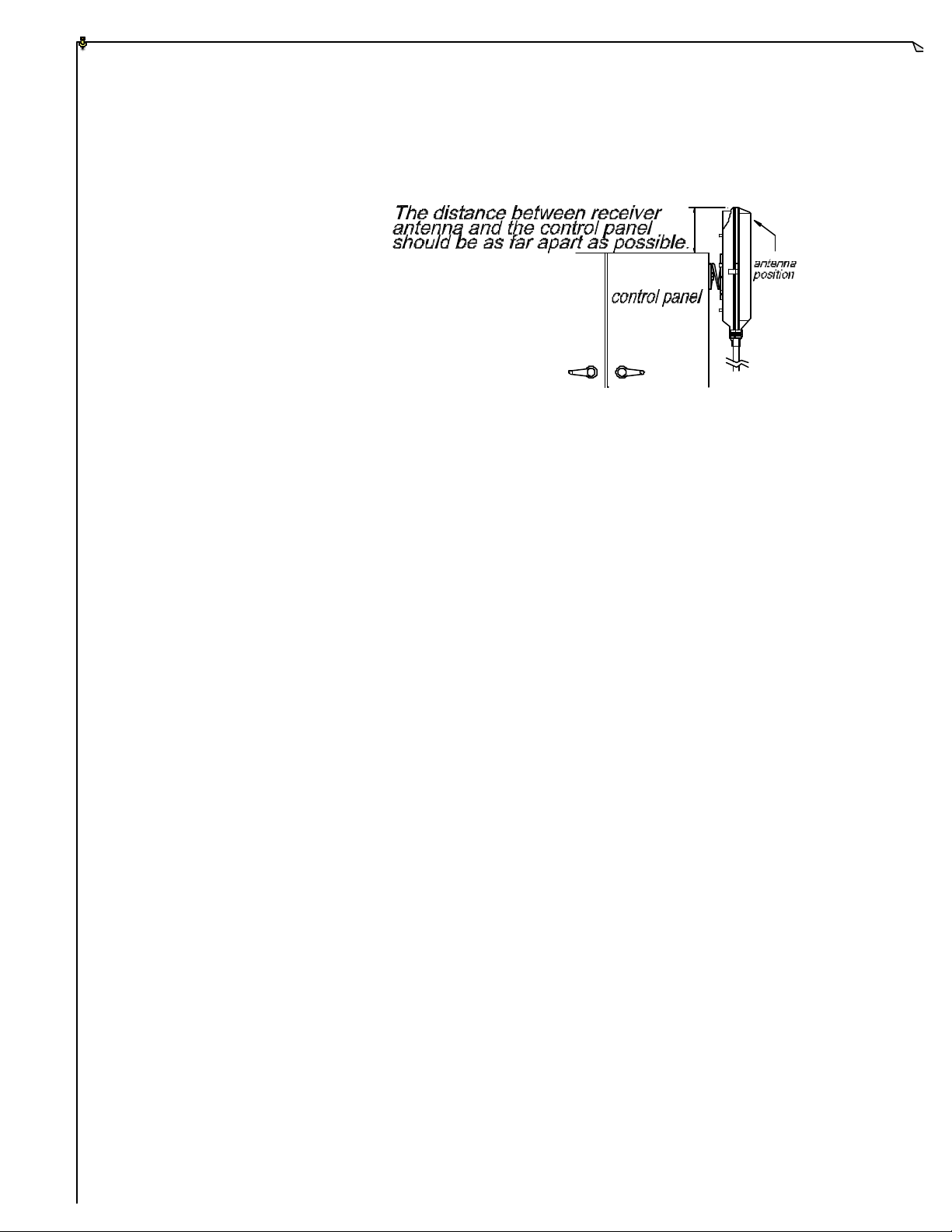
5. The distance between the antenna and the control panel should be as far apart as
possible (see diagram next page).
6. Drill a hole on the control panel (10.5mm)
7. Tightened the two bolt nuts provided.
8. If the control panel has a plastic surface, extended grounding wire should be used.
9. For system wiring, please refer to the output contact diagram on page 12~14 or on the
receiver enclosure.
10. Ensure all wiring is correct and safely secured and all screws are fastened.
17
Page 18
8.3 System Testing
1. Connect the power source to the receiver and test the operation of each function to
ensure it operates in the same manner as the pendant controller.
2. Ensure the receiver MAIN can be properly controlled by the remote control.
3. Ensure the limit switches on the equipment that limit all travels are working properly.
4. Ensure the pendant controller is located in a safe location where it would not interfere
with remote operation.
18
Page 19

9.
TRANSMITTER OPERATION
1. Make sure the (2) alkaline batteries are installed correctly. Do make sure to use alkaline
type batteries for longer operating time between battery replacements.
2. Turn “on” the power switch located on the top left hand corner of the transmitter unit (see
diagram next page). Immediately after turning “on” the transmitter unit, the status LED
indicator located at the center of the power switch will display a green light for up to 1.5
seconds, do make sure that the red EMS pushbutton is in its elevated position.
If the status LED displays a red blinking light (ON 0.1 second and OFF 2.0 seconds)
or no light at all, then you must replace a set of new batteries before operation. If the red
blinking light is ON 2.0 seconds and OFF 0.1 second, the transmitter unit will
deactivates itself (locked) due to a jammed or defected pushbutton contact. This important
safety feature is designed to prevent unexpected crane movement at system start up caused
by a defected pushbutton contact.
After transmitter self-diagnosing procedure is completed without any problems detected
(within 1 second), all transmitter key functions and the receiver MAIN will be activated.
3. Alpha 540T/560T model When the transmitter unit is turned “on” to begin work, the
LED-I will light up to indicate only the main hoist and/or trolley is activated. If you want to
activate the auxiliary hoist and/or trolley, press the "Select" pushbutton, and the LED
display will now switched from LED-I to LED-II to indicate that only the auxiliary hoist
and/or trolley is activated. Press "Select" again to have both main and auxiliary hoist
and/or trolley activated at the same time (both LED-I and LED -II lit). To switch back to the
main hoist and/or trolley activation, just press the "Select" pushbutton once again. (please
refer to section 3.3 on page 6)
Every time when the transmitter unit is turned “off” and then “on” again, the "Select "
setting will resets itself to LED-I (back to main hoist and/or trolley active)
4. Alpha 540T/560T model "Select" setting can not be changed while other command
pushbuttons are in use (command pushbuttons pressed). To insure maximum safety,
"select" settings (I, II, I&II) can only be changed when all command pushbuttons are in
their neutral position (command pushbuttons not pressed).
19
Page 20
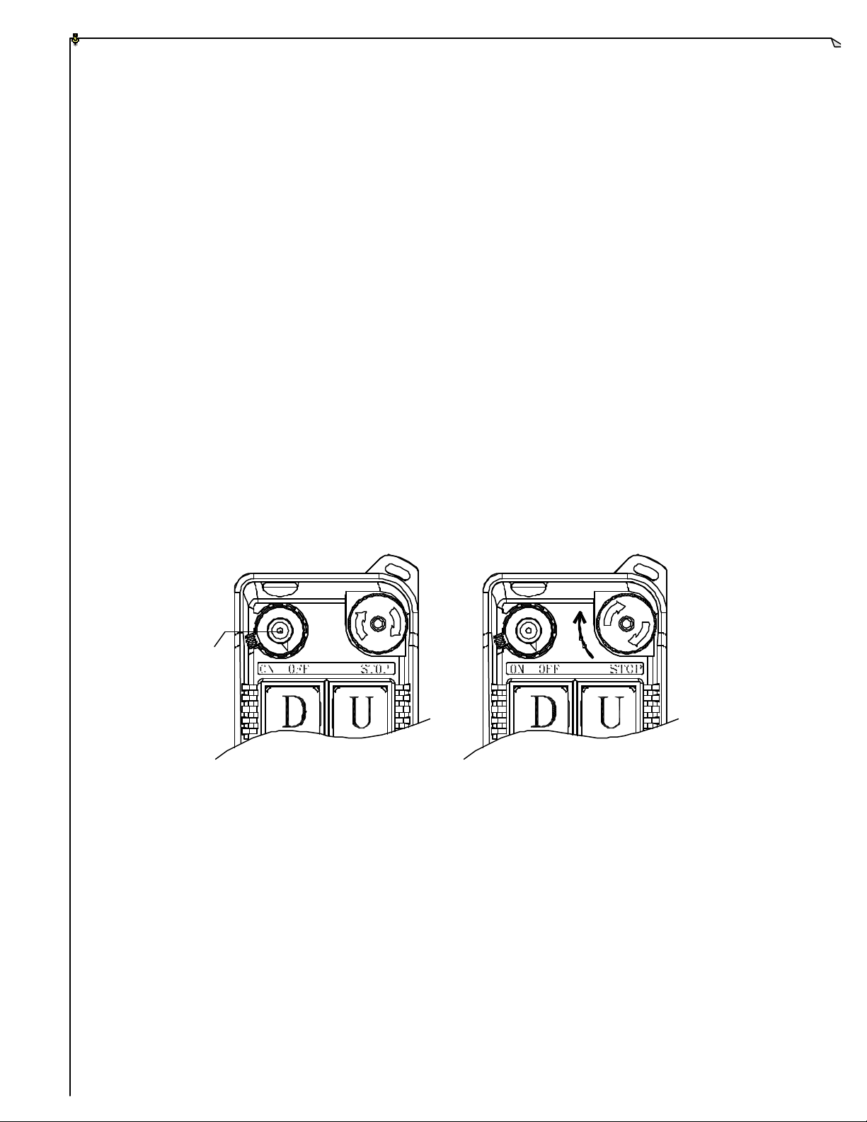
5. In case of an emergency, press down the red EMS pushbutton will immediately deactivates
the receiver MAIN. When the EMS pushbutton is activated, the status LED on the
transmitter unit will display a red blinking light to indicate EMS activation (ON 0.5
second and OFF 0.5 second). To reactivate the system again, turn the EMS pushbutton
clockwise so that the red cap will elevate to its non-active position. Then turn the
transmitter power switch “off” and then “on” again to activate all transmitte r key functions
and the receiver MAIN. As for the Alpha 540T and 560T models, to reactivate the system
after EMS reset, just press any command pushbutton (please refer to JP1 setting on page 15
and 16).
6. Please note that conflicted movements are inte rlocked to one another for safety purpose.
Pressing conflicted commands at the same time will result in a non-transmission.
LED DISPLAY
20
Page 21
10.
the receiver and
the transmitter will identify the RF
light or no light at all, then turn the
TROUBLE SHOOTING
Should the operator find the equipment not operating normally, please check the chart below for
simple trouble shooting steps.
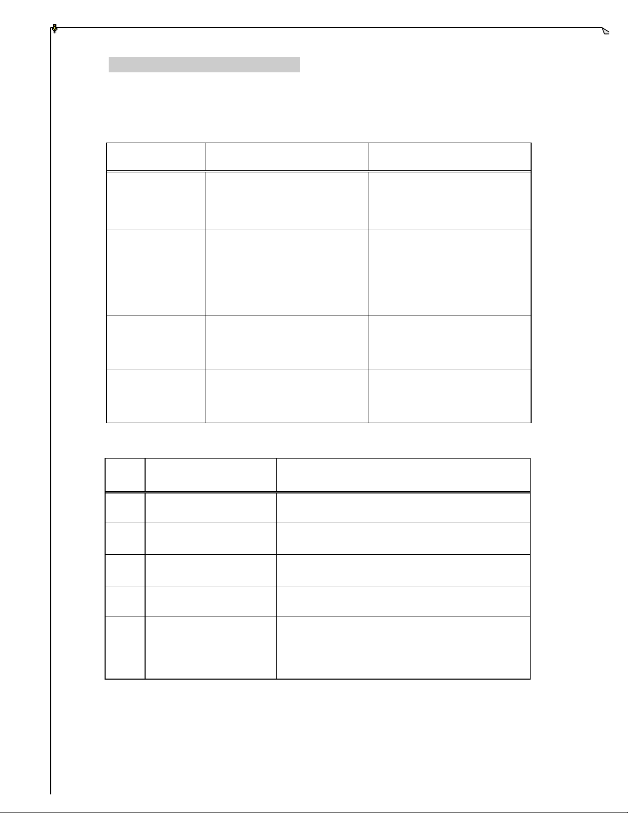
SYMPTOM REASON SOLUTION
Transmitter does not
communicate to
Receiver System Status LED Display (please refer to Fig. 11 on page 10).
receiver.
Transmitter does not
communicate to
receiver.
No power to the
receiver (AC power
indicator on the
receiver unit not lit).
Outputs do not
operate correctly.
TYPE
Transmitter and the receiver are
not on the same RF channel (SQ
lamp not lit) or ID code.
Low or no transmitting power
from the transmitter unit.
Blown fuse or no input power
Receiver configuration is not set
properly or output wiring is
LED INDICATION
(Red)
connection.
incorrect.
Ensure the correct transmitter is in
use. The labels on
channel and ID code in use.
Turn “on” the transmitter and with
EMS in its elevated position. If
the status LED shows blinking red
power “off” and replace the two
alkaline AA batteries.
Ensure power input to the receiver
unit is correct. If power indicator
(AC) is still not lit, please check
the receiver for any burned fuse.
Please refer to section 6 and 7 to
ensure receiver is correctly wired
and configured for your
application.
REASON
1 Constant red light.
2
3 Dim or no light. Under-voltage, check the main power supply.
4
5
6.
ON 1.0 second
OFF 1.0 second
ON 2.0 seconds
OFF 0.1 second
ON 0.1 second
OFF 2.0 seconds
ON 0.1 second
OFF 0.1second
EEPROM error, manufacture repr ogramming
required.
Incorrect ID code, please readjust accordingly.
System error, manufacture reprogramming required.
System normal with transmitter pushbutton either in
neutral or in transmitter power “off” position.
System normal with transmitter pushbutton in
non-neutral position (pressed).
21
Page 22

11.
SYSTEM SPECIFICA TION
Transmitter Unit
Frequency Range : 301 MHz
Transmitting Range : 150 feet
Hamming Distance : 4
Channel Spacing : 25KHz
Frequency Control : Quartz Crystals
Frequency Drift : < 5ppm @ -20 ~ +70
Frequency Deviation : < 1ppm @ 25
Spurious Emission : - 50dB
Transmitting Power : ~1mW
Emission : F1D
Antenna Impedance : 50 ohms
Enclosure : IP-66
Source Voltage : 3.0 VDC (“AA” alkaline batteries X 2)
Current Drain : 10 ~ 20 mA
Operating Temp. : -20 ~ +70
Dimension (Alpha 500/520) : 134mm X 68mm X 30.5mm
Dimension (Alpha 540/560) : 166mm X 67.5mm X 30mm
Weight (Alpha 500/520) : 7.05oz. (include batteries)
Weight (Alpha 540/560) : 8.82oz. (include batteries)
22
Page 23

Receiver Unit
F requency Range : 301 MHz
Channel Spacing : 25KHz
Hamming Distance : 4
Frequency Control : Quartz Crystals
Frequency Drift : < 5ppm @ -20 ~ +70
Frequency Deviation : < 1ppm @ 25
Sensitivity : 0.4ìV
Antenna Impedance : 50 ohms
Data Decoder Reference : Quartz Crystals
Responding Time : 40mS (Normal)
Enclosure : IP-65
Source Voltage : 48~380 VAC, 50/60 Hz.
Power Consumption : 11VA
Operating Temp. : -20 ~ +70
Output Contact Rating : 250V @ 10A
Dimension : 310mm X 134mm X 72mm
Weight (Alpha 500/520) : 57.3oz. (include output cable)
Weight (Alpha 540/560) : 60oz. (include output cable)
23
Page 24

12.
PARTS LIST
1. TX Module/Encoder Board (Alpha 500) BEN50
TX Module/Encoder Board (Alpha 520) BEN52
TX Module/Encoder Board (Alpha 540S) BEN54S
TX Module/Encoder Board (Alpha 540A) BEN54A
TX Module/Encoder Board (Alpha 540T) BEN54T
TX Module/Encoder Board (Alpha 560S) BEN56S
TX Module/Encoder Board (Alpha 560A) BEN56A
TX Module/Encoder Board (Alpha 560T) BEN56T
2. RX Module (All models) BRX10S
3. Decoder/Relay Board (Alpha 500) BDR50
Decoder/Relay Board (Alpha 520) BDR52
Decoder/Relay Board (Alpha 540S) BDR54S
Decoder/Relay Board (Alpha 540A) BDR54A
Decoder/Relay Board (Alpha 540T) BDR54T
Decoder/Relay Board (Alpha 560S) BDR56S
Decoder/Relay Board (Alpha 560A) BDR56A
Decoder/Relay Board (Alpha 560T) BDR56T
4. Transmitter Enclosure (Alpha 500/520) BCT50
Transmitter Enclosure (Alpha 540S/560S) BCT54S
Transmitter Enclosure (Alpha 540A/560A) BCT54A
Transmitter Enclosure (Alpha 540T/560T) BCT54T
5. Receiver Enclosure (All models) BCR50
6. Pushbutton (Dual speed) B50001
Pushbutton (Single speed) B50002
7. EMS Red Cap EMS01
8. Wrist Strap WS01
9. Pushbutton Rubber Boot PRB01
10. Direction labels (All types) DL01
11. Transformer (48 VAC) T48V
Transformer (110~120 VAC) T120V
Transformer (220~230 VAC) T230V
Transformer (380 VAC) T380V
12. Contact Relay RLY01
24
 Loading...