

Fomotech Alpha 3000, Alpha 3000D Series, Alpha 3000F2, Alpha 3000F Series, Alpha 3000D2 Series Manual
...
1
TTA
ABBLLEE
O
OFF
C
C
O
O
N
NTTEE
N
NTTSS
1. INTRODUCTION ....................................................................................................... 2
2. SAFETY INSTRUCTION ............................................................................................. 3
3. TRANSMITTER ILLUSTRATION
3.1 Alpha 3000F Models External Assembly ............................................................. 4
3.2 Alpha 3000F Models Internal Assembly ............................................................. 5
3.3 Alpha 3000D Models External Assembly ............................................................. 6
3.4 Alpha 3000D Models Internal Assembly ............................................................. 7
4. RECEIVER ILLUSTRATION
4.1 External Assembly (All Models) ......................................................................... 8
4.2 Alpha 3000F Models Internal Assembly ............................................................. 9
4.3 Alpha 3000D Models Internal Assembly ............................................................. 10
5. OUTPUT CONTACT DIAGRAM
5.1 Alpha 3000F2 Output Contact ............................................................................. 11
Page
5.2 Alpha 3000F3 Output Contact ............................................................................. 12
5.3 Alpha 3000D2 Output Contact ............................................................................. 13
5.4 Alpha 3000D3 Output Contact ............................................................................. 14
6. SYSTEM CONFIGURATIONS
6.1 Jumper Settings ................................................................................................... 15~17
6.2 Security ID Code Settings ..................................................................................... 18~19
6.3 Frequency (RF) Channel Settings ....................................................................... 19~20
6.4 How to Change the Transmitter Channels.............................................................. 20~22
6.5 Frequency (RF) Channel Table ........................................................................... 23
6.6 Pushbutton Contact Settings ................................................................................. 24
6.7 Voltage Settings ..................................................................................................... 25
6.8 Steps to Change the Frequency Band ..................................................................... 26
6.9 Steps to Change the Transmitting Power................................................................. 27
7. RECEIVER INSTALLATION
7.1 Preparation for Installation ................................................................................... 28
7.2 Step-By-Step Installation ....................................................................................... 28
7.3 System Testing ....................................................................................................... 29
8. TRANSMITTER OPERATION ................................................................................... 30~31
9. TROUBLE SHOOTING ............................................................................................... 32
10. SYSTEM SPECIFICATION ......................................................................................... 33
11. PARTS LIST ................................................................................................................. 34

2
11.. IINNTTRROODDUUCCTTIIOONN
The Alpha 3000 series are highly durable, reliable, and safe industrial radio remote control system.
The versatile features of the Alpha 3000 series permit their usage in many different radio remote
control applications that required 2-step or 3-step pushbutton controls. The system can be used to
control tower cranes, factory cranes, monorail systems, multiple hoists, trolleys, mining equipment,
building construction equipment, automatic control systems, and many others.
The Alpha 3000 radio remote control systems incorporate numerous redundant safety circuits that
guaranty maximum security and ensure the system is resistant to outside interference. The major
features of the Alpha 3000 series are as follow:
* The system uses advanced 16+1bit microprocessor control with highly evolved software that has
redundant error checking and correcting capabilities to ensure 100% error-free transmission,
decoding, and control of all output relays. This highly evolved software includes CRC (cyclical
redundancy check codes) and Hamming Codes (error recovery) programming.
* To insure maximum operating safety, the Alpha 3000 system incorporates numerous important
safety features. Some of these built-in safety features include transmitter pushbutton
self-diagnosing during initial startup, transmitter low-voltage detection and warning, receiver
self-diagnosing, and MAIN deactivation when transmitter is in sleep mode, when strong RF
interference is detected, and when the transmitter is out of receiving range.
* The transmitter encoder and receiver decoder both utilize advanced microprocessor control. The
availability of 65,536 sets of unique ID codes + 63 distinct RF channels will ensure that only
commands from the matching control transmitter can be carried out without any interference
from other radio systems.
* For added safety, the system also incorporates special type of safety MAIN relay. If the safety
MAIN relay becomes defective (fails to open or close during operation), it will signal the central
system to shut down immediately to avoid the possibility of any accidents occurring.
* 63 sets of user-adjustable receiving RF channels via simple dip-switch settings.
* 100% waterproofed transmitter and receiver enclosures (IP65 rated), including the battery
compartment.
Each Alpha 3000 series radio remote control system consists of a water-resistant IP65 handheld
transmitter and receiver. The transmitter casing is molded using industrial strength composite
materials (Nylon + Fiberglass) which are impervious to dust, water, oil, acids, alkaline, heat, sunlight
and as well as being resistant to deformation due to long term use in harsh environments. The
industry’s best 2-step & 3-step pushbuttons are also constructed from industrial strength composite
materials with a minimum of up to one million press cycles. For power savings, the transmitter is
designed with an ultra high efficiency power saving circuit that requires only four “AA” size alkaline
batteries for more than 200 hours of continuos operation between battery replacements.

3
22.. SSAAFFEETTYY IINNSSTTRRUUCCTTIIOONN
The Alpha 3000 system is relatively simple to use, however, it is very important to observe the proper
safety procedures before, during, and after operation. When used properly our Alpha 3000 series
remote controls will enhance safety, productivity and efficiency in the workplace.
The following procedures should be strictly followed:
1. Check the transmitter casing and pushbuttons daily. Should any damage that could inhibit the
proper operation of the transmitter be found the unit should be immediately removed from
service.
2. The transmitter voltage should be checked on a daily basis. If the voltage is low (red status light
blinking - refer to page 28), the four “AA” alkaline batteries should be replaced.
3. The red emergency stop button (EMS) should be checked at the beginning of each shift to ensure
it is in proper working order and the Stop command is being received.
4. In the event of an emergency, push down the emergency stop button (EMS) immediately to
deactivate the transmitter power and the receiver MAIN relay. Then turned the power “off” from
the main power source to the crane or equipment.
5. The transmitter power key should be pulled “off” after each use and should never leave the
transmitter in the power “on” position when the unit is unattended.
6. Do not use the same RF channel and ID code as any other system in use at the same facility or
within distance of 30 meters.
7. Ensure the shoulder strap is worn at all time during operation to avoid accidental damage to the
transmitter.
8. Never operate a crane or equipment with two transmitter units at the same time with the same RF
channel and ID code.
Caution!
Improper Storage of your Spare Transmitter is a Safety Hazard! During the initial installation
of your remote control system the spare (second) transmitter should be tested to confirm that it
is functioning properly and then the batteries must be removed and the transmitter stored in a
secured place. Failure to follow this safety procedure can result in the inadvertent operation of
your crane or hoist by unauthorized personnel resulting in serious injury or death!

4
33.. TTRRAANNSSMMIITTTTEERR IILLLLUUSSTTRRAATTIIOONN
33..11 AAllpphhaa 33000000FF MMooddeellss EExxtteerrnnaall AAsssseemmbbllyy
START
1
2
4
5
6
7
8
9
10
11
12
13
14
15
16
17
3
AUX
(Transmitter Front View) (Transmitter Back View)
1. Transmitter Unit 9. Pushbutton #1 (U or ↑)
2. Status LED Display* 10. Pushbutton #3 (E or →)
3. Spare Power Key 11. Pushbutton #5 (N or ↗)
4. Pushbutton #2 (D or ↓) 12. Pushbutton #7 (START/AUX)
5. Pushbutton #4 (W or ←) 13. Warning Label
6. Pushbutton #6 (S or ↙) 14. Shoulder Strap Ring
7. Emergency Stop Button (EMS) 15. System Information
8. Power Key Switch 16. Battery Cover
17. FCC/IC Label
* Please refer to page 25 for transmitter Status LED display information
5
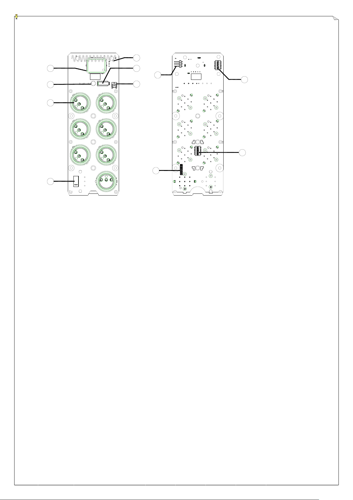
33..22 AAllpphhaa 33000000FF MMooddeellss IInntteerrnnaall AAsssseemmbbllyy
6
7
11
1
4
3
2
9
1
2
3
4
5
6
7
8
8
5
10
1 2 3 4
5
6
7
8
(PCB Front View) (PCB Back View)
1. RF module 6. Power ON/OFF Micro-Switch
2. Status LED Display 7. Battery Power Connector
3. 1, 2 or 3-Step Pushbuttons 8. RF test pin
4. Emergency Stop Button (EMS) 9. ID Code Soldering Slot (1st ~ 8th digit)
5. Internal Antenna 10. Channel Dip-switch
11. ID Code Dip-switch (9th~16th digit)
6
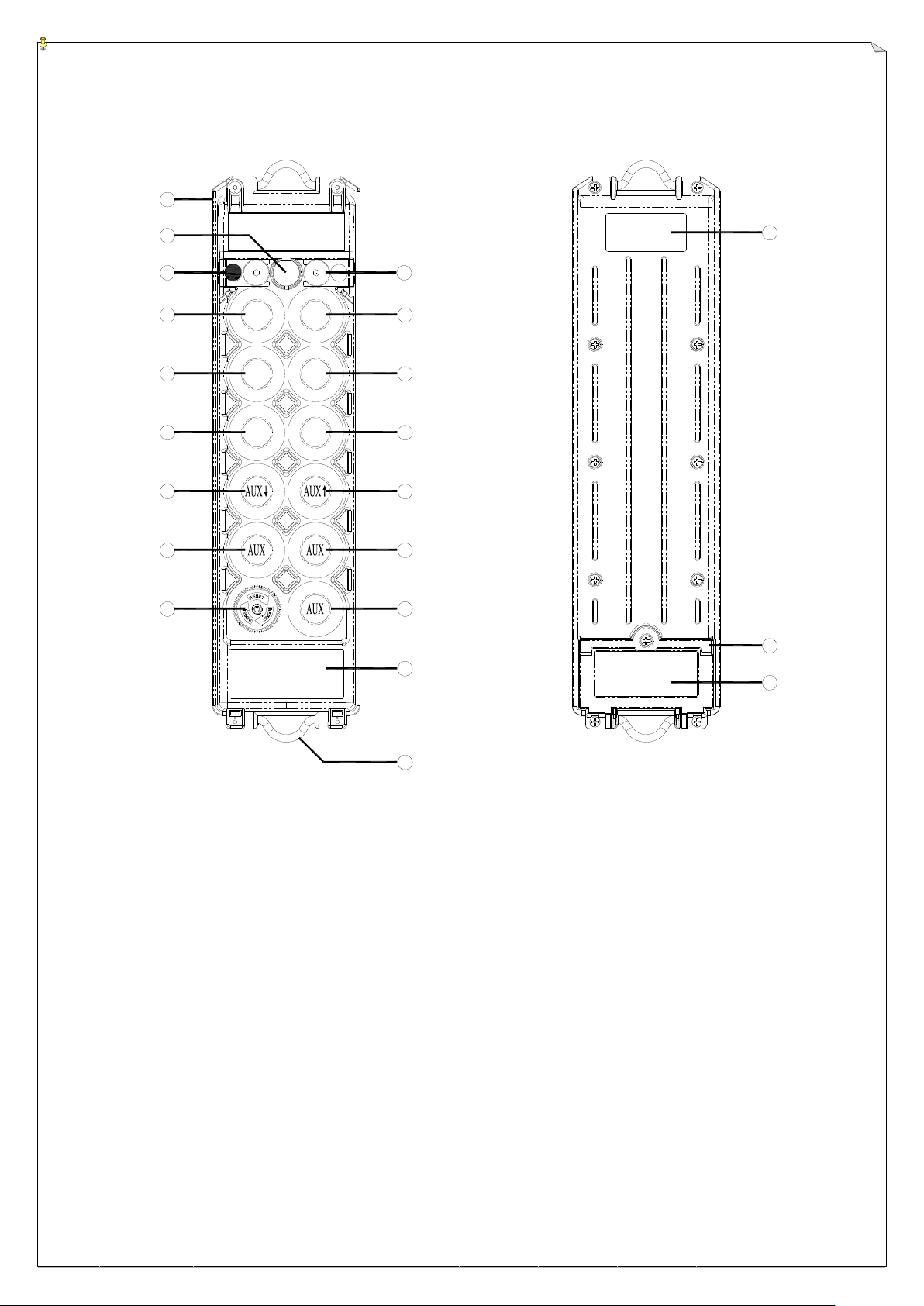
33..33 AAllpphhaa 33000000DD MMooddeellss EExxtteerrnnaall AAsssseemmbbllyy
1
U
2
3
4
11
12
5
6 13
7
14
8
15
9 16
17
D
W
E
N
S
18
10
19
20
21
(Transmitter Front View) (Transmitter Back View)
1. Transmitter Unit 11. Pushbutton #1 (U or ↑)
2. Status LED Display* 12. Pushbutton #3 (E or →)
3. Spare Power Key 13. Pushbutton #5 (N or ↗)
4. Pushbutton #2 (D or ↓) 14. Pushbutton #7 (AUX or AUX ↑)
5. Pushbutton #4 (W or ←) 15. Pushbutton #9 (AUX or AUX →)
6. Pushbutton #6 (S or ↙) 16. Pushbutton #11 (START/AUX)
7. Pushbutton #8 (AUX or AUX ↓) 17. Warning Label
8. Pushbutton #10 (AUX or AUX ←) 18. Shoulder Strap Ring
9. Emergency Stop Button (EMS) 19. System Information
10. Power Key Switch 20. Battery Cover
21. FCC/IC Label
* Please refer to page 25 for transmitter Status LED display information
7
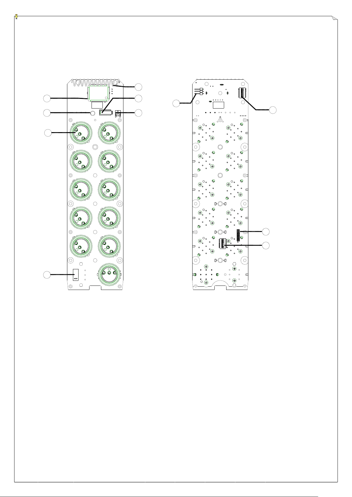
33..44 AAllpphhaa 33000000DD MMooddeellss IInntteerrnnaall AAsssseemmbbllyy
1
3
2
4
7
6
5
11
10
8765
4
3
2
1
8
9
8
7
6
5
4321
(PCB Front View) (PCB Back View)
1. RF module 6. Power ON/OFF Micro-Switch
2. Status LED Display 7. Battery Power Connector
3. 1, 2 or 3-Step Pushbuttons 8. RF test pin
4. Emergency Stop Button (EMS) 9. Channel Dip-switch Slot (1st ~ 8th digit)
5. Internal Antenna 10. ID Code Soldering
11. ID Code Dip-switch (9th~16th digit)
8
5
6
2
3
1
4
7
44.. RREECCEEIIVVEERR IILLLLUUSSTTRRAATTIIOONN
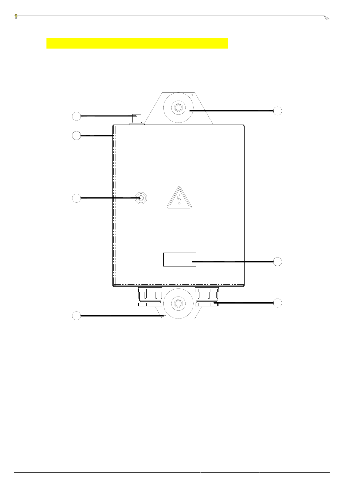
44..11 EExxtteerrnnaall AAsssseemmbbllyy ((AAllll MMooddeellss))
(Alpha 3000 Models Receiver External View)
1. Antenna Seat 4. External Grounding Hole
2. Receiver Enclosure 5. Rubber Shock Absorber
3. Key Lock 6. System Information
7. Cable Gland/Cord Grip
9
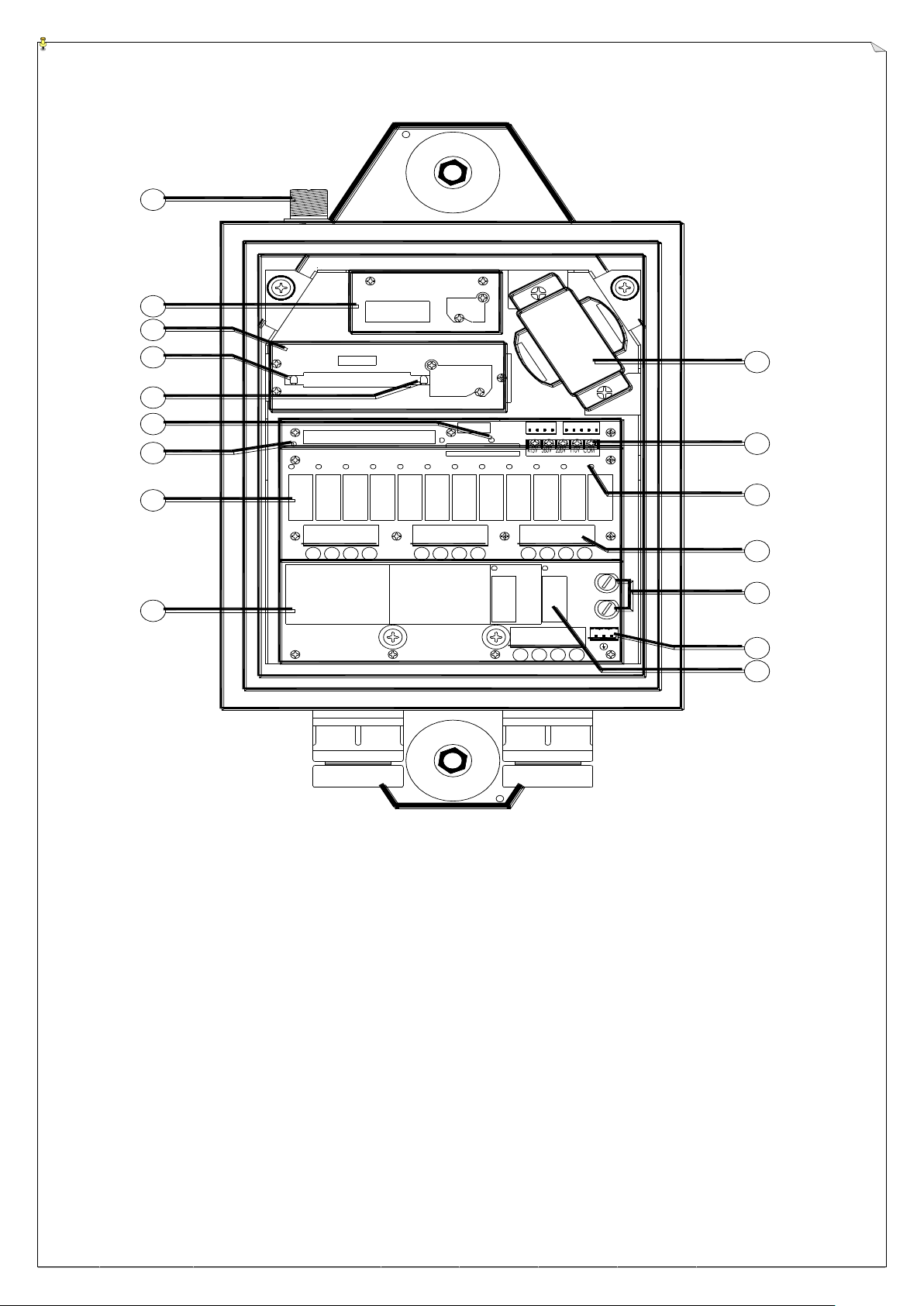
44..22 AAllpphhaa 33000000FF MMooddeellss IInntteerrnnaall AAsssseemmbbllyy
11
~
7
12
13
14
15
16
6
5
4
K1K2K3
K4
K5K6K7
K8 K9
K10 K11 K12
K24
K23
K22K21
~
1
2
3
8
9
10
(Alpha 3000F2 & F3 Models Receiver Internal View)
1. Antenna Seat 9. Bottom Relay Board
2. Receiving RF Module 10. Power Transformer
3. Decoder Module 11. Input Voltage Selector Seat
4. Decoder Module Power Display 12. Contact Relay LED Display
5. Receiver Status LED Display* 13. Terminal Block
6. SQ Status LED Display* 14. Power Fuses (1.0A)
7. Power (AC) LED Display 15. AC Power Input
8. Upper Relay Board 16. MAIN Contact Relay
* Please refer to page 27 for Receiver and SQ display information
10
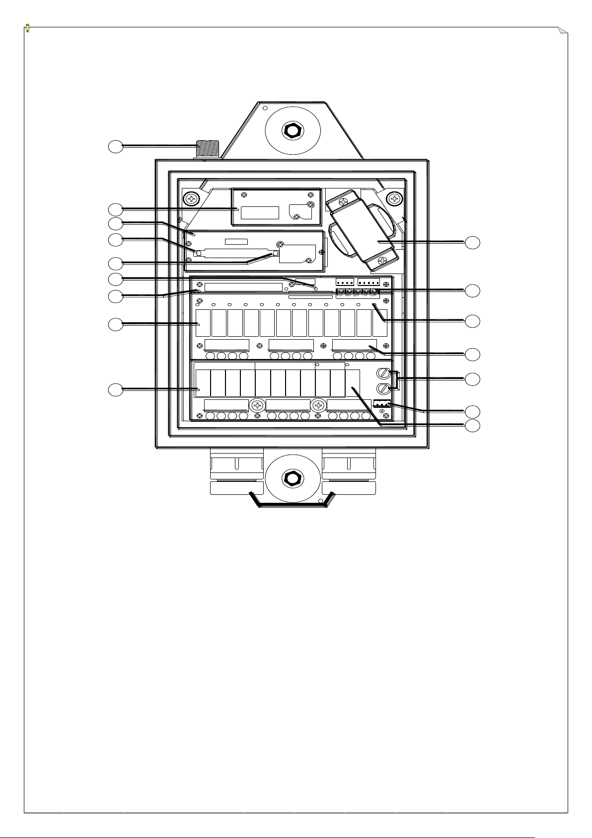
44..33 AAllpphhaa 33000000DD MMooddeellss IInntteerrnnaall AAsssseemmbbllyy
K21
~
1
2
3
8
9
10
11
K24
K10
K9K6
K5
K2
K1
~
7
12
13
14
15
16
6
5
4
K17 K18
K3
K4
K7
K8
K11
K12
K16K15 K19 K20
K22
K23
K14
K13
(Alpha 3000D2 & D3 Models Receiver Internal View)
1. Antenna Seat 9. Bottom Relay Board
2. Receiving RF Module 10. Power Transformer
3. Decoder Module 11. Input Voltage Selector Seat
4. Decoder Module Power Display 12. Contact Relay LED Display
5. Receiver Status LED Display* 13. Terminal Block
6. SQ Status LED Display* 14. Power Fuses (1.0A)
7. Power (AC) LED Display 15. AC Power Input
8. Upper Relay Board 16. MAIN Contact Relay
* Please refer to page 27 for Receiver and SQ display information
11
5.
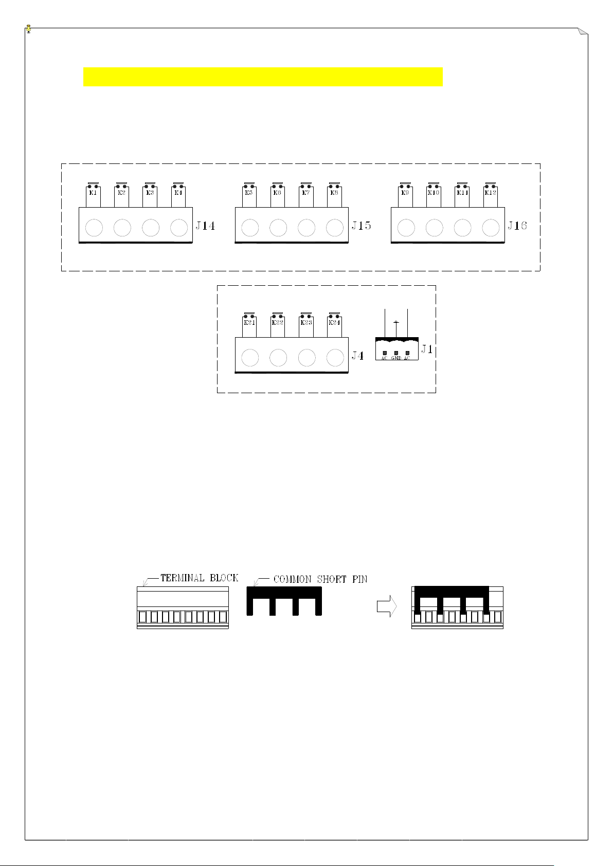
55..11 AAllpphhaa 33000000FF22 OOuuttppuutt CCoonnttaacctt
UPPER RELAY BOARD
BOTTOM RELAY BOARD
U1
U2 E1
E2
N1
N2D2
D1
W1
W2
S1 S2
ID
MAIN
AUX
OUTPUT CONTACT DIAGRAM
Note A: AUX output contact represents the 7th pushbutton on the transmitter (START/AUX), which
Note B: The preprinted output contact markings on the relay boards below the terminal blocks are
Common shorting pin illustrated above can be used rather than “daisy chaining” wiring for the
common.
can be used for lights, horn, or other types of applications (refer to section 6.6 on page 24).
intended for Alpha 3000F3 and Alpha 3000D3 models. If your system is an Alpha 3000F2
or an Alpha 3000D2 model, please ignore the preprinted markings and connect the wires
according to the diagram above.
Terminal Block and Common Shorting Pin Assembly
 Loading...