

Follett U155R400A, U155BR800A, U155BR800W, U155BXR800A, U155BXR800W Installation, Operation And Service Manual
Page 1
U155 Series
Ice and Beverage Dispensers
Order parts online
www.follettice.com
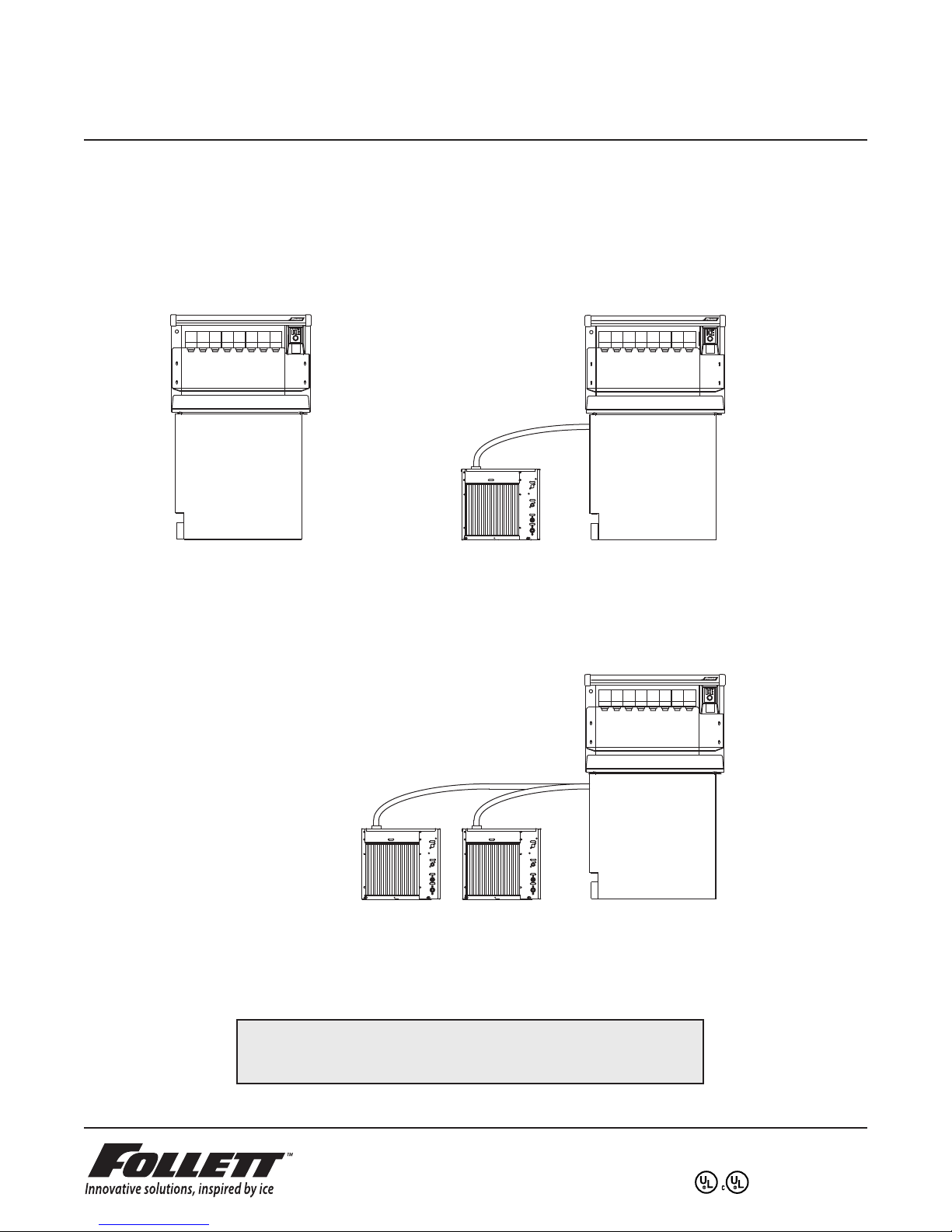
Manual load unit
Model U155, U155X
Model U155B, U155BX
Installation, Operation and Service Manual
Automatic load unit
with one icemaker
Model U155R400A/W, U155XR400A/W
Model U155BR400A/W, U155BXR400A/W
Automatic load unit
with two icemakers
Model U155R800A/W, U155XR800A/W
Model U155BR800A/W, U155BXR800A/W
Following installation, please forward this manual
to the appropriate operations person.
801 Church Lane • Easton, PA 18044, USA
Toll free (800) 523-9361 • (610) 252-7301
Fax (610) 250-0696 • www.follettice.com
208598R05
Page 2

This page intentionally left blank.
2
Page 3
Table of contents
Welcome to Follett Corporation
Important cautions
Speci cations
Installation
Installing dispenser in counter
Electrical connections
Field wiring diagrams
Connecting beverage lines
Installing optional icemaker
Operation
How the dispenser works
Cleaning
Service
Dispense chute cover removal
Auger motor assembly removal
Gate assembly removal
Auger and auger tube removal
Dispenser wheel removal
Wiring diagrams
Troubleshooting
Replacement parts
4
4
5
7
7
8
8
9
9
10
10
11
13
13
13
13
13
13
14
15
17
Follett Corporation
Equipment Return Policy
Follett equipment may be returned for credit under the following conditions:
1. The equipment is new and unused.
2. A return authorization number has been issued by customer service.
3. Follett receives the equipment at the factory in Easton, PA within 30 days of the issue of the return authorization number.
4. The equipment must be returned in Follett packaging. If the packaging has been damaged or discarded, Follett will forward, at the customer’s
expense, new packaging.
Note: Return freight charges are the responsibility of the customer. If equipment is returned and is damaged because of improper packaging, Follett
Corporation will not be held responsible.
Credit will be issued when:
The equipment has been inspected by Follett and deemed suitable to be returned to stock.
Note: A 15% restocking charge will be deducted from the credit. If the cost to return the product to stock exceeds 15%, the actual cost will be
deducted.
3
Page 4
Welcome to Follett
Follett equipment enjoys a well-deserved reputation for excellent performance, long-term reliability and
outstanding after-the-sale support. To ensure that this dispenser delivers that same degree of service, we ask that
you take a moment to review this manual before beginning the installation of the dispenser. Should you have any
questions or require technical help at any point, please call our technical service group at (800) 523-9361 or
(610) 252-7301.
Before you begin
After uncrating and removing all packing material, inspect the equipment for concealed shipping damage. If
damage is found, notify the shipper immediately and contact Follett Corporation so that we can help in the ling
of a claim, if necessary.
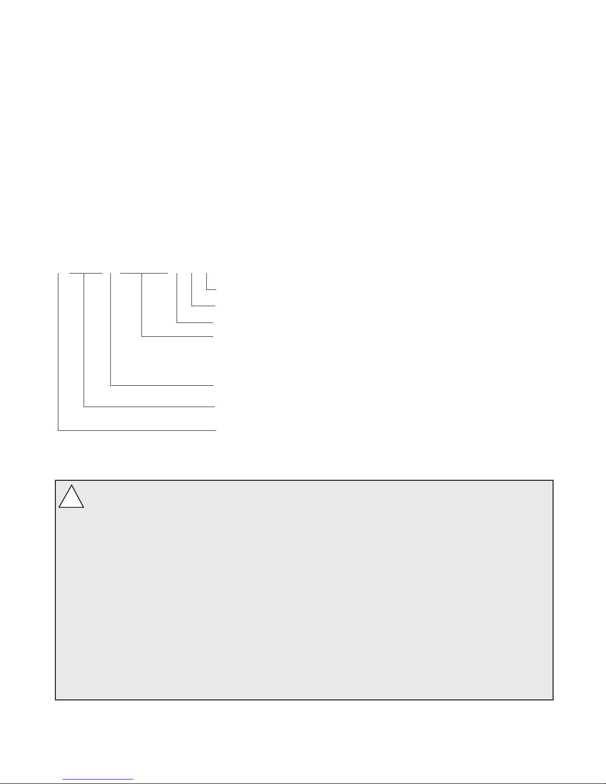
Check your paperwork to determine which model you have. Follett model numbers are designed to provide
information about the type and capacity of Follett ice dispensing equipment. Following is an explanation of the
different model numbers in the U155 series.
U155BR400AXR
Ice dispense chute location – R = right side, L = left side
Presence of an X = 10 soda valves
Condenser type – A = air-cooled, W = water-cooled
Remote icemaker(s) capacity and refrigerant – 400 = 400 lbs (181kg)/day, R404A
800 = 800 lbs (363kg)/day, R404A
absence of = manual ll unit
B = beverage bath equipped. Absence of a B = no integral beverage cooling
Approximate manual load storage capacity in lbs
Dispenser con guration – U = undercounter
Important cautions
!
Storage area of dispenser contains mechanical, moving parts. Keep hands and arms clear of
this area at all times. If access to this area is required, power to unit must be
disconnected rst.
Ice is slippery. Maintain counters and oors around dispenser in a clean and ice-free condition.
Ice is food. Follow recommended cleaning instructions to maintain cleanliness of delivered ice.
Always disconnect power before cleaning or servicing the dispenser.
Failure to remove all sanitizer may result in health hazard.
Follett manual load dispensers can accommodate most cube/cubelet ices up to 1" square, or Follett
compressed nugget ice. Crushed, ake, bagged, nugget or congealed ice cannot be used. Use of
these ices can jam dispenser and void warranty. Separate any “waffle-like” sections of cubes before
adding to dispenser. For ice compatibility questions, please call Follett customer service at
(800) 523-9361 or (610) 252-7301.
4
Page 5

Speci cations
Electrical
Each icemaker and dispenser require a separate circuit with electrical disconnect within 10 ft (6m). Equipment
ground required. Standard electrical – 115V, 60Hz, 1 phase. Maximum dispenser fuse – 15 amps, Maximum
icemaker fuse – 20 amps each.
Model Icemaker Dispenser
number amperage amperage
Single-sided models
U155, U155X 2.4 amps
U155B, U155BX 4.4 amps
U155R400A/W, U155R400A/WX 11.0 amps 2.4 amps
U155BR400A/W, U155BR400A/WX 11.0 amps 4.4 amps
U155R800A/W, U155R800A/WX 11.0 amps ea (2) 2.4 amps
U155BR800A/W, U155BR800A/WX 11.0 amps ea (2) 4.4 amps
Plumbing
Dispenser 3/4" PVC pipe nipple for bin drain
3/4" PVC pipe nipple for drain pan drain
1" ID hose for beverage bath drain
Beverage connections
1/4" ID syrup beverage hose
3/8" ID carbonated water beverage hose
3/8" ID plain water beverage hose
Note: Drains should be hard piped and insulated. Maintain at least 1/4" per foot (6mm per 304mm run)
slope on drain line run.
Water disconnect within 10 feet (3m) of dispenser is suggested for automatic load units.
Follett recommends use of a Follett water lter (part# 00130229) on icemakers connected
to automatic ll dispensers.
Icemaker (detailed speci cations may be found in icemaker installation manual
packed with icemaker)
3/8" OD push-in water in
3/4" MPT drain
3/8" FPT condenser inlet (water-cooled condenser only)
1/2" FPT condenser drain (water-cooled condenser only)
5
Page 6
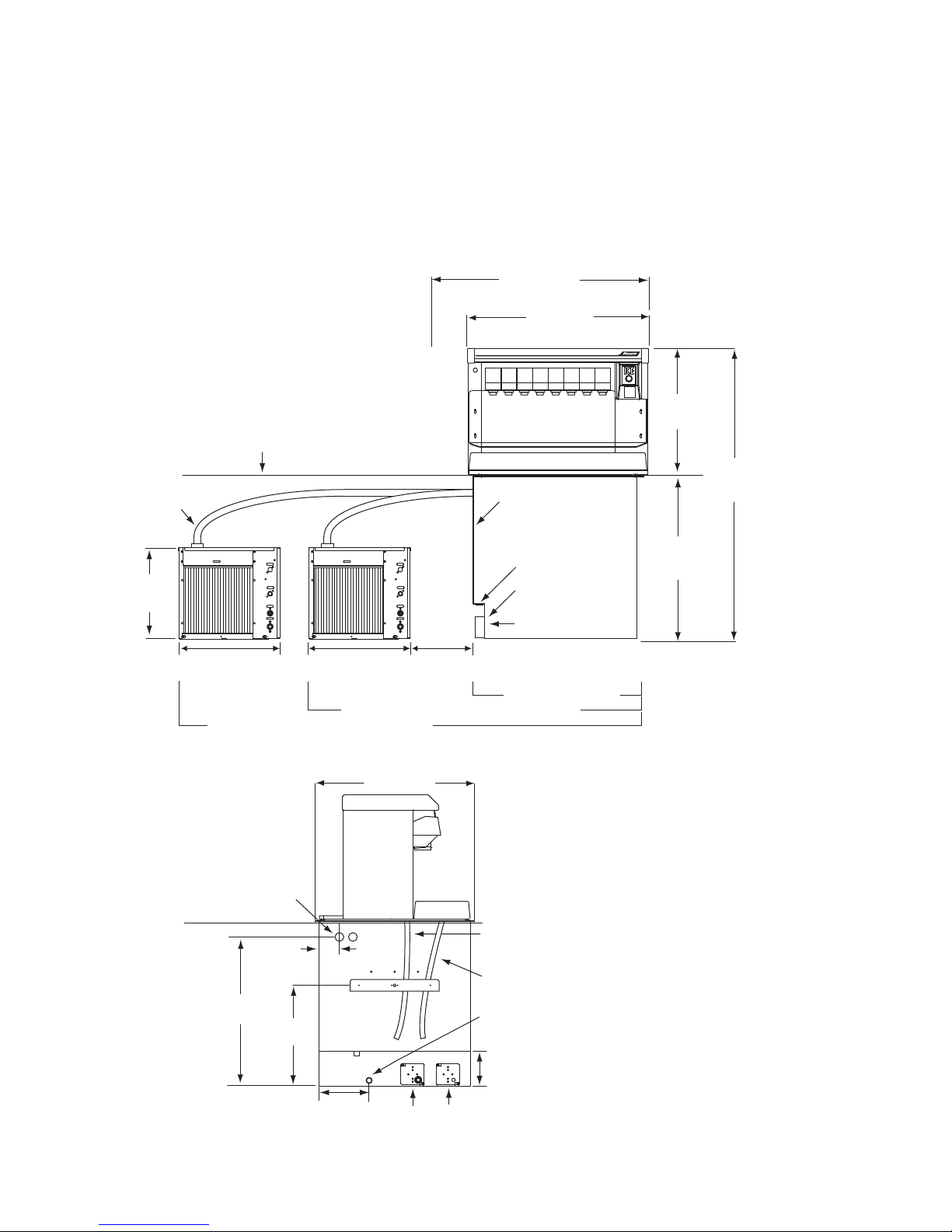
Dimensions and clearances
*DO NOT
CONNECT TO
DRAIN SYSTEM
6"
min
27.375"
(696mm)
ice transport
Side View
Front View
tube entrance
6"
(153mm)
25.8"
(656mm)
bin
signal
power
8.75"
(223mm)
3/4 PVC
slip joint
drain
3/4 PVC slip
joint drain
18.5"
(470mm)
beverage
waterbath
overflow
beverage
drain pan
drain
3.5"
(889mm)
37.25"
17"
(432 mm)
18.875"
(479mm)
18.875"
(479mm)
beverage line
air break*
electrical
connections
31.25"
(794mm)
21.75"
(553mm)
28"
(712mm)
counter top
ice
transport
tube
49.75"
(1264mm)
(8 valve unit)
(10 valve unit)
(947mm)
Manual load unit
Automatic load unit with 1 icemaker
Automatic load unit with 2 icemakers
12"
min
Required clearances
51" (1295mm) minimum above counter for installation if dispenser will be dropped into counter
36" (915mm) minimum above counter for all units after installation for auger cleaning and servicing
12" (305mm) minimum on side opposite ice chute for service
12" (305mm) minimum on ice chute side if ice transport tube enters this side
12" (305mm) minimum between dispenser side(s) and optional icemaker(s)
6
Page 7
Installation
Installing dispenser in counter
Note: All dispensers must be supported from below with supplied 6" - 9" (153 – 229mm) adjustable leg accessory,
or equivalent. Do not hang dispenser on ange.
All dispensers must be installed level in both directions to ensure proper operation.
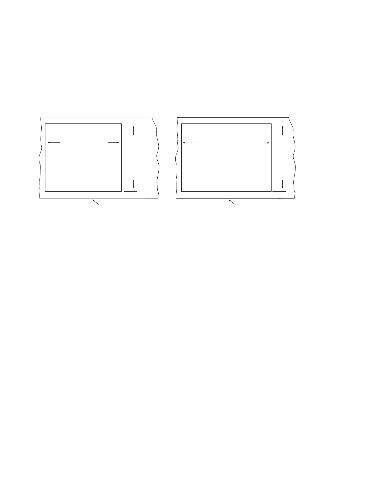
1. Check that dispenser location meets all requirements in this manual and cut counter as shown.
Plan View
units with up to 8 valves
counter cut-out
30.375"
(772mm)
+.125"
- .125"
+3 mm
- 3 mm
Front of counter
26.25"
+.125"
- .125"
(667mm)
+3 mm
- 3 mm
36.375"
(924mm)
+.125"
- .125"
+3 mm
- 3 mm
Plan View
units with 10 valves
counter cut-out
26.25"
+.125"
- .125"
(667mm)
+3 mm
- 3 mm
Front of counter
2. Place support blocks in cabinet to raise dispenser to a height of 12" (305mm)
3. Place dispenser in counter onto support blocks.
4. Attach adjustable legs to dispenser.
5. Remove support blocks and lower dispenser feet to oor.
6. Adjust legs for 1/8" (4mm) clearance between dispenser lip and countertop to verify there is no load on ange.
7. Apply a bead approximately 1/4" (6mm) in diameter of NSF-listed silicone sealant (Dow Corning RTV-732 or
equivalent) around perimeter of dispenser where it meets counter. Smooth sealant to a 1/8" (4mm) radius.
8. Install a PVC drain line with at least a 1/4" per foot (20mm per 1m) slope. Insulate drain line to prevent
condensation.
Note: Do not apply excessive heat if any sweating of ttings is necessary. Heat conduction through metal may
melt threads in plastic drain.
Do not reduce drain line size or tie drains together.
9. Make electrical connections in accordance with applicable wiring diagrams provided. Provide disconnects within
10 ft (3m) of dispenser and icemaker for servicing.
7
Page 8
Electrical connections
Model
U155, U155X,
U155B, U155BX
Electrical connection
Hard wiring of dispenser required
Circuit(s) required
115V, 60Hz, 1 phase
Max. fuse dispenser – 15 amps
U155R400A/W,
Dispenser power – hard wiring required
115V, 60Hz, 1 phase (2) circuits required
U155R400A/WX, U155BR400A/W,
U155BR400A/WX
Bin signal – cord and plug supplied
Icemaker – cord and plug supplied
Dispenser – 15 amps max. fuse size
Icemaker – 20 amps max. fuse size
on power and bin signal
U155R800A/W,
U155R800A/WX, U155BR800A/W,
Dispenser power – hard wiring required
115V, 60Hz, 1 phase (3) circuits required
U155BR800A/WX
Bin signal – cord and plug supplied
Icemaker – cord and plug supplied on
power and bin signal
Dispenser – 15 amps max. fuse size.
(2) icemakers – 20 amps max. fuse size
each
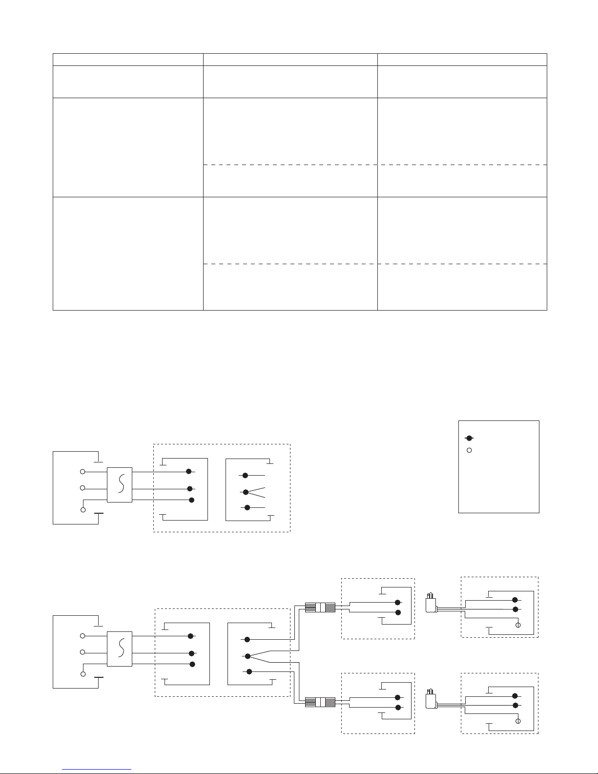
Field wiring diagrams
Note: Field wiring diagrams are intended to aid electricians or technicians in understanding how equipment
works. All eld wiring must be installed in accordance with all local and NEC codes.
Manual load models
Electric Power
Source
GND
W
B
GRN
X
15 AMP FUSED
DISCONNECT
Automatic load models
Electric Power
Source
GND
W
B
GRN
X
15 AMP FUSED
DISCONNECT
DISPENSER
LEFT JUNCTION BOX
W
B
GND
GRN
DISPENSER
LEFT JUNCTION BOX
W
B
GND
GRN
RIGHT JUNCTION BOX
BL
Y
RD
RIGHT JUNCTION BOX
BL
Y
RD
NOT
USED
ICEMAKER #1
(OPTIONAL)
LOWER JUNCTION BOX
ICEMAKER #2
(OPTIONAL)
LOWER JUNCTION BOX
B
W
W
B
ELECTRIC
POWER
SOURCE
ELECTRIC
POWER
SOURCE
LEGEND
WIRENUT FIELD
CONNECTIONS
EQUIPMENT
X
GROUND
B
BLACK
WHITE
W
GREEN
GRN
BL
BLUE
YELLOW
Y
RED
RD
UPPER JUNCTION BOX
GND
X
UPPER JUNCTION BOX
GND
X
W
B
GRN
W
B
GRN
8
Page 9
Connecting beverage lines
1
2
34
56
7
8910
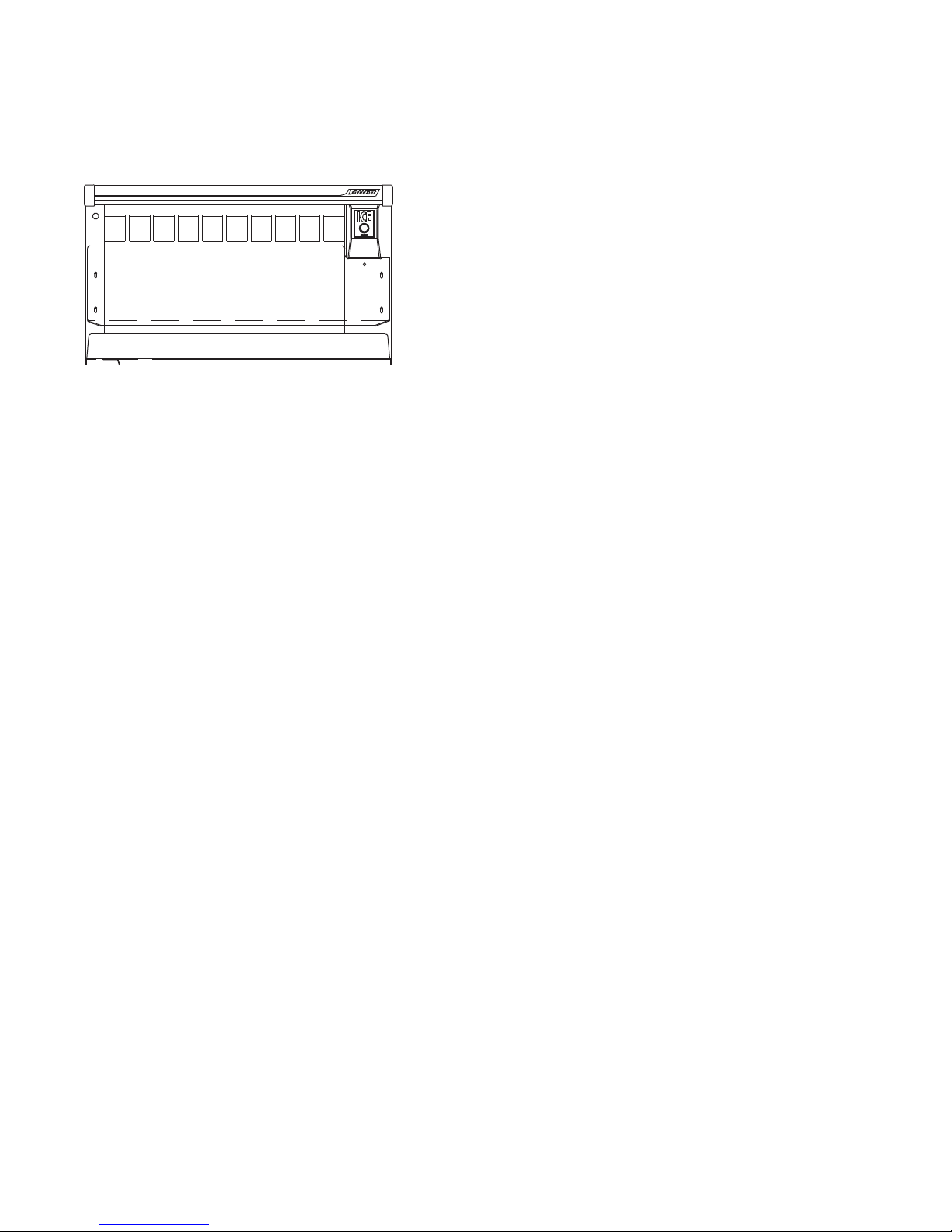
1. Connect syrup and water lines. Non-carbonated water line will be labeled “water”. Syrup lines are numbered
and correspond to the valves as shown in drawing(s) below. Valve one is always next to ice tower.
2. Clean and sanitize beverage lines in accordance with cleaning instructions.
Valve position #1 is always next to ice
tower. Right-hand unit shown.
Installing optional icemaker
Correct installation of remote icemaker(s) is critical to proper performance of icemaker. Refer to installation
manual packed with icemaker for important details on ice transport tube run, ventilation requirements and other
installation requirements. Failure to comply with instructions may void warranty.
To start up and operate dispenser
1. Follow detailed cleaning instructions in service manual before operating dispenser.
2. On units with Follett integral ice water bath beverage cooling (“B” models) only, slowly pour water into ice
water bath area to ll empty bath and submerge coils. Coils are submerged when water starts to ow out
over ow drain. DO NOT SPLASH WATER ON ELECTRICAL BOX. Once lled with water, add ice to bath
until ice covers top of waterbath.
3. For manual load units, remove front drain pan or rear lid and ll storage area with approved ice.
Note: Follett manual load dispensers can accommodate most cube/cubelet ices up to 1" square, or Follett
compressed nugget ice. Crushed, ake, bagged, nugget or congealed ice cannot be used. Use of these
ices can jam dispenser and void warranty. Separate any “waffle-like” sections of cubes before adding to
dispenser. For ice compatibility questions, please call Follett customer service at (800) 523-9361
or (610) 252-7301.
4. Turn power switch located on dispenser control box to ON position.
5. For automatic ll units, follow detailed instructions in icemaker installation section of installation manual, then
turn icemaker (bin signal) switch(es) located on dispenser control box to ON position and begin to make ice.
6. When dispenser has at least 6" (153mm) of ice in storage area, test operation.
9
Page 10
Operation
How the dispenser works
Follett’s dispensers are available in automatic load con gurations, fed from one or two Follett remote icemakers or
manual load con gurations (using ice from another source).
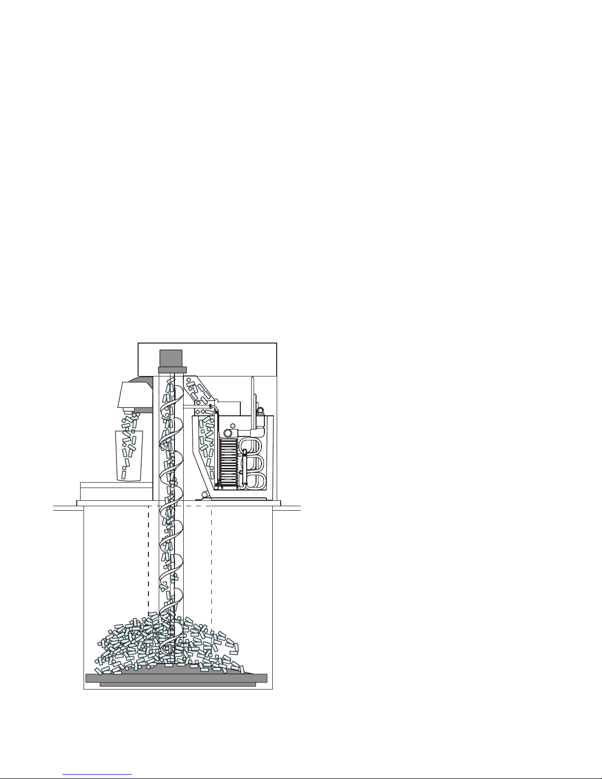
In all models, ice is stored below the counter in the dispenser storage area. When the dispense lever or button is
pushed, the dispense motors are activated. This causes the wheel assembly in the storage area to turn, moving
ice to the vertical auger assembly, which carries ice up to the dispense chute where it drops by gravity into the
container.
In automatic load units, ice is manufactured in either one or two Follett remote icemakers. These icemakers may
be located up to 20 ft (6m) away from the dispenser. Extruded ice is transported through a tube and pushed to the
storage compartment of the dispenser. When the bin is lled, a bin thermostat shuts the icemaker off to avoid
over lling of the bin. The icemaker will restart after 20 minutes if the bin is calling for ice.
Units with integral ice water bath beverage cooling are equipped with a waterbath timer circuit that activates the
waterbath pump for 35 minutes when ice lever or button is activated, or when the ice water bath warms up and
calls for more ice.
Ice movement
10
Page 11

Cleaning
Using solutions below, clean and sanitize storage area and beverage lines before starting unit and on a routine
basis as noted below.
Note: Always disconnect power before cleaning dispenser.
Do not run plastic parts through a dishwasher.
Solution A: Combine 1 oz (250ml) bleach with 2 gal (8L) hot water or use Ecolab Mikro-chlor Cleaner
per manufacturers instructions.
Solution B: Combine 1/4 oz (50ml) bleach with 2 gal (8L) hot water or use Ecolab Mikro-chlor Cleaner
per manufacturers instructions.
Note: Cleaning solutions temperature must be at 75˚ – 125˚F (24˚ to 52˚C)
Recommended cleaning prior to startup
Cleaning ice storage area before use
1. Refer to disassembly instructions (see Service section) and remove dispense wheel from ice storage area.
2. Remove auger, auger tube and dispense mechanism.
3. Wipe all components and ice storage area with cleaning Solution A.
4. Rinse all components and ice storage area thoroughly with clear, potable water.
5. Wipe all components and ice storage area with sanitizing Solution B.
Cleaning beverage lines
Prepare 6 gallons (23L) of cleaning Solution A. Fill a clean product tank with cleaning solution. Fill a second clean
product tank with potable rinse water.
1. Disconnect all syrup lines from product containers.
2. Connect syrup line #1 to cleaning solution tank, pressurize tank to 20-50 psi, and dispense 1/2
gallon (2L) of solution into a suitable container from valve #1.
3. Connect syrup line #1 to rinse tank, pressurize tank to 20-50 psi, and dispense 3 gallons (11L)
into a suitable container from valve #1.
4. Repeat this cleaning and rinsing for all syrup lines.
5. Remove diffusers and nozzles from valves, soak in cleaning solution, rinse well and reinstall.
Sanitizing beverage lines
Prepare 6 gallons (23L) of sanitizing Solution B. Fill a clean product tank with this solution.
1. Connect one tank to syrup line #1. Dispense 1/2 gallon (2L) from valve #1.
2. Repeat for all remaining syrup lines, allowing sanitizing solution to remain in all circuit lines for
15 minutes.
3. Connect a clean, empty tank (pressurized to 50 psi) to each syrup line and blow out sanitizer by
operating each valve.
4. Remove diffusers and nozzles from valves, soak in sanitizing solution for 15 minutes, rinse well and
reinstall.
5. Reconnect all lines and dispense product through valves to purge any remaining sanitizer.
11
Page 12

Recommended daily dispenser cleaning
1. Remove all debris from drain pan.
2. Pour 1 gallon (4L) hot water into drain pan to keep drain lines clear.
Recommended weekly dispenser cleaning
1. Remove drain pan and grille and wash with Solution A. Rinse thoroughly.
2. Remove nozzles and diffusers from valves, soak for at least 10 minutes in cleaning Solution A, rinse,
sanitize with Solution B and reinstall.
3. Pour a solution of one cup (8oz/237ml) household bleach mixed with one gallon (3.8L) hot water into
drain pan to help prevent algae growth in drain lines.
Recommended quarterly dispenser cleaning
1. Remove top from dispenser and turn power switch to OFF position.
2. Remove ice from storage area.
3. Remove dispense chute cover, chute, auger motor assembly, auger and auger tube (see Service section).
4. Remove drain pan, grille and dispense wheel (see Service section).
5. Clean all components and bin storage area with Solution A, rinse thoroughly with clear water and sanitize
with Solution B.
6. Remove nozzles and diffusers from valves, soak for at least 10 minutes in cleaning Solution A, rinse,
sanitize with Solution B and reinstall.
For units with integral ice-water bath beverage cooling only:
1. Remove dispenser lid and counter access panel opposite ice tower side.
2. Disengage service drain tube (on utility connection side of dispenser) from mounting bracket.
3. Pull bath service drain tube down through beverage line opening in counter and drain water bath into a bucket.
4. Use a bottle brush to clean coils with Solution A, rinse and sanitize with Solution B.
5. Reposition ice water bath drain tube in up position so water does not drain out.
6. Pour Solution A into ice water bath until it ows out of bath over ow drain.
7. Turn power ON to unit and dispense a small cup of ice to activate pump.
8. Allow pump to run for two minutes to clean pump and pump lines.
9. Turn power OFF.
10. Drain bath and replace drain tube in mounting bracket in up position to avoid siphoning water bath water.
Putting unit back in service after quarterly cleaning
1. On units with integral beverage cooling, ll ice water bath with water until water spills out of
bath over ow drain.
2. Reassemble components.
3. For manual load units, ll unit with an approved ice (see important cautions on page 4).
4. For automatic load units with R400A/W (R404A refrigerant) icemakers, turn bin signal switch(es) and
dispenser power switch to ON position and allow storage area to ll.
5. Dispense and discard all ice, verifying dispenser is functioning properly.
Recommended quarterly cleaning of optional icemaker.
Units equipped with optional icemakers require cleaning of icemaker system at least every three months, and more
often if local water conditions dictate. Failure to clean icemaker system will result in decreased performance and
potential damage to icemaker. Refer to Icemaker Installation, Operation and Service Manual.
12
Page 13
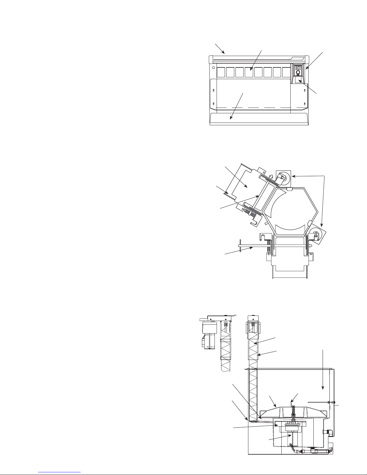
Service
2
Dispense chute cover removal
1. Remove top cover.
2. Push chute cover up vertically to slip off
holding tab.
3. After clearing tab, pull chute cover forward
to remove.
Auger motor assembly removal
1. Remove top cover.
2. Remove one thumbnut on rear of motor bracket.
3. Lift motor bracket and motor up, unplug electric
quick disconnects and remove.
Dispense mechanism assembly removal (Fig. 2)
1. Remove top cover.
2. Remove chute cover (see above).
3. Remove auger motor assembly (see above).
4. Remove quick release pins from the ice chutes
and gates, then unplug wires from solenoids.
5. Lift dispense mechanism up and off auger tube.
Fig. 1
Fig. 2
Front View – RH, 8-valve unit
top cover
valves
drain pan
assembly
Top View – Dispense assembly
(RH unit with bath shown)
gate
ice
chute
quick
release
pin
chute
cover
dispense
chute
solenoid
Auger and auger tube removal (Fig. 3)
1. Remove auger motor and dispense mechanism
assembly (see above).
2. Pull auger upward to clear auger tube.
3. Lift auger tube upward to clear dispenser top.
4. Slide tube and bearing plate through auger
tube gasket.
Dispense wheel removal
1. Remove drain pan assembly and bin access
cover.
2. Remove center thumbnut and threaded rod on
dispense wheel assembly and lift wheel out front
access opening.
Fig. 3
quick
release
pin
Side View
auger motor
baffle
plate
auger
bearing
plate
Front View – Dispenser
auger
stationery
auger
tube
dispense
wheel
agitator
rotating
agitator
13
wheel
motor
mounting
plate
wheel
motor
Page 14
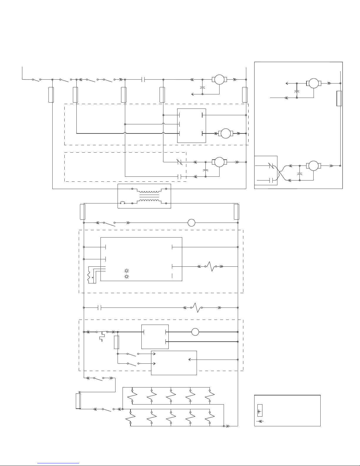
Wiring diagram
Right hand unit Left hand unit
L1
BLACK
POWER
SWITCH
BLACK
PL1-1
GRAY
NO
LID
C
DRAIN
SWITCH
C
TOP LID
SWITCH
POWER
BLACK
BEVERAGE COOLING OPTION
AUTOFILL OPTION
24 V RED
RED
PAN
BLACK
NO
GRAY
PL6-1
C
SWITCH
RED
DISPENSE
SWITCH
C
REAR
LID
PL1-2
NO
BROWN
NO
ORANGE
READY
ORANGE
PL6-3
DISPENSE
R1
4
ORANGE
115 VOLTS
T1
24 VOLTS
PURPLE
7
BROWN
PURPLE
MTR
PURPLE
AUTOFILL
PURPLE
AUTOFILL
COUNTERCLOCKWISE ROTATION
PL2-1
PL2-3
L2
MTR
WHITE
READY
LID
PUMP
BATH CONTROL
BOARD
COUNTERCLOCKWISE ROTATION
R2
PL3-2
RED
7
9
B
BLUE
R1
RED
PL3-1
BLUE
YELLOW
A
1
R2
6
DISPENSE RELAY
AUGER MOTOR
REDRED
M1
BLUEBLUE
WHITE
BATHPUMP MOTOR
PL5-1
M3
BLK
(35 MIN ON DELAY)
WHEEL MOTOR
RED
M2
BLUE
WHITE
YELLOW
BLK
BLK
PL2-2
PL5-2
PL3-3
L2
WHITE
WHT
24 V YEL
L2
AUTOFILL
PURPLE
ORANGE
1
6
PURPLE
R2
7
9
CLOCKWISE ROTATION
PL2-1
RED
PL2-3
BLUE
CLOCKWISE ROTATION
PL3-2
RED
RED
PL3-1
BLUE
BLUE
AUGER MOTOR
RED
M1
BLUE
WHEEL MOTOR
RED
M2
BLUE
BLK
BLK
PL2-2
PL3-3
L2
WHITE
L2
WHT
RED
RED
24VAC RED
BATH SOL
C
TEMP
SENSOR
T
BEVERAGE COOLING OPTION
DISPENSE
R1
RED
9
6
PL6-2
RED
RED
BIN T'STAT
PL6-4
3322
BLUE
T- S TAT
BLUE
BLUE
AUTOFILL OPTION
PL1-3
BEV HARN
BROWN
C
DRAINPAN
SWITCH
BROWN
PL7-1
KEYSWITCH
(OPTIONAL)
PL1-4
NO
BATH CONTROL BOARD
24VAC YEL
STATUS LIGHTS
GREEN - COLD
RED - WARM
BROWN
IM_#1
SWITCH
IM_#2
BLACK
Valve_1
BLACK
Valve_6
BATH SOL
AUTOFILL TIMER
18 MIN OFF
5 SEC ON
BLUE
BIN SIGNAL (24V)
ICEMAKER #1
RED
BIN SIGNAL (24V)
ICEMAKER #2
Valve_2
24V JUNCTION BOX
YELLOW
BATH
SOLENOID
PL4-2
PL4-3
BROWN
Valve_3
Valve_8Valve_7
BLUE
(12 SEC ON: 1 MIN OFF)
DISPENSE
SOLENOID
AUTOFILL RELAY
R2
B
Valve_4
Valve_9
BLACK
NO
NC
12
3
A
YELLOW
PL4-1
PL4-4
YELLOW
YELLOW
Valve_5
BLACK
Valve_10
YELLOW
YELLOW
PL7-2
YELLOW
LEGEND
TERMINAL STRIP CONNECTION
PIN and SOCKET CONNECTION
14
Page 15
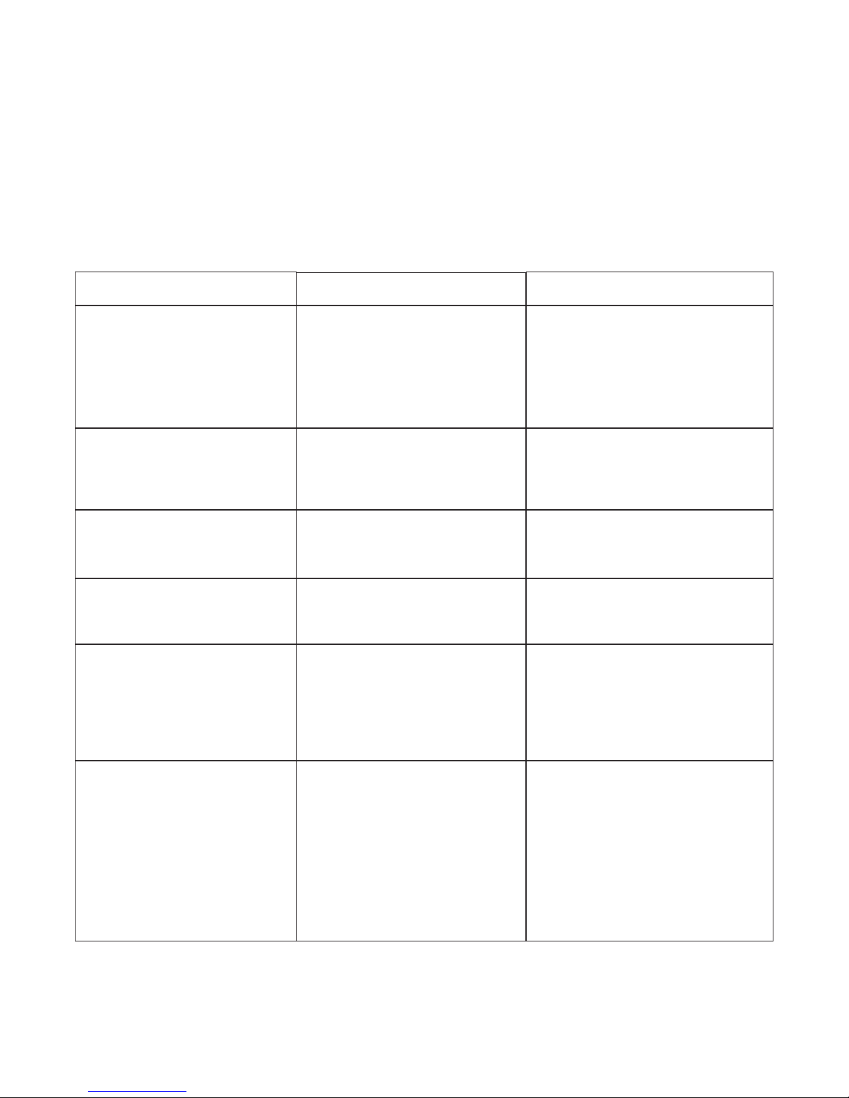
Dispenser troubleshooting guide
Before calling for service
1. Check that ice is in the dispenser and that congealed cubes are not causing a jam.
2. Check that circuit breaker and switches are in ON position.
3. Check that drain pan, rear lid and top are on securely. If ajar, dispenser will not operate. When the top is off,
auger does not operate, even though the solenoids do (page 16).
4. Check that all drains are clear.
Note: For units equipped with Follett compressed nugget icemaker, see Icemaker Operation and Service
Manual for service and troubleshooting information.
Symptom
Ice does not dispense.
• Auger motor does not run
• Wheel motor does not run
Ice does not dispense.
• Auger motor runs
• Wheel motor runs
• Gate does not open
Ice does not dispense.
• Auger motor does not run
• Wheel motor runs
Ice does not dispense.
• Auger motor runs
• Wheel motor does not run
Warm drinks or soda foaming.
No ice in dispenser.
Possible cause
1. Power switch faulty or in OFF
position; loose connection.
2. Faulty dispense switch.
3. Faulty transformer.
4. Drain pan ajar.
5. Faulty drain pan safety switch.
1. Loose electrical connection.
2. Linkage problem between
solenoid and gate.
3. Faulty solenoid.
1. Loose electrical connection.
2. Faulty auger motor.
3. Faulty run capacitor.
1. Loose electrical connection.
2. Faulty wheel motor.
3. Faulty run capacitor.
1. No ice in storage bin.
2. Water drained out of ice water
bath.
3. Circulating pump not running.
1. Power switch in OFF position
or faulty.
2. Bin signal switches in OFF
position or faulty.
3. Faulty bin thermostat.
4. Faulty transformer.
5. Icemaker related problem.
6. Faulty or disconnected wiring.
Solution
1. Turn power switch to ON position;
check connections.
2. Replace switch.
3. Replace transformer.
4. Check pan and reseat.
5. Replace switch.
1. Check connections.
2. Check linkage.
3. Replace solenoid.
1. Check connections.
2. Check auger motor.
3. Check run capacitor.
1. Check connections.
2. Check wheel motor.
3. Check capacitor.
1. Fill storage area with ice or check
icemaker operation.
2. Check that ice water bath drain
tube is in xed upright position.
3. Check pump and PC board for
output.
1. Check switch and replace, if
necessary.
2. Check switch and replace, if
necessary.
3. Replace bin thermostat.
4. Replace transformer.
5. Refer to icemaker Operation and
Service Manual for diagnosing.
6. Check for power and bin signal on
icemaker PC board.
If problems persist after following this basic troubleshooting guide, call Follett’s
technical service department at (800) 523-9361 or (610) 252-7301.
15
Page 16
Operational Status
I
0
I
0
I
0
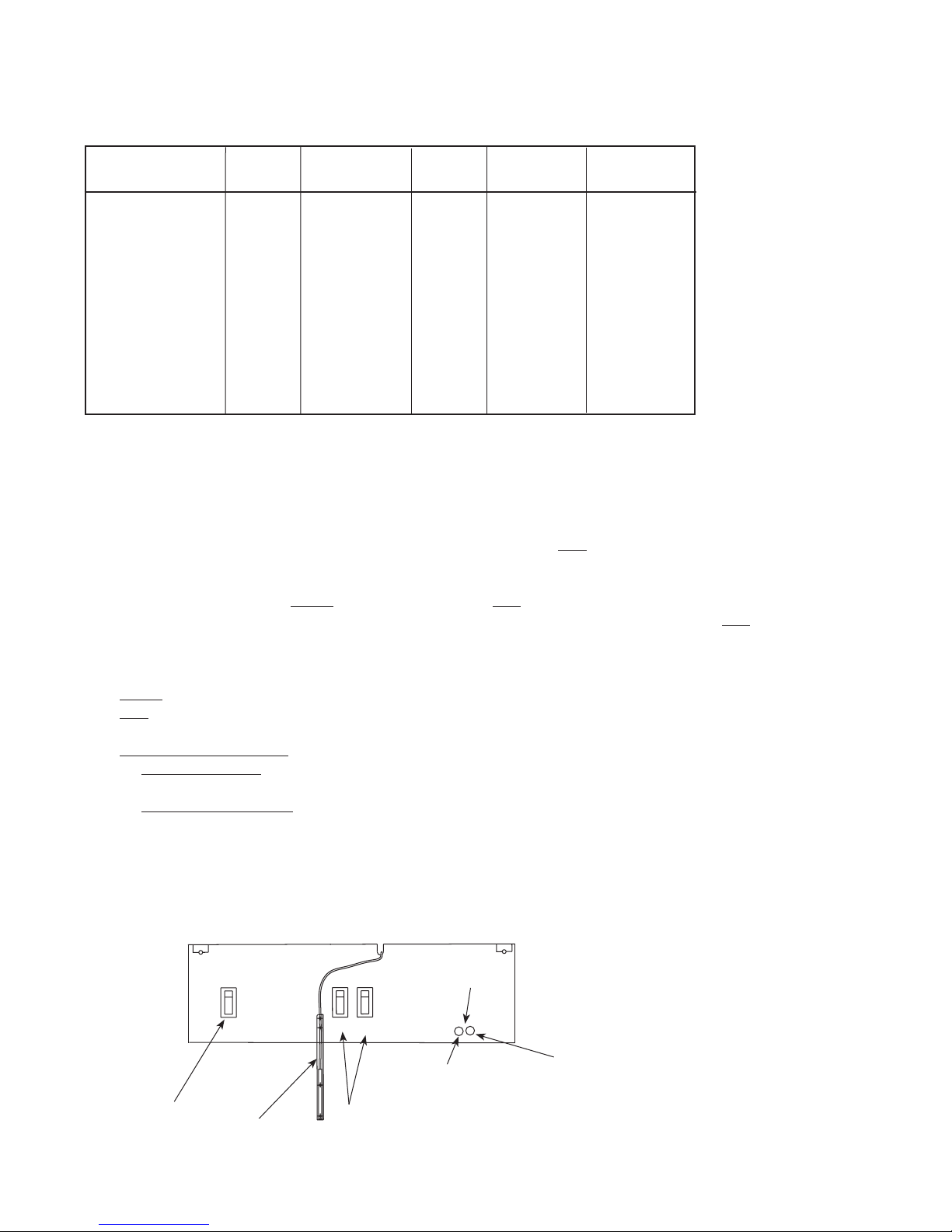
The chart below shows the operational status of various parts when certain switches are turned off or accessories
are removed.
Condition Pump Solenoids Auger Wheel Beverage
valves
Top lid off OFF ON OFF OFF ON
Rear lid off ON ON OFF OFF ON
Drain pan off ON ON OFF OFF OFF
On/off switch
in off position OFF OFF OFF OFF OFF
Beverage switch
in OFF position ON ON ON ON OFF
Waterbath circuit board operation
The temperature sensor is hard wired directly to the circuit board. The waterbath circuit board operates on
24 volts AC. The bath pump will run for 35 minutes whenever ice is dispensed or the bath calls for ice.
Optimal beverage temperature is controlled by the circuit board located in the electrical box. The board monitors
the waterbath temperature and holds it to a factory setting. When the Red LED is ON, the bath solenoid, auger
motor, wheel motor and bath pump are energized. Ice will be dispensed into the waterbath for 12 seconds, then
stop for 60 seconds. The pump will stay energized, and the circuit board will then monitor the water temperature.
If it is below the set point, the Green LED will come on, the Red LED light will go off, and ice will not dispense
into the waterbath. If the temperature of the bath is determined to be above the set point, the Red LED will
remain on. The circuit board has a delay of 60 seconds before more ice is dispensed into the waterbath.
LED indicators:
Green – the waterbath is at the set temperature.
Red – the bath temperature is above the set temperature and the bath is calling for ice.
Flashing LED indicators:
Flashing Red and Green – the circuit board has gone into an error mode:
Alternate ashing – circuit board has power and is waiting for hopper cover and dispenser top to be
replaced.
Simultaneous ashing – the waterbath did not reach set temperature in 40 minutes. Reset this error
mode by turning power off, removing top lid, drain pan or rear lid.
Front View – Electrical box
bev. bath
indicator
power on/off
switch
probe
#1 #2
cold/green LED
warm/red LED
icemaker
switches
16
Page 17
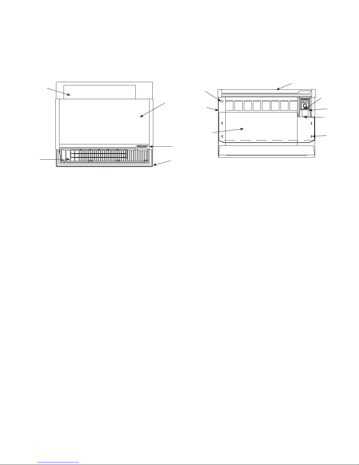
Replacement parts
Dispenser exterior
Order parts online
www.follettice.com
Top View
8 valve (8v) unit with right hand (RH) tower
8
1
2
7
Reference # Description Part #
1 Lid, 8 valve unit (includes “Follett” label) 502436
1 Lid, 10 valve unit (includes “Follett” label) 502437
2 Label, “Follett” 502438
3 Cover, dispense chute, lever operation 502439
3 Cover, dispense chute, push-button operation (includes button) 502440
4 Switch, push-button operation 502441
5 Backsplash, RH unit, 8 valves 502445
Not shown Backsplash, LH unit, 8 valves 502444
Not shown Backsplash, RH unit, 10 valves 502443
Not shown Backsplash, LH unit, 10 valves 502442
6 Drain pan, 8 valve unit 502446
Not shown Drain pan, 10 valve unit 502447
7 Grille, drain pan, 8 valve unit 502450
Not shown Grille, drain pan, 10 valve unit 502451
8 Cover, ice storage bin, rear — all U155 units (except N units) 502452
Not shown Cover, ice storage (under drain pan) — all U155 units 502453
9 Switch, key lock for valves 501409
Not shown Key, beverage lock switch 501286
10 Panel, end, beverage, RH unit 502584
Not shown Panel, end, beverage, LH unit 502583
Not shown Panel, access, RH and LH units 502585
Not shown Panel, rear, motor support, RH unit 502586
Not shown Panel, rear, motor support, LH unit 502587
Not shown Panel, front, dispense mechanism, RH unit 502588
Not shown Panel, front, dispense mechanism, LH unit 502589
Not shown Panel, rear, 8v 502590
Not shown Panel, rear, 10v 502591
11 Label, ice, dispense cover, push-button 502623
Not shown Label, ice, dispense cover, lever 502622
Not shown Clip, Tinnerman, 10-32 502621
12 Thumbscrew, backsplash, 10-32 x 1/2 501100
Not shown Legs, 6" (153mm) adjustable to 9" (229mm) — set of 4 502454
Not shown Screw, 10-32 x 1/2 502287
Not shown Plug 2 lead, male 502333
Not shown Plug 2 lead, female 502334
6
8 valve (8v) unit with right hand (RH) tower
9
10
5
Front View
(push-button dispensing)
1
4
11
3
12
17
Page 18
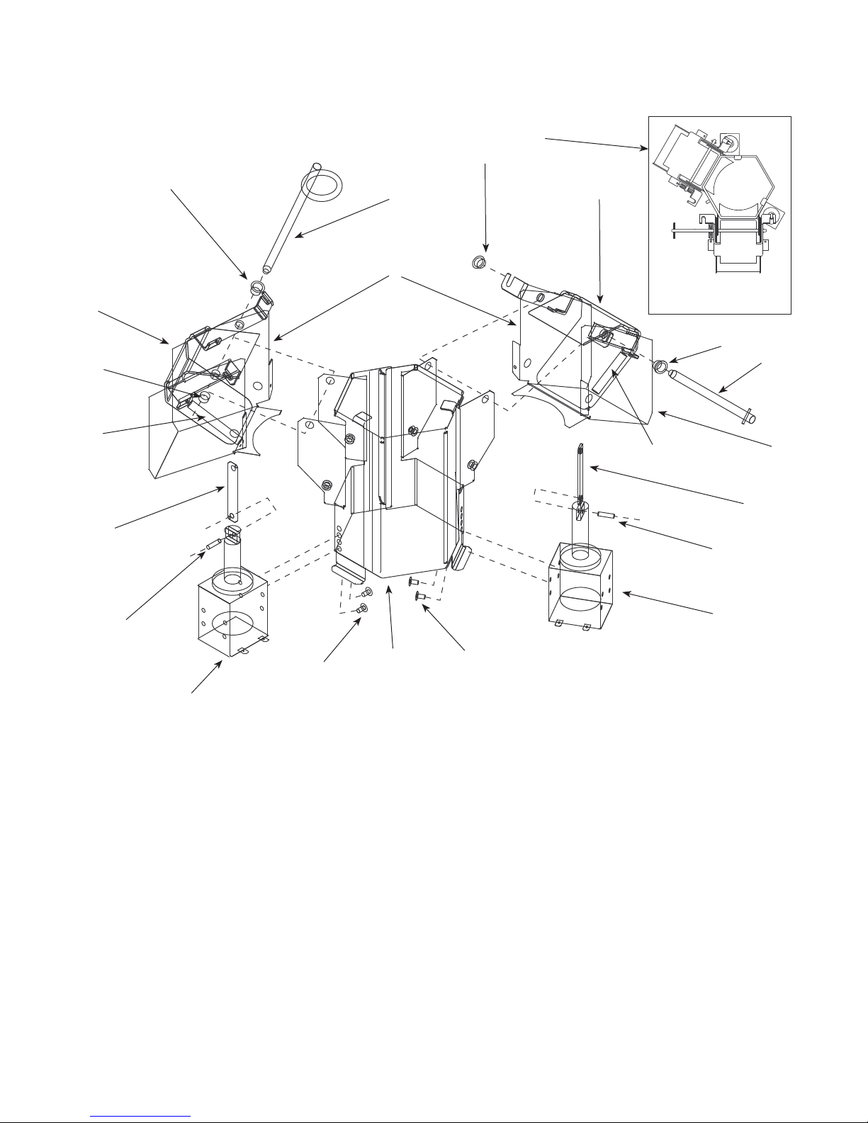
Dispense assembly
Dispense assembly, Side View
(RH unit with bath shown)
Order parts online
www.follettice.com
6
10
1
10
10
4
8
7
2
1
Top View
10
3
7
12
8
2
12
11
9
5
Reference # Description Part #
1 Gate, dispense 502455
2 Linkage pin, gate/solenoid 502456
3 Pin, quick release, 3" (77mm), bath gate and lever 501949
4 Pin, quick release, 5.53" (141mm), dispense gate 502102
5 Solenoid (includes linkage pin) 00126607
6 Dispense mechanism assembly, bath, RH unit 502448
Not shown Dispense mechanism assembly, bath, LH unit 502449
Not shown Dispense mechanism assembly, non-bath RH unit 502458
Not shown Dispense mechanism assembly, non-bath, LH unit 502496
7 Spring, dispense mechanism (1 per side) 501950
8 Chute, ice 502457
9 Wrap, dispense mechanism 502607
10 Bushing, Ni liners 501249
11 Screw, 8-32 x 5/16 502625
12 Pin, spring 502624
Not shown Push pins, clear chute 502618
Not shown Chute, focus — clear plastic 502459
Not shown Lever, dispense 501953
11
5
18
Page 19
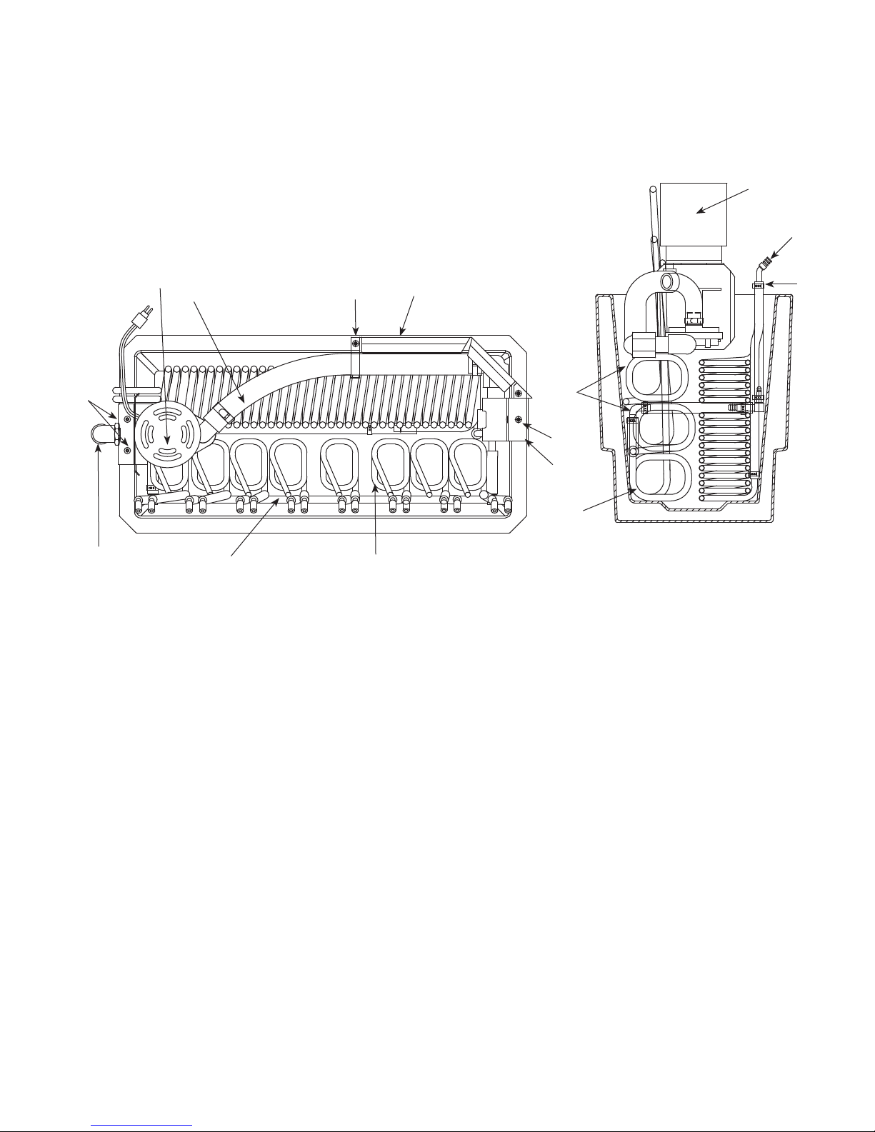
Waterbath
Order parts online
www.follettice.com
Side View
4
Top View
4
5
10
6
Reference # Description Part #
1 Coil, 14" (356mm) riser — carbonated water 00107391
2 Coil, 12-1/2" (318mm) riser — plain water/carbonated water 502461
3 Coil, syrup 502462
4 Pump, water bath (includes mounting plate and elbow) 00111476
5 Pump, discharge assembly, RH, 8v (includes 2 elbows) 00109314
Not shown Pump, discharge assembly, LH, 8v (includes 2 elbows) 00109322
Not shown Pump, discharge assembly, RH, 10v (includes 2 elbows) 00109330
Not shown Pump, discharge assembly, LH, 10v (includes 2 elbows) 00109348
6 Elbow, over ow drain, 1" (26mm) x 3/4 MPT 502465
Not shown Elbow, clean-out drain, 3/8" (10mm) x 3/8 MPT 502466
7 Manifold, carbonated water, 8 valve unit 502468
Not shown Manifold, carbonated water, 10 valve unit 502469
Not shown Manifold, 8 valve unit without beverage bath 502470
Not shown Manifold, 10 valve unit without beverage bath 502494
8 Bath, splash shield, RH 502596
Not shown Bath, splash shield, LH 502595
9 Clamp, elbow, bath 502626
10 Screw, 8 x 1/2, stainless 502627
11 Fitting, beverage valve 207855
12 Clamp, Otieker, 1/4" (7mm) 00113761
10
8
2
10
9
1
37
11
12
19
Page 20
2
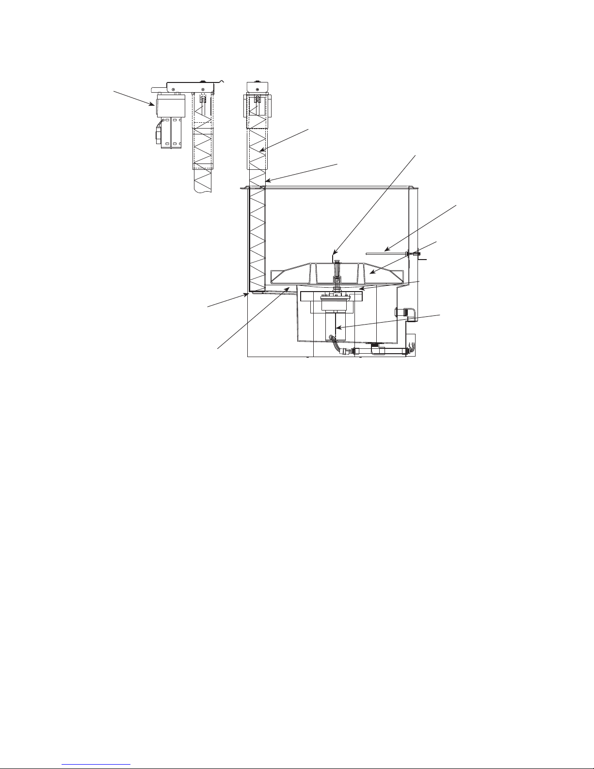
Hopper
Order parts online
www.follettice.com
5
1
7
2
Side View
9
3
8
10
6
4
Reference # Description Part #
1 Auger, LH unit (black, stamped with “1”) 502491
Not shown Auger, RH unit (gray, stamped with “2”) 502492
2 Tube, auger, LH unit with beverage bath 502486
Not shown Tube, auger, RH unit with beverage bath 502485
Not shown Tube, auger, RH unit without beverage bath 502487
Not shown Tube, auger, LH unit without beverage bath 502488
3 Wheel, dispense (includes stud and rotating agitator) 501681
4 Baffle (under dispense wheel) 501684
Not shown Drive bar (under dispense wheel) 501682
5 Motor, vertical auger 502476
6 Motor, wheel 502560
Not shown Seal, wheel motor 501333
Not shown Spacer, wheel motor 501768
Not shown Capacitor, wheel motor 501782
7 Agitator, rotating, 21" (534mm) long 502484
8 Plate, wheel motor mounting 502615
9 Agitator, stationery 502490
10 Plate, auger bearing 501696
Not shown Bracket, ice tube, double tube 502497
Not shown Ice transport tube (sold by the foot) 500366
Not shown Ice transport tube, 10 ft 502522
Not shown Ice transport tube, 20 ft 502523
Not shown Insulation, transport tube (sold by the foot) 501176
Not shown Cover, blank ice entry 502674
Not shown Thermostat 501432
Not shown Gasket, ice entry 502672
Not shown Plate, ice entry, 2 holes 502673
20
Page 21
Auger motor
Order parts online
www.follettice.com
7
6
3
4
6
9
1
8
Side View
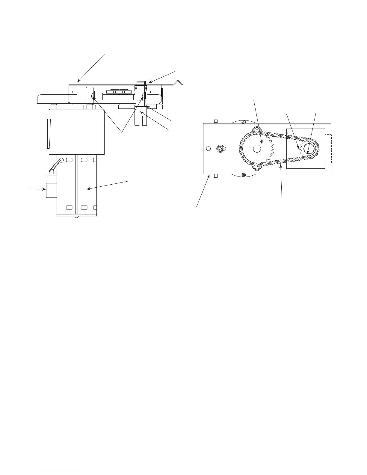
Reference # Description Part #
Auger motor/drive assembly, vertical (includes all items below) 502493
1 Motor, vertical auger (includes gearbox and capacitor) 502476
2 Chain, auger drive #35, 40p 502477
3 Sprocket 35#, 22T 5/8 bore 502478
4 Sprocket 35#, 12T 5/8 bore 502479
5 Drive shaft 502480
6 Bearing, auger, upper and lower 501314
7 Cover and bearing, chain drive (includes 501314) 502481
8 Capacitor, 25mf, 270V 501550
9 Key, Woodruff 502482
10 Washers, thrust, (4) 501765
11 Mounting plate, auger motor (includes 501314) 502483
5
2
11
Top View
10
21
Page 22
Electrical components
Order parts online
www.follettice.com
Side View
OM
C
O.
.
N
Top View
1
5
2
9
Front View
4
III
000
#1
#2
5
circuit board
BEV. BATH INDICATOR
COLDWARM
3
7
LID
PUMP
L2 (WHT)
BEVERAGE BATH CONTROL BOARD DETAIL
ready
(orange)
NO
NC
C
MTR
24VAC (RED)
24VAC (YEL)
6
6
8
7
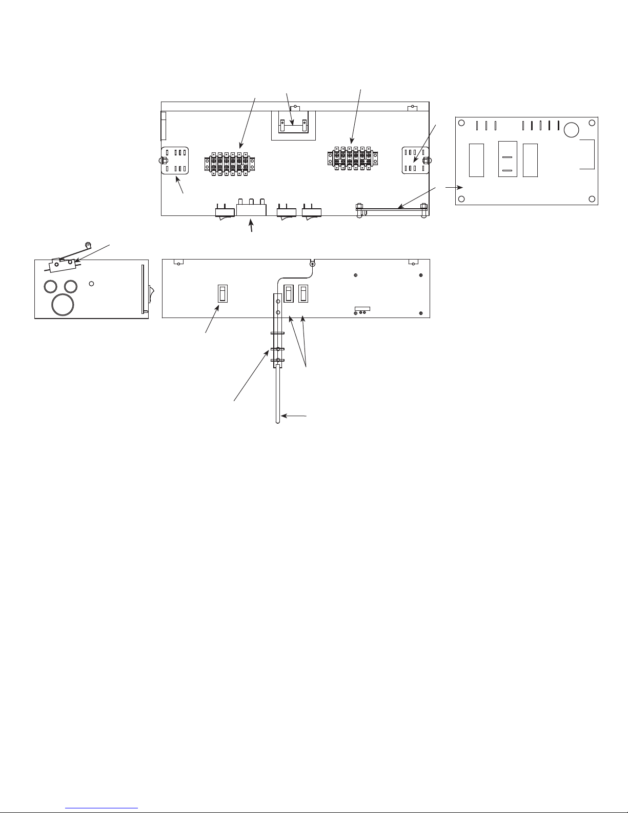
Reference # Description Part #
1 Transformer, 24V 502058
2 Relay, auto ll 501826
3 Relay, dispense 501826
4 Timer, auto ll (automatic ll units) 502471
5 Strips, terminal 502472
6 Switches (power and icemaker) 502209
7 Board, circuit and probe (one unit) 502473
8 Bracket, probe 502474
9 Switch, safety 502511
Not shown Switch, safety, rear cover assembly, LH unit 502498
Not shown Switch, safety, rear cover assembly, RH unit 502499
Not shown Switch, safety, drain pan assembly, LH unit 502500
Not shown Switch, safety, drain pan assembly, RH unit 502501
Not shown Switch, dispense, lever 502505
Not shown Bracket, safety switch, rear 502608
Not shown Bracket, safety switch, drain pan, RH 502609
Not shown Bracket, safety switch, drain pan, LH 502610
Not shown Thermostat, bin level 500514
22
Page 23

This page intentionally left blank.
23
Page 24

801 Church Lane • Easton, PA 18044, USA
Toll free (800) 523-9361 • (610) 252-7301
Fax (610) 250-0696 • www.follettice.com
208598R05
06/09
 Loading...