

Page 1
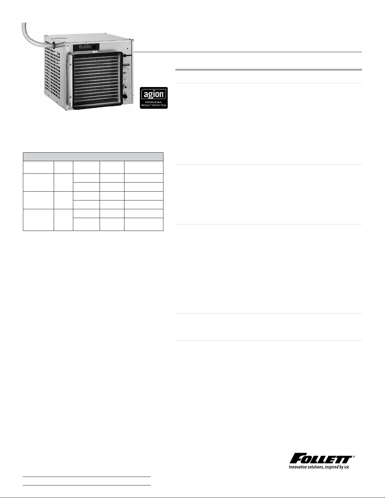
MCD425ABS shown
Maestro Plus 425 series ice machine, 115V/60 Hz
Install/
1
For use with
ice storage
bin
Follett
Vision™
dispenser
ice and
beverage
dispenser
(by others)
† ENERGY STAR® certified
1
Ordered separately
mount Condenser V/Hz/Ph Item number
RIDE
RIDE
RIDE
air
water
air
water
air
water
115/60/1
115/60/1
115/60/1
115/60/1
115/60/1
115/60/1
MCD425ABS†
MCD425WBS
MCD425AVS†
MCD425WVS
MCD425AHS†
MCD425WHS
™
Maestro Plus
self-contained 425 series Chewblet® RIDE® ice machine
Features
Maestro Plus Chewblet ice machine with up to 425lb(193.0 kg)
dailyproduction of consumer-preferred Chewblet ice
- automatically transport ice through a tube with RIDE
technology from up to 20' (6 m) away
- available with approximately 1.00" (2.54 cm) long standard
Chewblet ice
- environmentally responsible R404a refrigerant has zero
ozonedepletion potential
- water and energy ecient
- no noisy harvest cycles means quiet ice production
Consumer-preferred Chewblet ice
- preferred over cubes by more than 2:1
- easy to chew
- more reliable dispensing than nugget or pellet ice
- slow melting, maintains drink temperature and quality
comparable to cubes
- higher displacement than cube ice
Key Maestro Plus design features
- durable construction, versatile design – sturdy stainless steel
exterior frame
- stainless steel evaporator, auger and top bearing
- oversized, heavy duty, tapered roller bearings ensure long, lowmaintenance life
- automatic self-flushing of ice machine removesimpurities
- compact design oers in-cabinet/undercounter, floorstand,
wall bracket, on-fountain dispenser, or on-bin mounting
- 10 ft (3 m) flexible ice transport tube and insulation standard
with RIDE model ice machines (except for “V” models)
Maintenance and service benefits
- cleaning and sanitizing of entire machine takes less than1 hour
- LED control board provides at-a-glance machine status
Warranty
- 3 years parts and labor, 5 years compressor parts
1 Consumer study conducted by independent agency Roper ASW.
1
Job
Item
801 Church Lane | Easton, PA 18040, USA
1.800.523.9361 | 1.610.252.7301 | follettice.com
Page 2
Accessories
Water filters (refer to form# 6380, 9905, 6070)
Nu-Calgon IMS-III sanitizer, 16 oz bottle (item# 00979674)
SafeCLEAN™ environmentally responsible ice machine cleaner
(item#00132001)
Wall mount bracket (see accessory form# 3311)
Slide-out track accessory – allows RIDE model ice machines to slide-
out without disconnecting utilities (seeform#3311)
Ice machine stand, height-adjustable (seeform#3311)
Longer ice transport tube (10'/3 m is standard) – Specify length:
____ft/m in 5'/1.5 m increments (20' max)
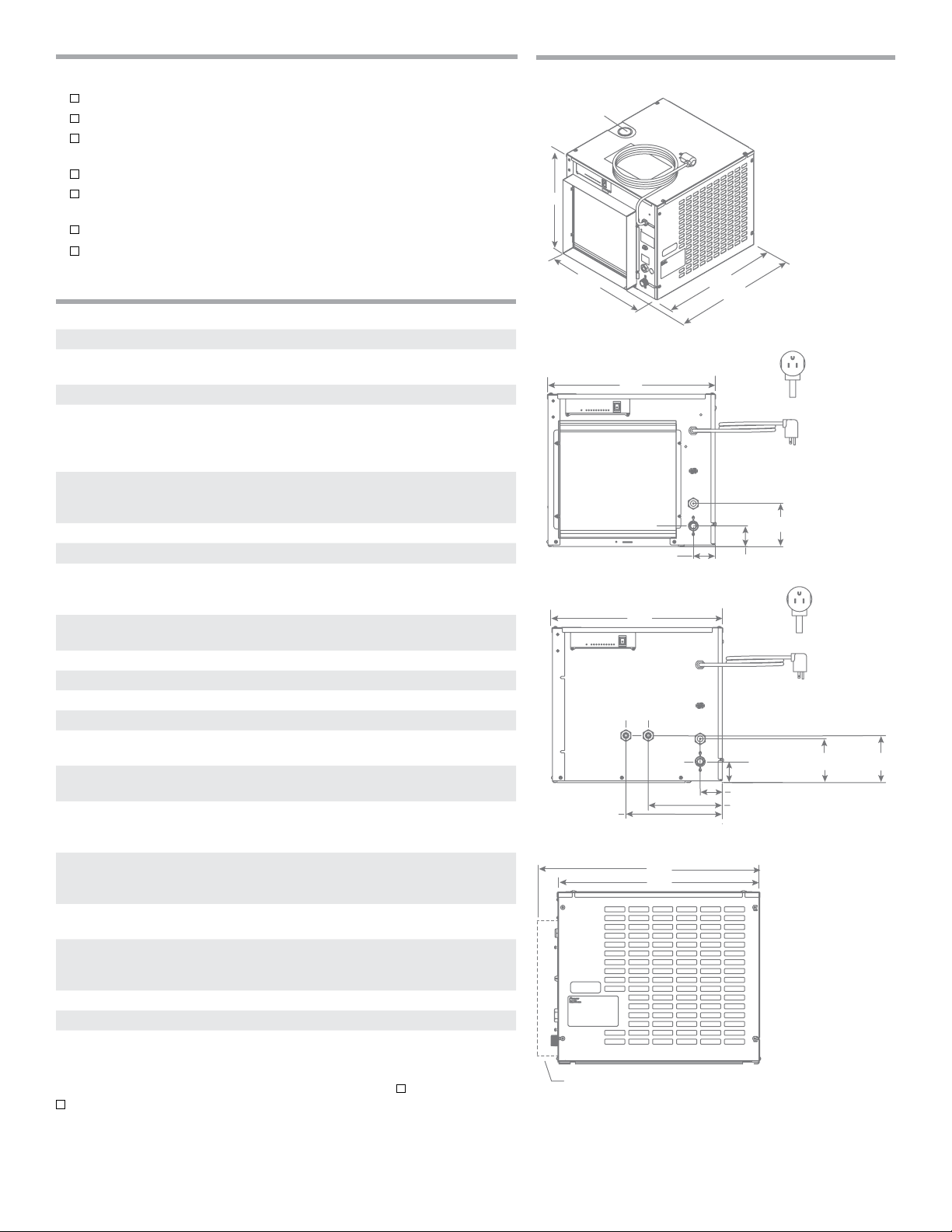
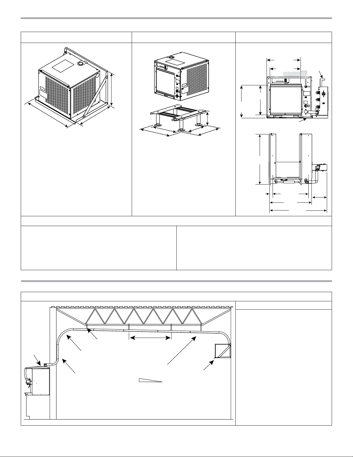
Specification
W1 Width 18.80" (47.8 cm)
Depth D1 air-cooled – 22.09" (56.1 cm)
D2 water-cooled – 20.00" (50.8 cm)
H1 Height 17.10" (43.4 cm)
Service clearance 12.00" (30.5 cm) top –
nofrontobstructions
6.00" (15.24 cm) on exhaust side
(left, right and rear)
C1 Electrical
115 V/60/1 – MCD425 models
C2 Ice transport tube see page 7 for details
C3 Water inlet 3/8" FPT
C4 Drain 3/4" MPT
Water-cooled ice machine
connections
Air temperature 50 - 100 F (10 - 38 C)
Water temperature 45 - 90 F (10 - 32 C)
Potable water pressure 10 - 70 psi (69 - 483 kPa)
Condenser water pressure 10 - 125 psi (69 - 861 kPa)
Ice production at 70 F (21 C) air,
50 F (10 C) water
Ice production at 90 F (32 C) air,
70 F (21 C) water
Energy consumption
90 F (32 C) air,
70 F (21C) water
Heat rejection air-cooled models – 5,000 BTU/hr
Water consumption 12.0 gal (45.4 L) of potable water
Water flow requirement for
water-cooled models
Approximate ship weight 160 lb (73 kg)
NOTE: For indoor use only
SHORT FORM SPECIFICATION:
________________ [condenser type, from model number guide] capable of producing
compressed nugget ice using an ecient, sanitary vertical evaporator/auger system
and delivering ice by a flexible wire reinforced, transport tube to ice storage bin, or
ice and beverage dispenser and provided with a stainless steel frame, plus all the
features listed and mounting/performance-enhancing accessories checked above. Ice
machine to be equipped with automatic self-flushing.
11 amps, 0.8 kW, requires dedicated
15 amp circuit,
7' (2 m) cord, NEMA 5-15 plug
water-cooled models require
separate condenser drains
C5 – 3/8" FPT condenser inlet
C6 – 3/8" FPT condenser drain
air-cooled models – 425 lb (193.0 kg)
water-cooled models – 443 lb (201.1 kg)
air-cooled models – 325 lb (147.6 kg)
water-cooled models – 372 lb (169.0 kg)
air-cooled models – 5.4 kWh
water-cooled models – 5.0 kWh
per 100lb(45.4 kg) ice
water-cooled models – 1,400 BTU/ hr
to air, 3,600 BTU/hr to water
per 100lb (45.4 kg) of ice
0.25 gpm at 50 F (10 C)
0.5 gpm at 70 F (21 C)
1.25 gpm at 90 F (32 C)
Ice machine to be a Follett® model number
Dimensional drawing
C2
H1
W1
Front view — air-cooled, RIDE models
W1
C4
2.50" (6.35 cm)
Front view — water-cooled models
W1
C5
C6
)
Side view — air-cooled and water-cooled models
D1
D2
air-cooled RIDE models only
D2
C3
C3
C4
D1
C1
4.75" (12.07 cm)
2.25" (5.71 cm)
(12.07 cm)
2.25"
(7.72 cm)
2.50" (6.35 cm)
8.25" (20.96 cm)
C1
4.75"
5.25"
(13.35 cm)
2
Form# 6695
Self-contained 425 series RIDE ice machine
Page 3
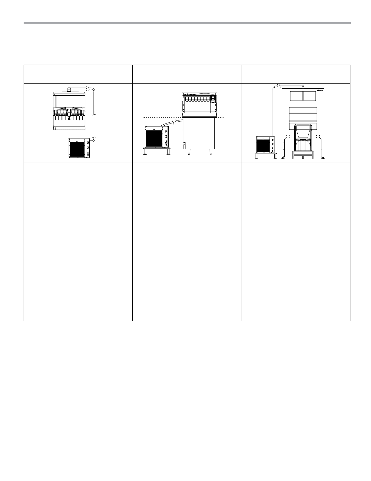
1 – Locating the ice machine
Maestro Plus self-contained Chewblet ice machines with RIDE technology allow mounting in a base cabinet, on a wall or
on a floor stand up to 20' (6 m) from the dispenser or ice bin. In-cabinet mounting requires special attention to service
access, unit ventilation and ice tube runs.
RIDE model – ice and beverage
dispensers (by others)
Important specifier notes: Important specifier notes: Important specifier notes:
1. Dispenser must be compatible with
nugget ice. Compatible dispensers
include Cornelius DF/ED300BC,
DB/DF/ED, 150BC, 175 BC, 200BC,
250BC, 300 BC, IDC215/255,
FlavorFusion/Overload, Lancer
4500-22N, 4500-30N, FS16N, FS30N,
FS44N, Servend MD150/175/200/250,
MDH302/402, SV175/200/250 and
Coca-Cola Freestyle.
2. Ice enters through the top of the ice
and beverage dispenser. Contact factory
for side entry.
3. Top kit MSF30SC required with CocaCola Freestyle 7000. Adapter 0002832
must also be ordered from Coca-Cola.
4. RIDE application is approved only for
Pepsi Spire 3.0 and 5.0 designed for
top mount ice machines and requires
MSP24SC for 3.0 and MSP30SC for
5.0, ordered separately. For manual
fill versions of PepsiSpire 3.0 and 5.0,
contact factory.
RIDE model – Follett low-profile
Vision ice and beverage dispensers
1. See pages 4-6 for critical clearance and
venting requirements.
RIDE model – Follett ice storage bins
1. See form# B300 for bin sizing.
2. Locate floor sink or grate and drains in
front of storage bin.
3. Do not position bin drain lines to block
Ice•DevIce
™
bin cart.
Self-contained 425 series RIDE ice machine
Form# 6695
3
Page 4

2 – Undercounter/in-cabinet mounting
Cabinet details
Important specifier notes
1. Cabinet door opening
must meet minimum size
requirements shown and be
free of obstructions to allow
ice machine to slide out
(no lip or utilities to block
removal).
2. Cabinet base must be
capable of supporting ice
machine and allow ice
machine to rest flat on
cabinet bottom.
3. No counter supports, electric
or plumbing can run in front
of the ice machine.
cabinet door opening
19.00"W x 17.50"H (48.3 cm x 44.5 cm) minimum,
24.75"W (62.9 cm) minimum for centered air intake grille
slides
out
cabinet base
must be flat and free of obstructions
(no lip or utilities to block removal)
4
Form# 6695
Self-contained 425 series RIDE ice machine
Page 5

3 – Undercounter/in-cabinet mounting and ventilation
Using Follett supplied grilles
Maestro Plus ice machines can be installed undercounter/in-cabinet to fill bins or dispensers using RIDE technology. Care must be
taken to ensure proper cabinet venting to avoid recirculation of hot air. Improper venting can cause ice machine outages.
Supplied
grilles
18.00" (45.7 cm)
minimum
29.00"
(73.7 cm)
minimum
Maestro Plus
ice machine
22.75" (57.8 cm)
minimum
electric
Ice transport tube
minimum 1/4" per foot
(2 cm per meter)
pitch toward ice machine
secure to prevent dips
and traps from forming
exhaust
cabinet door
supplied air
intake grille
air in
air intake gasket
door & gasket
must mate
directly
cutout for supplied air intake grille
12.00"W x 12.00"H (30.5 cm x 30.5 cm)
Cabinet door
must mate directly
to air intake gasket
drain
water
completed installation with
gasket and door in place
side view
22.75" (57.8 cm)
drain tube
A
29.00"
(73.7 cm)
minimum
Important specifier notes for using Follett supplied grilles:
1. The supplied exhaust grille must be located at least
18.00"(45.7cm) from the supplied air intake grille (exhaust air
must notrecirculate with intake air).
2. Cabinet interior must be open to allow for unrestricted
exhaust airflow.
3. Ice transport tube needs minimum 1/4" per foot
(2 cm per meter) pitch toward ice machine and should be
secured to prevent dips and traps from forming.
Self-contained 425 series RIDE ice machine
A: additional 3" (7.6 cm) required if
receptacle located directly behind unit.
4. Cabinet door must mate directly to air intake gasket.
5. Cabinet interior must provide a minimum clear space of
22.75" deep (57.8 cm) by 29.00" high (73.7 cm).
6. Supplied grilles must meet minimum requirements for open air
space shown above.
7. Utilities should be conveniently located as shown.
Form# 6695
5
Page 6
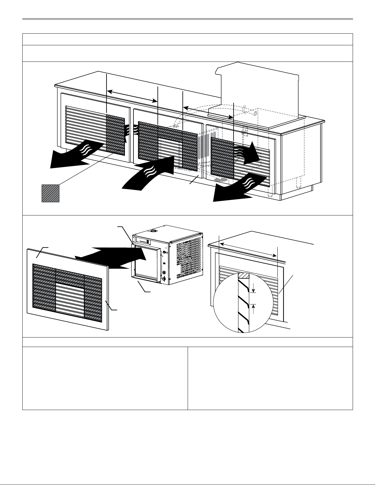
3 – Undercounter/in-cabinet mounting and ventilation (continued)
grilles by others/
minimum open air space
Using grilles by others/alternate cabinet ventilation
Cabinets with ventilation or louvers other than those provided by Follett require special consideration to provide proper ventilation.
Recirculation of hot air will reduce ice machine performance and can cause ice machine outages.
alternate cabinet
ventilation
18.00" (45.7 cm)
minimum
18.00" (45.7 cm)
minimum
exhaust
All counter ventilation
within 18.00" (45.7 cm) of
air inlet must be blocked to
prevent exhaust-air recirculation
air intake gasket
cabinet door
door & gasket
air in
cabinet door
must mate directly
to air intake gasket
exhaust
x
must mate
directly
Maestro Plus ice machine
grilles by others/
alternate cabinet ventilation
side
view
Important specifier notes for using grilles supplied by others/alternate cabinet ventilation:
1. Exhaust must be at least 18.00" (45.7cm) from air intake
(exhaust must notrecirculate with intake air).
2. Cabinet interior must be open to allow for unrestricted
exhaust air flow.
3. Ice transport tube needs minimum 1/4" per foot
(2 cm per meter) pitch toward ice machine and should be
secured to prevent dips and traps from forming.
4. Ducting must be provided if cabinet door does not mate
directly to air intake gasket.
5. Cabinet interior must provide a minimum clear space of
22.75" deep (57.8 cm) by 29.00" high (73.7 cm).
6. Grilles by others must meet minimum requirements for open
air space shown above.
7. Utilities should be conveniently located as shown.
xx
x
yn
= sq. in. of open air space
= (# of openings)
n
minimum 100 sq. in.
y
open air space
6
Form# 6695
Self-contained 425 series RIDE ice machine
Page 7
4 – Maestro Plus ice machine mounting accessories
bever
dispenser
(35.6 cm
Optional wall mount bracket Optional machine stand Optional slide out accessory
front view
14.00"
(35.6 cm)
13.00"
(33.1 cm)
18.125"
26.25"
(66.7 cm)
20.125"
(51.1 cm)
(46.0 cm)
6.80"
(17.27 cm)
A
B
C
D
12.75"
(32.4 cm)
14.00"
)
slide-out-track
top view
verical utility panel
A - 15.125" (38.4 cm)
B - 18.625" (47.3 cm)
C - 13.25" (33.6 cm)
D - 20.75" (52.7 cm)
Important specifier notes:
1. For secure wall mounting, specify optional wall mount bracket.
2. Wall and fasteners must support the weight of the ice
machine, bracket, supply water and ice. Use of a backing board
may be required with hollow wall construction.
3. Machine stand mounting adds 6.80" (17.27 cm) to height of
ice machine.
4. No dips in tube routing allowed.
5. Ice transport tube needs minimum 1/4" per foot (2 cm per
meter) pitch toward ice machine and should be secured to
prevent dips and traps from forming.
5 – Maestro Plus ice tube runs – specifier guidelines
Long tube runs for RIDE remote ice delivery equipment
age
support
straps
minimum of
6.00." (15.24 cm)
turn/corner
radius
ice transport tube –
1 3/16" OD,
2 1/8" OD with
insulation
maximum
2 ft (61.0 cm)
transport tube slope
(toward ice machine)
1/4"
1'
(2 cm per meter)
wall-mounted
ice machine
22.75"
(57.8 cm)
1.563"
(4.0 cm)
Icemaker Front
16.00"
(40.7 cm)
19.25"
(48.9 cm)
25.875"
(65.8 cm)
1.563"
(4.0 cm)
Important specifier notes:
1. 20' (6 m) maximum ice transport
tube run.
2. Tubing routing bends must have a
6.00" (15.24 cm) radius or larger.
3. If not supported from underneath,
secure insulated ice transport tube
at least every2' (61.0 cm) to prevent
dipsor traps.
4. Relative humidity levels above 80%
in areas where the ice machine or
ice transport tube are located may
produce excessive condensation that
will cause water damage.
5. Contact factory for
recommendations on running
tubing through a decorative soffit
orchase.
Self-contained 425 series RIDE ice machine
Form# 6695
7
Page 8

Ice production – air-cooled
Inlet water
temperature
F (C)
50 (10) 460 (208) 425 (193) 390 (177) 355 (161) 320 (145)
60 (16) 438 (198) 405 (184) 373 (169) 340 (154) 307.5 (139)
70 (21) 415 (188) 385 (190) 355 (173) 325 (147) 295 (134)
80 (27) 405 (184) 375 (170) 345 (156) 315 (142) 285 (129)
90 (32) 395 (179) 365 (166) 335 (152) 305 (138) 275 (125)
60 (16) 70 (21) 80 (27) 90 (32) 100 (38)
Ambient air temperature F (C)
Ice production – water-cooled
Inlet water
temperature
F (C)
50 (10) 486 (220) 465 (211) 443 (201) 422 (191) 400 (181) 389 (176)
60 (16) 464 (210) 445 (202) 425 (193) 406 (184) 386 (175) 367 (166)
70 (21) 443 (201) 425 (193) 408 (185) 390 (177) 372 (169) 358 (162)
80 (27) 422 (191) 406 (184) 389 (176) 373 (169) 356 (161) 340 (154)
90 (32) 400 (181) 385 (175) 371 (168) 356 (161) 341 (155) 326 (148)
50 (10)
60 (16) 70 (21) 80 (27) 90 (32) 100 (38)
Condenser water temperature F (C)
lb/kg production in 24 hr
lb/kg production in 24 hr
ENERGY STAR and the ENERGY STAR mark are registered trademarks owned by the U.S. Environmental Protection Agency.
Harmony, Ice•DevIce, Maestro Plus and Vision are trademarks of Follett LLC.
Chewblet, Follett and RIDE are registered trademarks of Follett LLC, registered in the US.
Follett reserves the right to change specifications at any time without obligation. Certifications may vary depending on country of origin.
Self-contained 425 series RIDE ice machine
Form #6695 08/16
© Follett LLC
801 Church Lane | Easton, PA 18040, USA
1.800.523.9361 | 1.610.252.7301 | follettice.com
 Loading...