

Follett Maestro Plus P425, Maestro Plus CP425W, Maestro Plus EP425W, Maestro Plus CP425A, Maestro Plus EP425A Installation Instructions Manual
Page 1

Installing Maestro Plus™ P425, EP425A/W or CP425A/W
Ice Machine Module into Symphony™
FB, CT, and CI Dispensers
Installation Instructions
Technical Support
If you experience any problems during the installation, please call Follett Technical Service toll-free at
(877) 612-5086 for assistance.
Description
Follow these instructions to install the Maestro Plus ice machine module into your Symphony FB, CT, and CI
dispenser.
CAUTION!
Only qualied technicians should attempt to service or maintain this equipment.
Parts
Common
(1) 1/4" X 1/4"PUSH IN VALVE 01035526
(1) CLAMP, ICE TRANSPORT TUBE 202011
(2) SANI-SPONGE 00131524
(2.5') 1/4" TUBING 205835
POWER CORD (1) 01075589
BIN SIGNAL RELAY ASSEMBLY
(1) 01069772
801 Church Lane • Easton, PA 18040, USA
Toll free (877) 612-5086 • +1 (610) 252-7301
www.follettice.com
Order parts online:
www.follettice.com
01033687R04
Page 2

FB Dispensers
(1) GUIDE PLATE RIGHT
01015759
(1) GUIDE PLATE LEFT 25/50
01015767
(1) GUIDE PLATE LEFT 110
01042654
SCREW
204139
CT Dispensers
(1) TOP MOUNT SPACER
01048578
(2) DRAIN ELBOW BARB FITTING
205624
(4) SCREW
208568
2 Maestro Plus P425/CP425/EP425 Ice Machine for Symphony FB, CT, and CI Dispensers
Page 3

CI Dispensers
Water-cooled Parts
(1) DRAIN TUBE, CI
01062306
(1) FUNNEL, HOPPER DRAIN
00906255
(1) ELECTRICAL BOX BRACKET
01012186
Tubes
BRAIDED HOSE
00187211
(2) 3/8" FLARE X 1/4" FNPT BRASS FITTING
00181388
(2) 1/4" NPT X 3/8" COMPRESSION TUBE BRASS FITTING
01027291
(2) 3/8" FNPT X 3/8" COMPRESSION TUBE BRASS FITTING
01064567
(2) 3/8" FLARE X 3/8" MNPT BRASS FITTING
00129486
(2) HOLE BUSHING
00105486
25/50 FB/CT Drain tube
01055185
Maestro Plus P425/CP425/EP425 Ice Machine for Symphony FB, CT, and CI Dispensers 3
110 FB/CT Drain tube
01055540
25/50/110CT Ice transport tube
01055540
Page 4

FB Units - 25/50/110FB425A
Remove Ice Machine Module
1. Disconnect power from unit and turn off
water supply.
2. Remove existing module.
3. On new ice machine, remove the
top bearing insulation (Fig. 1.1) and
compression nozzle insulation (Fig. 1.2).
Note: Retain ice transport tube and hose
clamp.
Fig. 1
2
1
4. On new ice machine, remove the ice
machine electrical box cover and set DIP
switches (Fig. 2).
5. Reinstall ice machine electrical box cover.
Fig. 2
OFF POSITION ON POSITION
Replacement P425A/W installed in Symphony dispenser
OFF ON
Sleep cycle
disabled
Not used
Sleep cycle
dispense duration
20 min. time delay
Flush disabled
Maint. timer ON
Sleep cycle dispense duration
OFF ON
1 2 3 4 5 6 7 8
1 2 3 4 5 6 7 8
4 5 4 5
Sleep cycle
enabled
Not used
Sleep cycle
dispense duration
60 min. time delay
Flush enabled
Maint. timer OFF
4 5 4 5
35 s
15 s
5 s
60 s
4 Maestro Plus P425/CP425/EP425 Ice Machine for Symphony FB, CT, and CI Dispensers
Page 5

6. Remove right and left rear module
positioning bracket (Fig. 3).
Note: Do not discard the 4 screws, they will
be reused.
Fig. 3
7. Using the hardware specic for your
application, install supplied Left (Fig.4.1)
and Right (Fig.4.2) locating brackets
using screws from previous step.
Note: Left side only uses 1 screw.
Fig. 4
25/50 Units
1
01015 767
110 Units
01015759
2
Maestro Plus P425/CP425/EP425 Ice Machine for Symphony FB, CT, and CI Dispensers 5
1
01042654
01015759
2
Page 6

8. 25/50 Units Only: Install gray plastic
spacer (Fig.5.1) against rear of cabinet.
Fig. 5
9. Slide supplied module into position
(Fig.6).
Fig. 6
01069764
1
6 Maestro Plus P425/CP425/EP425 Ice Machine for Symphony FB, CT, and CI Dispensers
Page 7

10. Install supplied drain tube onto drain
solenoid (Fig.7.1), evaporator drain pan
(Fig.7.2), and rear drain tting (Fig.7.3).
Tube may need to be cut to t onto
existing rear drain tting.
§ 25/50 Drain tube: 01055185
§ 110 Drain tube: 01055540
Fig. 7
3
2
1
11. Cut compression tting from end of
existing water tube. Connect existing
water supply tube to attached solenoid
water tube with supplied ¼” shut off
valve (Fig.8).
12. Install supplied internal power cord
adapter (Twist-Lock) (Fig.9).
Fig. 8
01035526
Fig. 9
Maestro Plus P425/CP425/EP425 Ice Machine for Symphony FB, CT, and CI Dispensers 7
01069772
Page 8

13. Plug other end (Mate N Lock) into
electrical box (Fig.10).
Fig. 10
14. Install supplied internal bin signal cord
adapter (Twist-Lock) (Fig.11).
15. Plug other end (Mate N Lock) into
electrical box (Fig.12).
Fig. 11
01069772
Fig. 12
8 Maestro Plus P425/CP425/EP425 Ice Machine for Symphony FB, CT, and CI Dispensers
Page 9

16. Heat end of existing ice transport tube
in cup of 160F (71C) hot water to
soften (Fig.13.1) and spread with pliers
(Fig.13.2).
Fig. 13
1 7. Attach end of ice transport tube to
compression nozzle (Fig.14).
Fig. 14
1
2
Maestro Plus P425/CP425/EP425 Ice Machine for Symphony FB, CT, and CI Dispensers 9
Page 10

18. Secure with clamp (Fig.15.1).
Note: Clamp must be oriented as shown
in order for the insulation to be placed
properly.
19. Install compression nozzle insulation
(Fig.15.2).
20. Install top bearing insulation (Fig.15.3).
Fig. 15
2
3
1
10 Maestro Plus P425/CP425/EP425 Ice Machine for Symphony FB, CT, and CI Dispensers
Page 11

2 1. For water-cooled units, make water
connections (Fig. 16).
Fig. 16
22. Restore power and water to machine.
23. Sanitize machine prior to use.
24. Reinstall side panels, start up machine
and check for proper operation.
00181388
01027291
00187211
01064567
01064567
Maestro Plus P425/CP425/EP425 Ice Machine for Symphony FB, CT, and CI Dispensers 11
Page 12

CT Units - 25/50/110CT425A
Remove Ice Machine Module
1. Disconnect power from unit, turn off water
supply, and remove side panels.
2. Remove existing module.
3. On new ice machine, remove the
top bearing insulation (Fig. 1.1) and
compression nozzle insulation (Fig. 1.2).
Note: Retain ice transport tube and hose
clamp.
Fig. 1
2
1
4. On new ice machine, remove the ice
machine electrical box cover and set DIP
switches (Fig. 2).
5. Reinstall ice machine electrical box cover.
Fig. 2
OFF POSITION ON POSITION
Replacement P425A/W installed in Symphony dispenser
OFF ON
Sleep cycle
disabled
Not used
Sleep cycle
dispense duration
20 min. time delay
Flush disabled
Maint. timer ON
Sleep cycle dispense duration
OFF ON
1 2 3 4 5 6 7 8
1 2 3 4 5 6 7 8
4 5 4 5
Sleep cycle
enabled
Not used
Sleep cycle
dispense duration
60 min. time delay
Flush enabled
Maint. timer OFF
4 5 4 5
35 s
15 s
5 s
60 s
12 Maestro Plus P425/CP425/EP425 Ice Machine for Symphony FB, CT, and CI Dispensers
Page 13

6. Remove backing from two PVC strips and
install as shown (Fig. 3).
Fig. 3
01069764
7. It may be necessary to slightly bend up
the bracket located at the rear of the
cabinet to ease installation (Fig.4).
Fig. 4
Maestro Plus P425/CP425/EP425 Ice Machine for Symphony FB, CT, and CI Dispensers 13
Page 14

8. Install spacer bracket (01048578) on
righthand side of machine with supplied
screws (Fig.5).
Fig. 5
01048578
208568
9. Slide supplied module into position
(Fig.6).
Fig. 6
14 Maestro Plus P425/CP425/EP425 Ice Machine for Symphony FB, CT, and CI Dispensers
Page 15

10. Position module so that the ice transport
hole in the module base is aligned with
the hole in the dispenser (Fig.7).
Fig. 7 - Top View of Ice Machine
TOP VIEW
11. Route supplied ice transport hose
(01003532) down through hose clamp
until it extends at least 1" into dispenser
bin (Fig.8). Tighten hose clamp to secure
ice transport tube.
Fig. 8
Maestro Plus P425/CP425/EP425 Ice Machine for Symphony FB, CT, and CI Dispensers 15
Page 16

12. Heat other end of supplied ice transport
tube in cup of 160F (71C) hot water to
soften (Fig.9.1) and spread with pliers
(Fig.9.2).
Fig. 9
13. Attach end of ice transport tube to
compression nozzle (Fig.10).
Fig. 10
1
2
16 Maestro Plus P425/CP425/EP425 Ice Machine for Symphony FB, CT, and CI Dispensers
Page 17

14. Secure with clamp (Fig.11.1).
Note: Clamp must be oriented as shown
in order for the insulation to be placed
properly.
15. Install compression nozzle insulation
(Fig.11.2).
16. Install top bearing insulation (Fig.11.3).
Fig. 11
2
3
1
1 7. Install supplied drain tube onto drain
solenoid (Fig.12.1) and evaporator drain
pan (Fig.12.2).
Note: Use the long tube (01055540) for
110 models and the shorter tube
(01055185) for 25/50 models.
Fig. 12
1
2
Maestro Plus P425/CP425/EP425 Ice Machine for Symphony FB, CT, and CI Dispensers 17
Page 18
18. Trim the existing CLEAR drain hose so
Fig. 13
that it protrudes 1" above the base of
the module (Fig.13.1).
19. Insert one supplied 3/4" barbed elbow
(Fig.13.2) into clear drain hose
20. Trim enough from the end of the GRAY
drain hose (Fig.13.3) so that it can be
connected between the 3/4" barbed
elbows.
2 1. Replace bin access cover (Fig.14). Fig. 14
205624
2
3
1
22. Cut compression tting from end of
existing water tube. Connect existing
water supply tube to attached solenoid
water tube with supplied ¼” shut off
valve (Fig.15).
Fig. 15
01035526
18 Maestro Plus P425/CP425/EP425 Ice Machine for Symphony FB, CT, and CI Dispensers
Page 19

23. Install supplied internal power cord
adapter (Twist-Lock) (Fig.16).
Fig. 16
01069772
24. Plug other end (Mate N Lock) into
electrical box (Fig.17).
25. Install supplied internal bin signal cord
adapter (Twist-Lock) (Fig.18).
Fig. 17
Fig. 18
Maestro Plus P425/CP425/EP425 Ice Machine for Symphony FB, CT, and CI Dispensers 19
01069772
Page 20

26. Plug other end (Mate N Lock) into
electrical box (Fig.19).
Note: Contact closure only, do not supply
power.
Fig. 19
2 7. Reinstall existing ice machine hold-down
bracket (Fig.20).
Note: Ensure that power cords are not
pinched; route as shown in Fig. 20.
Fig. 20
20 Maestro Plus P425/CP425/EP425 Ice Machine for Symphony FB, CT, and CI Dispensers
Page 21

28. For water-cooled units, make water
connections (Fig. 21).
29. Restore power and water to machine.
30. Sanitize machine prior to use.
3 1. Reinstall side panels, start up machine
and check for proper operation.
Fig. 21
01064567
00129486
Maestro Plus P425/CP425/EP425 Ice Machine for Symphony FB, CT, and CI Dispensers 21
Page 22

CI Units - 25/50CI425A
Remove Ice Machine Module
1. Disconnect power from unit, turn off water
supply, remove screws from splash panel,
shut off water to dispense solenoid,
remove splash panel.
2. Remove existing module.
3. On new ice machine, remove the
top bearing insulation (Fig. 1.1) and
compression nozzle insulation (Fig. 1.2).
Note: Retain ice transport tube and hose
clamp.
Fig. 1
2
1
4. On new ice machine, remove the ice
machine electrical box cover and set DIP
switches (Fig. 2).
Note: To avoid a possible overow
condition, DIP switch 7 (Flush) must
be set to 'disabled.'
5. Reinstall ice machine electrical box cover.
Fig. 2
OFF POSITION ON POSITION
Replacement P425A/W installed in Symphony dispenser
OFF ON
1 2 3 4 5 6 7 8
Sleep cycle
disabled
Not used
Sleep cycle
dispense duration
20 min. time delay
Flush disabled
Maint. timer ON
Sleep cycle dispense duration
OFF ON
1 2 3 4 5 6 7 8
Sleep cycle
enabled
Not used
Sleep cycle
dispense duration
60 min. time delay
Flush enabled
Maint. timer OFF
4 5 4 5
35 s
4 5 4 5
5 s
22 Maestro Plus P425/CP425/EP425 Ice Machine for Symphony FB, CT, and CI Dispensers
15 s
60 s
Page 23

Remove Ice Machine Module
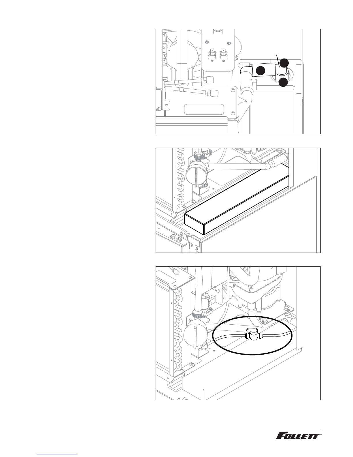
6. Remove two screws securing electrical
box to condenser (Fig.3).
7. Cut wire tie from electrical cable bundle.
8. Install supplied funnel (Fig.4). Fig. 4
Fig. 3
Maestro Plus P425/CP425/EP425 Ice Machine for Symphony FB, CT, and CI Dispensers 23
Page 24
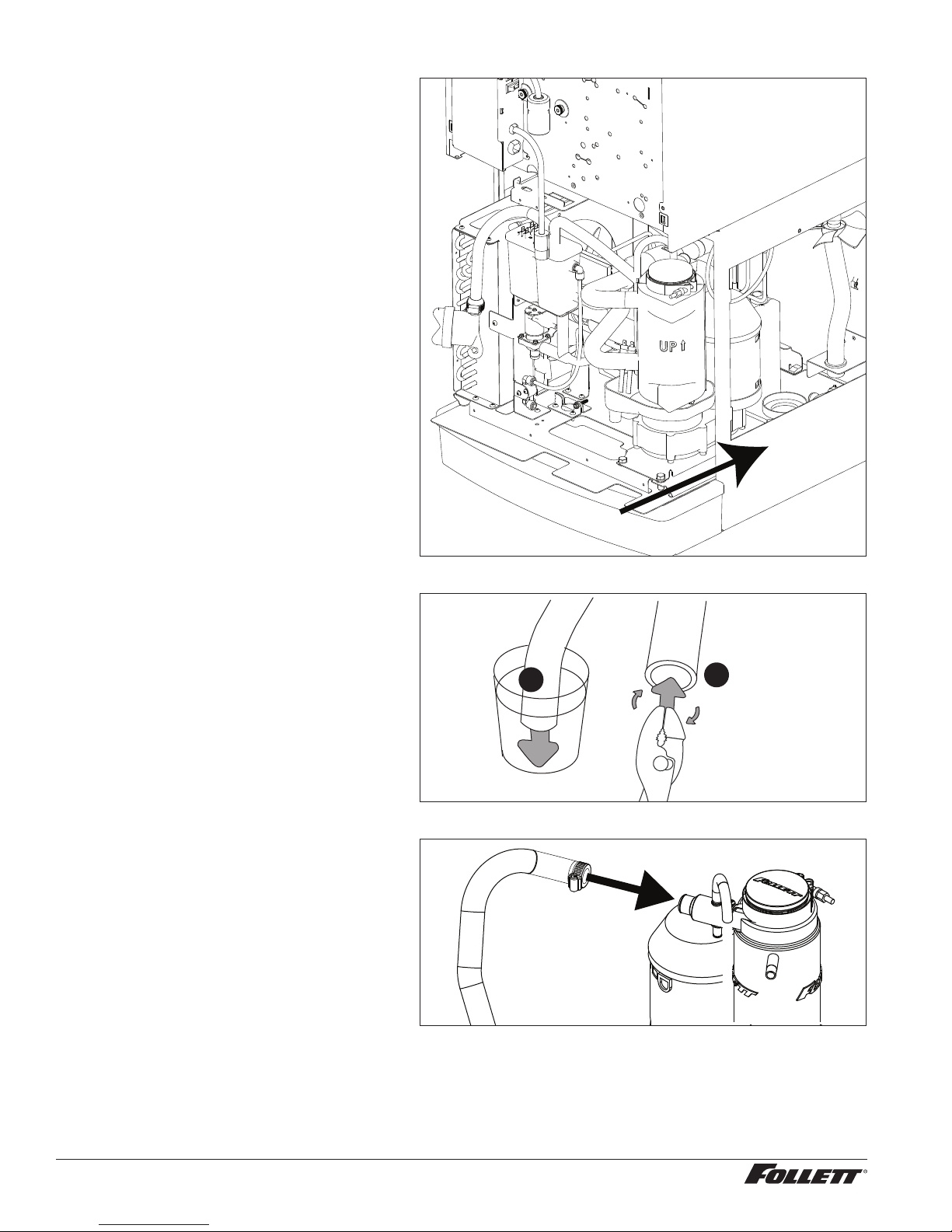
9. Slide supplied module only partially into
2
1
dispenser cabinet (Fig.5).
Fig. 5
10. Heat end of existing ice transport tube
in cup of 160F (71C) hot water to
soften (Fig.6.1) and spread with pliers
(Fig.6.2).
11. Attach ice transport tube to evaporator
compression nozzle (Fig.7).
Fig. 6
Fig. 7
1
2
24 Maestro Plus P425/CP425/EP425 Ice Machine for Symphony FB, CT, and CI Dispensers
Page 25
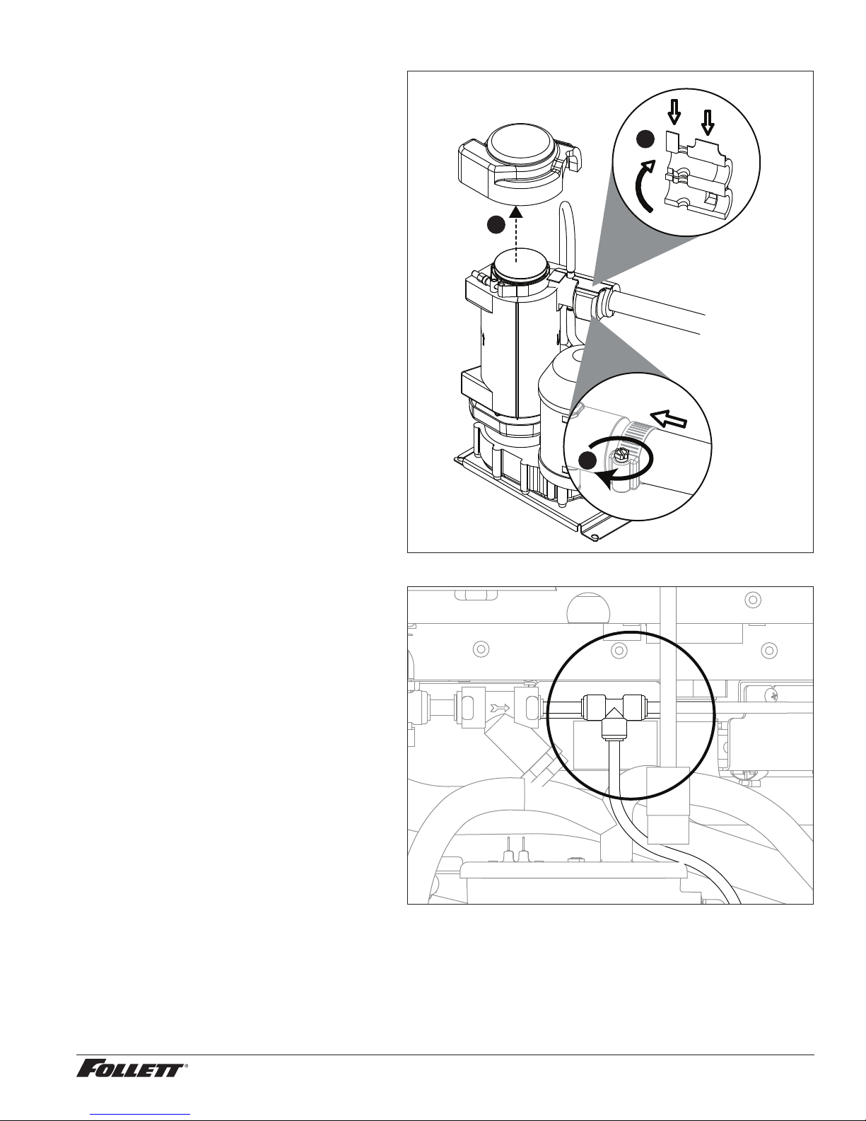
12. Secure with clamp (Fig.8.1).
Note: Clamp must be oriented as shown
in order for the insulation to be placed
properly.
13. Install compression nozzle insulation
(Fig.8.2).
14. Install top bearing insulation (Fig.8.3).
Fig. 8
2
3
1
15. Attach module water tube to existing “T”
tting (Fig. 9).
Fig. 9
Maestro Plus P425/CP425/EP425 Ice Machine for Symphony FB, CT, and CI Dispensers 25
Page 26

16. Hang electrical box on dispenser
front and attach with supplied bracket
(Fig.10).
Fig. 10
01012 186
1 7. Install supplied internal power cord
adapter (Twist-Lock) (Fig.11).
Fig. 11
01069772
26 Maestro Plus P425/CP425/EP425 Ice Machine for Symphony FB, CT, and CI Dispensers
Page 27

18. Plug other end (Mate N Lock) into
electrical box (Fig.12).
Fig. 12
19. Plug two-pin bin thermostat cable into
electrical box (Fig.13).
20. Connect other end to dispenser (Twist
Lock connection) (Fig.14).
2 1. Push module fully into position.
Fig. 13
01069772
Fig. 14
Maestro Plus P425/CP425/EP425 Ice Machine for Symphony FB, CT, and CI Dispensers 27
Page 28

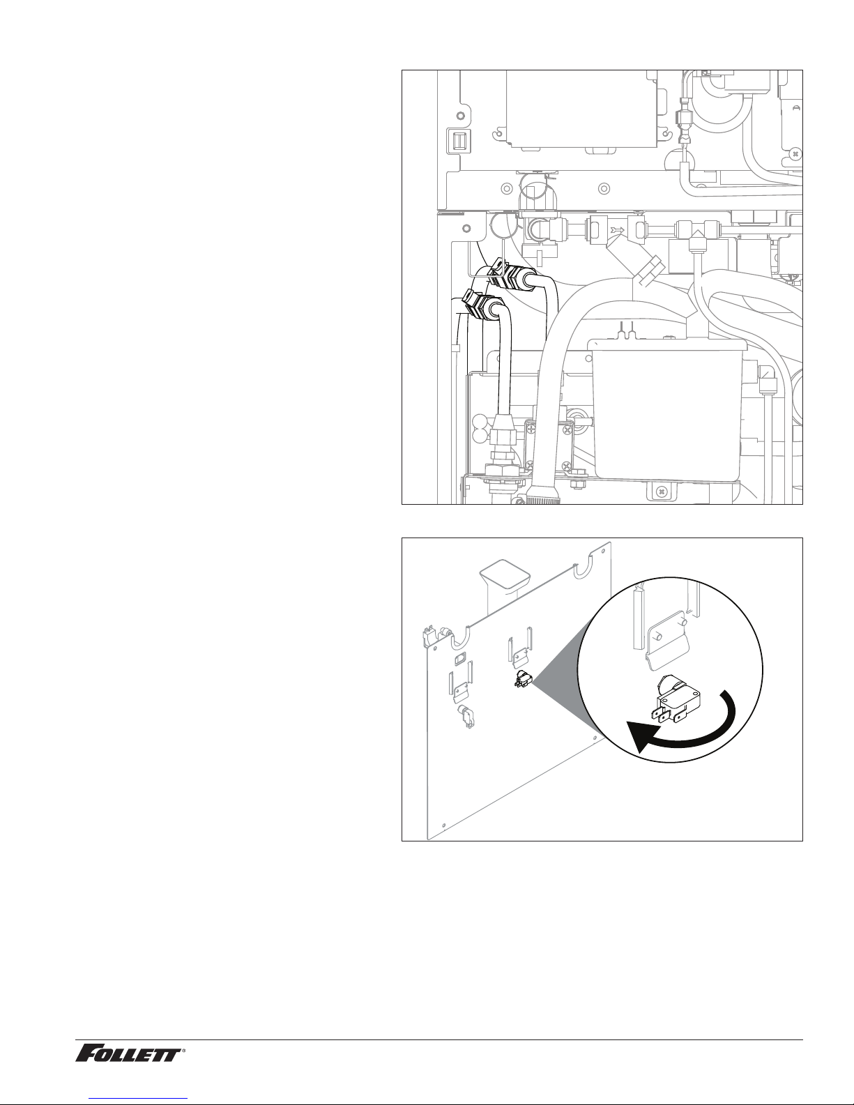
22. Organize power and bin signal cables
and wire tie plugs together (Fig.15).
Fig. 15
23. Install supplied drain tube onto drain
solenoid (Fig.16.1) and evaporator drain
pan (Fig.16.2). Ensure that drain stub
is inserted into hole in ice machine base
above drain cup (Fig.16.3).
Fig. 16
1
2
01062306
3
28 Maestro Plus P425/CP425/EP425 Ice Machine for Symphony FB, CT, and CI Dispensers
Page 29
24. For water-cooled units, make water
connections (Fig. 17)
Fig. 17
25. For lever-operated dispensers, remove
and rotate ice switch on back of splash
panel 180° (Fig. 18).
26. Move splash panel into position, connect
water line to water dispense solenoid,
turn on water to solenoid and attach
splash panel.
2 7. Start up machine and check for proper
operation. Restore power and water to
machine.
28. Sanitize machine prior to use. See
appropriate Operation and Service
manual shipped with the unit.
Fig. 18
Maestro Plus P425/CP425/EP425 Ice Machine for Symphony FB, CT, and CI Dispensers 29
Page 30

30 Maestro Plus P425/CP425/EP425 Ice Machine for Symphony FB, CT, and CI Dispensers
Page 31

Maestro Plus P425/CP425/EP425 Ice Machine for Symphony FB, CT, and CI Dispensers 31
Page 32

Maestro Plus and Symphony are trademarks of Follett LLC.
Follett is a registered trademark of Follett LLC, registered in US.
801 Church Lane • Easton, PA 18040, USA
Toll free (877) 612-5086 • +1 (610) 252-7301
www.follettice.com
01033687R04
© Follet LLC 9/17
 Loading...