

Page 1
Features
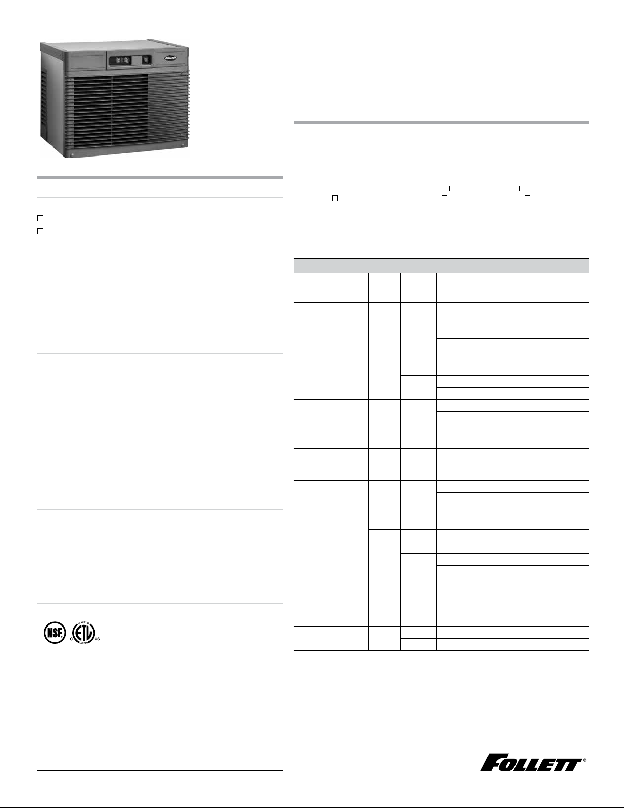
Horizon Elite
1010 series ‑ up to 1061 lb (482 kg) in 24 hours
1410 series ‑ up to 1466 lb (665 kg) in 24 hours
‑ automatically transport ice through a tube with RIDE
technology from up to 75' (22.9 m) away
‑ chewable, compressed nugget ice is preferred
over cubes¹
‑ Chewblet ice dispenses reliably from ice and
beveragedispensers
‑ available with approximately 1.00" (2.54 cm) long
standard Chewblet ice or optional 3/8" (0.95 cm)
long Micro Chewblet
‑ quiet production without noisy harvest cycles
Revolutionary, scale inhibiting design
‑ produces ice that has 15% the TDS of the incoming
water for optimum dispensing and long life in drinks
‑ quarantines and regularly expels scale producing
dissolved solids to dramatically reduce scalebuildup
‑ increases time between descaling and reduces or
eliminates the need for expensive scale treatment
‑ saves 35% water compared to comparable cubers
Durable, attractive ice machine
‑ regular bearing inspection or replacement is
notrequired
‑ upgraded, easy‑to‑read LED operating status and
diagnosticdisplay
Designed with sanitation in mind
®
‑ Agion
silver‑based antimicrobial product protection
of key ice and water contact components²
‑ floatless, sealed design inhibits formation of biofilms
‑ semi‑automatic cleaning and sanitizing system
Warranty
‑ 3 years parts and labor, 5 years compressor parts
Certifications
1
Independent third party studies. Contact Follett for details.
2
Disclaimer: Antimicrobial protection is limited to the treated components and does not treat water or ice.
™
ice
™
Horizon Elite
self-contained 1010, 1410 series Chewblet® ice machine
Short form specification:
Ice machine to be a Follett® Horizon Elite ice machine model
______________ [Insert size/series,condenser type and installation/mounting,
from model number guide] capable of producing compressed nugget ice using
an ecient, sanitary horizontal evaporator/auger system and delivering ice by
a flexible wire reinforced transport tube to ice storage bin, iceand water
dispenser, ice and beverage dispenser, drop‑in dispenser or Ice Manager™
diverter valve system, slide‑out compressor/condenser/evaporator with utility
docking station, front‑mounted unit status display, evaporator water inlet at
harvest end with automatic flush while producing ice, and semi‑automatic
cleaning and sanitizing system, plusall the featureslisted below and mounting/
®
performance‑enhancing accessories checked.
Model configurations
For use with
ice storage bin
Follett Vision
undercounter
ice and beverage
dispenser
Cornelius PR150
undercounter ice and
beverage dispenser ²
countertop
ice and beverage
dispenser
(by others)
drop-in dispenser
(by others)
Ice Manager diverter
valve system
1
Ordered separately.
2
Not compatible with Micro Chewblet ice.
3
Requires top kit (see page 4 for item number).
4
For Micro Chewblet ice, replace second character (C) with an M e.g.HMC1010ABT.
1
Install/
mount Condenser V/Hz/Ph
top
mount
RIDE
™
RIDE
RIDE
top
mount 3
RIDE
RIDE
RIDE
air
water
air
water
air
water
air 208-230/60/1 HCC1010APS HCC1410APS
water 208-230/60/1 HCC1010WPS HCC1410WPS
air
water
air
water
air
water
air 208-230/60/1 HCC1010AMS HCC1410AMS
water 220/60/1 HCC1010WMS HCC1410WMS
208-230/60/1 HCC1010ABT HCC1410ABT
230/50/1 HCE1010ABT HCE1410ABT
208-230/60/1 HCC1010WBT HCC1410WBT
230/50/1 HCE1010WBT HCE1410WBT
208-230/60/1 HCC1010ABS HCC1410ABS
230/50/1 HCE1010ABS HCE1410ABS
208-230/60/1 HCC1010WBS HCC1410WBS
230/50/1 HCE1010WBS HCE1410WBS
208-230/60/1 HCC1010AVS HCC1410AVS
230/50/1 HCE1010AVS HCE1410AVS
208-230/60/1 HCC1010WVS HCC1410WVS
230/50/1 HCE1010WVS HCE1410WVS
208-230/60/1 HCC1010AHT HCC1410AHT
230/50/1 HCE1010AHT HCE1410AHT
208-230/60/1 HCC1010WHT HCC1410WHT
230/50/1 HCE1010WHT HCE1410WHT
208-230/60/1 HCC1010AHS HCC1410AHS
230/50/1 HCE1010AHS HCE1410AHS
208-230/60/1 HCC1010WHS HCC1410WHS
230/50/1 HCE1010WHS HCE1410WHS
208-230/60/1 HCC1010AJS HCC1410AJS
230/50/1 HCE1010AJS HCE1410AJS
208-230/60/1 HCC1010WJS HCC1410WJS
230/50/1 HCE1010WJS HCE1410WJS
Item number
1010 series
4
Item number
1410 series
4
Job
Item
801 Church Lane | Easton, PA 18040, USA
1.800.523.9361 | 1.610.252.7301 | follettice.com
Page 2
Accessories
(31.1 cm)
AIR EXHAUST
29.15
Top kit for ice and beverage dispensers (listed onpage 4)
Water filters (refer to form# 9905)
Wall mount bracket (item# 01085455)
Ice machine stand, height‑adjustable (item# 01085463)
Timer to control one or two ice machines
(item# 00967265)
Longer ice transport tube, specify length: ___ ft/m in
5’/1.5 m increments (10’/3 m provided as standard for
RIDE models) (item#00174896)
SafeCLEAN Plus
1 x 8 oz (237 ml) bottle(item#01147826)
6 x 8 oz (237 ml) bottles(item#01149954)
Carton of 24 x 8 oz (237 ml) bottles
(item#01149962)
SaniSponge
™
ice machine cleaner
™
, 24 sanitary sponges (item# 01075431)
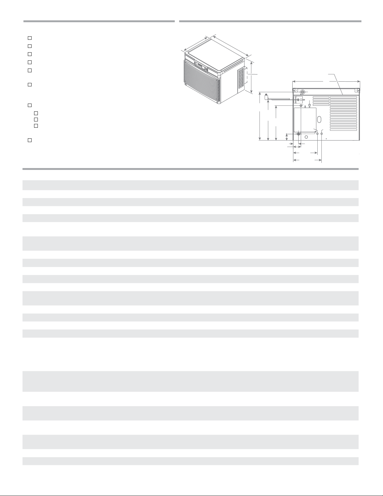
Dimensional drawing
D1
air
intake
W1
(52.9 cm)
for 1410 models only
H1
C1
20.84"
17.49"
(44.4 cm)
15.00"
(38.1 cm)
2.73"
(6.93 cm)
3.34"
(8.48 cm)
C4
(26.5 cm)
Specification
Horizon Elite 1010 series Horizon Elite 1410 series
W1 Width 29.15" (74.0 cm) 29.15" (74.0 cm)
D1 Depth 23.25" (59.1 cm) 25.15" (63.9 cm)
H1 Height 22.50" (57.2 cm) 22.50" (57.2 cm)
Clearance top, left and right–1.00"(2.54 cm) top, left and right–1.00"(2.54 cm)
Electrical (HCC models)
208-230 V/60/1
Electrical (HCE models)
230 V/50/1
Operating power 2.4 kW 3.1 kW
C2 Ice transport tube see page 8 for details see page 8 for details
C3 Water inlet 3/8" OD push-in water inlet – internal connection 3/8" OD push-in water inlet – internal connection
C4 Drain 3/4" MPT, 1" drain required. See page 7 for details. 3/4" MPT, 1" drain required. See page 7 for details.
C5 Ice bin signal cord for Vision applications only for Vision applications only
Water-cooled ice machine
connections
Air temperature 50 -100 F (10 - 38 C) 50 -100 F (10 - 38 C)
Water temperature 45 - 90 F (7 - 32 C) 45 - 90 F (7 - 32 C)
Potable water pressure 10 - 70 psi (69 - 483 kPa) 10 - 70 psi (69 - 483 kPa)
Condenser water pressure 30 - 150 psi (207-1034 kPa) 30 - 150 psi (207-1034 kPa)
Ice production 60 Hz models and 50 Hz water-cooled models see page 8
Energy consumption
90 F (32 C) air,
70 F (21C) water
Heat rejection air-cooled models – 11,300 BTU/hr (2,849 Kcal/hr)
Water consumption 12.0 gal (45 L) of potable water per 100lb (45.4kg) ofice (per
Water flow requirement for
water-cooled models
Refrigerant R404a for 60 Hz models and 50 Hz water-cooled models
Approximate ship weight 275 lb (125 kg) 305 lb (138 kg)
Approximate net weight 265 lb (120 kg) 295 lb (134 kg)
NOTE: For indoor use only
2
Form# 7030
C1 11 amps, requires dedicated 15 amp circuit,
6' (1.8 m) cord, NEMA 6-15 plug
C1 11 amps, requires dedicated 15 amp circuit,
6' (1.8 m) cord only, no plug
C6 – 1/4" FPT condenser inlet
C7 – 1/4" FPT condenser outlet
C1 14 amps, requires dedicated 20 amp circuit,
6'(1.8 m) cord, NEMA 6-20 plug
C1 14 amps, requires dedicated 20 amp circuit,
6'(1.8 m) cord only, no plug
C6 – 1/4" FPT condenser inlet
C7 – 1/4" FPT condenser outlet
60 Hz and 50 Hz models see page 8
50 Hz air-cooled models at 70 F (21 C) air, 50 F (10 C) water –
865 lb (393 kg)
50 Hz air-cooled models at 90 F (32 C) air, 70 F (21 C) water –
734 lb (333 kg)
air-cooled models – 4.80 kWh
water-cooled models – 4.20 kWh
per 100lb(45.4 kg) ice
air-cooled models – 4.84 kWh
water-cooled models – 3.80 kWh
per 100lb(45.4 kg) ice
air-cooled models – 16,000 BTU/hr (4,035 Kcal/hr)
water-cooled models – 12,800 BTU/hr (3,228 Kcal/hr)
AHRI test standards). 12.4 gal (46.9 L) at lowTDS flush setting.
water-cooled models – 16,400 BTU/hr (4,135 Kcal/hr)
12.0 gal (45 L) of potable water per 100lb (45.4kg) of ice (per
AHRI test standards). 12.3 gal (46.5 L) at low TDS flush setting.
1 gallon per minute 1gallon per minute
R404a for 60 Hz and 50 Hz models
R449a for 50 Hz air-cooled models
Self-contained 1010, 1410 series ice machine
C3
(5.84 cm)
10.44"
12.25"
C2
C5
C6C7
2.30"
Page 3
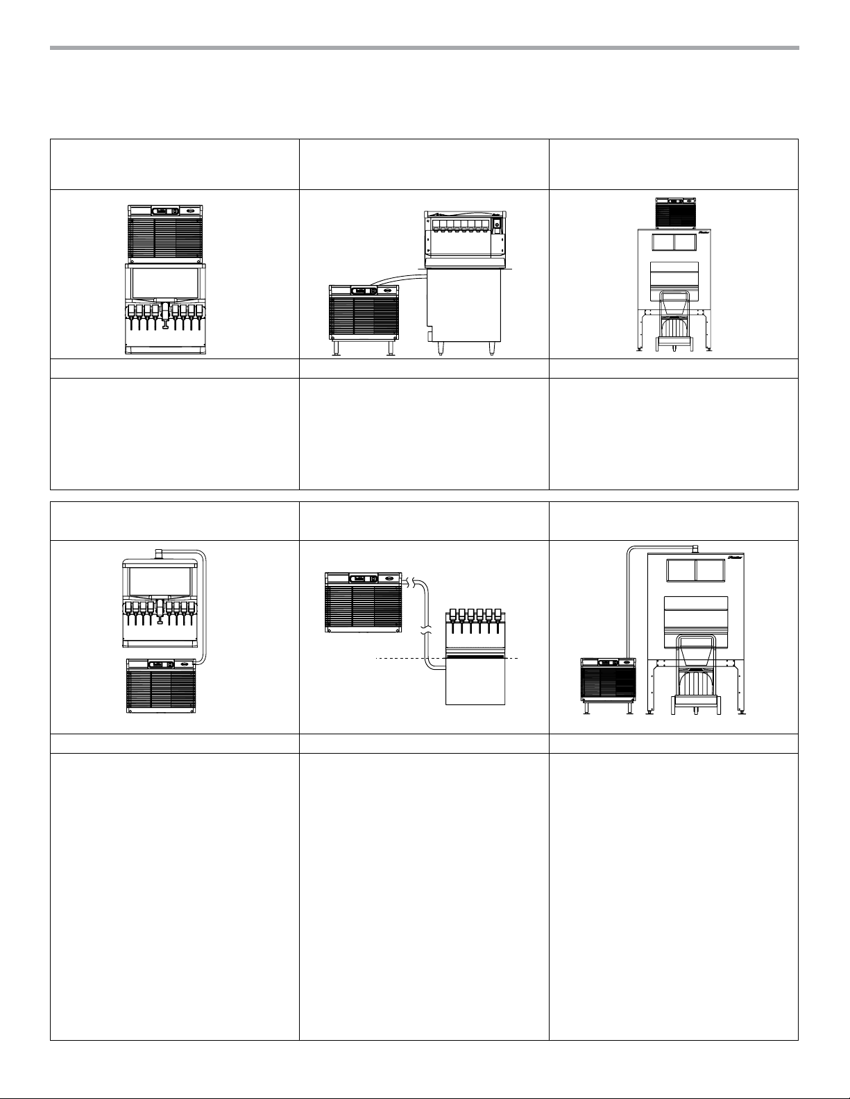
1 – Locating the ice machine
Horizon Elite self‑contained Chewblet ice machines allow top‑mounting or mounting in a base cabinet, on a wall or on a floor stand up
to 75'(22.9 m) from the dispenser or ice bin with RIDE technology. In‑cabinet mounting (RIDE applications) require special attention to
service access, unit ventilation and ice tube runs (seepages 4‑8).
Top mounting – ice and beverage dispensers (by
others)
Important specifier notes Important specifier notes Important specifier notes
1. Dispenser must be compatible with nugget ice.
See page 4 for compatible ice and beverage
dispenser models and top kit numbers.
2. Verify ceiling or soffit height to ensure sufficient
topclearance.
RIDE model – ice and beverage dispensers (by
others)
RIDE model – Follett low-profile
Vision and Cornelius PR150 ice and beverage
dispensers
1. See page 4-6 for critical clearance and
ventingrequirements.
2. Ice transport tube ships with Vision ice and
beverage dispenser (Vision applications only).
3. Ice transport tube ships with Horizon Elite
icemachine for Cornelius dispensers.
RIDE model – drop-in beverage
dispensers (by others)
Top mount on Follett ice storage bins
1. See form# B300 for bin sizing.
2. Verify ceiling or soffit height to ensure
topclearance.
3. Locate floor sink or grate and drains in front of
storage bin.
4. Do not position bin drain lines to block
Ice•DevIce
RIDE model – Follett ice storage bins
™
bin cart.
Important specifier notes Important specifier notes Important specifier notes
1. Dispenser must be compatible with nugget
ice. Compatible dispensers include Coca-Cola
Freestyle 9000, Cornelius DB/ID/DF150/175,
Lancer 4500-22N, FS-16N, FS-22N and FS-44N,
Servend MD150/175/200/250, SV175/200/250,
MDH-402 and FollettSymphony Plus™ 110CM, as
well as dispensers listed on page 4.
1. Compatible with the following dispensers:
Cornelius 1522, 1722, 2323, and Lancer 2200,
2300, 23300.
2. Require 12.00" (30.5 cm) of access space for
installation on transport tubeside.
3. See page 4-6 for critical clearancerequirements.
1. See form# B300 for bin sizing.
2. Locate floor sink or grate and drains in front of
storage bin.
3. Do not position bin drain lines to block Ice•DevIce
bin cart.
2. Top kit MSF30SC required with Coca-Cola Freestyle
7000. Top adapter 46412 and ice kit 46430 must
also be ordered from Coca-Cola. Top kit HSF26SC
required with Coca-Cola Freestyle 9100. Consult
with Coca-Cola and Follett to qualify application
prior to ordering.
3. RIDE application is approved only for PepsiSpire
3.0, 5.0 and 4.1 designed for top mount ice
machines and requires MSP24SC for 3.0 and
MSP30SC for 5.0 and 4.1, ordered separately. For
manual fill versions of Pepsi Spire 3.0, 5.0 and
4.1, contact factory.
4. See page 4-6 for critical clearance and
ventingrequirements.
Self-contained 1010, 1410 series ice machine
Form# 7030
3
Page 4

1 – Locating the ice machine (continued)
Top mounting – compatible ice and beverage dispensers
Manufacturer Model number
Coca‑Cola
dispensers
Freestyle 7000 30.10 (76.5) 33.11 (84.1) 47.00 (119.38) H30F30‑F
1
Width
in (cm)
Depth
in (cm)
2
3
Height
in (cm) Top kit
4, 5
DB/ED/DF 200 series 30.00 (76.2) 30.00 (76.2) 34.38 (87.3) H30C30‑F
DB/ED/DF 250 series 30.00 (76.2) 30.00 (76.2) 38.38 (97.5) H30C30‑F
Cornelius
dispensers
DB/ED/DF 300 series 44.00 (111.8) 30.00 (76.2) 34.00 (86.4) H30C44‑(F or B)
FlavorFusion / Overload 30.00 (76.2) 30.70 (78.0) 39.38 (100.0) H30C30‑F‑FF
6
IDC215 30.00 (76.2) 30.70 (78.0) 39.38 (100.0) H30C30‑F‑IDC
IDC255 and Pro Fast Gate 30.00 (76.2) 30.70 (78.0) 36.38 (92.4) H30C30‑F‑IDC
7
4500‑30N 30.00 (76.2) 30.50 (77.5) 36.50 (92.7) H30L30‑F
FS‑30N 30.00 (76.2) 30.50 (77.5) 42.13 (107.0) H30L30‑F
Lancer
dispensers
Bevariety 30.00 (76.2) 31.00 (78.7) 37.75 (95.9) H22L30‑F‑STP
Sensation 30" 30.00 (76.2) 31.00 (78.7) 38.25 (97.2) H30L30‑F‑STP
Sensation 44" 44.00 (111.8) 31.00 (78.7) 39.38 (100.0) H22L44‑F‑STP
Touchpoint 32.50 (82.6) 33.70 (85.6) 40.00 (101.6) H30L30‑F‑STP
Pepsi
dispensers
Servend
dispensers
1
All approved dispensers can be filled with a RIDE model Horizon Elite ice machine without a top kit except for Coca-Cola Freestyle 7000 and Pepsi Spire 3.0, 5.0 and 4.1, see page 3 for details.
2
Requires minimum 1.00" (2.54 cm) clearance between back of dispenser and wall.
3
Net height after installation of top kit (excluding height of ice machine).
4
Consult with Coca-Cola and Follett to qualify application prior to ordering.
5
Top adapter 46412 and ice kit 46430 must also be ordered from Coca-Cola.
6
Specify “F” for front facing, or ”B“ for backward facing units.
7
Contact factory regarding IDC Pro.
Spire 5.0 / 4.1 30.50 (77.5) 36.00 (91.4) 42.75 (108.6) H30P30‑F
MDH‑302 42.80 (108.7) 31.00 (78.7) 32.38 (82.2) H30S44‑(F or B)
6
2 – Undercounter/in-cabinet mounting
Cabinet details
Important specifier notes
1. Cabinet door opening must meet
minimum size requirements shown
and be free of obstructions to allow
ice machine to slide out (no lip or
utilities to block removal).
2. Cabinet base must be capable
of supporting ice machine and
allow ice machine to rest flat on
cabinetbottom.
3. No counter supports, electric or
plumbing can run in front of the
icemachine.
Cabinet door opening
1010/1410 series models require 1.00" (2.54 cm) all around,
31.00"W x 23.5"H (78.7 cm x 59.69 cm) minimum
slides
out
Cabinet base
must be flat and free of obstructions
(no lip or utilities to block removal)
4
Form# 7030
Self-contained 1010, 1410 series ice machine
Page 5

3 – Undercounter/in-cabinet mounting and ventilation
Using Follett supplied grilles
Horizon Elite ice machines can be installed undercounter/in‑cabinet to fill bins or dispensers using RIDE technology. Care must be
taken to ensure proper cabinet venting to avoid recirculation of hot air. Improper venting can cause ice machine outages.
Supplied
grilles
Horizon Elite
ice machine
exhaust
cabinet door
18.00" (45.7 cm)
minimum
23.50"
(59.69 cm)
minimum
air intake gasket
air in
door & gasket
must mate
directly
25.25" (64.1) cm)
minimum
Cabinet door
must mate directly
to air intake gasket
r
electric
water
drain
12.00" (30.5 cm) minimum
between ice machine
and dispenser
Horizon Elite ice machine
Ice transport tube
minimum 1/4" per foot
(2 cm per meter)
pitch toward ice machine
secure to prevent dips
and traps from forming
see dispenser
specification
sheet for
installation
requirements
Completed installation with
gasket and door in place –
Side view
25.25" (64.1 cm) min.
locating
cutout
2.00"
(5.08 cm)
supplied intake grille
cutout for supplied air intake grille
24.00"W x 16.00"H (61.0 cm x 40.6 cm)
Important specifier notes for using Follett supplied grilles
1. The supplied exhaust grille must be located at least 18.00"(45.7cm) from the
supplied air intake grille (exhaust air must notrecirculate with intake air).
2. Cabinet interior must be open to allow for unrestricted exhaust airflow.
3. Ice transport tube needs minimum 1/4" per foot (2 cm per meter) pitch toward
ice machine and should be secured to prevent dips and traps from forming.
Self-contained 1010, 1410 series ice machine
23.50"
(59.7 cm)
minimum
2.25" (5.72 cm)
cutout
bottom of ice machine
side of ice machine
Front
4. Cabinet door must mate directly to air intake gasket.
5. Cabinet interior must provide a minimum clear space of 23.50" (59.7 cm) high
by 25.25" (64.1 cm) deep.
6. Cutout for supplied grilles must meet minimum size requirements
shownabove.
7. Utilities should be conveniently located as shown.
Form# 7030
5
Page 6

3 – Undercounter/in-cabinet mounting and ventilation (continued)
Using grilles by others/alternate cabinet ventilation
Cabinets with ventilation or louvers other than those provided require special consideration to provide proper ventilation.
Recirculation of hot air will reduce ice machine performance and can cause ice machine outages.
Grilles by others/
alternate cabinet
ventilation
18.00" (45.7 cm)
minimum
exhaust
18.00" (45.7 cm)
minimum
All counter ventilation
within 18.00" (45.7 cm) of
air inlet must be blocked to
prevent exhaust-air recirculation
air intake gasket
cabinet door
air in
Cabinet door
must mate directly
to air intake gasket
Horizon Elite ice machine
exhaust
Minimum open air space
door & gasket
must mate
directly
side
view
Grilles by others/
alternate cabinet ventilation
Important specifier notes for using grilles supplied by others/alternate cabinet ventilation
1. Exhaust must be at least 18.00"(45.7cm) from air intake (exhaust air must
notrecirculate with intake air).
2. Cabinet interior must be open to allow for unrestricted exhaust airflow.
3. Ice transport tube needs minimum 1/4" per foot (2 cm per meter) pitch toward
ice machine and should be secured to prevent dips and traps from forming.
4. Ducting must be provided if cabinet door does not mate directly to air
intakegasket.
5. Cabinet interior must provide a minimum clear space of 23.50" (59.7 cm) high
by 25.25" (64.1 cm) deep.
6. Grilles by others must meet minimum requirements for open air space
shownabove.
7. Utilities should be conveniently located as shown.
x
xx
x
yn
= sq. in. of open air space
= (# of openings)
n
minimum 250 sq. in.
open air space
y
6
Form# 7030
Self-contained 1010, 1410 series ice machine
Page 7

4 – Horizon Elite ice machine mounting accessories
Optional wall mount bracket Optional machine stand Important specifier notes
1. For secure wall mounting, specify optional
wall mount bracket.
2. Wall and fasteners must support the weight
of the ice machine, bracket, supply water and
ice. Use of a backing board may be required
with hollow wall construction.
3. Machine stand mounting adds 6.88" (17.48cm)
to height of ice machine.
4. No dips in tube routing allowed.
5. Ice transport tube needs minimum 1/4"
per foot (2 cm per meter) pitch toward ice
machine and should be secured to prevent
6.88"
(17.50 cm)
dips and traps from forming.
30.50"
(77.7 cm)
22.00"
(55.9 cm)
25.50"
(64.8 cm)
A
B
A - 25.2" (64.0 cm)
B - 28.7" (72.9 cm)
5 – Horizon Elite drain - specifier guidelines
Flush drain plumbing – For regular machine drainage
➊
Minimum 8"
radius
2 ft x 1" OD
silicone tubing
3/4" barb x 3/4" FPT
➋
3/4" MPT x 1" slip
1" Stand pipe/drain
➌
13.00"
(33.0 cm)
21.00"
(53.3 cm)
Important specifier notes: Where code allows, follow
recommendation below.
1. Connect the silicone tubing to the ice machine 3/4"
drainbarb
➊.
2. Assemble the 3/4" barb x 3/4" FPT to the 3/4" MPT x
1" slip. Connect the other end of the silicone tubing to
the 3/4" barb
➋.
3. Connect the 1" slip fitting to the 1" stand pipe/drain
Note: Minimum 8" radius on silicone drain line. Drain line
from the ice machine must have at least 1/4" per foot
pitch (6.4 mm/0.3 m).
Note: Stand pipe/drain provided by others. All other
components provided with ice machine.
➌.
Chassis drain plumbing – To assist with condensate in high humidity areas
Self-contained 1010, 1410 series ice machine
Important specifier notes: Where code allows, follow
recommendation below.
1. Plug must be removed from John Guest fitting.
2. Route 3/8" drain tubing through knockout in back of
docking station and insert fully into John Guest fitting
connection at the rear of the machine chassis. Route
other end of 3/8" drain tubing to drain.
3. Drain must slope 1/4" inch per foot ( 6 mm per 30.4 cm).
Form# 7030
7
Page 8

6 – Horizon Elite ice tube runs - specifier guidelines
Long tube runs for RIDE remote ice delivery equipment
beverage
dispenser
support
straps
minimum of
6.00" (15.24 cm)
turn/corner
radius
ice transport tube –
1 3/16" OD,
2 1/8" OD with insulation
maximum
2' (60.9 cm)
transport tube slope
(toward ice machine)
1/4"
1'
(2 cm per meter)
wall-mounted
ice machine
Important specifier notes
1. 75' (22.9 m) maximum ice transport tuberun.
2. Tubing routing bends must have a
6.00"(15.24 cm) radius or larger.
3. Dips and traps are not allowed. If not
supported from underneath, secure insulated
ice transport tube at least every2' (60.9 cm)
to prevent drips andtraps.
4. Relative humidity levels above 80% in areas
where the ice machine or ice transport tube is
located may produce excessive condensation
that will cause water damage.
5.
Contact factory for recommendations
on
running tubing through a decorative soffit
orchase.
Ice production – Horizon Elite 1010 series, 60 Hz,
air-cooled models
Inlet water
temperature
F (C)
50 (10)
60 (16)
70 (21)
80 (27)
90 (32)
60 (16) 70 (21) 80 (27) 90 (32)
1160 (526) 1061 (481) 962 (436) 825 (374) 688 (312)
1093 (496) 1001 (454) 909 (412) 795 (361) 681 (309)
1026 (465) 941 (427) 857 (389) 765 (347) 674 (306)
971 (440) 893 (405) 815 (370) 730 (331) 644 (292)
917 (416) 941 (427) 773 (350) 694 (315) 614 (279)
Ambient air temperature F (C)
100 (38)
Ice production – All Horizon Elite 1010 series,
water-cooled models
Potable
water
temperature
F (C)
50 (10)
60 (16)
70 (21)
80 (27)
90 (32)
60 (16) 70 (21) 80 (27) 90 (32) 100 (38)
1096 (498) 1043 (473) 1001 (454) 947 (430) 892 (405)
1006 (457) 970 (440) 938 (426) 888 (403) 839 (381)
917 (416) 898 (408) 874 (396) 830 (377) 786 (357)
874 (397) 826 (375) 826 (375) 787 (357) 749 (340)
831 (377) 778 (353) 778 (353) 745 (338) 712 (323)
Condenser water temperature F (C)
Ice production – All Horizon Elite 1410 series,
air-cooled models
Inlet water
temperature
F (C)
50 (10)
60 (16)
70 (21)
80 (27)
lb (kg) production in 24 hr
90 (32)
Ice production – All Horizon Elite 1410 series,
water-cooled models
Potable
water
temperature
F (C)
50 (10)
60 (16)
70 (21)
80 (27)
lb (kg) production in 24 hr
90 (32)
Ambient air temperature F (C)
60 (16) 70 (21) 80 (27) 90 (32) 100 (38)
1593 (723) 1466 (665) 1339 (607) 1230 (558) 1121 (508)
1518 (689) 1396 (633) 1275 (579) 1163 (528) 1052 (478)
1442 (654) 1327 (602) 1211 (549) 1097 (498) 982 (446)
1394 (632) 1272 (577) 1150 (522) 1050 (477) 950 (431)
1345 (610) 1327 (602) 1089 (494) 1004 (456) 918 (417)
Condenser water temperature F (C)
60 (16) 70 (21) 80 (27) 90 (32) 100 (38)
1436 (652) 1411 (641) 1385 (607) 1370 (622) 1354 (615)
1417 (643) 1367 (633) 1318 (621) 1307 (593) 1296 (588)
1397 (634) 1324 (602) 1251 (568) 1245 (565) 1238 (562)
1318 (598) 1253 (577) 1189 (540) 1170 (531) 1151 (522)
1238 (562) 1183 (602) 1127 (512) 1096 (497) 1064 (483)
lb (kg) production in 24 hr
lb (kg) production in 24 hr
Agion is a registered trademark of Sciessent LLC.
HORIZON ELITE, ICE•DEVICE, ICE MANAGER, MICRO CHEWBLET, SAFECLEAN PLUS, SANISPONGE, SYMPHONY PLUS and VISION are trademarks of FollettLLC.
CHEWBLET, FOLLETT and RIDE are registered trademarks of Follett LLC, registered in the US.
Follett reserves the right to change specifications at any time without obligation. Certifications may vary depending on country of origin.
Self-contained 1010, 1410 series ice machine
7030‑202004 | © Follett LLC
801 Church Lane | Easton, PA 18040, USA
1.800.523.9361 | 1.610.252.7301 | follettice.com
 Loading...